Embed Size (px)
Citation preview

DATASHEET 2017-05-13
STM0X0000 1
SYNCHROTEQ® MV UNITS
DATASHEET
(Panel mount configuration shown here)
STM0x0000
2017-05-13
©2017 VIZIMAX Inc. All rights reserved

TABLE OF CONTENT DATASHEET 2017-05-13
STM0X0000 2
TABLE OF CONTENT
TABLE OF CONTENT .................................................................................................................................. 2
PRODUCT OVERVIEW ............................................................................................................................... 3
APPLICATIONS OF SYNCHROTEQ MV..........................................................................................................................................5
SYNCHROTEQ MV HIGHLIGHT ..................................................................................................................................................6
SYNCHROTEQ MV UNITS - MAJOR FEATURES ..............................................................................................................................7
CONTROLLED SWITCHING .........................................................................................................................................................8
CIRCUIT-BREAKER ELECTRICAL WEAR MONITORING FUNCTION ........................................................................................................9
OPERATING ENVIRONMENT ....................................................................................................................................................10
COMMUNICATION LINKS – TIME SYNCHRONIZATION - SOFTWARE..................................................................................................12
SYNCHROTEQ CONFIGURATION SUITE AND WEB INTERFACE .........................................................................................................16
SYNCHROTEQ MV CONNECTORS AND HMI IDENTIFICATION .........................................................................................................18
TECHNICAL SPECIFICATIONS ................................................................................................................... 19
POWER SUPPLY ....................................................................................................................................................................21
CONTROL AND COMMUNICATION ............................................................................................................................................22
AC MEASUREMENT INPUTS ....................................................................................................................................................24
DC MEASUREMENT INPUTS ....................................................................................................................................................28
DIGITAL INPUTS / OUTPUTS ....................................................................................................................................................29
FUNCTIONAL ANALYSIS TOOLS ................................................................................................................................................32
MOUNTING CONFIGURATIONS ............................................................................................................... 33
PHYSICAL DIMENSIONS ..........................................................................................................................................................33
STANDARD MOUNT (STANDALONE) .........................................................................................................................................33
PANEL MOUNT ....................................................................................................................................................................35
RACK MOUNT .....................................................................................................................................................................37
ORDERING INFORMATION ...................................................................................................................... 38

DATASHEET 2017-05-13 PRODUCT OVERVIEW
3 STM0X0000
PRODUCT OVERVIEW
SynchroTeq MV is an extension of the SynchroTeq System Components aimed at MV switchgears and circuit breakers up to 69kV.
A compact Control Switching Device (CSD) for 1, 2 or 3 phase medium voltage switchgears, the SynchroTeq MV is specifically designed for load switching projects up to 69kV. It is proposed in two versions: SynchroTeq MVR and SynchroTeq MVX respectively.
The SynchroTeq MV features a comprehensive set of Controlled Switching modes, and performs significantly well in a variety of MV applications as shown in Table 1 below:
TABLE 1 SYNCHROTEQ UNIT VS LOAD SWITCHING APPLICATION
Load Switching Application SynchroTeq MV SynchroTeq Plus
SynchroTeq MVR
SynchroTeq MVX
SynchroTeq Plus
SynchroTeq Plus + VL measurement
Discharged Capacitor Banks - MSC / MSCDN Shunt Reactors – MSR Power Transformers (Peak Voltage) Power Transformers (Residual Flux) Power Transformers in Parallel (Residual Flux)* Compensated / Uncompensated Transmission lines (any kV level)
Cables (MV, HV, submarine)
Partially Charged Capacitor Banks – MSC/FLT
CB and a half (any kV level)
Voltage range Up to 69kV Up to EHV and UHV
PRODUCT OVERVIEW DATASHEET 2017-05-13
STM0X0000 4
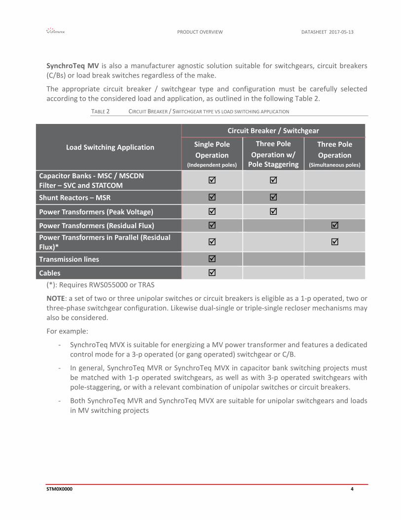
SynchroTeq MV is also a manufacturer agnostic solution suitable for switchgears, circuit breakers (C/Bs) or load break switches regardless of the make.
The appropriate circuit breaker / switchgear type and configuration must be carefully selected according to the considered load and application, as outlined in the following Table 2.
TABLE 2 CIRCUIT BREAKER / SWITCHGEAR TYPE VS LOAD SWITCHING APPLICATION
Load Switching Application
Circuit Breaker / Switchgear
Single Pole Operation
(Independent poles)
Three Pole Operation w/
Pole Staggering
Three Pole Operation
(Simultaneous poles) Capacitor Banks - MSC / MSCDN Filter – SVC and STATCOM
Shunt Reactors – MSR Power Transformers (Peak Voltage) Power Transformers (Residual Flux) Power Transformers in Parallel (Residual Flux)*
Transmission lines Cables
(*): Requires RWS055000 or TRAS
NOTE: a set of two or three unipolar switches or circuit breakers is eligible as a 1-p operated, two or three-phase switchgear configuration. Likewise dual-single or triple-single recloser mechanisms may also be considered.
For example:
- SynchroTeq MVX is suitable for energizing a MV power transformer and features a dedicated control mode for a 3-p operated (or gang operated) switchgear or C/B.
- In general, SynchroTeq MVR or SynchroTeq MVX in capacitor bank switching projects must be matched with 1-p operated switchgears, as well as with 3-p operated switchgears with pole-staggering, or with a relevant combination of unipolar switches or circuit breakers.
- Both SynchroTeq MVR and SynchroTeq MVX are suitable for unipolar switchgears and loads in MV switching projects

DATASHEET 2017-05-13 PRODUCT OVERVIEW
5 STM0X0000
APPLICATIONS OF SYNCHROTEQ MV The outstanding performance of SynchroTeq MV devices apply to a variety of MV switchgears – regardless of the make – and can be leveraged for optimized switching of shunt reactors, discharged and partially charged capacitors bank, harmonic filters, power transformers and cables.
Among other applications, SynchroTeq MV is a powerful, communication-enabled IED suitable for:
Renewable Power Generation: o Solar farms: energizing inverters’ transformers for inrush current/voltage drop
mitigation, improved power delivery, connection to the grid, grid code compliancy. o Wind: energizing power transformers in WTGs, advanced switching of feeders, for
inrush current/voltage drop mitigation, improved power delivery, connection to the grid, grid code compliancy, energizing step-up transformers in STATCOMs.
o Switching reactive loads, in standalone or in SVC/hybrid-STATCOM systems. o Energizing power cables.
Conventional Power Generation: o Energizing power transformers in grid-scale waste-to-energy or CHP or genset or
gas turbine projects. o Energizing power transformers in off-grid power generation: gensets, gas turbines
and more. o Switching reactive loads. o Energizing power cables.
Industry: o Electrical Arc Furnaces: transformer switching, MSC/MSR/FLT in SVC or STATCOM
systems, reduction of switchgear wear, preservation and lifespan improvement of MV switchgears and transformers.
o Transportation & Railways: energizing power transformers for rectifiers and inverters in DC traction substations, MV capacitor banks for VAR Compensation.
o Oil&Gas: energizing power transformers with limited impacts of voltage disturbances/inrush currents on gensets, MV drives, power distribution. Capacitor bank switching, MV cables.
MV Equipment / FACTS: o Fast-switching of capacitor banks (MSC), shunt reactor switching (MSR), harmonic
filters (FLT) combined with power electronics (ie: hybrid STATCOMs). o Energizing step-up transformers in Energy Storage systems. o Capacitors bank switches for PF Correction/VAR Compensation. o Advanced MV switchgears for power transformer energization.
Power Grids: o MV power transformers in substations. o Enhanced penetration of Renewable Energy. o Grid connection of DERs: waste-to-energy, CHP…etc o Capacitor bank switching.

PRODUCT OVERVIEW DATASHEET 2017-05-13
STM0X0000 6
SYNCHROTEQ MV HIGHLIGHT
For All MV Switchgears up to 69kV 3-p operated, w/ and w/o pole staggering 1-p operated
Various Apps and Loads Discharged reactive loads Single or Three phase Transformers Advanced Switching of partially charged
capacitor banks and filters w/ residual charge measurement.
Strong Engine, Web-based operation Stores up to 500 events and waveforms Secured Web-Based interface
Best-in-class MV transformer energization MVX version w/ residual flux calculation For 1-p and 3-p operated Switchgears
Additional Modules and Tools: OPC UA server, data transfer for SCADA
and DCS in substation or in central sites.

PRODUCT OVERVIEW DATASHEET 2017-05-13
STM0X0000 7
SYNCHROTEQ MV UNITS - MAJOR FEATURES
Features SynchroTeq MVR SynchroTeq MVX Circuit breaker coils control outputs
6x Coil control outputs (3x Open + 3x Close coils)
AC current inputs 3x AC current measurement inputs (1 or 5 A)
AC voltage inputs 1x AC voltage input for source voltage measurement
Additional AC voltage inputs
N/A 3x AC voltage inputs for the measurement of the power transformer voltage or bus bar voltage for partially charged capacitors
Digital Inputs
10x digital inputs: • Three inputs for C/B contact position (52a contacts) • Two inputs for C/B or switchgear control (OPEN/CLOSE commands) • One input to set SynchroTeq MV Out of Service • Four programmable inputs for C/B monitoring and commands (with separate
returns)
Compensation inputs 2x C/B timing compensation inputs: • Temperature input (RTD or 4-20 mA from external sensor) • C/B coil voltage input
Signalization Outputs 4x dry contact relay outputs: Alarms
Power Supply 24Vdc or 48Vdc or 110Vdc or 125Vdc or 220Vdc
Local user Interface • Two push buttons (rear and front panel) • Five LEDs (front panel) – Seven LEDs (rear panel)
Communications ports
• 1x USB port • 2x 100Base-TX Ethernet • 1x RS-232 Serial port • 1x RS-485 Isolated Serial port
Time synchronization
• NTP time server on Ethernet • IEEE PTP 1588 clock source on Ethernet • IRIG-B clock source using the optional IRIG-B RWC0Y0001 module:
• IRIG-B000/B004 IEEE C37.118 • IRIG-B000/B004 IEEE-1344 • IRIG-B003
• Manual synchronization from PC computer
Functional tools • Event capture (up to 500 events including COMTRADE compatible waveform files) • SynchroTeq Event Analyzer • Secured web interface
PRODUCT OVERVIEW DATASHEET 2017-05-13
STM0X0000 8
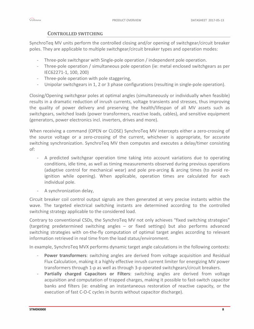
CONTROLLED SWITCHING SynchroTeq MV units perform the controlled closing and/or opening of switchgear/circuit breaker poles. They are applicable to multiple switchgear/circuit breaker types and operation modes:
- Three-pole switchgear with Single-pole operation / independent pole operation. - Three-pole operation / simultaneous pole operation (ie: metal enclosed switchgears as per
IEC62271-1, 100, 200) - Three-pole operation with pole staggering, - Unipolar switchgears in 1, 2 or 3 phase configurations (resulting in single-pole operation).
Closing/Opening switchgear poles at optimal angles (simultaneously or individually when feasible) results in a dramatic reduction of inrush currents, voltage transients and stresses, thus improving the quality of power delivery and preserving the health/lifespan of all MV assets such as switchgears, switched loads (power transformers, reactive loads, cables), and sensitive equipment (generators, power electronics incl. inverters, drives and more).
When receiving a command (OPEN or CLOSE) SynchroTeq MV intercepts either a zero-crossing of the source voltage or a zero-crossing of the current, whichever is appropriate, for accurate switching synchronization. SynchroTeq MV then computes and executes a delay/timer consisting of:
- A predicted switchgear operation time taking into account variations due to operating conditions, idle time, as well as timing measurements observed during previous operations (adaptive control for mechanical wear) and pole pre-arcing & arcing times (to avoid re-ignition while opening). When applicable, operation times are calculated for each individual pole.
- A synchronization delay,
Circuit breaker coil control output signals are then generated at very precise instants within the wave. The targeted electrical switching instants are determined according to the controlled switching strategy applicable to the considered load.
Contrary to conventional CSDs, the SynchroTeq MV not only achieves “fixed switching strategies” (targeting predetermined switching angles – or fixed settings) but also performs advanced switching strategies with on-the-fly computation of optimal target angles according to relevant information retrieved in real time from the load status/environment.
In example, SynchroTeq MVX performs dynamic target angle calculations in the following contexts:
- Power transformers: switching angles are derived from voltage acquisition and Residual Flux Calculation, making it a highly effective inrush current limiter for energizing MV power transformers through 1-p as well as through 3-p operated switchgears/circuit breakers.
- Partially charged Capacitors or Filters: switching angles are derived from voltage acquisition and computation of trapped charges, making it possible to fast-switch capacitor banks and filters (ie: enabling an instantaneous restoration of reactive capacity, or the execution of fast C-O-C cycles in bursts without capacitor discharge).
DATASHEET 2017-05-13 PRODUCT OVERVIEW
9 STM0X0000
CIRCUIT-BREAKER ELECTRICAL WEAR MONITORING FUNCTION SynchroTeq MV measures the electrical wear of the circuit breaker at each operation (i²t), including protection and local switching operations. The i2t value for each phase is reported in the switching operation event. The accumulated electrical wear for each phase is also computed and stored in the unit and displayed by the web interface.
SynchroTeq MV is not only a CSD, but also a circuit breaker monitoring tool that drastically reduces the C/B maintenance costs by allowing for scheduling maintenance only when required due to excessive wear.

PRODUCT OVERVIEW DATASHEET 2017-05-13
STM0X0000 10
OPERATING ENVIRONMENT SynchroTeq MV can be installed in the low voltage/control compartments of switchgears, as well as in control & relay rooms, or in independent enclosures. It is therefore offered in three housing versions for easy integration in various applications (see MOUNTING CONFIGURATIONS for details). SynchroTeq MV is typically connected to the following subsystems:
DC power supply: uninterruptible power source for the substation / switchgear control and protection equipment.
Controlled MV switchgear or circuit breaker: control outputs, statuses/pole positions. Protection relays. AC measurements: system/source voltage, load current, as well as load voltage when
applicable. Condition measurements: temperature or pressure transducer when applicable. Local control panels, networked SCADA/DCS systems, network infrastructure:
switchgear or C/B control in substations or in equipment.
SWITCHING A DISCHARGED CAPACITOR BANK OR SHUNT REACTOR
SynchroTeq MVR is intended for the controlled switching of shunt reactors, discharged capacitor banks, harmonic filters, power cables, power transformers, all based on fixed switching angle strategies.
FIGURE 1 EXAMPLE OF SYNCHROTEQ MVR IN DISCHARGED CAPACITOR BANK OR SHUNT REACTOR APPLICATION

DATASHEET 2017-05-13 PRODUCT OVERVIEW
11 STM0X0000
ENERGIZING POWER TRANSFORMERS WITH RESIDUAL FLUX MANAGEMENT
SynchroTeq MVX features AC voltage measurement channels for the acquisition of power transformer voltage (from primary or secondary winding) and residual flux calculation for each phase. When re-energizing, the optimal closing angle is derived from the residual flux in transformer’s core for the mitigation or elimination of the inrush currents (Figure 2).
FIGURE 2 EXAMPLE OF SYNCHROTEQ MVX FOR ENERGIZING A POWER TRANSFORMER
SWITCHING A PARTIALLY CHARGED CAPACITOR BANK OR FILTER
SynchroTeq MVX features AC voltage measurement channels suitable for the acquisition of residual charges trapped in capacitive loads such as partially charged capacitor banks or harmonic filters (Figure 3). Re-closing angles are dynamically computed to match the residual charge, thus avoiding voltage disturbances/inrush currents and allowing for fast-switched MSC applications.
FIGURE 3 EXAMPLE OF SYNCHROTEQ MVX IN FAST SWITCHING OF A CAPACITIVE LOAD
PRODUCT OVERVIEW DATASHEET 2017-05-13
STM0X0000 12
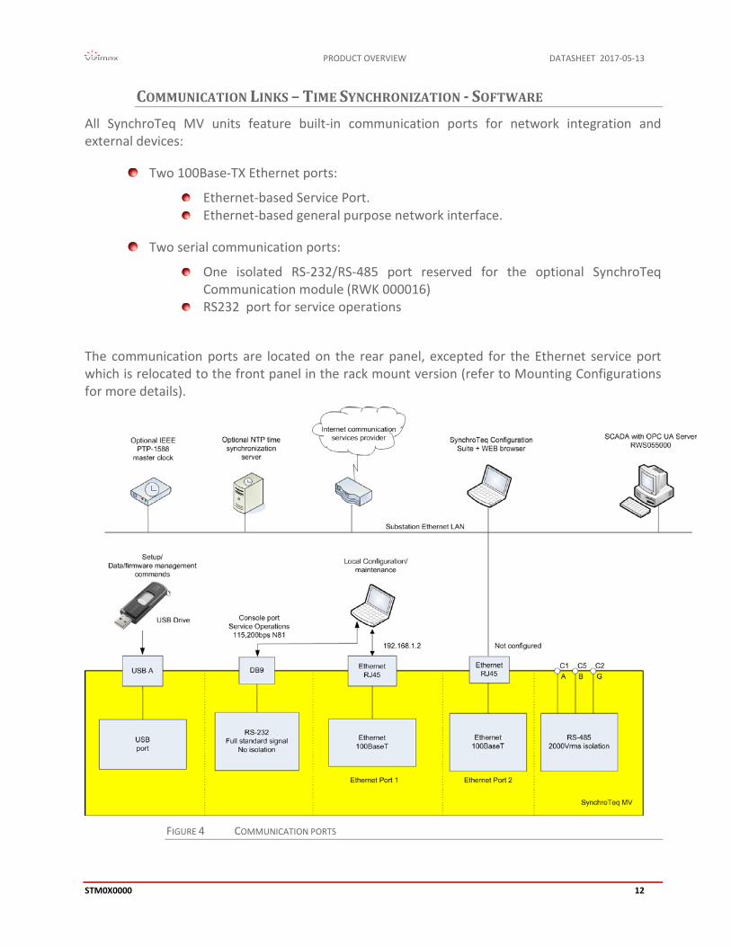
COMMUNICATION LINKS – TIME SYNCHRONIZATION - SOFTWARE All SynchroTeq MV units feature built-in communication ports for network integration and external devices:
Two 100Base-TX Ethernet ports:
Ethernet-based Service Port. Ethernet-based general purpose network interface.
Two serial communication ports:
One isolated RS-232/RS-485 port reserved for the optional SynchroTeq Communication module (RWK 000016)
RS232 port for service operations
The communication ports are located on the rear panel, excepted for the Ethernet service port which is relocated to the front panel in the rack mount version (refer to Mounting Configurations for more details).
FIGURE 4 COMMUNICATION PORTS
DATASHEET 2017-05-13 PRODUCT OVERVIEW
13 STM0X0000
TIME SYNCHRONIZATION
SynchroTeq MV time synchronization can be achieved with either:
PTP-1588 (IEEE Standard Precision Time Protocol) service over the Ethernet network. Supported profile is: ‘’PTP/IEEE-1588v2 UDP/IPv4, Multicast, End-to-End/Peer-to-Peer, Slave Only’’.
IRIG-B time synchronization protocol using the optional RWC0Y0001 module over either:
BNC connector with a compliant IEC 60044-8 TTL signal Fiber optic ST type connector with a compliant IEC 61869-9 signal
The IRIG-B supported formats are:
IRIG-B000/B004 IEEE C37.118 IRIG-B000/B004 IEEE-1344 IRIG-B003
NTP (Network Time Protocol) service over the Ethernet network
Protocol using the optional SynchroTeq Communication module RWK000016.
Any one of these approaches allows to time stamp recorded operational events for remote data analysis.
FRONT PANEL / LOCAL HMI - REMOTE CONTROL
SynchroTeq MV can be managed locally (front panel and built-in HMI) and/or remotely through either:
The SynchroTeq web-based operation interface (requires a web-browser) Local PC computers/servers with optional licenses of the Vizimax Unified
Communication Services (RWS 055000) Remote PC computers/servers with optional licenses of the Vizimax Unified
Communication Services (RWS 065000) Substation automation protocols: requires the optional SynchroTeq Communication
Module (RWK 000016) Dry contacts (commands) and relay outputs (statuses).
PRODUCT OVERVIEW DATASHEET 2017-05-13
STM0X0000 14
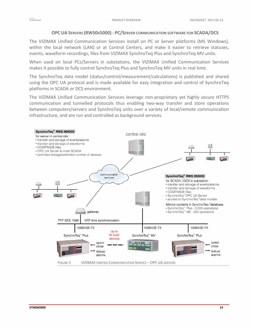
OPC UA SERVERS (RWS0X5000) - PC/SERVER COMMUNICATION SOFTWARE FOR SCADA/DCS
The VIZIMAX Unified Communication Services install on PC or Server platforms (MS Windows), within the local network (LAN) or at Control Centers, and make it easier to retrieve statuses, events, waveform recordings, files from VIZIMAX SynchroTeq Plus and SynchroTeq MV units.
When used on local PCs/Servers in substations, the VIZIMAX Unified Communication Services makes it possible to fully control SynchroTeq Plus and SynchroTeq MV units in real time.
The SynchroTeq data model (status/control/measurement/calculations) is published and shared using the OPC UA protocol and is made available for easy integration and control of SynchroTeq platforms in SCADA or DCS environment.
The VIZIMAX Unified Communication Services leverage non-proprietary yet highly secure HTTPS communication and tunnelled protocols thus enabling two-way transfer and store operations between computers/servers and SynchroTeq units over a variety of local/remote communication infrastructure, and are run and controlled as background services.
FIGURE 5 VIZIMAX UNIFIED COMMUNICATION SERVICE – OPC UA SERVERS
DATASHEET 2017-05-13 PRODUCT OVERVIEW
15 STM0X0000
The VIZIMAX Unified Communication Services allow for:
Transfer and store of statuses, events/alarms, waveform recordings and COMTRADE files from a limited (RWS055000) or an unlimited (RWS065000) number of SynchroTeq Plus and SynchroTeq MV units over IP-based communication networks.
Automatic download and archive of SynchroTeq Plus and SynchroTeq MV contents. Data contents from limited (RWS055000) or unlimited (RWS065000) numbers of switching events (SynchroTeq Plus and SynchroTeq MV) are collected and stored. In substations (RWS055000) data contents mirror the current contents of local SynchroTeq Plus and SynchroTeq MV units. In Control Centers/Central Sites (RWS065000) the stored data volumes will be only capped by the available storage capacity.
Seamless integration of SynchroTeq Plus and SynchroTeq MV data models in central SCADA or HMI solutions in control rooms through OPC UA Server interface and rich data management features allowing for real-time control, exchange, visualization and event generation from statuses, commands, parameters, set points, calculated data.
The most appropriate communication and data refresh rate with respect to the available network infrastructure and performances (on-demand/manual, timed, scheduled).
Please contact your VIZIMAX representative for more details on the VIZIMAX Unified Communication Services software (RWS055000 and RWS065000).
SYNCHROTEQ COMMUNICATION MODULE (OPTION RWK000016)
For application requiring substation protocol such as DNP3, Modbus, IEC 60870-5-101 & -104 or IEC 61850 protocols, VIZIMAX offers an optional SynchroTeq Communication Module (RWK000016).
Please contact your VIZIMAX representative for more details on the SynchroTeq Communication Module (RWK000016).
PRODUCT OVERVIEW DATASHEET 2017-05-13
STM0X0000 16
SYNCHROTEQ CONFIGURATION SUITE AND WEB INTERFACE The SynchroTeq Configuration Suite is a user interface for configuring and operating the SynchroTeq product family. This multi-language software is composed of the following components:
PC based configuration tool software for operation parameters (SynchroTeq Configurator);
VIZIMAX Event Analyzer waveform viewer, which displays the waveform captured by SynchroTeq (COMTRADE format) for operation and functional analysis;
USB port driver for the SynchroTeq product family; Documentation in PDF format
The SynchroTeq Configurator is used to customize the operation of the SynchroTeq MV and its Web interface using system and application configuration files. It supports both offline and online modes of operation and provides features to exchange these configuration files with the SynchroTeq MV unit. Typically, the configuration files are designed and managed offline on a maintenance PC and are uploaded to the SynchroTeq MV as part of the system commissioning.
The VIZIMAX Event Analyzer is a COMTRADE compatible enhanced waveform viewer that displays the waveforms and the C/B operation simultaneously.
SYNCHROTEQ WEB INTERFACE
The unit status, alarms, readings values and event list can be displayed on any PC using a Web browser such as Internet Explorer or Firefox. The SynchroTeq MV Web interface is secured (https://) and access is granted only to authenticated users.
The SynchroTeq Web interface is dedicated for remote operation, control and analysis of the SynchroTeq units. The Web interface offers several dedicated panels:
Dashboard: This page displays real time status of the SynchroTeq unit, the circuit breaker and the load.
Details: This page provides access to detailed statuses, including the SynchroTeq and C/B alarms and the C/B operating time predictions and electrical wear information.
Events: List of the most recent 500 events recorded and stored in the SynchroTeq MV. Snapshot: List of the most recent waveform captures manually triggered by the user. System: System page used to manage the SynchroTeq configuration files and provides
hardware information.

DATASHEET 2017-05-13 PRODUCT OVERVIEW
17 STM0X0000
EVENTS AND WAVEFORM RECORDING
At each switching operation, SynchroTeq MV records current and voltage waveforms including the C/B interface signals (52a/Trip/Close/inputs/commands) over a period of 1250 ms (250 ms pre-trigger). These waveforms are part of the events list which includes alarms and operations performed on the unit (for example, alarm reset, in/out of service). Each event includes the SynchroTeq MV’s complete status and operating environment to allow for detailed further analysis. The SynchroTeq MV has a memory capacity of 500 events, including waveforms.
FIGURE 6 VIZIMAX EVENT ANALYZER

PRODUCT OVERVIEW DATASHEET 2017-05-13
STM0X0000 18
SYNCHROTEQ MV CONNECTORS AND HMI IDENTIFICATION
BACK PANEL CONNECTORS IDENTIFICATION
FRONT PANEL USER INTERFACE
(Panel mount configuration shown here)

DATASHEET 2017-05-13 TECHNICAL SPECIFICATIONS
19 STM0X0000
TECHNICAL SPECIFICATIONS
COMPLIANCE AND CERTIFICATIONS
TEST TYPE
Test type Standard Value
Operating Temperature IEC 68-2-1 and IEC 68-2-2 -40°C to +85°C (*see note)
Maximum Relative humidity (R.H.) IEC 68-2-30 95 % without condensation
IP Rating IEC 60529 IP30
Maximum Altitude IEC 61010-1 2000 m
Pollution Degree IEC 61010-1 Level2
Mechanical resistance to vibrations
Performance IEC 60255-21-1 Class 2
Endurance IEC 60255-21-1 Class 1
Dielectric withstand AC Inputs and I/Os IEC 60255-5 2200 V ac, 1 sec
Communication IEC 60255-5 1650 V ac, 1 sec
Impulse voltage withstand IEC 60255-5 5 kV
Electrostatic discharge (ESD)
Air discharge IEC 61000-4-2 15 kV
Direct contact discharge IEC 61000-4-2 8 kV
Damped Oscillatory Wave (1MHz burst)
Common mode IEC 60255-22-1 2.5 kV
Differential mode 1.0 kV
Fast transients (bursts) IEC 60255-22-4 Level 4
RF Immunity
IEC 61000-4-3 20 V/m, from 80 MHz to 1 GHz
IEC 60255-26 Spot Frequencies: 80 MHz to 2150 MHz
ANSI/IEEE 1613 10 V/m, from 1.4 GHz to 2.7 GHz
SN62. 1008-1 3 V/m, from 5.15 GHz to 5.75 GHz
Conducted disturbance immunity IEC 61000-4-6 150 kHz to 80 MHz
RF emissions CISPR 11, CISPR 22, FCC Class A
Safety IEC 61010-1, 3rd edition ISO 14971 : 2012
Safety for measurement, control, and laboratory use
*See Temperature Test Performances below
TECHNICAL SPECIFICATIONS DATASHEET 2017-05-13
STM0X0000 20
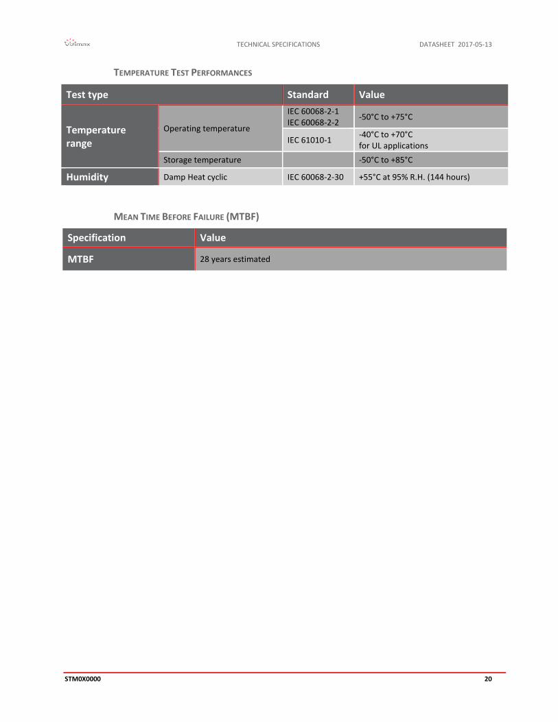
TEMPERATURE TEST PERFORMANCES
Test type Standard Value
Temperature range
Operating temperature
IEC 60068-2-1 IEC 60068-2-2 -50°C to +75°C
IEC 61010-1 -40°C to +70°C for UL applications
Storage temperature -50°C to +85°C
Humidity Damp Heat cyclic IEC 60068-2-30 +55°C at 95% R.H. (144 hours)
MEAN TIME BEFORE FAILURE (MTBF)
Specification Value
MTBF 28 years estimated

DATASHEET 2017-05-13 TECHNICAL SPECIFICATIONS
21 STM0X0000
POWER SUPPLY The power supply is set in factory according to the ordering option.
Parameter Value
Power supply rating (24 V) 20 V dc - 35 V dc
Power supply rating (48 V) 36 V dc - 72 V dc
Power supply rating (110 V) 70 V dc – 140 V dc
Power supply rating (125 V) 100 V dc - 140 V dc
Power supply rating (220 V) 180 V dc - 280 V dc
Rated power 15W max. (typical 9W, 0.07 A @ 125 V dc ) – Idle 6W
Connector Phoenix MSTB 5.08mm
Isolation 3000V during 1 second
Fuse Time delay, 2 x 2 A (not user serviceable)
Voltage interrupt (max) 100ms @ 100%
ACCESSORY POWER SUPPLY OUTPUT
SynchroTeq MV offers an accessory power supply output rated at 24Vdc, 3W maximum and internally referred to the chassis (PE). This power supply output (connector A) is reserved for feeding power to the optional SynchroTeq Communication Module (RWK000016).
Parameter Value
Power supply rating (24 V) 3 Watts maximum recommended load
This accessory power supply output is not available on the SynchroTeq MV models with DC power supply input NOTE:ratings of 24V. In this case, when the optional SynchroTeq Communication Module is necessary, it should be fed from the same power source as the SynchroTeq MV.

TECHNICAL SPECIFICATIONS DATASHEET 2017-05-13
STM0X0000 22
CONTROL AND COMMUNICATION
CONTROLLER
Parameter Value
Main processor 32-bit, 400 MHz high performance ARM processor
OS Linux
Memory 512 MB Flash memory / 128 MB RAM
Real time clock ±3 ppm initial accuracy. Stability is ± 5 ppm across the complete operating temperature range. Autonomy is 36 hours without power (no battery required)
RTC synchronization IRIG-B protocol using the optional RWC0Y0001 module LAN synchronization: NTP or IEEE 1588 (see Note) or SynchroComm (RWK000016)
I/O board controller 32 bits, 168 MHz ARM processor with RTOS. 16 bit ADC.
Field upgrade Field upgradable firmware available from VIZIMAX web site, support section
Several different configurations (profiles) are defined with the PTP-1588 protocol. SynchroTeq MVX and NOTE:SynchroTeq MVR supports version 2 using UDP (layer 3) as defined by: ‘’PTP/IEEE-1588v2 UDP/IPv4, Multicast, End-to-End/Peer-to-Peer, Slave Only’’.
LOCAL USER INTERFACE
Parameter Value Two push buttons (back and front panel)
- Open/Close - In/Out of Service
Seven LEDs (back panel) Service, Circuit breaker position, Communication activity (2x), System status, Alarms and Power.
Five LEDs (front panel) Service, Circuit breaker position, System status, Alarms and Power.
OPTIONAL IRIG-B TIME SYNCHRONIZATION MODULE (RWC0Y0001)
Specification Value
Base precision Better than 10 µs
IRIG-B DCLS (Un-modulated) over Fiber Optic ST type (connector N)
Frequency range : 820 – 850 nanometers Base precision better than 1.0 µs
IRIG-B DCLS (Un-modulated) on BNC BNC type (connector P)
Input impedance : Zin = 500 Ω Input level : 2.5V to 5.0 Vdc Base precision better than 10 µs
Voltage isolation level 500 Vdc
IRIG-B formats (selectable by software)
- IRIG-B000/B004 IEEE-C37.118 (default setting) - IRIG-B000/B004 IEEE-1344 - IRIG-B003

DATASHEET 2017-05-13 TECHNICAL SPECIFICATIONS
23 STM0X0000
COMMUNICATION PORTS
Port Characteristics Value
USB port (back panel)
Interface compatibility 2.0
Maximum speed 480 Mbit/sec
Connector type Type A
Voltage isolation level N/A
100Base-TX Ethernet 1 (Service port)
Interface 10/100 Mbps
Connector RJ-45
Isolation 1500 VRMS
Name Port 1
Function Initial unit configuration and setup
100Base-TX Ethernet 2 (User communication link)
Interface 10/100 Mbps
Connector RJ-45
Isolation 1500 VRMS
Name Port 2
RS-232 Serial Function Console port, service Operations
Connector DB-9 (connector C)
Bit rate 115 kbps
RS-485 Isolated Serial
Function Reserved for SynchroTeq Communication Module link (RWK 000016)
Connector Molex Mini-Fit junior (connector A)
Bit rate 38.4 kbps
Mode
Two wire interface (A-B) with jumper selectable 120 Ω terminations. Reference wire (0V) provided for high common mode voltage capability
Isolation 2000 VRMS

TECHNICAL SPECIFICATIONS DATASHEET 2017-05-13
STM0X0000 24
AC MEASUREMENT INPUTS SynchroTeq MV measures the following AC signals from current and voltage sensors:
Source voltage (VS) Phase A: this measurement is taken from a voltage sensor located on phase A of the source side. This signal is used for the C/B operation synchronization and frequency measurement.
Phase A, B and C load current (IA, IB and IC): these measurements are taken from current sensor located on either side of the switchgear to measure the load current for excessive inrush current detection, switchgear electrical closing time calculation and switchgear opening synchronization (Phase A). These inputs can be connected to either protection or measurement CTs.
Phase A, B and C voltage (VA, VB and VC) SynchroTeq MVX only: these measurements are taken from voltage sensors located on the power transformer’s primary or secondary winding to measure the power transformer voltage in order to calculate the residual flux resulting from transformer de-energization. When energizing the transformer, the residual flux calculation is used to reduce the inrush current to a magnitude comparable to the magnetization current by automatically adjusting the closing angle. For capacitive load switching applications (partially discharge capacitor bank or harmonic filters, cables) with, or without, fast switching capability, these measurements are used to measure phase A, B and C of the source side.
DATASHEET 2017-05-13 TECHNICAL SPECIFICATIONS
25 STM0X0000
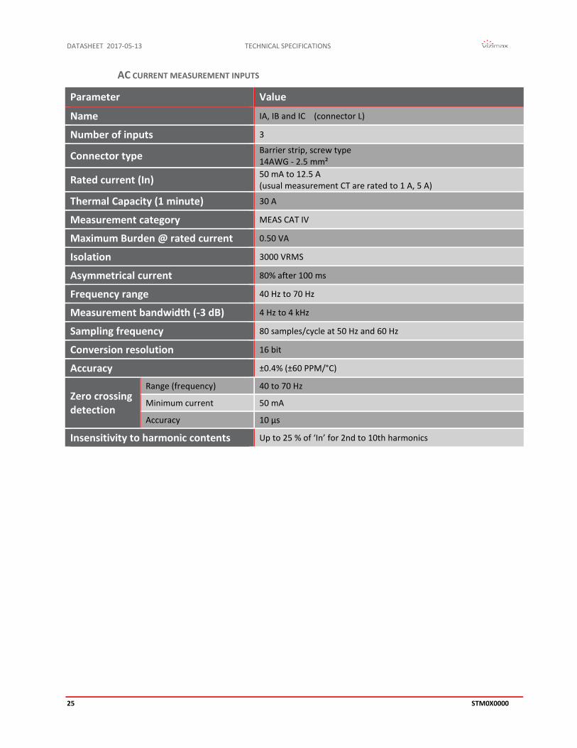
AC CURRENT MEASUREMENT INPUTS
Parameter Value
Name IA, IB and IC (connector L)
Number of inputs 3
Connector type Barrier strip, screw type 14AWG - 2.5 mm²
Rated current (In) 50 mA to 12.5 A (usual measurement CT are rated to 1 A, 5 A)
Thermal Capacity (1 minute) 30 A
Measurement category MEAS CAT IV
Maximum Burden @ rated current 0.50 VA
Isolation 3000 VRMS
Asymmetrical current 80% after 100 ms
Frequency range 40 Hz to 70 Hz
Measurement bandwidth (-3 dB) 4 Hz to 4 kHz
Sampling frequency 80 samples/cycle at 50 Hz and 60 Hz
Conversion resolution 16 bit
Accuracy ±0.4% (±60 PPM/°C)
Zero crossing detection
Range (frequency) 40 to 70 Hz
Minimum current 50 mA
Accuracy 10 µs
Insensitivity to harmonic contents Up to 25 % of ‘In’ for 2nd to 10th harmonics

TECHNICAL SPECIFICATIONS DATASHEET 2017-05-13
STM0X0000 26
AC SOURCE VOLTAGE MEASUREMENT INPUT (VS)
Parameter Value
Name VS (connector K)
Number of input 1
Connector type Phoenix MSTB 5.08mm, pluggable screw type AWG 13-24 (2.5 mm2 – 0.2 mm2)
Rated voltage (Vn) 10 V ac to 167 V ac (usual measurement PT are rated to 69 V ac, 110 V ac, 120 V ac)
Thermal capacity (1 minute) 300 V ac
Measurement category MEAS CAT IV
Maximum Burden 0.10 VA
Isolation 2000 VRMS
Frequency range 40Hz to 70 Hz
Measurement bandwidth (-3 dB) DC to 4 kHz
Sampling frequency 80 samples/cycle at 50 Hz and 60 Hz
Conversion resolution 16 bit
Accuracy ±0.3% (± 40 PPM/°C)
Zero crossing detection
Range (frequency) 40 to 70 Hz
Minimum voltage 60% of Vn or 40 V ac depending of ‘DynamicZX’ parameter setting
Accuracy 10 µs
Insensitivity to harmonic contents Up to 50 % of Vn for 2nd to 10th harmonics
Input Impedance 5100 KΩ Caution: units manufactured before November 1st, 2016 have VS input impedance of 1000 KΩ only and cannot be used with voltage capacitive divider.
Common Mode Voltage Range 700 V ac
DATASHEET 2017-05-13 TECHNICAL SPECIFICATIONS
27 STM0X0000
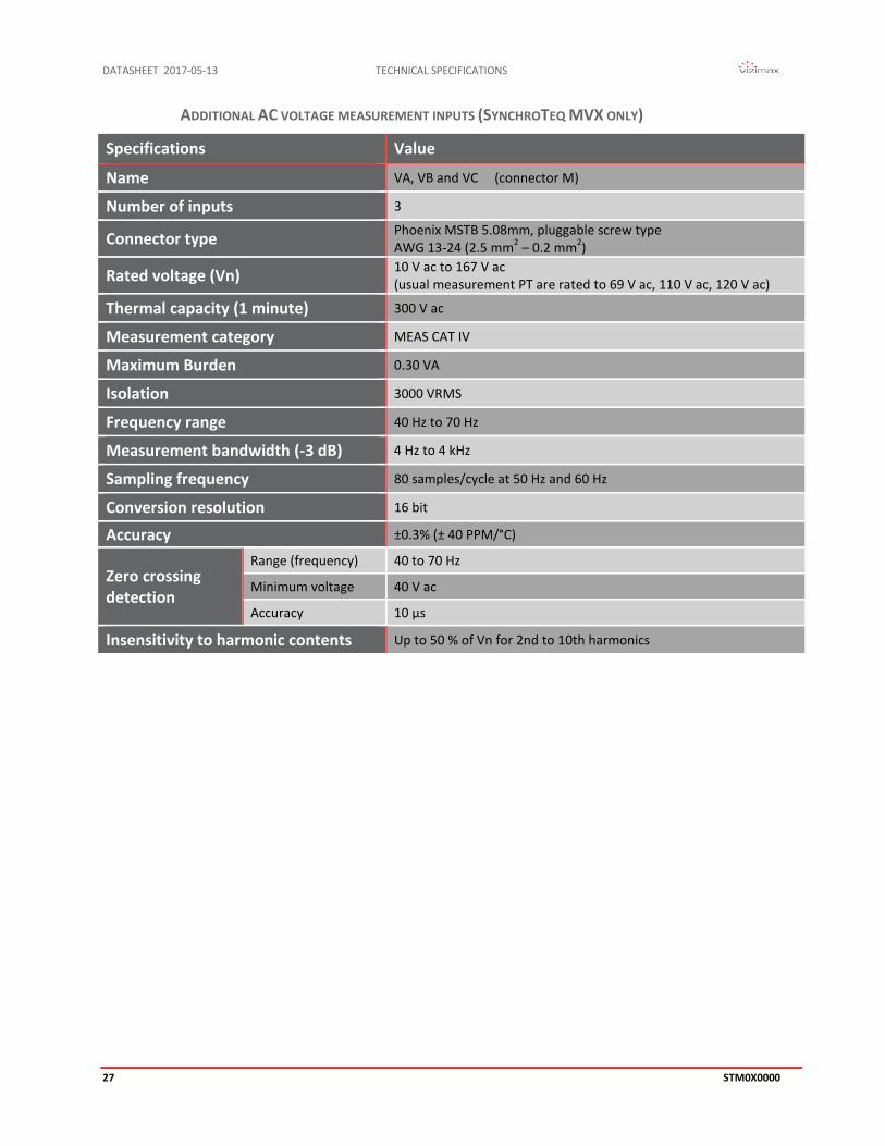
ADDITIONAL AC VOLTAGE MEASUREMENT INPUTS (SYNCHROTEQ MVX ONLY)
Specifications Value
Name VA, VB and VC (connector M)
Number of inputs 3
Connector type Phoenix MSTB 5.08mm, pluggable screw type AWG 13-24 (2.5 mm2 – 0.2 mm2)
Rated voltage (Vn) 10 V ac to 167 V ac (usual measurement PT are rated to 69 V ac, 110 V ac, 120 V ac)
Thermal capacity (1 minute) 300 V ac
Measurement category MEAS CAT IV
Maximum Burden 0.30 VA
Isolation 3000 VRMS
Frequency range 40 Hz to 70 Hz
Measurement bandwidth (-3 dB) 4 Hz to 4 kHz
Sampling frequency 80 samples/cycle at 50 Hz and 60 Hz
Conversion resolution 16 bit
Accuracy ±0.3% (± 40 PPM/°C)
Zero crossing detection
Range (frequency) 40 to 70 Hz
Minimum voltage 40 V ac
Accuracy 10 µs
Insensitivity to harmonic contents Up to 50 % of Vn for 2nd to 10th harmonics
TECHNICAL SPECIFICATIONS DATASHEET 2017-05-13
STM0X0000 28
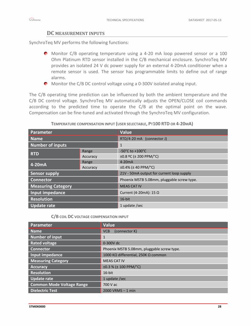
DC MEASUREMENT INPUTS SynchroTeq MV performs the following functions:
Monitor C/B operating temperature using a 4-20 mA loop powered sensor or a 100 Ohm Platinum RTD sensor installed in the C/B mechanical enclosure. SynchroTeq MV provides an isolated 24 V dc power supply for an external 4-20mA conditioner when a remote sensor is used. The sensor has programmable limits to define out of range alarms.
Monitor the C/B DC control voltage using a 0-300V isolated analog input.
The C/B operating time prediction can be influenced by both the ambient temperature and the C/B DC control voltage. SynchroTeq MV automatically adjusts the OPEN/CLOSE coil commands according to the predicted time to operate the C/B at the optimal point on the wave. Compensation can be fine-tuned and activated through the SynchroTeq MV configuration.
TEMPERATURE COMPENSATION INPUT (USER SELECTABLE, PT100 RTD OR 4-20MA)
Parameter Value Name RTD/4-20 mA (connector J)
Number of inputs 1
RTD Range -50°C to +100°C Accuracy ±0.8 ºC (± 200 PPM/°C)
4-20mA Range 4-20mA Accuracy ±0.4% (± 40 PPM/°C)
Sensor supply 21V - 50mA output for current loop supply
Connector Phoenix MSTB 5.08mm, pluggable screw type.
Measuring Category MEAS CAT IV
Input impedance Current (4-20mA): 15 Ω
Resolution 16-bit
Update rate 1 update /sec
C/B COIL DC VOLTAGE COMPENSATION INPUT
Parameter Value Name VCB (connector K) Number of input 1 Rated voltage 0-300V dc Connector Phoenix MSTB 5.08mm, pluggable screw type. Input impedance 1000 KΩ differential, 250K Ω common Measuring Category MEAS CAT IV Accuracy ±0.3 % (± 100 PPM/°C) Resolution 16-bit Update rate 1 update /sec Common Mode Voltage Range 700 V ac Dielectric Test 2000 VRMS – 1 min

DATASHEET 2017-05-13 TECHNICAL SPECIFICATIONS
29 STM0X0000
DIGITAL INPUTS / OUTPUTS
DIGITAL INPUTS
SynchroTeq MV provides 10 opto-isolated digital inputs distributed in two isolated groups:
Three inputs for C/B position (52a contacts) Two inputs for the control of the C/B (OPEN/CLOSE commands) Five programmable inputs for C/B monitoring and commands with separate returns
Parameter Value
Name IN 1 to 10 (connectors G-H)
Number of inputs 10 (6+4)
Maximum input voltage (24V power supply) 30 V dc, (detection threshold 16 V dc)
Maximum input voltage (48V power supply) 72 V dc, (detection threshold 28 V dc)
Maximum input voltage (110V power supply) Max: 140 V dc Threshold: 52a inputs: 56 V dc Threshold: all other inputs: 69 V dc (±10%)
Maximum input voltage (125V power supply) Max: 140 V dc Threshold: 52a inputs: 66 V dc Threshold: all other inputs: 74 V dc (±10%)
Maximum input voltage (220V power supply) Max: 280 V dc Threshold: 52a inputs: 113 V dc Threshold: all other inputs: 137 V dc (±10%)
Isolation Opto-coupler, 2000 VRMS
Measuring Category MEAS CAT IV
Burden 2 mA to 5 mA
Maximum Hardware response Time 0.10 ms at nominal voltage 1.00 ms at 80% of nominal voltage
Software Filter Programmable, 1 ms increments up to 250ms
Connector Phoenix MSTB 5.08mm, pluggable screw type.
Digital inputs operating range is set according to the ordered power supply operating range. NOTE:
TECHNICAL SPECIFICATIONS DATASHEET 2017-05-13
STM0X0000 30
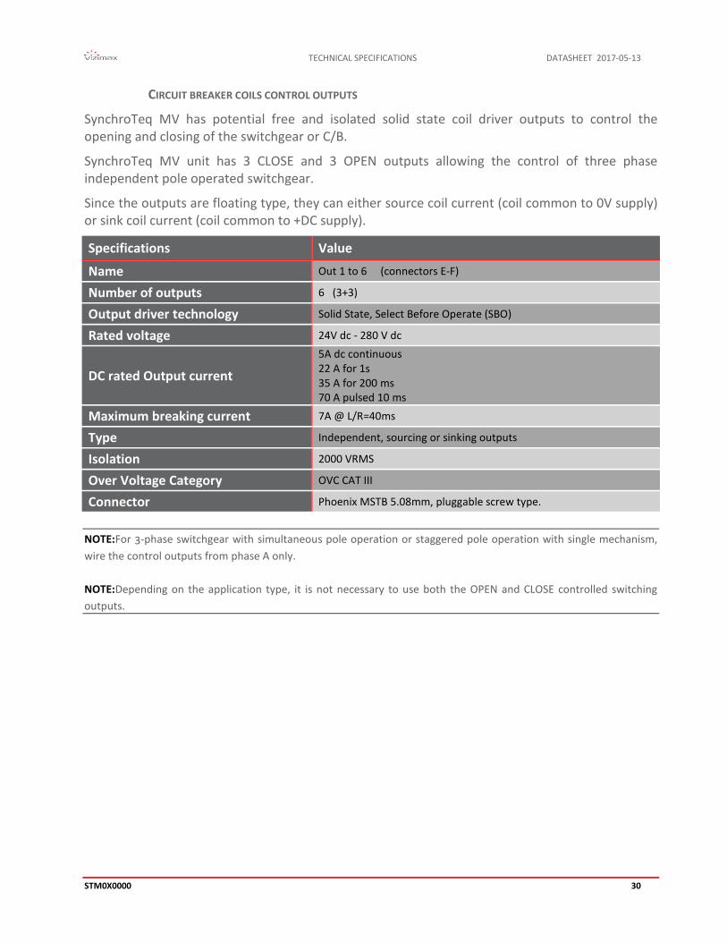
CIRCUIT BREAKER COILS CONTROL OUTPUTS
SynchroTeq MV has potential free and isolated solid state coil driver outputs to control the opening and closing of the switchgear or C/B.
SynchroTeq MV unit has 3 CLOSE and 3 OPEN outputs allowing the control of three phase independent pole operated switchgear.
Since the outputs are floating type, they can either source coil current (coil common to 0V supply) or sink coil current (coil common to +DC supply).
Specifications Value
Name Out 1 to 6 (connectors E-F)
Number of outputs 6 (3+3)
Output driver technology Solid State, Select Before Operate (SBO)
Rated voltage 24V dc - 280 V dc
DC rated Output current
5A dc continuous 22 A for 1s 35 A for 200 ms 70 A pulsed 10 ms
Maximum breaking current 7A @ L/R=40ms
Type Independent, sourcing or sinking outputs
Isolation 2000 VRMS
Over Voltage Category OVC CAT III
Connector Phoenix MSTB 5.08mm, pluggable screw type.
For 3-phase switchgear with simultaneous pole operation or staggered pole operation with single mechanism, NOTE:wire the control outputs from phase A only.
Depending on the application type, it is not necessary to use both the OPEN and CLOSE controlled switching NOTE:outputs.

DATASHEET 2017-05-13 TECHNICAL SPECIFICATIONS
31 STM0X0000
SIGNALIZATION RELAY OUTPUTS
SynchroTeq MV offers 4 dry contacts digital outputs for alarming and status signalization. The outputs are arranged in two isolated groups with the following functions:
R1: Out of service/Fatal alarm, form A R2: C/B Temperature or C/B DC control voltage monitoring alarm, form A R3: C/B Operation limits and inrush current alarm, form C R4: System OK (watchdog), form C. The NC contact is used to indicate that the system
is failed.
Specifications Value
Number of outputs R1 to R4 2x form A and 2x form C dry contact outputs (connector D)
Type: Electromechanical relays
Maximum steady AC current 3 A maximum at 250 V ac
Maximum steady DC current 0.3 A maximum at 250 V dc
Contact ratings: 250 V ac, 300 V dc
Contact breaking capacity: 10 A at 250 V ac 8 A @ 30 V, 0.5 A @125 V, 0.3 A at 250 V dc
Isolation: 5000 VRMS (coil to contacts)
Over Voltage Category OVC CAT III
Connector: Phoenix MSTB 5.08mm, pluggable screw type.
TECHNICAL SPECIFICATIONS DATASHEET 2017-05-13
STM0X0000 32
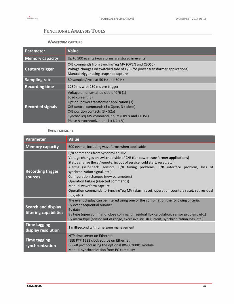
FUNCTIONAL ANALYSIS TOOLS
WAVEFORM CAPTURE
Parameter Value
Memory capacity Up to 500 events (waveforms are stored in events)
Capture trigger C/B commands from SynchroTeq MV (OPEN and CLOSE) Voltage changes on switched side of C/B (for power transformer applications) Manual trigger using snapshot capture
Sampling rate 80 samples/cycle at 50 Hz and 60 Hz
Recording time 1250 ms with 250 ms pre-trigger
Recorded signals
Voltage on unswitched side of C/B (1) Load current (3) Option: power transformer application (3) C/B control commands (3 x Open, 3 x close) C/B position contacts (3 x 52a) SynchroTeq MV command inputs (OPEN and CLOSE) Phase A synchronization (1 x I, 1 x V)
EVENT MEMORY
Parameter Value
Memory capacity 500 events, including waveforms when applicable
Recording trigger sources
C/B commands from SynchroTeq MV Voltage changes on switched side of C/B (for power transformer applications) Status change (local/remote, in/out of service, cold start, reset, etc.) Alarms (self-check, sensors, C/B timing problems, C/B interface problem, loss of synchronization signal, etc.) Configuration changes (new parameters) Operation failure (rejected commands) Manual waveform capture Operation commands to SynchroTeq MV (alarm reset, operation counters reset, set residual flux, etc.)
Search and display filtering capabilities
The event display can be filtered using one or the combination the following criteria: By event sequential number By date By type (open command, close command, residual flux calculation, sensor problem, etc.) By alarm type (sensor out of range, excessive inrush current, synchronization loss, etc.)
Time tagging display resolution
1 millisecond with time zone management
Time tagging synchronization
NTP time server on Ethernet IEEE PTP 1588 clock source on Ethernet IRIG-B protocol using the optional RWC0Y0001 module Manual synchronization from PC computer
DATASHEET 2017-05-13 MOUNTING CONFIGURATIONS
33 STM0X0000
MOUNTING CONFIGURATIONS
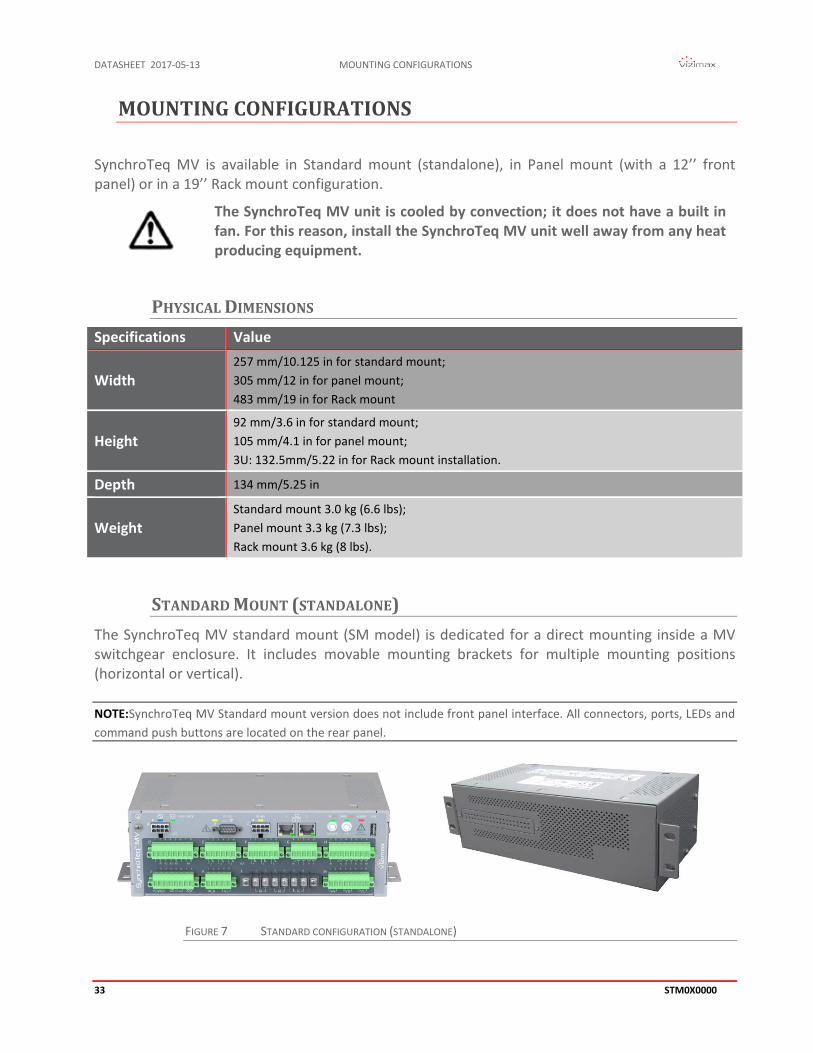
SynchroTeq MV is available in Standard mount (standalone), in Panel mount (with a 12’’ front panel) or in a 19’’ Rack mount configuration.
The SynchroTeq MV unit is cooled by convection; it does not have a built in fan. For this reason, install the SynchroTeq MV unit well away from any heat producing equipment.
PHYSICAL DIMENSIONS Specifications Value
Width 257 mm/10.125 in for standard mount; 305 mm/12 in for panel mount; 483 mm/19 in for Rack mount
Height 92 mm/3.6 in for standard mount; 105 mm/4.1 in for panel mount; 3U: 132.5mm/5.22 in for Rack mount installation.
Depth 134 mm/5.25 in
Weight Standard mount 3.0 kg (6.6 lbs); Panel mount 3.3 kg (7.3 lbs); Rack mount 3.6 kg (8 lbs).
STANDARD MOUNT (STANDALONE) The SynchroTeq MV standard mount (SM model) is dedicated for a direct mounting inside a MV switchgear enclosure. It includes movable mounting brackets for multiple mounting positions (horizontal or vertical).
SynchroTeq MV Standard mount version does not include front panel interface. All connectors, ports, LEDs and NOTE:command push buttons are located on the rear panel.
FIGURE 7 STANDARD CONFIGURATION (STANDALONE)

MOUNTING CONFIGURATIONS DATASHEET 2017-05-13
STM0X0000 34
FIGURE 8 STANDARD MOUNT – HORIZONTAL
FIGURE 9 STANDARD MOUNT – VERTICAL

DATASHEET 2017-05-13 MOUNTING CONFIGURATIONS
35 STM0X0000
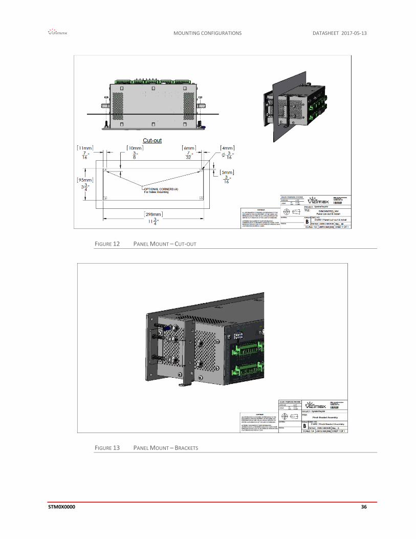
PANEL MOUNT The SynchroTeq MV Panel Mount (PM model) is for mounting to a metallic panel or swing door inside a breaker control or a switchgear enclosure. It includes mounting brackets and dual control panels (Front and rear). The panel foot print is 105 x 305 mm (4.1 x 12.0 in).
FIGURE 10 PANEL MOUNT
FIGURE 11 PANEL MOUNT DIMENSIONS
MOUNTING CONFIGURATIONS DATASHEET 2017-05-13
STM0X0000 36
FIGURE 12 PANEL MOUNT – CUT-OUT
FIGURE 13 PANEL MOUNT – BRACKETS

DATASHEET 2017-05-13 MOUNTING CONFIGURATIONS
37 STM0X0000
RACK MOUNT The SynchroTeq MV rack mount (RM model) is installed on an EIA 482.6 mm (19 in) rack in the MV switchgear. Panel size: 3U standard panel (5.219 x 19 in).
In this configuration, the Ethernet service port is relocated on the front panel.
FIGURE 14 19’’ RACK MOUNT CONFIGURATION
A DIN rail (120mm / 4.8 in) is provided on the rear panel to mount terminal blocks or IED accessories.
ORDERING INFORMATION DATASHEET 2017-05-13
STM0X0000 38
ORDERING INFORMATION
STM010000 SynchroTeq MVR base unit (Smart Coding to be confirmed at order) for the controlled switching of shunt reactors, discharged capacitor banks, harmonic filters, power cables, power transformers, all based on fixed switching angle strategies.
STM030000 SynchroTeq MVX base unit (Smart Coding to be confirmed at order) for three-
phase MV power transformer switching applications with residual flux calculation and partially discharged capacitor banks and filters and cables with the acquisition of residual charges.
To select ordering options such as, mounting configuration, or IRIG-B synchronization or power supply voltage, please refer to the ‘smart coding’ document ‘STM0x0000-SC’.
To access the smart coding document, please register to the VIZIMAX web site https://www.VIZIMAX.com/ and then download the document.
VIZIMAX also offers commissioning and training services: for more details please contact us.
Options:
RWS055000 SynchroTeq Unified Communication Services in substations: Data Transfer and OPC UA Server. For up to ten (10) SynchroTeq Plus/MV units on substation's LAN. Automatic transfer and mirroring of event/waveform/COMTRADE files. OPC UA Server interface for SCADA/DCS
RWS065000 SynchroTeq Unified Communication Services in Central Sites: Data Transfer and
OPC UA Server. Accommodates an unlimited number of remote SynchroTeq Plus/MV units and automatic transfer and mirroring of event/waveform/COMTRADE files. OPC UA Server interface and rich tools for SCADA/HMI in central sites.
These specifications are subject to change without prior notice. NOTE:

DATASHEET 2017-05-13 ORDERING INFORMATION
39 STM0X0000
Support contact: [email protected] www.VIZIMAX.com/support
Vizimax, the Vizimax logo, RightWON, WiseWON, SynchroTeq, SynchroTeq Plus and the RightWON icons are trademarks or registered trademarks of Vizimax, Inc. in Canada, the United States and other jurisdictions. All other trademarks, registered trademarks and service marks are the property of their respective owners.
V-FOPR03-011en (2016-03-22)