Embed Size (px)
Citation preview

Synchronization and handoff management schemesfor wireless multimedia systems q
Azzedine Boukerche *, Sungbum Hong, Tom Jacob
Department of Computer Science, University of North of Texas, P.O. Box 311366, Denton, TX 76203, USA
Abstract
This paper presents handoff management schemes for synchronization algorithms for wireless multimedia systems.
The synchronization and handoff management schemes allow mobile hosts to receive time-dependant multimedia
streams without delivery interruption while moving from one cell to another. They also maintain the correct ordering of
the media components, through the execution of the wireless multimedia application by a means of timestamped
messages passed among mobile hosts, base stations and servers. The timestamp values are used to compute the delay for
each multimedia unit for each server. Furthermore, the proposed schemes always search for a quasi-receiver among the
base stations with which the mobile hosts can communicate to synchronize multimedia units. We discuss the algorithms
and present a set of simulation experiments that evaluate the performance of our schemes, using message complexity
and buffer usage at each frame arrival time. Our results indicate that our schemes exhibit no underflow or overflow
within the bounded delivery time.
� 2002 Published by Elsevier Science B.V.
Keywords: Distributed algorithm; Synchronization; Mobile multimedia; Wireless communications; End-to-end protocol
1. Introduction
Advances in wireless technology that allow
mobile clients to carry multimedia traffic have
served as an impetus for the emergence of newapplications like wireless digital news services and
video on demand. The multimedia units can be
time dependent or non-time-dependent objects.
Video and voice streams are examples of time-
dependent objects. In this paper, we examine
synchronization and handoff management schemes
for time-dependent multimedia streams.
The basic abstraction for a time-constrained
media element is a timed stream of media com-ponents. The term ‘‘media component’’ means a
video frame or audio sample. These components
normally must be kept in temporal order when
they are being played. The process of maintaining
this ordering of the media components is referred
to as multimedia synchronization [2]. There are
two timing aspects for time-constrained elements:
(i) intra-media continuity is subject to a real timeconstraint in handling media elements; and (ii)
inter-media synchronization is subject to temporal
q This work was supported by Texas Advanced Research
Program Grant ARP/ATP-003594-0092-2001.* Corresponding author. Fax: +1-940-565-2799.
E-mail addresses: [email protected] (A. Boukerche),
[email protected] (S. Hong), [email protected] (T. Jacob).
1389-1286/03/$ - see front matter � 2002 Published by Elsevier Science B.V.
PII: S1389-1286 (02 )00422-X
Computer Networks 41 (2003) 347–362
www.elsevier.com/locate/comnet

correlation during a playback of media elements
[13].
The synchronization problem under a combi-
nation of wireless/wired networks is more com-
plicated than the problem for wired networks
because wireless networks must use a base stationto deliver packets and have much less resources
[5]. However, studying a combination of wired/
wireless networks is valuable because they can
provide a richer multimedia environment for
mobile users than can pure (cellular) wireless sys-
tems.
Recall that a cellular wireless communication
network [7] has its coverage area partitionedinto cells, where each cell is served by an antenna
or base station (BS). Cell size and shape depend on
signal strength and the presence of obstacles to
signal propagation. As shown in Fig. 1, a set of
base stations is controlled by a base station con-
troller (BSC). Several BSCs are connected to a
mobile switching center (MSC), which manages all
calls in a large geographical area, doing call setupand handoff. The links between the base stations
and mobile hosts are wireless, whereas those be-
tween the base stations and their MSCs are wired.
This architecture allows a base station to com-
municate with many mobile hosts concurrently.
Each mobile host can move from one base station
to another. Even though the synchronization
problem for distributed stored multimedia streamsbased on fixed networks has been well studied
[1,2], to the best of our knowledge, little has been
done for wireless multimedia systems [3].
1.1. Related work
Most of the research work to synchronize play-
out and delivery of distributed stored multimedia
streams has been done for wired networks. In thispaper, we review research work related to the
multimedia synchronization problem. Interested
readers may wish to consult [1,2,8,16] for multi-
media synchronization work done in a wired net-
work.
Most wireless multimedia services still need
more network resources than are currently avail-
able on a wireless network. Depending on resourcesufficiency for wireless networks, access speed
and mobility can vary, so that synchronization
schemes must be developed differently to fit vary-
ing network conditions. In this section, we shall
review the synchronization schemes for several
wireless network types.
A wireless local area network (LAN) provides
wide bandwidth within a geographical area andsupports low speed mobility. In [14], four lip
synchronization schemes are studied with single
transport streams. In [15], a set of lip synchroni-
zation schemes is studied with the single-stream
approach, where the performance of the schemes is
measured on a wireless LAN. In all of these
schemes, a single server is used to store multimedia
units for all models.A personal handy phone system (PHS) is a kind
of micro-cellular digital cordless telephone system
that covers a slightly wider geographical area with
moderately better mobility than a wireless LAN,
but covers much less area than a personal com-
munication system (PCS). Kato et al. [9,10] pro-
posed applications of a slide control scheme for
wireless systems. The first paper [9] showed the slidecontrol scheme to be effective when audio and video
streams are transmitted over two wireless channels
for mobile hosts. In the second paper [10], the au-
thors studied the interleaved transmission of audio
and video for wireless multimedia synchronization
as well as a quality of service control scheme.
A bluetooth link connects mobile terminals with
their peripheral equipment over the ISM (Indus-trial, Scientific and Medical) band. Using this
technology, a synchronization scheme has been
studied under interference from other systems [12].Fig. 1. Network with soft handoff.
348 A. Boukerche et al. / Computer Networks 41 (2003) 347–362

1.2. Contributions of this paper
Although distributed synchronizations for
wired multimedia systems have been an area of
extensive research [1,2], to the best of our know-ledge, there are few reported results on the imple-
mentation of synchronization schemes for wireless
(or a combination of wired/wireless) multimedia
systems.
A combination of wired/wireless networks for
multimedia servers differs significantly from wired
networks: (i) in delivering packets for mobile
hosts, all packets must pass through at least onebase station (BS) to reach a mobile host; (ii) a
mobile host (MH) has small memory and small
screen size; (iii) there is low network bandwidth
between a base station and a mobile host; and (iv)
a MH can get several communication channels
from different BSs. Because of such differences,
conventional synchronization strategies for deliv-
ering multimedia units (MMUs) to mobile hostswithin a certain time cannot be applied in the
mixed environment. A single base station must
pass many MMUs and much control information
to mobile hosts, which can cause congestion at the
base station. Because of the small memory and low
bandwidth at a mobile host, this traffic may also
cause mobile host memory underflow or overflow.
A mobile host can move from one cell to another,which means the communication channel can
change. A mobile host can also hold more than
one communication channel in certain areas [6].
In this paper, we propose handoff management
schemes to support the synchronization of multi-
media units (MMU) for wireless and mobile cli-
ents 1 that use base stations as quasi-receivers to
control and ensure the MMUs correct ordering.The schemes are proposed for managing MMUs
so as to deliver them to mobile hosts on time.
Furthermore, our proposed synchronization and
handoff management schemes cope with network
jitter, end-system jitter, clock drift, and changing
network conditions during soft handoff. Hence, our
schemes are suitable both for synchronizing inter-
and intra-streams during playback video and for
re-synchronizing streams in a wireless network. We
also present a set of simulation experiments to
study the performance of our algorithms.
The remainder of the paper is organized as
follows. Section 2 contains a description of thecommunication model we use in this paper. Sec-
tion 3 presents an outline of our multimedia units
synchronization algorithm for wireless multimedia
systems. Section 4 describes our handoff manage-
ment schemes for multimedia units synchroniza-
tion, which we refer to as one-phase and two-phase
schemes. Section 5 provides their proof of cor-
rectness. Section 6 reports simulation experimentsevaluating the performance of our algorithms for
different arrival patterns. Section 7 presents our
conclusions and future research topics.
2. Communication model
In our design, we assume that our system con-
sists of K scalable server nodes, N base station
nodes and L wireless clients (mobile hosts). Gen-
erally, the system contains a variety of servers,
depending on the needs of the mobile hosts. Forinstance, in a video-on-demand system, a video
consists of many video frames that can be divided
into K equal-size parts, called subframes. These
subframes are equally located at K different server
nodes using a technique called subframe stripping
[11]. During a playback, wireless clients conti-
nually receive subframes from a server. Servers
have admission control capability and also canchange the data transfer rate at the mobile host�srequest.
In our model, all mobile hosts get services from
the same set of servers. Their communication is
through base stations, where many servers connect
to each base station, and each base station con-
nects to many mobile hosts. Also at certain times,
two or three base stations can communicate with amobile host simultaneously (see Fig. 1). Because of
this, we need to assign special roles to the base
stations to represent mobile hosts within their
cells. During the handoff period, there should be a
management function that can handle ordering of
MMU arrivals at the base stations.
1 In the sequel, mobile host and mobile client are taken to
mean the same things.
A. Boukerche et al. / Computer Networks 41 (2003) 347–362 349

3. Description of the wireless multimedia synchro-
nization algorithm
In this section, we present the basic ideas of
MoSync, our distributed synchronization algo-rithm for wireless multimedia systems. Unlike
other types of distributed schedulers, the MoSync
algorithm uses three types of nodes: servers, Quasi-
receivers, and receivers. The servers have type
server, the base stations have type quasi-receiver,
and the mobile clients have type receiver. The
mobile hosts (wireless multimedia clients) have the
responsibility to synchronize the multimedia ob-jects received from multimedia servers. Mobile
hosts report the amount of buffer consumed to the
base station that controls the area where they are
located, and they let the base station knows the
differences among multimedia objects� arrival
times. Once a base station collects all information
about the arrival time of each multimedia object, it
calculates the synchronized time for the nextpackets. A scheduler in the server manages the
transfer of the subframes as part of the frames to
the wireless clients on time.
We now describe the basic protocol of MoSync
for each type of hosts to facilitate understanding
the basic ideas of our multimedia synchronization
algorithm.
As illustrated in Fig. 2, MHl requests multime-dia service through BSm from the server Sk. The
base station has three roles: a messenger role, a
filter role, and a quasi-receiver role. The base sta-
tion, acting as a messenger, passes multimedia
packets to mobile clients. As a filter, it sends a
request for packets to servers, and as a quasi-
receiver, it receives only the first packets from the
servers. After that, the multimedia objects are sentdirectly from the senders to the mobile hosts. It
also calculates the synchronization point for each
server, i.e., Tmax � Ti, where Tmax is the largest ob-
served delay round trip time (RTT) from all
servers and Ti is the observed RTT from the server
Si. When a base station requests the first group of
multimedia objects, it sends the synchronization
point information to all servers.As shown in Fig. 3, the base station receives
messages from two sources, neighboring base sta-
tions and mobile hosts. The messages from mobile
hosts consist of multimedia ‘‘Request’’ messages,
information ‘‘Update’’ messages and ‘‘Done’’
messages. The messages from neighboring base
stations consist of ‘‘On’’ and ‘‘Off’’ messages. On
receiving the ‘‘Request’’ message from a mobile
client, if a base station�s own current synchroni-
zation point is less than the minimum delay time
d, 2 it requests multimedia objects from serverswithout a setup synchronization step. If it is big-
ger than d, then the base station requests dummy
packets 3 to make a fresh synchronization point,
and then requests the multimedia objects as
shown in Figs. 2–4. On receiving the ‘‘Update’’
message from a mobile client as shown in Fig. 3, a
base station gets a message including the differ-
ence between the arrival time and the expected
Fig. 2. Basic protocol for a mobile host.
2 Minimum delay time is a constant value chosen as a
parameter of our algorithm.3 The packet contains only the size of the packet, source and
destination.
350 A. Boukerche et al. / Computer Networks 41 (2003) 347–362

arrival time. After the base station gets the mes-
sage, it subtracts the last time difference from the
new time difference. If the result is smaller than
the minimum delay, then it increases the credit for
the server that sent the message. If not, the credit
will not be changed. Note that the credit reflects
the status of the network; i.e., delivery multimedia
units. Accordingly, the base station will send a‘‘Request’’ message or an ‘‘N-Request’’ message.
The ‘‘Request’’ message requests only one multi-
media unit but ‘‘N-Request’’ asks for multiple
multimedia units. If an N-Request message is
being served already, then another ‘‘N-Request’’
can be sent to the server only after either Nmultimedia units have arrived or the time differ-
ence is bigger than d. On receiving the ‘‘Done’’message from a mobile host, a base station will
terminate the multimedia service. On receiving the
‘‘On’’ message from a neighboring base station, a
base station will know that the setup delay time is
available at the neighboring base station. If the
base station receives an ‘‘Off’’ message, then it will
know that the setup delay time is not available on
the neighboring BS.As illustrated in Fig. 4, servers will receive four
types of messages: (i) a message to setup initial
synchronization; (ii) a message to request one
single multimedia object; (iii) a message to request
N multimedia objects; and (iv) a message to in-
terrupt delivery of N multimedia objects. When a
server receives an interrupt (INT) message from a
base station, it terminates the delivery of themultiple multimedia objects and also eliminates all
future deliveries scheduled for the base station.
Then, with a new delay time, it sends out a multi-
media object to the base station. When a server
gets an ‘‘N-Request’’ message from a base station,
the server makes the future delivery schedule for
the mobile hosts and sends the first multimedia
object with it. Upon receipt of the first delivery,the server delivers multimedia objects every RTitime.
When a mobile host receives its first multimedia
object, it calculates the latest arrival time, the
differences between all multimedia object arrival
times, and the buffer usage as follows:
buffer usage ¼ ðNumMMUsÞ � ðPoutTimeÞ� CurTime þ ReqTime;
Fig. 4. Basic protocol for a server.
Fig. 3. Basic protocol for a base station.
A. Boukerche et al. / Computer Networks 41 (2003) 347–362 351

where NumMMUs is the number of multimedia
units, PoutTime is the play-out time for an MMU,
CurTime is the current time at the mobile host,
and ReqTime is the time at which the mobile host
requested the MMUs.
4. Description of the handoff management schemes
Handoff management for synchronizing multi-
media units is one of the central issues in a wireless
environment. As illustrated in Fig. 1, there are
basically four types of handoffs: (i) Inter-sectorhandoff where MHs communicate with two sectors
of the same cell; (ii) Inter-cell handoff where MHs
communicate with two or three sectors of different
cells; (iii) three-way soft handoff where MHs
communicate with two sectors of one cell and a
sector of another cell; and (iv) soft-softer handoff
where MHs communicate using two BSs that be-
long to different code division multiple access(CDMA) carriers.
Recall that the basic idea of MoSync is that the
wireless base stations act as intermediaries for the
multimedia streams on behalf of the mobile hosts
and between the hosts and the multimedia servers.
MoSync was designed for time division multiple
access (TDMA) and frequency division multiple
access (FDMA) systems. Those systems use hardhandoff, which offers a single base station to a
mobile host at any moment. On the other hand,
the CDMA system uses a soft handoff, which of-
fers multiple base stations to a mobile host. Hav-
ing multiple base stations available to a mobile
host at a certain location has several advantages.
One of the advantages is that channel capacity can
be increased significantly. Data can also be deliv-ered through multiple base stations.
In this section, we wish to investigate further
the handoff management problem for MoSync and
propose schemes to be able to route messages
when mobile hosts cross the inter-cell area without
the delay found in the MoSync algorithm. In
the course of our experiments, we have inves-
tigated several handoff management schemes.In this paper, we propose two handoff manage-
ment schemes, which we refer to as one-phase and
two-phase schemes, to manage soft handoff for
MoSync. To facilitate understanding our handoff
management schemes for MoSync, we first outline
the basic ideas of the proposed algorithms using
the communication model adopted in Section 2,
then formally describe them by means of pseudo-
code.
4.1. Description of the one-phase scheme
As in MoSync, the one-phase scheme consists of
three parts, one for each type of host, and MHl
requests multimedia service through BSm from the
server Sk. The one-phase scheme uses two types of
base station, primary base station and non-primarybase station. When a mobile host moves into an
area where multiple base stations can see the mo-
bile host, the mobile host asks the primary base
station for a new base station. After the primary
base station gets the message requesting a new
base station from the mobile host, the primary
inserts the name tag of the new base station into its
own BS list. The number of base stations in anarea is no more than three. If there is any base
station already in the BS list, then the primary base
station informs the existing base station about the
new base station. The existing base station sends
‘‘new BS’’ to the mobile host. The base station
may hold MMUs for a very short time until the
primary base station is chosen. The MMUs will be
forwarded to the new primary base station after ithas been chosen. After all the changes are made,
the primary base station sends a short message to
the servers to inform them of the new primary base
station. After the servers have received the mes-
sage ‘‘New Primary BS’’, then the servers send new
MMUs through the new primary base station.
4.2. Description of the two-phase scheme
The two-phase scheme consists of two parts: (i)
Setup Handoff; and (ii) End Handoff. In the first
phase, Setup Handoff performs two major tasks:
updating new arrival base stations and maintain-
ing the synchronization for newly arrived mobile
hosts. If a mobile host can reach another base
station, then the mobile host reports ‘‘new BS ar-rived’’ to its primary base station. If a mobile host
requests MMUs from the new base station and the
352 A. Boukerche et al. / Computer Networks 41 (2003) 347–362
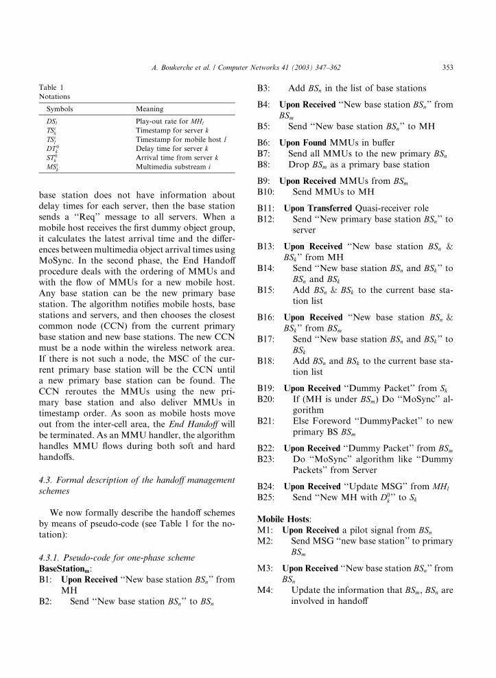
base station does not have information aboutdelay times for each server, then the base station
sends a ‘‘Req’’ message to all servers. When a
mobile host receives the first dummy object group,
it calculates the latest arrival time and the differ-
ences between multimedia object arrival times using
MoSync. In the second phase, the End Handoff
procedure deals with the ordering of MMUs and
with the flow of MMUs for a new mobile host.Any base station can be the new primary base
station. The algorithm notifies mobile hosts, base
stations and servers, and then chooses the closest
common node (CCN) from the current primary
base station and new base stations. The new CCN
must be a node within the wireless network area.
If there is not such a node, the MSC of the cur-
rent primary base station will be the CCN untila new primary base station can be found. The
CCN reroutes the MMUs using the new pri-
mary base station and also deliver MMUs in
timestamp order. As soon as mobile hosts move
out from the inter-cell area, the End Handoff will
be terminated. As an MMU handler, the algorithm
handles MMU flows during both soft and hard
handoffs.
4.3. Formal description of the handoff management
schemes
We now formally describe the handoff schemes
by means of pseudo-code (see Table 1 for the no-
tation):
4.3.1. Pseudo-code for one-phase scheme
BaseStationm:
B1: Upon Received ‘‘New base station BSn’’ from
MH
B2: Send ‘‘New base station BSn’’ to BSn
B3: Add BSn in the list of base stations
B4: Upon Received ‘‘New base station BSn’’ from
BSmB5: Send ‘‘New base station BSn’’ to MH
B6: Upon Found MMUs in buffer
B7: Send all MMUs to the new primary BSnB8: Drop BSm as a primary base station
B9: Upon Received MMUs from BSmB10: Send MMUs to MH
B11: Upon Transferred Quasi-receiver role
B12: Send ‘‘New primary base station BSn’’ toserver
B13: Upon Received ‘‘New base station BSn &BSk’’ from MH
B14: Send ‘‘New base station BSn and BSk’’ toBSn and BSk
B15: Add BSn & BSk to the current base sta-
tion list
B16: Upon Received ‘‘New base station BSn &BSk’’ from BSm
B17: Send ‘‘New base station BSn and BSk’’ to
BSkB18: Add BSn and BSk to the current base sta-
tion list
B19: Upon Received ‘‘Dummy Packet’’ from SkB20: If (MH is under BSm) Do ‘‘MoSync’’ al-
gorithm
B21: Else Foreword ‘‘DummyPacket’’ to new
primary BS BSm
B22: Upon Received ‘‘Dummy Packet’’ from BSmB23: Do ‘‘MoSync’’ algorithm like ‘‘Dummy
Packets’’ from Server
B24: Upon Received ‘‘Update MSG’’ from MHl
B25: Send ‘‘New MH with D0k ’’ to Sk
Mobile Hosts:
M1: Upon Received a pilot signal from BSnM2: Send MSG ‘‘new base station’’ to primary
BSm
M3: Upon Received ‘‘New base station BSn’’ from
BSnM4: Update the information that BSm, BSn are
involved in handoff
Table 1
Notations
Symbols Meaning
DSl Play-out rate for MHl
TSik Timestamp for server k
TSil Timestamp for mobile host l
DT 0k Delay time for server k
ST 0k Arrival time from server k
MSik Multimedia substream i
A. Boukerche et al. / Computer Networks 41 (2003) 347–362 353

4.3.2. Pseudo-code for two-phase scheme
Setup Handoff // Mobile host notifies current pri-
mary BS about the new assigned BS
Serverk: all the functions in MoSync Algorithm areshared here
Base Stationm:
B1: Upon Received a MSG ‘‘New BSn’’ from
MHl
B2: Add BSn to primary BS Candidate Set //
prepare to move
MobileHostl:
M1: Upon Received a pilot signal from BSnM2: Send MSG ‘‘New BSn’’ to Primary BSmM3: Send Request Dummy MMU to BSn //
setup new synchronization through BSnM4: if (Within a MSC control) Initialize agency
on CCN to both BSn and BSm
End Handoff
Serverk:
S1: Upon Received a MSG ‘‘New Primary BS’’
from BSnS2: Change routing path of MMUs for MHl
S3: Send a MSG ‘‘New Primary BS’’ to BSm //
reply message
BaseStationm: // MSC chooses New Primary BS
B0: Upon Received a MSG ‘‘New Primary BS’’
from MSC
B1: Send a MSG ‘‘New Primary BS’’ to MHl,
and ServerkB2: ‘‘New PBS_Server’’ is set to ‘‘True’’ // Ser-
ver holds old pathB3: Send a MSG ‘‘New Primary BS, Request
MMUs’’ to BSnB4: Activate routing agency on CCN to re-
route MMUs
B10: Upon Received a MSG ‘‘New Primary BS,
Request MMUs’’ from BSnB11: Do Forward MMUs to BSn for MHl
B12: While (‘‘New PBS_Server’’)
B20: Upon Received a MSG ‘‘New Primary BS’’
from Serverk
B21: ‘‘New PBS_Server’’ is set ‘‘False’’ // we
know Server is changed
B22: Stop Forwarding MMUs to New Pri-
mary BS for MHl
B23: Deactivate the routing agency on CCN toreroute MMUs
B30: Upon Received a MSG ‘‘New Primary BS’’
from BSnB31: ‘‘PBS_All’’ is set ‘‘TRUE’’ // found a new
Primary BS for MHl
B32: If (MMUs on Buffer) then Forward MMUs
to MHl
B50: Upon Received MMUs from Serverk for a
new Primary BS
B51: If (‘‘PBS_All’’) Send MMU to MHl
through new Primary BSB52: Else Save MMUs on BSm // could not find a
new Primary BS
B60: Upon Received MMUs from BSn for MHl
B61: Send MMUs to MHl
MobileHostl:
M1: Upon Received a MSG ‘‘new Primary BSfrom the new BS’’
M2: Update Delay Information for BSm
5. Proof of correctness
The movement of mobile hosts can be divided
into four types: (i) no moving during the com-munication; (ii) moving from one cell into an inter-
cell area; (iii) moving from an inter-cell area to
another cell; and (iv) moving back to the original
cell shown in Fig. 5. There is no moving mobile
host in the case (i). Therefore, it is considered a
hard handoff, which our previous work has shown
to be correct [3]. Although the other cases are
similar to case (i), we still need to consider theproblem related to ‘‘this case happened before that
case’’. As we can see, we need only to consider
‘‘case (ii) happened before case (iii)’’.
Each mobile host MHl has a message buffer
of finite size b. Suppose that MHl has a constant
play-out rate of r multimedia units per second. If
354 A. Boukerche et al. / Computer Networks 41 (2003) 347–362

its servers are not able to keep the buffer suffi-
ciently full, then MHl will not be able to play-out
smoothly. Similarly, if the servers send multimedia
units too fast, the buffer will overflow. Suppose
that the buffer is partially filled. Let t be the point
in time at which the buffer will be empty if no moremultimedia units arrive; let T1 be the time by which
more multimedia units must arrive to guarantee
smooth play-out, given the bounded jitter; and let
T2 be the earliest time at which the buffer could
overflow, given the jitter. Suppose further that
there are K servers Sk sending multimedia streams
to MHl, that each stream has length I , and that dik
is the delay of the ith unit sent by Sk. Let dmaxk ¼
maxfdikj16 i6 Ig and dmin
k ¼ minfdikj16 i6 Ig. Let
ftmk be the time taken for forwarding an MMU
from one base station to another.
Theorem 1. Suppose that the servers Sk are servingthe single mobile host MHl that is moving from onecell to another cell and there is bounded jitter. Themobile host plays-out its multimedia units smoothlywithout buffer overflow whenever the servers Sk obeythe following two constraints:
ðaÞ tP T1 P 2dmaxk þ ftmk and ðbÞ t6 T2 þ 2dmin
k :
Proof. As explained earlier, only case (iii) must be
considered for the delay time dik because of for-
warding delay time ftmk . MHl plays-out its multi-
media units with constant rate r. The server Sksends multimedia units to MHl only as a result of
an initial ‘‘Request’’ message issued from BSm.
Consider the worst case delivery time. Assume that
MHl keeps moving from one cell to another cell.
Each delay time for each server is increased by the
delay time ftmk . If MHl requests MMUs and then
moves, there are two messages, a ‘‘Request’’ and a
‘‘Reply’’, taking 2dmaxk þ ftmk total time for delivery.
Therefore, t cannot be allowed to fall below this
figure, i.e., tP T1 P 2dmaxk þ ftmk . In the best case
where it takes 2dmink for both the ‘‘Request’’ and
‘‘Reply’’ messages to be sent, overflow may occur
if MHl does not play out its current units by the
time T2 plus the minimum time for the next unit to
arrive, i.e., t6 T2 þ 2dmink .
6. Simulation experiments
We have developed a discrete-event model to
simulate a cellular wireless multimedia system on a
combination of wireless and wired networks. We
have assumed that wired networks are used for
communication between base stations and multi-media servers, and that cellular wireless networks
are used for communicating between multimedia
mobile hosts and base stations. In our model, there
are 300 channels available for 60 cells, with system
load equally distributed over all cells. Each multi-
media host has buffer space at least three times as
large as the largest MMU delivered from any
server and at most six times as large.Experimental evaluation of our handoff man-
agement and synchronization schemes requires the
examination of several test cases, comprising many
types of jitter and resynchronization. We evaluate
the performance of MoSync and the two handoff
management schemes for both uniform and non-uniform MMU arrival distributions. Table 2 dis-
plays the simulation parameters we have used inour experiments.
Fig. 5. Location and movements of MH.
A. Boukerche et al. / Computer Networks 41 (2003) 347–362 355

In the uniform case, we evaluate the perfor-mance of our scheme assuming uniform MMU
delay under jitter. All cells have the same mul-
timedia unit demand, and the requests from the
mobile host have inter-arrival time k and mean
service time l. All of our schemes are simulated
over four uniform MMU delay ranges: (A) 0–20
ms, (B) 20–40 ms, (C) 40–60 ms, (D) 60–80 ms.
MMU delay times for all of the multimediarequests are evenly distributed between the mini-
mum and maximum delay times, with the mini-
mum delay time for delivery assumed to be 50 ms
in each case and with the delay time for routing
between base stations assumed to be 20 ms. As we
shall see, the different jitter ranges have different
effects. For example, jitter ranges A and B will
cause overflow after some point while range D willcause underflow.
In the second, non-uniform case, an exponential
distribution is assumed. For this model, we simu-
late the algorithm over three MMU delay ranges:
(A) 0–200 ms, (B) 0–400 ms, (C) 0–600 ms. The
ranges are exponentially distributed with mean
values of 20, 40 and 60 ms, respectively. We set an
upper bound for each non-uniform distribution toavoid failure caused by very large delays in deli-
very from MMUs to mobile hosts. The mean
communication session is set to 20 MMUs, and
mean buffer size of a mobile host is set to three
times the size of an MMU. These ranges will also
exhibit different behaviors, as we shall see later.
We evaluate the performance of our algorithms
using variable-sized buffer space for each mobile
host and a variable number of requests from the
mobile hosts. We also choose the following per-
formance metrics to evaluate our schemes:
ii(i) message complexity, which measures the
overhead of our scheme in terms of the num-ber of messages needed to satisfy the user�smultimedia request
i(ii) buffer usage, which measures the synchroni-
zation behavior for each mobile host
(iii) underflow, which measures the average defi-
ciency in the client�s buffer of the number
of MMUs currently needed for smooth
play-out(iv) overflow, which measures the average num-
ber of MMUs that overflow a mobile client�sbuffer.
6.1. Experimental results
In this section, we divide our set of simulation
experiments into two parts. In the first part, wesimulate the one-phase algorithm with MoSync. In
the second part, we implement the two-phase
scheme with MoSync. In both parts, we evaluate
both algorithms using the above metrics. The fol-
lowing experimental data was obtained by aver-
aging several runs.
6.1.1. Part A for the one-phase scheme
In this section, we implement a one-phase
scheme that controls buffer usage and reduces the
number of messages between source and quasi-
receiver. In both parts, we evaluate the one-phase
scheme using the above metrics. The results ob-
tained for buffer usage are shown in Figs. 6 and 7in both uniform and non-uniform cases during
handoff.
In Fig. 6, buffer usage for the ranges A1, A2 and
A3 is always greater than 0 and less than 18
MMUs, which means that all MMUs can continue
to play-out smoothly over the full range of 50 re-
quests. With range A4, underflow occurs before the
request is received. Note that the rate of claimedbuffer space is the number of frames divided by the
number of requests. For example, with range A4, a
mobile host needs buffer space for 38 MMUs on
Table 2
Simulation parameters
Number of cells 60
Number of servers 4
Buffer size of a MH Three times an MMU
Ployout time/MMU 100 ms
Mean service time lArrival rate kForward time to BS 20 ms
Rate of handoff 5% of MMUs
RTT to request/deliver
an MMU
50 ms
Jitter (uniform) A1[0–20], A2[20–40], A3[40–60],
A4[60–80] ms
Jitter (non-uniform) B1[0–200], B2[0–400], B3[0–600] ms
356 A. Boukerche et al. / Computer Networks 41 (2003) 347–362

average over the full 50 requests, as we shall see inPart B but in Part A, A4 needs buffer space for only
22 MMUs on the same requests. The claimed
MMUs are 42% less than in the case of Part B, as
we shall see later. In Fig. 7, buffer usage for the
range B1 is always greater than 0 and less than 5
MMUs, which means that all MMUs can continue
to play-out smoothly over the full range of 50 re-
quests. With ranges B2 and B3, underflow occursbefore the request is received. Note that the rate of
claimed buffer space is the number of frames di-
vided by the number of requests. Both Figs. 8 and
9 show that our scheme performs quite well in
all ranges of jitter, because the average number
of messages per MMU is bounded by 12. Inthe special case of ranges A1, A2 and B1, message
complexity is close to 11 after two MMU requests
in the uniform case. These results are worse than
those obtained in Part B, as we shall see later.
Both Figs. 10 and 11 show the results of our
schemes in both uniform and non-uniform cases of
underflow. In Fig. 10, only the data for range A4
produces underflow after 78 MMU requests. Also,almost 100% of new requests cannot receive en-
ough MMUs to play-out smoothly. The ranges A1,
and A2 do not produce any underflow until request
100 and range A3 cause a little overflow. As we
can see in Fig. 11, the data for ranges B2 and B3
Fig. 7. Buffer usage for one-phase algorithm: non-uniform.
Fig. 8. Message complexity for one-phase algorithm: uniform.
Fig. 9. Message complexity for one-phase algorithm: non-
uniform.
Fig. 6. Buffer usage for one-phase algorithm: uniform.
A. Boukerche et al. / Computer Networks 41 (2003) 347–362 357

produces underflow after 62 MMU requests.After 110 MMU requests, almost 100% of new
requests cannot receive enough MMUs to play-out
smoothly. The range B1 does not produce any
underflow until request 150. In Figs. 12 and 13, we
portray the overflow rate for both uniform and
non-uniform cases. Recall that the overflow rate
represents the average number of MMUs that
overflow a mobile client�s buffer, while the under-flow rate represents the average deficiency in the
client�s buffer of the number of multimedia units
currently needed for smooth play-out. As we can
see, our scheme exhibits a very low overflow and
underflow rate in all ranges of jitter and in both
uniform and non-uniform cases.
6.1.2. Part B for two-phase scheme
Figs. 14 and 15 portray the buffer usage of the
two-phase algorithm according to the number ofmultimedia requests. As we can see in Fig. 14,
ranges A1, A2 and A3 are always greater than 0 and
less than 20 which means that all MMUs can play-
out smoothly as long as they hold proper buffer
size. Range A4 requires about 38 MMUs more to
play-out smoothly at the same number of requests
at 15 requests. In Fig. 15, buffer usage for the
range B1 is always greater than 0 and less than 5MMUs, which means that all MMUs can continue
to play-out smoothly over the full range of 50 re-
quests. With ranges B2 and B3, underflow occurs
Fig. 12. Overflow rate for one-phase algorithm: uniform.
Fig. 13. Overflow rate for one-phase algorithm: non-uniform.
Fig. 10. Underflow rate for one-phase algorithm: uniform.
Fig. 11. Underflow rate for one-phase algorithm: non-uniform.
358 A. Boukerche et al. / Computer Networks 41 (2003) 347–362

before the request is received. Figs. 16 and 17
portray the message overhead of our algorithm for
the uniform. As we can see in Fig. 16, ranges A1
and A2 need a message complexity that is 8 after 2
requests while range A3 and range A4 need a mes-sage complexity of only 9 after 15 requests. Fig. 17
portrays the message overhead of our algorithm
for the non-uniform case. As we can see in Fig. 17,
range B1 needs a message complexity that is 8 after
2 requests while range B2 and range B3 need a
message complexity of only 9.5 after 2 requests. In
Figs. 18 and 19 we have a high rate of underflow
with range A4 in the uniform case while ranges A1,A2 and A3 do not produce underflow before 100
MMU requests. The ranges A2 and A3 show around10% underflow rate after 100 MMU requests. In
Fig. 19, our results indicate that the data in range
B1 do not cause underflow. In our simulations, the
rate of underflow for the ranges B2 and B3 reaches
100% at 62 requests. In Figs. 20 and 21, we portray
the overflow rate for the uniform and non-uniform
cases. As we can see, our scheme performs quite
well for all ranges of jitter.Based upon the results above, we can conclude
that the one-phase scheme in the case of reason-
ably bounded jitter supports inter-stream syn-
chronization with an acceptable delay. Note that
the one-phase scheme uses a delay time to allow
Fig. 15. Buffer usage for two-phase algorithm: non-uniform.
Fig. 16. Message complexity for two-phase algorithm: uniform.Fig. 14. Buffer usage for two-phase algorithm: uniform.
Fig. 17. Message complexity for two-phase algorithm: non-
uniform.
A. Boukerche et al. / Computer Networks 41 (2003) 347–362 359

intra-synchronization and thereby guarantees
inter-stream synchronization as well. Our results
indicate that the two-phase algorithm exhibits amuch better message complexity than the one-
phase scheme.
7. Conclusion and future research
Synchronization among mobile clients and
multimedia units has proven to be a very chal-lenging problem in a wireless environment when
compared to a wired one. In this paper, we have
presented MoSync, a distributed synchronization
mechanism for wireless multimedia systems. We
have proposed two handoff management schemes
to support MoSync and the synchronization of
multimedia units (MMU) for mobile clients in a
distributed and wireless multimedia system thatuses base stations as quasi-receivers to control the
MMUs synchronization. The proposed solutions
with MoSync cope with network jitter, end-systemjitter, clock drift, and changing network conditionsduring a soft handoff. Hence, our schemes are
suitable both for synchronizing inter- and intra-streams during playback video and also for re-synchronizing streams in a wireless network. Theschemes are proposed for managing MMUs and
delivering them to mobile hosts on time. We have
also presented a set of simulation experiments that
study the performance of our algorithms. We haveFig. 20. Overflow rate for two-phase algorithm: uniform.
Fig. 21. Overflow rate for two-phase algorithm: non-uniform.
Fig. 19. Underflow rate for two-phase algorithm: non-uniform.
Fig. 18. Underflow rate for two-phase algorithm: uniform.
360 A. Boukerche et al. / Computer Networks 41 (2003) 347–362

simulated the proposed schemes evaluating their
performance in several cases using different arrival
patterns. First, we have measured their message
complexity and buffer usage, then we have re-
ported our algorithm�s performance under varieties
of jitter in terms of the amount of underflow andoverflow at each mobile host.
As future work of this research, we plan to
enhance our synchronization protocols by includ-
ing the QoS provisioning and guarantees between
the end systems, and introduce analytical and
simulation models to investigate and obtain crucial
performance characteristics of our schemes. Next,
we intend to examine the potential importance ofpacket scheduling on the performance of MoSync.
Future work is needed to determine the impact of
poor and good packets scheduling on a wider
range of wireless multimedia applications [4,7].
Acknowledgements
Heartfelt thanks to Ioanis Nikolaidis, and
Harry Rudin, the Joint Editor-in-Chief of Com-
puter Networks, for reviewing the manuscript and
providing criticism. Thanks are in order to the
anonymous referees for their valuable comments
and suggestions that helped us improve the quality
of this paper.
References
[1] E. Biersack, W. Geyer, Synchronization delivery and play-
out of distributed stored multimedia streams, in: Multi-
media Systems, vol. 7, ACM/Springer, New York/Berlin,
1999, pp. 70–90.
[2] G. Blakowski, R. Steinmetz, A media synchronization
survey: reference model, specification, case studies, IEEE
Journal on Selected Areas in Communications 14 (1) (1996)
5–35.
[3] A. Boukerche, S. Hong, T. Jacob, A synchronization
scheme of multimedia streams in mobile systems: Proof
and correctness, Proc. 26th IEEE International Conference
on Local Networking, Tampa, FL, 2001, pp. 638–645.
[4] A. Boukerche, S. Hong, T. Jacob, Synchronization proto-
cols for wireless multimedia systems, Proc. IEEE Interna-
tional Workshop on Mobility Management and Wireless
Access. Fort Worth, TX, 2001, pp. 25–30.
[5] G.H. Forman, J. Zahorjan, The challenges of mobile
computing, IEEE Computer 27 (6) (1994).
[6] V.K. Garg, IS-95 CDMA and CDMA2000, Prentice Hall,
Englewood Cliffs, NJ, 1999.
[7] Y. Ishibashi, S. Tasaka, T. Takeo, A performance
comparison of media synchronization schemes for collab-
orative systems in an interconnected ATM-wireless LAN,
Proc., IEEE PIMRC�98, 1998, pp. 265–271.
[8] T.V. Johnson, A. Zhang, Dynamic play-out scheduling
algorithms for continuous multimedia streams, in: Multi-
media Systems, vol. 7, ACM/Springer, New York/Berlin,
1999, pp. 313–325.
[9] M. Kato, Y. Kawai, S. Tasaka, Performance evaluation of
media synchronization in PHS with the H.223 Annes
multiplexing protocol, Proc. IEEE ICUPC�98, 1998, pp.
183–190.
[10] M. Kato, S. Tasaka, K. Nakamura, A comparison of
media synchronization quality between TCP and UDP in
PHS Internet access, Proc. IEEE PIMRC99, 1999, pp.
1092–1097.
[11] L. Lamont, L. Li, R. Brimont, N.D. Georganas, Synchro-
nization of multimedia data for a multimedia news-on-
demand application, IEEE Journal of Selected Areas in
Communications 14 (1) (1996) 264–278.
[12] H. Okura, M. Kato, S. Tasaka, A media synchronization
experiment on continuous media transmission in Bluetooth
LAN access, Proc. IEEE PIMRC 2001.
[13] M.J. Perez-Luque, T.D.C. Little, A temporal reference
framework for multimedia synchronization, IEEE Journal
of Selected Areas in Communications 14 (1) (1996) 36–51.
[14] S. Tasaka, Y. Ishibashi, Stored media synchronization
schemes in ATM and wireless networks: A performance
comparison, Conf. Rec IEEE ICUPC�97, October 1997,
pp. 766–772.
[15] S. Tasaka, H. Nakanishi, Y. Ishibashi, Dynamic resolution
control and media synchronization of MPEG in wireless
LANs, Conf. Rec IEEE GLOBECOM�97, November 1997,
pp. 138–144.
[16] T. Znati, R. Simon, B. Field, A network-based scheme for
synchronization of multimedia streams, TR-95-02, Dept.
of Computer Science, Univ. of Pittsburgh, Pittsburgh, PA,
1995.
Azzedine Boukerche is an AssistantProfessor of Computer Sciences at theUniversity of North Texas, and Di-rector of the Parallel, Distributed andMobile Systems (PARADISE) Re-search Laboratory at UNT. Prior tothis, he was working as a Senior Sci-entist at the Simulation Sciences Divi-sion, Metron Corporation located inSan Diego. He was employed as aFaculty at the School of ComputerScience McGill University, and alsotaught at Polytechnic of Montreal. Hespent a year at the JPL-California In-
stitute of Technology where he contributed to a project centeredabout the specification and verification of the software used tocontrol interplanetary spacecraft operated by JPL/NASALaboratory.
His current research interests include multimedia system, wire-less networks and mobile computing, distributed computing,
A. Boukerche et al. / Computer Networks 41 (2003) 347–362 361

distributed interactive simulation, and VLSI designs. Dr.Boukerche has published several research papers in these areas.He was the recipient of the best research paper award atPADS�97, and the recipient of the 3rd National Award forTelecommunication Software 1999 for his work on a distributedsecurity systems on mobile phone operations, and has beennominated for the best paper award at the IEEE/ACMPADS�99 and ACM MSWiM2001. He was the Program Chairof the IEEE International workshop on Distributed Simulationand Real Time Applications (DS-RT�99), the Program Chair ofthe ACM Workshop on Modeling, Analysis and Simulation ofWireless and Mobile Systems (MSWiM�99), the General Co-Chair of the principle Symposium on Modeling Analysis, andSimulation of Computer and Telecommunication Systems(MASCOTS), in 1998, the General Co-Chair of the ACMworkshop on modeling Analysis, and Simulation of mobile andwireless Systems, (MSWiM 2000), and the General Chair of theIEEE International workshop on Distributed Simulation andReal Time Applications in 2000, a Guest Editor for VLSI Design,the Journal of Parallel and Distributed Computing (JPDC),ACM Wireless Networks (WINET), and ACM Mobile Networksand Applications (MONET). Boukerche serves as the ProgramCo-Chair of the 35th Annual Simulation Symposium, ProgramCo-Chair of 10th IEEE/ACM MASCOTS 2002, Program Co-Chair of IEEE MobiWAC 2002, Program Vice Chair ofWWW�02, and General Co-Chair of the Int�l InformationTechnology Symposium (I2TS�2002). He serves as a Vice pro-gram Co-Chair for EuroPar 2003. He has been a member of theProgram Committee of Globecom, ICPP, MASCOTS, ICC,ICCI, MSWiM, PADS, VTC and WoWMoM conferences. Dr.Boukerche is a member of IEEE and ACM, and is an AssociateEditor of TRANSACTIONS of the SCS.
Sungbum Hong received his BS inElectronics Engineering from Kook-mim University, Seoul, Korea, in 1985.He had worked at the Oriental Tele-communication Co., Sungnam, Korea,as a software engineer from 1984 to1987.
He received a MS degree in Com-puter Science from University of Ten-nessee, Chattanooga, TN., in 1993. Heis currently a Ph.D. candidate in theInterdisciplinary Program in Informa-tion Science at University of NorthTexas, Denton, TX. He have been in-
volved in research in wireless computing since 1997. His re-search interests are in system performance and evaluation ofparallel and distributed simulation systems and the design ofdistributed algorithms for wireless communication systems.
Tom Jacob received his Ph.D. inMathematics from Emory Universityin 1974. Currently Associate Professorof Computer Science at the Universityof North Texas, he has also been onthe faculty at the University of NewOrleans and the University of Dallas.His research interests are in distributedcomputing, networking and telecom-munications.
362 A. Boukerche et al. / Computer Networks 41 (2003) 347–362