Embed Size (px)
Citation preview
CHAPTER 5
SYNCHRONIZATION SCHEMES FOR MC CDMA SYSTEM
5.1 INTRODUCTION
Information about the communication channel. such as the channel phase
response, is necessary for the conshuction of various receivers. In many practical
situations, this information is not known apriori and the relevant channel parameters
have to be estimated from the received signal. The three maln channel parameters
required by most receivers are the camer frequency, the carrier phase, and the symbol
timing of the received signal. The camer frequency of the received signal may be
different from that of the nominal value of the transmitter carrier frequency. This
discrepancy can be the results of the deviation of the transmitter oscillator from the
nominal frequency and more importantly, the Doppler effect when the transmitter is
in motion relative to the receiver. In reality, it takes a finite amount of time for the
information-bearing electromagnetic wave to travel from the transmitter to the
receiver. This transmission delay introduces a mismatch between the symbol t~ming at
the transmitter and that at the receiver. The output of the matched filter is to be
sampled at an exact time to optimize the error performance. The symbol timlng at the
receiver is to be known (or equivalently, the transmission delay) in order to eliminate
the performance degradation due to the timing mismatch. The canier phase of the
received signal is the sum of three major components, namely, the random phase of
the transmitter oscillator, the channel phase response, and the phase due to the
transmission delay. In order to model all the three channel defects, a simple non-
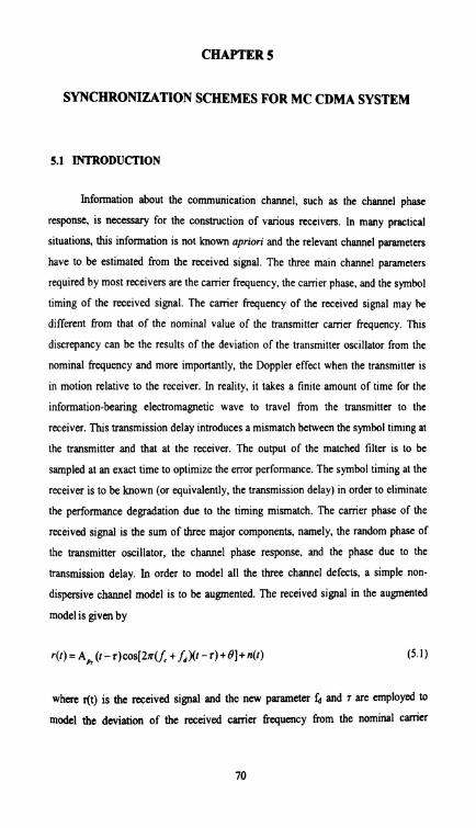
dispersive channel model is to be augmented. The received signal in the augmented
model is given by
where r(t) is the received signal and the new parameter fd and T are employed to
model the deviation of the received carrier frequency from the nominal camer

frequency and the transmission delay, respectively. Very often, the phase terms in
(5.1) are combined to a single phase term ( = 0- 2n(f, + f,)r modeling the received
carrier phase.
The process of estimating this parameter is called synchronization. The
process of estimating the carrier phase is known as carrier phase synchronization and
can be accomplished by a Phase Locked Loop (PLL) circuit. The process of
estimating the transmission delay is known as symbol timing synchronization, which
can be accomplished by a delay locked loop (DLL) circuit. It turns out that the same
PLL circuit used for carrier phase synchronization can also be employed to track the
canier frequency mismatch when it is significant.
Consider a BPSK system in which the received signal is given by
where n(t) is an AWGN process with noise spectral density N,J2. Using
synchronization process, the estimates of the parameters fd, T and gS are obtained.
Therefore, the correlator demodulator based on these estimated parameters as shown
in Figure 5.1 is formed.
Fig.S.1 Correlator receiver for BPSK with estimated parameters
It follows that when r -r < T , the average bit error probability (assuming the I r l bit values '0' and '1' are sent with equal probabilities) given by

where a = - E cos[2x( f, - j,)r +( ) - ; ) ]d l T ' "7':' mu(r.r)
It is noted that a5 l with equalityonly if f, = f,, r = r and #=/(mod 2x)
Hence, error in the estimation of any of the parameters will cause the error
probability to go higher than the optimal value Q,( - ). From the above result, it E- is found that if the data rate is much higher than the estimat~on error In fd. then
where A s = s -1 and A$= $ -$ . Therefore, errors in estimating both transmission
delay and the camer phase increases the bit error rate.
Receiver synchronization is a major problem in a mobile radio env~ronment
where the communication channel is subject to rapid changes. Communication In
spread spectrum systems is impossible unless the received spreading waveform and
receiver generated replica of the spreading waveform are initially synchronized in
both phase and frequency. Phase and frequency synchronization is usually
accomplished by performing a two dimensional search in the timelfrequmcy
ambiguity area. Generally, this process must be accomplished at very low SNR, as
quickly as possible, using the minimum amount of hardware [174]. There are four
levels of synchronization
Carrier Synchronization . Symbol Synchronization . Frame Synchronization
Network Synchronization

In case of coherent phase modulation, the receiver is assumed to be able to
generate a set of reference signals whose phases are identical (expect perhaps for a
constant offset) to the phases of the signalling alphabet in use at the transmitter. These
reference signals are compared with the incoming signals in the pmess of making
maximum likelihood symbol decisions. In order to be able to generate these reference
signals, the receiver has to be in synchronization with the received carrier as shown in
the Figure 5.2. This means that there has to be phase concurrence between the
incoming carrier sinusoid and a replica of it in the receiver. In other words. if there
were no information modulated, the incoming sinusoid and the replica In the recelver
would pass through zero simultaneously. This IS what is known as being in phase lock
and is a condition that must be closely approximated ~f coherently modulated signals
are going to be accurately demodulated at the receiver.
5.1.2 Symbol Synchronization
All digital receivers need to have demodulators synchronized to the incoming
digital symbol transitions in order to achieve optimum demodulation as shown in the
Figure 5.3. The symbol synchronization can be classified into two basic groups. The
first group consists of the open-loop synchronizers, where circuits recover a replica of
the transmitter data clock output directly from operations on the incoming data
stream. The second group comprises the closed loop synchronizers. where closed-loop
data synchronizers attempt to lock a local data clock to the incoming signal by use of
comparative measurements on the local and incoming signals. Closed-loop methods
tend to be more accurate, but are much more costly and complex.
5.1.3 Frame Synchronization
For a receiver to make sense of the incoming data stream, the receiver needs to
be synchronized with the data stream's frame structure. Frame synchronization is
usually accomplished with the aid of some special signalling procedures from the
w t t e r . This procedure may be very simple, or fairly involved, depending on the
environment in which the system is required to operate.

Out of Synchronization Out of Synchronization Synchronized
Fig. 5.2 Carrier synchronization
Error Detection Error Detection Correct Detection
Fig. 5.3 Symbol synchroniution
74

nk bits Nd bits nr bits Nd bits nr bits
Data Stream
n* bits N~ bits nir bits Nd bits nk bits
Receiver generated frame marker replica
Fig.5.4 Frame synchronization
The simplest frame synchronization aid is the frame marker, illustrated In the
Figure 5.4. The frame marker is a single bit, or a short pattem of bits that thc
transmitter injects periodically into the data stream. The receiver must know the
pattem and the injection interval. The receiver, having achieved data synchronization,
correlates the known pattern with the incoming data stream at the known injection
interval. If the receiver is not in synchronization with the framing pattern, the
accumulated correlation will be low. Hence the receiver comes into frame
sqnchronization; however, the correlation should be nearly perfect, blemished only by
an occasional detection error.
The advantage of the frame marker is its simplicity. Even a single bit can
suffice as a frame marker if a sufficient number of correlations are accumulated
before deciding whether or not the system has achieved synchronization. The major
drawback is that the sufficient number may be very large, and thus the expected time
required to acquire synchronization would be long. Therefore, frame markers are most
useful in systems that transmit data continuously, and would be inappropriate for
systems that transmit in isolated bursts or systems that require rapid frame acquisition.
For systems with inconsistent or burst transmission or systems with rapid quisition
'eguirements [143], a synchronization codeword would typically be sent as pM of a

message header. The rtceiver must know the codeword and be constantly searching
for it in the data stream. Detection of the codeword would indicate a known position
in the data kame. The advantage of this system is that frame acquisition can be
essentially immediate. The only delay would be that required to process the incoming
codeword. The disadvantage is that the codeword must be relatively long, relative to
the frame marker, to keep the probability of false detection low. The complexity of
the correlation operation is proportional to the length of the sequence, so the
correlator must be relatively complicated.
5.1.4 Network Synchronization
For systems using coherent modulation techniques, one-direction
communication such as broadcast channels, or single link communication, such as
most microwave links, land link, or fibre optic links, the synchronization architecture
that makes the most sense is to make the synchronization totally a receiver function.
For communications systems using non-coherent modulation techniques, or that
involve many user accessing a central communication node, such as satellite
communication systems, it often makes sense for synchronization to be mostly or
entirely a terminal function. This means that the terminal transmitter parameters are
modified to achieve synchronization, rather than modify the central nodes receiver
parameters. This must be the approach if the system uses TDMA. In TDMA each user
is allocated a segment of time to transmit information. The terminal transmitter must
he synchronized with the system in order for its transmitted burst of data to arrive at
the central node at the time when the node is prepared to receive the data.
Synchronization of the terminal transmitter also makes sense with systems that
combine signal processing at the central node with FDMA. If the terminals precorrect
their transmission to be synchronized with the central node, the node can use a fixed
set of channel filters and a single timing reference for the processing of all channels.
Otherwise, the node would require a separate time and frequency acquisition and
tracking capability for each incoming channel, and would need to deal with the
possibility of varying amounts of adjacent channel interference. It is quite obvious
that transmitter synchronization is often the better and more reasonable system
Vproach to synchronize a network. For CDMA based systems carrier and s)?nbol
Spchronization is important.

In the first part of this chapter, a novel method to estimate the frequency offset
for the desired user is proposed to be used in conjunction with the MU1 reduction and
suppression techniques discussed in chapters 2 to 4. In the second part of this chapter
a Non data aided frame synchronization i.e OFDM symbol synchronization algorithm
is proposed.
5.2 FREQUENCY SYNCHRONIZATION SCHEME FOR MC CDMA
SYSTEM
Multicanier transmission and, notably. MC CDMA system, is known to
provide remarkable resilience to multipath fading and impulsive noise. In order to
operate correctly, an MC CDMA receiver calls for accurate compensation of the
camer frequency offset in the input signal. In MC CDMA system, available
bandwidth is decomposed in to a set of disjoint equal bandwidth frequency. Since the
bandwidth of each sub band is less than the coherence bandwidth of the channel, MC
CDMA systems are more robust to the distortion induced by time-disperse channels
than DS CDMA systems. At the front-end of the receiver MC CDMA signals are
subject to synchronization errors due to oscillator impairments and sample clock
d~fferences. The demodulation of the received radio signal to baseband, possibly via
an intermediate frequency, involves oscillators whose frequencies may not be
perfectly aligned with the transmitter frequencies. This results in a carrier frequency
offset.
The most important effect of a frequency offset between a transmitter and a
receiver is the loss of orthogonality between the subcaniers resulting in inter canier
interference (ICI). The characteristics of this ICI are similar to white Gaussian noise
and lead to a degradation of the SNR. For both AWGN and fading channels, this
degradation increases with the square of the number of subcarriers. Like frequency
offsets, phase noise and sample clock offsets cause ICI and thus result in a
degradation of the SNR. In DS CDMA systems, many detection schemes are
proposed to eliminate the MUI. However if these schemes are used for MC CDMA
Systems, their performance deteriorates even in the presence of a small frequency
offset Therefore, the frequency offset and the MU1 should be jointly wnsidered.
Many schemes are proposed to estimate the frequency offget through the use of PLL,
frequency offset estimation and guard interval based hquency offset estimation
algorithms.
5.2.1 PLL Algorithm
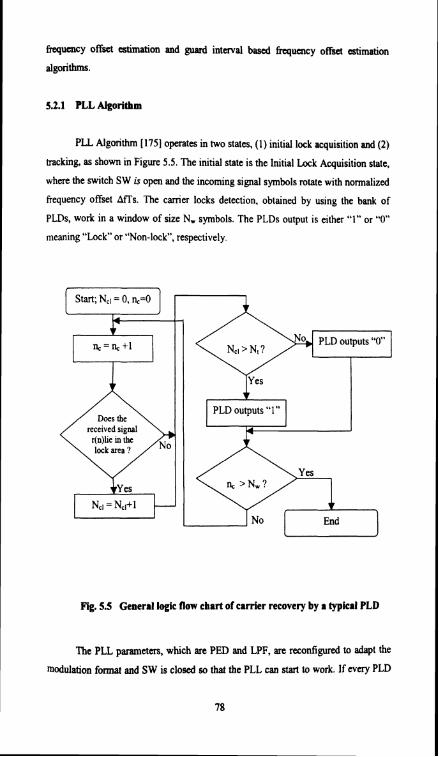
PLL Algorithm [I751 operates in two states, ( I ) initial lock acquisition and (2)
tracking, as shown in Figure 5.5. The initial state is the Initial Lock Acquisition state,
where the switch SW is open and the incoming signal symbols rotate with normalized
frequency offset AtTs. The carrier locks detection, obtained by using the bank of
PLDs, work in a window of size N, symbols. The PLDs output is either "I" or "0"
meaning "Lock" or "Non-lock, respectively.
N,, = N,,t I End 1
Rg. 5.5 General logic flow chart of carrier recovery by a typical PLD
The PLL parameters, which are PED and LPF, are reconfigured to adapt the
modulation format and SW is closed so that the PLL can start to work. If every PLD

outputs "O'', the state does not change, and the bank of PLD's work for initial
acquisition in the next window. If lock is lost in tracking state the state is changed
back to the initial lock acquisition state and SW is open. The acquisition time depends
on two parameters: the frequency offset and the phase difference between the adjacent
lock areas. The value of frequency offset and phase difference between the adjacent
lock area affect the rotation speed of the received signals and the maximum h m the
received signal position to the lock area, respectively and the signal is lost. This
increases the acquisition time and hence it is difficult to achieve synchronization.
5.2.2 Frequency Offset Estimation Algorithm
The estimation of frequency offset is addressed in a number of contributions in
this method. As a key part of the synchronization scheme, an estimator is proposed
based on the concept that works without the aid of pilot symbols and is independent
of the modulation of the carriers. In this method statistical redundancy in the received
signal, introduced by the cyclic prefix, provides the information about the offset. A
single OFDM symbol received by the base station is considered. It is assumed that the
N subcarriers constituting this symbol are subdivided in M bands of subcarriers, the
indices of which are collected in the set Mm. One transmitted OFDM symbol in the
mth band of subcaniers is
where NT is the duration of the OFDM symbol without the cyclic prefix and T, is the
length of the cyclic prefix. The model focuses on the frequency sub band division
property of the multiple-access scheme as this significantly affects the offset
estimation. The receiver offset estimator addresses the time-division property of the
target system by applying one estimator to every time slot. Perfect separation of the
users typically is accomplished by the removal of the cyclic prefix and the
demodulation by the FFT. Such separation, however, removes the redundancy which
is needed by the offset estimation in the synchronization scheme.

The MC CDMA signal as shown in the Figure 5.6 which is received by the
base station, is assumed to have N subcarrim and are subdivided in M bands of
subcarrim, the indices of which are collected in the set Mm. It associates with the mh
transmitted signal a time offset relative to the receiver symbol clock and a frequency
offset relative to the receiver demodulation frequency. In this system the requirement
of a maximum frequency offset of 1-2% of the intercarrier spacing becomes about
50 Hz. Each symbol is cyclically extended by 48 sec (205 samples), such that the total
symbol length becomes 288 sec. The length of the cyclic prefix is suficiently long to
provide immunity against channel dispersion. The system will perform better only if
the channel impulse response does not exceed the cyclic prefix duration.
Corrshtion Averaging
Fig. 5.6 Frequency offset estimation
5.2.3 Guard Interval Based Frequency Olfset Estimation
This section explains a new algorithm for the carrier frequency offset
estimation in an MC CDMA receiver. The samples n (-Ng S n SN,T -1) of the
received baseband signal r(t) belonging to the ifi block are shown in Figure 5.7. The
first Ng samples of the block (-Ng Sn S-1) belongs to the guard interval, while the
other NBT samples (0 9 -1) represent the useful block. This algorithm uses the
redundancy introduced by the guard interval.

Fig.S.7 Guard interval based frequency offset estimation
When the frequency error Af is null, rNs7 .,r*., is a real number. However, in
the presence of a frequency error the two samples r ~ N ~ T ., and r*., are affected by a
different rotation and the imaginary part of their product contains some information
about the frequency offset. The basic idea is to use this information for frequency
offset correction. The error signal €(I) corresponding to the lth block is given by
€(I)= (llL) C I r n [ r ~ ~ ~ ., r*.,] with 1 a SNg
The main disadvantage of this method is that noise due to multipath Rayleigh fading
channel cannot be eliminated very effectively since the subcaniers will be affected by
the AWGN noise also.
These schemes are good for OFDM but are quite troublesome with MC
CDMA due to the MU1 and the full correlation between the different subcaniers.
A novel method is proposed here for frequency synchronization in MC CDMA
system.

5.2.4 Proposed Virtual Subcarrier Based Synchronhtlon Algorithm
This method capitalizes on the fact that the system is not fully loaded, i.e., not
all available subcarriers are used for transmitting symbols. The proposed method
exploits these null, or virtual, subcaniers to enforce time and f q u e n c y
synchronization conversely, the method herein, guarantees unambiguous carrier offset
estimates with performance independent of the channel zeros location. Moreover, it is
specifically devised for multi user systems and is simpler to implement than the
algorithms explained earlier because it does not require any eigen-decomposition of
the received signals. Even though the presence of virtual subcarriers can be seen as
the transmission of known (null) symbols, there is a basic practical difference as the
transmission of null symbols does not imply any waste of power. Furthermore, null
sub carriers are intrinsically present in any non fully loaded MC system (a situation
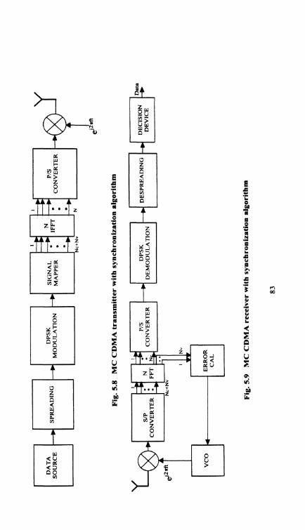
which occurs most of the time). Figures 5.8 and 5.9 depict a typical MC CDMA
transmission and reception system with proposed synchronization algorithm. To
verify the algorithm steps given in Figures 5.8 and 5.9 is followed and channel
simulation is similar to the one described in section 2.4.
The novelty lies in the algorithm for estimating and compensating both time
and frequency offsets. The basic idea for synchronization is fairly simple. The average
energy falling across the virtual subcarriers is measured and the oscillator frequency is
updated until a minimum of the measured energy is reached. In case of perfect
synchronization and no noise situation, null energy is observed. When some energy is
detected, the receiver oscillator is updated in order to minimize such energy.
Correspondingly, the synchronization algorithm is rather simple. An iterative search is
run which yields the frequency offset that minimizes the energy falling in the band
corresponding to the virtual subcarriers. Perfect synchronization leads to zero
MWISI (inter symbol interference) among MC CDMA symbols and null energy in
the band not occupied by information symbols. Conversely, non perfect
synchronization is revealed by the presence of MUIDS1 and of a non null energy in
correspondence with the null subcarriers.

5.25 Performme of V i a l Subcarrier Algorithm
MC CDMA system is simulated with 16/32/64 Recessing gains and
subcarriers, 214 virtual subcarriers and the channel is assumed to be Rayleigh fading
in AWGN environment. Rgure 5.10 shows the comparison of BER plot for the
MC CDMA system with and without ~j'nchr~nization for 16 subcarriers/processing
gain out of which 4 are virtual subcarriers. Simulation is performed for SNR from 0
dB to 10 dB in steps of 1 dB and the result implies that the system performs better
with synchronization. Figures 5.1 1 and 5.12 depict BER plots for MC CDMA system
for 32 and 64 subcaniers/processing gain respectively with 4 virtual carriers. Figure
5.13 compares the performance of a synchronized system using the proposed
algorithm with 32 SCPG for 214 VC. Figure 5.13 brings out that for the same
processing gain the performance of the system with 4 virtual carriers is better than the
2 virtual carriers. This is due to the fact that average error from the 4 VC can be used
effectively for frequency correction than from 2 VC. Figure 5.14 highlights the
performance comparison of the system with 64/16 PG for 4 VC, which indicates that
the performance is better for higher processing gain.
Fig.5.10 System performance for 16 SU16 PG and 4 VC
84
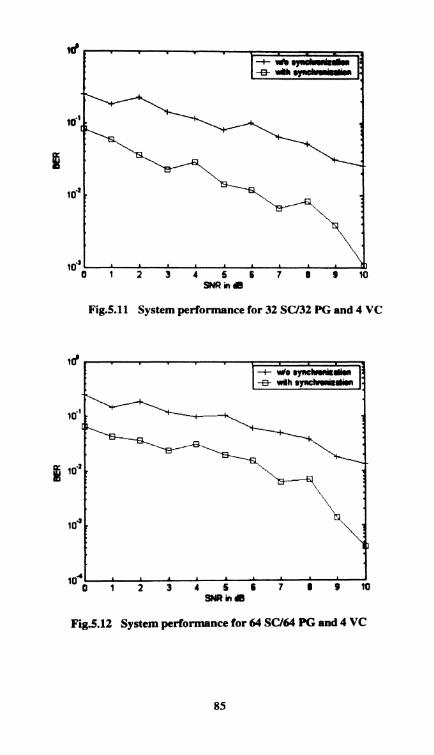
Fig.S.ll System performance for 32 SU32 PG and 4 VC
ld
16'
ig 10."
10'
SNR in dB
Fig.5.12 System performance for 64 SU64 PG and 4 VC
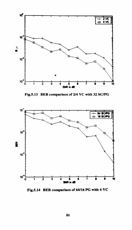
Fig.5.13 BER comparison of 2 4 VC with 32 SC/PG
10.' :
Bk
SNR in a
Fig.5.14 BER comparison of 64/16 PG with 4 VC

5.3 W E SYNCHRONIZATION FOR MC CDMA SYSTEM
Many systems used in digital communication smd data in synchronous back-
to-back frames. Whm a receiver tunes to such a data stream, it has no knowledge of
the frame boundaries. Frame synchronization is required to ensure that the receiver
reliably interprets the received bit stream on correct boundaries. Frame
synchronization is usually accomplished with the aid of some special signalling
procedure from the transmitter. The data aided technique and the non-data aided
technique are the two types of frame synchronization.
5.3.1 Data Aided Algorithm
In data aided technique some non information bits are stuffed at regular
intervals for frame synchronization purpose. The major drawback in this technique is
that the frame marker size may be very large in order to avoid false detection and the
expected time required to acquire synchronization would be long and also
transmission overhead is present. In the case of non data aided technique, the data
which is to be transmitted will be encoded in such a way that, encoded data itself can
be used for frame synchronization. In the case of CDMA systems, reception is not
possible unless the received spreaded waveform and receiver generated replica of the
spreading waveform are synchronized in both phase and frequency. Generally, this
process must be accomplished at a very low SNR, as quickly as possible, using the
minimum amount of hardware. As the data aided scheme incorporates transmission
overhead, it decreases channel capacity and bandwidth efficiency.
5.3.2 Non Data Aided Algorithm
To overcome this problem, nondata aided technique is being practiced,
wherein the information bit itself is used for frame synchronization. The advantage of
this technique is that it does not require any transmission overhead, it increases
channel capacity and bandwidth efficiency. The proposed frame synchronization
algorithm uses the non data aided technique and also supports variable 6ame size for
all users. The existing non data aided frame synchronization method for a single user
multi carrier system is described below. The basic idea behind this technique is, the

deletion of a subchannel is used to indicate the start of the frame. The subchannel to
be deleted is determined by the encoding block and the information of the deleted
subchannel is also retrieved by the algorithm used. For example consider 32 symbols
are there in a block of a frame. If the first symbol is 3, data in the third position is
placed in fust position and the third symbol is made zero. Therefore both the
information in first and third position is available and in the mean time inserted zeros
ensure frame synchronization. Let x be G random data symbol vector, i.e.
x= {XI x2 . . . XGI and D = { 1, Z... U), where denotes the transpose and D is the
data alphabet of size U. Each data symbol is mapped to a signalling symbol, y,, using
the MAP operation. The mapping is such that each possible data symbol is associated
with one particular value of a set of U distinct values y = [y I y 2. . y G] T, yn= A(x , ), A = (A(1) , A(2), ..., A(U) j, yn E A where n E [],GI, A is the signalling alphabet
with size U. Each y, is allocated a subchannel. The vector y is encoded by the Frame
encoding block only if it is the first symbol of a frame; otherwise, Z = y. Then, Z is
modulated to produce a symbol vector S. The Rayleigh fading channel is described by
a diagonal matrix C(a), with the fading coefficients on the main diagonal. Also the
additive white Gaussian noise, q(t), is combined with the signal. Thus, received signal
is r = C (a) x S + ~ ( t ) . The receiver consists of a demodulation block, DEMOD,
followed by frame detection and decoding block, FDDE, a signalling symbol decision
block, SSD, and a signalling symbol demapper, DMAP [I 761. In the receiver, perfect
OFDM symbol, carrier recovery and perfect channel estimation are assumed. A linear
equalizer is used to offset the effect of fading in the DEMOD. The frame encoder only
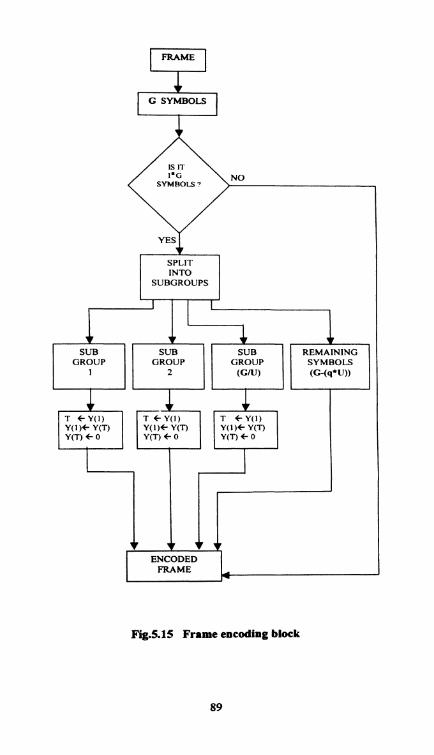
encodes the first symbol of every frame. The total number of subchannels, G, in
vector y is divided into q groups of U sub channels for frame encoding
y=[ y(l) y(2) y(3) ...y(q ) y, lT where y(n) is a IxU vector and y, is a vector of
size (G - qU) containing the remaining signalling symbols. Here, q is defined as the
maximum group available for frame encoding and is given by the integer part of the
division of G by U. Note that G > U is required here. The vector y~ is not involved in
the frame encoding process. Each vector y(n) in y is encoded as follows:
21 C y,l,Z ,I f O,& t y,, where p E [2,U], n # xl. The xl and 21 correspond to the
first data symbol and the signalling symbol in the first subchannel in each vector y(n)
respectively. The first data symbol, xl, specifies the i' subchannel which will replace
the first subchannel, Z I
FRAME
G SYMBOLS
NO
SPLIT
SUBGROUPS
ENCODED FRAME
I
I I
I
1
Fig.5.15 Frame encoding block
SUB GROUP
1
SUB GROUP
( G N )
SUB GROUP
2
REMAINING SYMBOLS (G-(q*U))
1 1 P
T C Y ( 1 ) Y ( l ) + Y( 'n Y(T) l 0
T C Y(1) Y ( l ) + Y(T) Y(T) C 0
7
- T C Y(I) Y ( l ) C Y(T Y(T) l 0

The flow chart describing this is given in Figure 5.15.Then. the i"' subchannel
is deleted and no signal energy will be transmitted in i' subchannel. It should be
noted that no information is lost in this process because the information in i*
subchannel is transmitted via the first subchannel, and the information in the first
subchannel is specified by the position of the deleted subchannel. The frame detection
and decoding block must first detect the start of the frame before it can recover the
data from a frame encoded symbol. Like the frame encoder, the received symbol is
divided into q groups of U subchannels: V= [ v(l) v(2) v(3). . .. . ... v(q ) v, lT where v(n) is l x U vector of the received signalling symbols, v(n) and v(r) is a vector
of size (G - qU) containing the remaining received signalling symbols. Again, the
vector v(r) is not involved in the frame detection or frame decoding processes. In each
v(n)vector, a subchannel that has the minimum absolute magnitude among the
subchannels within the group is selected. Then. the selected minimum absolute
1 mapitudo subchannels from all the groups are summed, i.e E = - imin(uh(u(n)))
4 I
where min(.) is the minimum of a group of number n and n E [I,q] and abs(.) is the
absolute value of the argument. E is then compared with a predefined threshold. This
threshold can be chosen according to the required false alarm and miss detection rates,
and considering the prevailing channel conditions: E > T F , HA and E < T F, HF where
TF is the threshold for frame detection, HF and HA are the hypothesis indicating the
frame is present or absent respectively. If all the elements in signalling alphabet set A
have similar energy and the consequences of a false alarm and a miss detection are the
same, then the threshold should be chosen as half the maximum absolute magnitude.
After the frame is detected, the subchannels in the frame encoded symbol have to be
rearranged to recover the actual symbol. This is simply the reverse of the frame
encoding procedure. For each v(n) vector, the position of the minimum absolute
magnitude subchannel among the subchannels within the group is determined by
i = pos (min (abs(v(n) ) ) ) where n E [I,q], and pos(.) is the position of the argument
in a vector. Then, the signalling symbol in i" subchannel is replaced by the signalling
vmbol in the first subchannel, and the signalling symbol for the first subchannel is
the ih element in signalling alphabet set, Z, f V 1 , Z l f A(i), Z,, f Vn where
n E [2,U], n #I. This frame decoding procedure is implemented only when a frame is
detected, otherwise, Z=V.

The existing method shows that the h e information can be embedded in the
normal data stream without the need for a special preamble sequence. Consequently,
h e synchronization can be achieved without transmission overheads. Furthermore,
the method has low complexity and is simple to implement. The major drnwbacks of
this algorithm are that FER offered is not satisfactory and it does not support multiple
services which is required for future generation services.
5.3.3 Proposed Modified Algorithm
In the modified algorithm, the main objective is to reduce the frame error rate.
This is accomplished by incorporating the barker sequence in the existing algorithm.
The existing algorithm encodes only the fint G symbols and transmits the remaining
data bits of a particular frame which is of a fixed size as such. Wherein here the data
bits are frame encoded as in the existing algorithm to indicate the start of the frame
with a modification. Here instead of zeros, a five bit barker sequence, say 11 101 is
used as a marker. For a bit value of 1, the algorithm is applied for G symbols. For a
bit value of 0, the G symbols are transmitted as such. The frame error rate for the
proposed algorithm is seen to be less when compared to the existing one.
As the existing algorithm provides only a fixed frame size for a particular user,
it is not possible to support integrated services. In the existing frame synchronization
scheme, if the frame synchronization technique is applied to all q groups of U sub-
channels, then the frame size is constrained to be any multiple of G symbols.
However, if it is applied to the upper half of the q groups and to the lower half of the
q groups independently, then the frame size can be any multiple of O.SG. If the upper
half and lower half are fbther split into two subgroups, the frame size can be any
multiple of 0.25G. Nevertheless, this can be done only if the division of G by the
number of subgroups, ns, yields an integer. It should be noted that, as ns increases, the
number of sub-channels that can be used for frame detection in each subgroup, Glns,
decreases. Hence, the flexibility in frame size is inversely dependent on the robustness
of the frame synchronization. The minimum possible frame size, U, is achieved when
ns = q, where U is the signalling symbol alphabet size. Thus the existing algorithm
ensures different frame size for different user. But if each user is assigned a fixed
frame size, one cannot implement integrated service facility. By varying the size of

the frame for each user, integrated senices can be incorporated. If the frame size is
made variable in the existing algorithm the probability of miss (p3 and false alarm
@I) is large resulting in increased h e e m r rate. But in the proposed algorithm with
the help of the barker sequence the data bits are frame encoded as in the existing
algorithm to indicate the start as well as the end of the frame. The e n c d n g is carried
at the start and end of the frame and the intermediate symbols are transmitted as such.
At the receiver side, the probability of a 0 in the marker sequence becoming a 1 is
very less. This property of the algorithm decreases the probability of false detection
and facilitates variable frame sizes at reduced FER.
5.3.4 Performance Comparison for Single Service and Multi Service System
With the MC CDMA system setup, the frame synchronization block is
included to implement the data aided technique. The source alphabets D are randomly
generated which takes a value up to U, say U = 7. In this trial 2000 symbols are
generated. The generated symbols are converted to bits and the frame marker 1s
inserted at the start of each frame. The marker sequence used here is a 15 bit code,
Marker = [ 1 1 1 1 0 1 0 1 1 0 0 1 0 0 01. The resultant bits are spreaded and is
modulated using BPSK. The modulated signal is transmitted through the Rayleigh
fading channel and the performance of the system is analyzed. At the receiver side,
coherent detection is carried out and the bits are retrieved. For various signal to noise
ratios (SNR), the bit error rate (BER) is calculated. Figure 5.1 6 explains the simulated
plot between BER and SNR in Rayleigh channel for a MC CDMA system
incorporating data aided algorithm. In non data aided technique, the source alphabets
x are generated randomly which takes a value from D. x = [XI, XI, x3 .... x,] and
D = [I , 2, 3, U] where x, E D. Here U = 7 and n = 2000. The generated symbols are
mapped using a matrix, map = [7 6 5 4 3 2 11, that is in the reverse order. The frame
size (F) is fixed to be of a particular value (say 100 symbols). A number G (say 25)
which is a factor of F is chosen and the first G symbols in each frame are considered
for the frame e n d i g and the remaining symbols are transmitted as such. The G
symbols are divided into q groups each having U symbols, where q is mod ( G U . The
first symbol in each group is taken and demapped and the position of the s p b o l to be
encoded is given by this value. The symbol at that position is moved to the first

psition of the group and the symbol at that position indicated by demappad value is
deleted (made as zero). Hence the position of the deleted symbol gives the actual first
symbol in the group and the first symbol present in the group gives the actual symbol
at the deleted position. Hence no data is lost in frame encoding and no additional bits
are required for frame synchronization. This is followed for every frame and it is
transmitted through MC CDMA system similar to the data aided technique as
explained above.
Figure 5.17 shows the simulated plot between BER and SNR in Rayleigh
fading channel for a MC CDMA system incorporating non data aided algorithm. At
the frame detection block, the fiames are scanned for the G symbols that are frame
encoded. If it identifies that G symbols, then it is indicated as the start of the frame
and a stream of G symbols are added to it, to have a complete frame (100-25 = 75
symbols). Again the receiver scans for the next starting point of the frame. If the
frame start is not identified the frames are left as such. Figure 5.18 compares the BER
for non data aided and data aided techniques in Rayleigh fading channel in a
MC CDMA system. From this figure it is clear that there is not much of a difference
in bit error rate for non data aided and data aided techniques. This is due to the fact
that whatever be the frame synchronization algorithm used the bit error rate depends
only on the channel and the type of modulation used. Further the BER depends on the
multiple access technique used and the system provides a minimum BER due to the
multi canier code division multiple access technique used. Hence the difference is
produced only in the frame error rate of the systems. To analyse the performance of
modified algorithm, a barker sequence of length 'mb' is chosen, which satisfies the
correlation property. The first mb x G symbols in the frame is considered for frame
encoding, where mb is the length of the barker sequence. The barker sequence is
assumed as 11 101 and mb = 5 and G = 25. Hence first 125 symbols are taken and are
kame encoded with respect to the barker sequence. The digit '1' in the barker
sequence indicates that the G symbols are frame encoded as explained above. The
digit '0' indicates that the G symbols have to be transmitted without frame encoding.
Thus the first 125 symbols arc frame encoded based on barker sequence.

Fig.5.16 Performance of data aided algorithm
10.'
P to"
: \\ \
\ !
'0'1 1 s t i i 2 i i 3 b ; SLIR in dB
Fig.5.17 Performance of non data aided algorithm

Fig.5.18 Comparison of non data aided and data aided schemes
Table 5.1 and Figure 5.19 show the comparison of FER in Rayleigh fading
channel for modified algorithm, the existing non data aided and data aided technique
for fixed frame size. The FER of the modified algorithm is very less when compared
to the existing technique for a fixed frame size. This is due to the correlation property
of the barker sequence which provides a reduced probability of false alarm and
probability of miss. In order to make the frame size a variable one and to reduce the
frame error rate further, the frame marker encoding is canied out both at the start and
end of the frame. i s , the last 125 symbols are frame encoded with the same barker
sequence as explained earlier. The comparison of the frame error rate for the different
dgorithms for variable frame sizes are shown in Table 5.2 and Figure 5.20 (S,- start
only encoded, S&& start and end encoded) and it reveals that the modified frame
synchronization algorithm with the frame marker encoding at the start and end of the
frame provides a better FER than any other scheme.

Table 5.1 CompPrison of the existing and d i e d algorithm for Rxtd frame size
- --
Fig. 5.19 FER Comparison of algorithms for fixed frame size
Table 5.2 Comparison of existing and modified algorithm for variable frame size

Fig.5.20 FER Comparison of algorithms (variable frame size)
5.4 CONCLUSION
In future wireless communication system, the main aim is to integrate all the
multimedia services (voice, data and video services) in to a single unit. Hence systems
which incorporate high data rate services are required to provide to the users with all
the facilities. The channel capacity of the system should be improved in order to
accommodate more number of users. Canier synchronization algorithm for MC-
CDMA systems has been proposed which tackles a very important issue in MC-
CDMA transmission in Rayleigh and Rician channels. In this investigation the
simulated results of BER without and with canier frequency synchronization are
being compared, and it is proved that the BER reduces when the synchronization
algorithm is incorporated, which in turn increases the capacity.
The modified frame synchronization algorithm presented in the second pM of
this chapter exploits the advantage of the Barker sequence and it can be seen that FER

reduces to a greater extent. This algorithm provides an added advantage to the Barker
sequence because of the property that the probability of the bit 0 of the frame marker
becoming a 1 is very less. This is due to the fact that at least one of the symbols in all
the q groups should be deleted in order to make a 0 as 1. Thus the probability of
losing a frame is highly reduced in this case. This algorithm also works for a variable
frame size of a particular user. In this case, to reduce the FER further, both the start
and end are indicated for each frame carrying out the same modified algorithm at both
ends of the frame. As capacity of CDMA system is interference limited, for a fixed
FER and BER, more number of users can be accommodated if this modified frame
synchronization algorithm is used. Thus the virtual subcarrier synchronization
algorithm and modified frame synchronization algorithm provide a better
performance than the existing algorithm for MC-CDMA systems and also ensure
efticient bandwidth utilization.