Embed Size (px)
Citation preview

Handbook for the SXVR-M25C Issue 1 June 2009
1
The SXVR-M25C one-shot colour CCD camera
Thank you for purchasing a Starlight Xpress CCD camera. We hope that you will bevery satisfied with the results.
The SXVR-M25C is an advanced, high-resolution one-shot colour cooled CCDcamera, especially designed for astronomical imaging. It is a third generation versionof the very popular SXV-M25C and incorporates many substantial improvements andextra features. These include a built-in, fully programmable, USB 2 super-fastcomputer interface, an autoguider control port and output and optional integrated dualserial ports for filter wheel and telescope control. It also includes a CCD temperaturemonitoring circuit which provides regulated set-point cooling of the chip and asubstantial reduction in overall size.
Handbook for the SXVR-M25C Issue 1 June 2009
2
The SXVR-M25C uses a Sony ICX453AK ‘Super HAD’ progressive scan CCD, with3032 x 2016 x 7.4uM pixels in a 23.5 x 15mm active area. Super HAD devices haveexcellent quantum efficiency, with a broad spectral response peaking at around 60%in the green, and an extremely low dark current, well below that of any comparableCCD currently available. The ICX453AK has a ‘Bayer Matrix’ of Red, Green andBlue filters integrated onto the CCD surface and the colour data that is encoded intothe output image, can be used to recreate a high quality colour picture when processedby suitable software.
The full-frame download time is approximately 4 seconds and a binned 4x4 downloadtakes only 0.5 seconds, so finding and centring are very quick and easy in this mode.
Please take a few minutes to study the contents of this manual, which will help you toget the camera into operation quickly and without problems. I am sure that you wantto see some results as soon as possible, so please move on to the ‘Quick Start’ section,which follows. A more detailed description of imaging techniques will be found in alater part of this manual.
‘Quick Starting’ your SXVR-M25C system
In the shipping container you will find the following items:
1) The SXVR-M25C camera head.2) A universal AC power supply module.3) A USB camera cable.4) An adaptor for 2” drawtubes and M42 Pentax thread lenses.5) A guider output to guider port lead.6) A disk with the SXVR-M25C control software and this manual.
Optional extra items include:
1) A serial port adaptor and cable.2) An add-on guide camera head.
You will also need a PC computer with Windows 98, Windows Me, Windows 2000or Windows XP/Vista installed (NOT Windows 95 or NT4). This machine must haveat least one USB 2.0 port available and at least 256 Mbytes of memory. If you intendto view the finished images on its screen, then you will also need a graphics cardcapable of displaying an image with a minimum of 1024 x 768 pixels and 65,000colours. A medium specification Pentium with between 1GHz and 4GHz processorspeed is ideal. Please note that USB 2.0 operates at a very high speed and cannotoperate over very long cables. Five metres of good quality cable is the maximumnormally possible without boosters or extra powered hubs.
Handbook for the SXVR-M25C Issue 1 June 2009
3
Installing the USB system:
First, find a free USB socket on your PC and plug in the USB cable (do not connectthe camera at this time). If you do not have a USB2 capable computer, it is normallypossible to install a USB 2 card into an expansion slot.
The next operation is to run the software installer from the CD ROM provided. Insertthe CD into the computer and wait for Windows Explorer to open with the list offolders on the ROM. Now find the SXVR-M25C folder and run the SETUP.EXE filethat it contains – this will initiate the self-install software which will guide youthrough the process of installing the SX camera software (SXV_M25C_usb.exe) ontoyour computer.
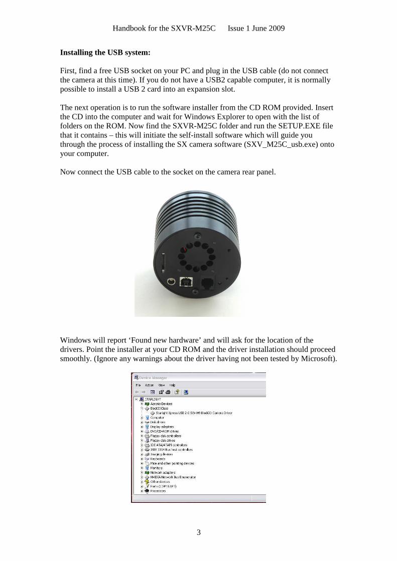
Now connect the USB cable to the socket on the camera rear panel.
Windows will report ‘Found new hardware’ and will ask for the location of thedrivers. Point the installer at your CD ROM and the driver installation should proceedsmoothly. (Ignore any warnings about the driver having not been tested by Microsoft).
Handbook for the SXVR-M25C Issue 1 June 2009
4
At the end of this process, the USB interface will be installed as a ‘BlockIOClassdevice’ and the camera software will be able to access it. You can confirm that theinstallation is complete by checking the status of the USB devices in the Windows‘Device Manager’ (see above). Start up the Windows ‘Control Panel’ and select‘System’. Now click on the tab labelled ‘Device Manager’, ‘Hardware’, and all of thesystem devices will be displayed in a list (see above). If the installation is successful,there will be a diamond shaped symbol labelled ‘BlockIOClass’ and clicking on the‘+’ sign will reveal it to be a ‘Starlight Xpress USB 2.0 SXV-M25C BlockIO cameradriver’. If this device shows as faulty, try clicking on it and selecting ‘properties’ andthen ‘update driver’. Following the on screen instructions will allow you to re-selectthe correct inf file (SXVIO_M25C_325.inf) and driver files (SXVIO.sys andgeneric.sys), which should fix the problem.
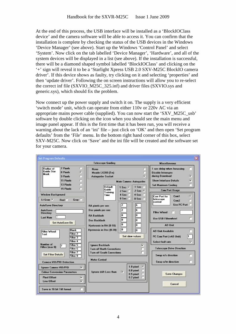
Now connect up the power supply and switch it on. The supply is a very efficient‘switch mode’ unit, which can operate from either 110v or 220v AC via anappropriate mains power cable (supplied). You can now start the ‘SXV_M25C_usb’software by double clicking on the icon when you should see the main menu andimage panel appear. If this is the first time that it has been run, you will receive awarning about the lack of an ‘ini’ file – just click on ‘OK’ and then open ‘Set programdefaults’ from the ‘File’ menu. In the bottom right hand corner of this box, selectSXV-M25C. Now click on ‘Save’ and the ini file will be created and the software setfor your camera.
Handbook for the SXVR-M25C Issue 1 June 2009
5
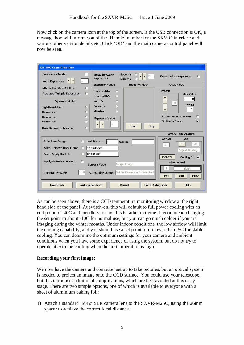
Now click on the camera icon at the top of the screen. If the USB connection is OK, amessage box will inform you of the ‘Handle’ number for the SXVIO interface andvarious other version details etc. Click ‘OK’ and the main camera control panel willnow be seen.
As can be seen above, there is a CCD temperature monitoring window at the righthand side of the panel. At switch-on, this will default to full power cooling with anend point of -40C and, needless to say, this is rather extreme. I recommend changingthe set point to about -10C for normal use, but you can go much colder if you areimaging during the winter months. Under indoor conditions, the low airflow will limitthe cooling capability, and you should use a set point of no lower than -5C for stablecooling. You can determine the optimum settings for your camera and ambientconditions when you have some experience of using the system, but do not try tooperate at extreme cooling when the air temperature is high.
Recording your first image:
We now have the camera and computer set up to take pictures, but an optical systemis needed to project an image onto the CCD surface. You could use your telescope,but this introduces additional complications, which are best avoided at this earlystage. There are two simple options, one of which is available to everyone with asheet of aluminium baking foil:
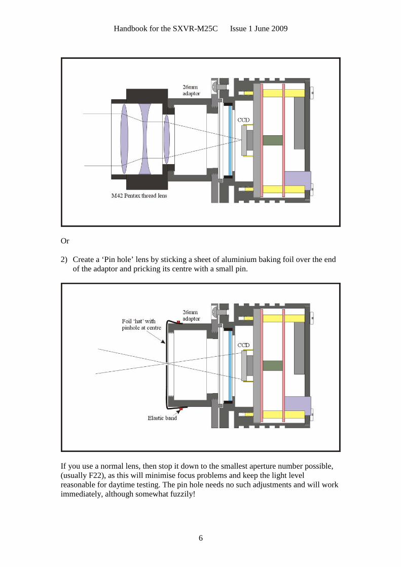
1) Attach a standard ‘M42’ SLR camera lens to the SXVR-M25C, using the 26mmspacer to achieve the correct focal distance.
Handbook for the SXVR-M25C Issue 1 June 2009
6
Or
2) Create a ‘Pin hole’ lens by sticking a sheet of aluminium baking foil over the endof the adaptor and pricking its centre with a small pin.
If you use a normal lens, then stop it down to the smallest aperture number possible,(usually F22), as this will minimise focus problems and keep the light levelreasonable for daytime testing. The pin hole needs no such adjustments and will workimmediately, although somewhat fuzzily!

Handbook for the SXVR-M25C Issue 1 June 2009
7
Point the camera + lens or pinhole towards a well-lit and clearly defined object somedistance away. Now enter the ‘File’ menu in the SXV_M25C software and click on‘SX camera interface’. Select an exposure time of 0.1 seconds and press ‘Take Photo’.
After the exposure and download have completed (about 1 second) an image of somekind will appear on the computer monitor. It will probably be poorly focused andincorrectly exposed, but any sort of image is better than none! In the case of thepinhole, all that you can experiment with is the exposure time, but a camera lens canbe adjusted for good focus and so you might want to try this to judge the high imagequality that it is possible to achieve.
Various other exposure options are available, as can be seen in the picture above. Forexample, you can ‘Bin’ the download 2x2, or more, to achieve greater sensitivity andfaster download, or enable ‘Continuous mode’ to see a steady stream of images.‘Focus mode’ downloads a 128 x 128 segment of the image at high speed. The initialposition of the segment is central to the frame, but can be moved by selecting ‘Focusframe centre’ in the ‘File’ menu and clicking the desired point with the mouse. Thefocus window has an adjustable ‘contrast stretch’, controlled by the 12-16 bit slider.The image will be ‘normal’ if 16 bits is selected, while setting lower values willincrease the image brightness in inverse proportion.
If you cannot record any kind of image, please check the following points:
1) Ensure that the power indicator lamp is on and that the cables are properly homein their sockets.
2) If the screen is completely white, the camera may be greatly overexposed. Try ashorter exposure time, or stop down your lens. See if covering the lens causes theimage to darken.
3) If the USB did not initialise properly, the camera start-up screen will tell you thatthe connection is defective. Try switching off the power supply and unplugging theUSB cable. Now turn the power supply on and plug in the USB cable. This will re-load the USB software and may fix the problem after restarting theSXV_M25C_usb program. Otherwise, check the device driver status, as previouslydescribed, and re-install any drivers which appear to be defective.
4) If you cannot find any way of making the camera work, please try using it withanother computer. This will confirm that the camera is OK, or faulty, and you canthen decide how to proceed. Our guarantee ensures that any electrical faults arecorrected quickly and at no cost to the customer.
Converting your images to colour:
The images from your camera are monochrome at the moment and they need to beconverted into true colour before enhancing them. Any processing of the image, otherthan calibration with dark frames etc., will distort the colour rendering of the resultand so the conversion needs to be done before proceeding. Important! You cannotconvert a binned image to colour, as binning sums the different colour pixels togetherand averages out the colour information. All images that you intend to colour convertmust be taken in binned 1x1 mode. Also please note that you cannot sum framestogether before colour conversion. This must be done after the images have beencolour converted.
Handbook for the SXVR-M25C Issue 1 June 2009
8
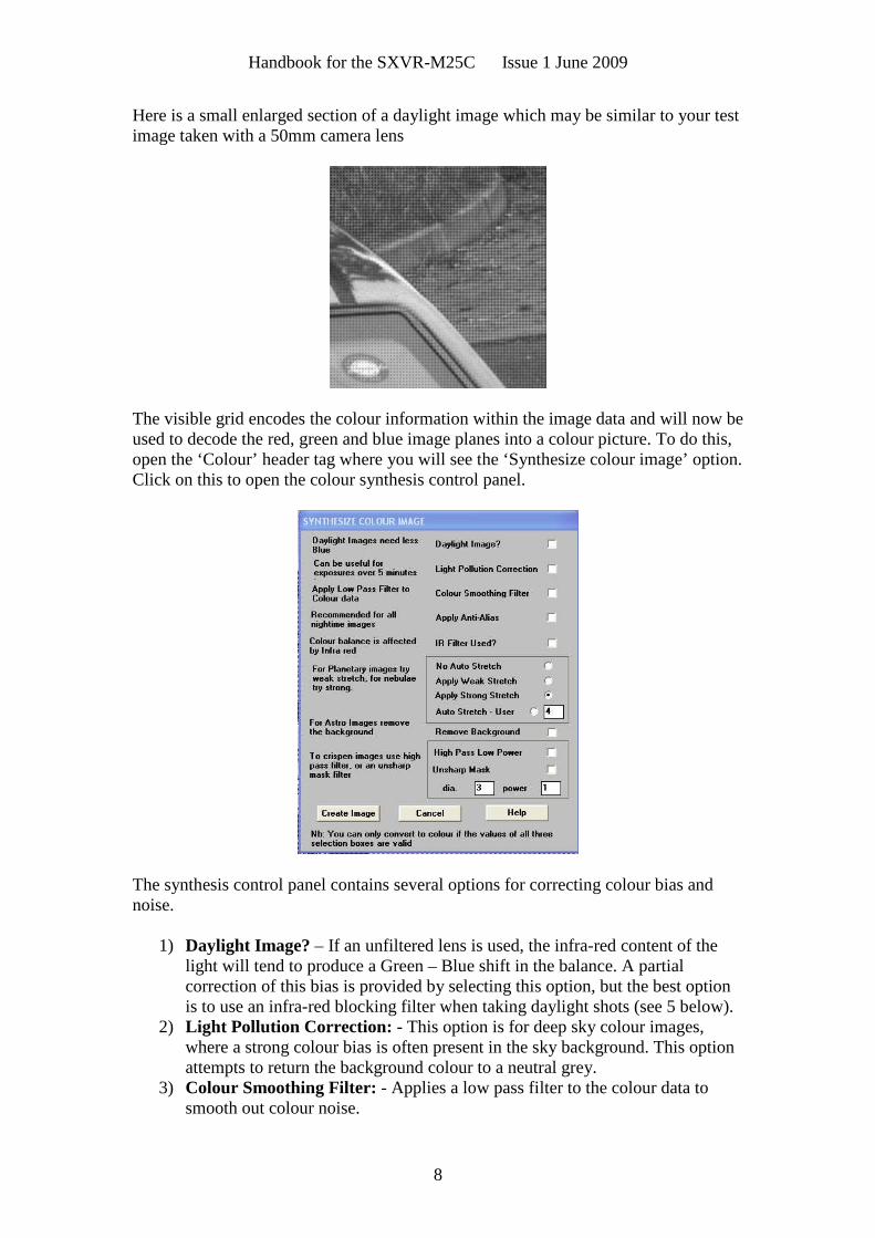
Here is a small enlarged section of a daylight image which may be similar to your testimage taken with a 50mm camera lens
The visible grid encodes the colour information within the image data and will now beused to decode the red, green and blue image planes into a colour picture. To do this,open the ‘Colour’ header tag where you will see the ‘Synthesize colour image’ option.Click on this to open the colour synthesis control panel.
The synthesis control panel contains several options for correcting colour bias andnoise.
1) Daylight Image? – If an unfiltered lens is used, the infra-red content of thelight will tend to produce a Green – Blue shift in the balance. A partialcorrection of this bias is provided by selecting this option, but the best optionis to use an infra-red blocking filter when taking daylight shots (see 5 below).
2) Light Pollution Correction: - This option is for deep sky colour images,where a strong colour bias is often present in the sky background. This optionattempts to return the background colour to a neutral grey.
3) Colour Smoothing Filter: - Applies a low pass filter to the colour data tosmooth out colour noise.
Handbook for the SXVR-M25C Issue 1 June 2009
9
4) Apply Anti-Alias: - Runs a special filter over the colour data to removecoloured artefacts around sharp edges. This is especially useful for cleaning uperratically coloured star images.
5) IR Filter Used? – Sets the colour balance to allow for the loss of infra-redcontent when using an IR blocking filter.
6) Stretching: - A selection of contrast-boosting options which are preset forvarious subjects.
7) Remove Background: - This option will adjust the sky background brightnessto give an optimum background level.
8) High Pass filters: - Automatically sharpen the luminance data to emphasisefine details. Most useful for sharpening planetary images but will also increasethe noise content.
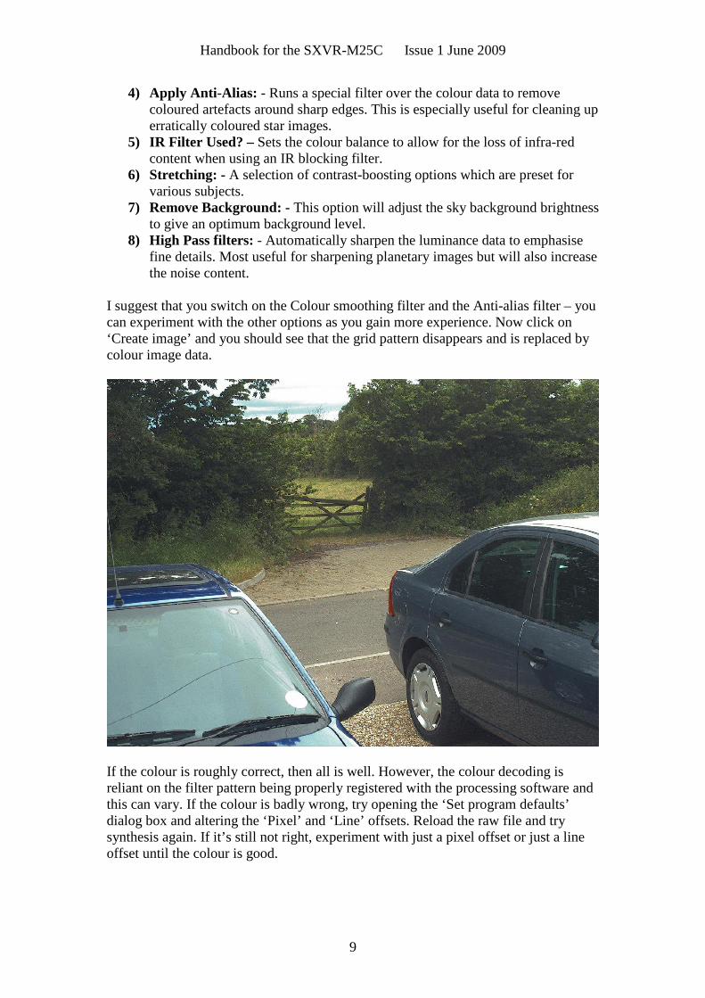
I suggest that you switch on the Colour smoothing filter and the Anti-alias filter – youcan experiment with the other options as you gain more experience. Now click on‘Create image’ and you should see that the grid pattern disappears and is replaced bycolour image data.
If the colour is roughly correct, then all is well. However, the colour decoding isreliant on the filter pattern being properly registered with the processing software andthis can vary. If the colour is badly wrong, try opening the ‘Set program defaults’dialog box and altering the ‘Pixel’ and ‘Line’ offsets. Reload the raw file and trysynthesis again. If it’s still not right, experiment with just a pixel offset or just a lineoffset until the colour is good.
Handbook for the SXVR-M25C Issue 1 June 2009
10
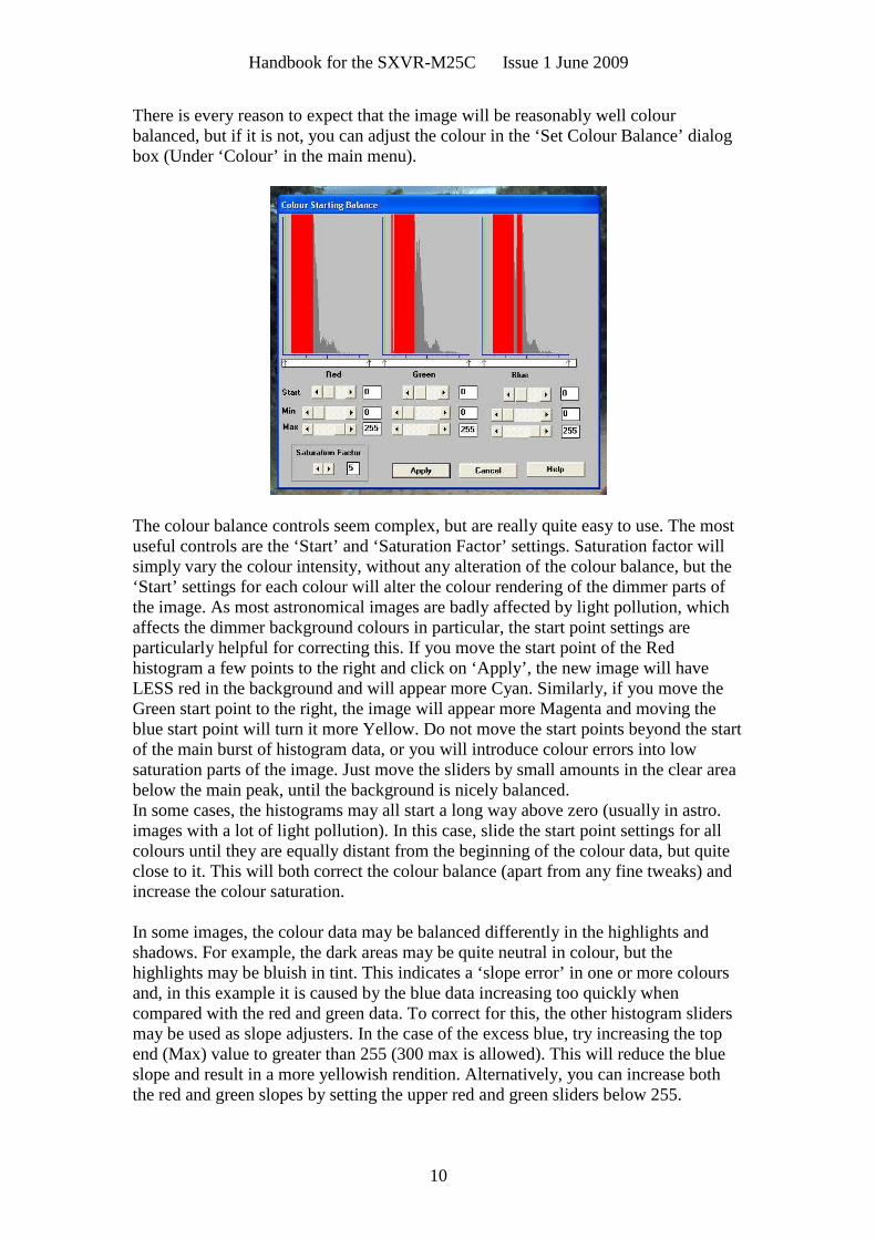
There is every reason to expect that the image will be reasonably well colourbalanced, but if it is not, you can adjust the colour in the ‘Set Colour Balance’ dialogbox (Under ‘Colour’ in the main menu).
The colour balance controls seem complex, but are really quite easy to use. The mostuseful controls are the ‘Start’ and ‘Saturation Factor’ settings. Saturation factor willsimply vary the colour intensity, without any alteration of the colour balance, but the‘Start’ settings for each colour will alter the colour rendering of the dimmer parts ofthe image. As most astronomical images are badly affected by light pollution, whichaffects the dimmer background colours in particular, the start point settings areparticularly helpful for correcting this. If you move the start point of the Redhistogram a few points to the right and click on ‘Apply’, the new image will haveLESS red in the background and will appear more Cyan. Similarly, if you move theGreen start point to the right, the image will appear more Magenta and moving theblue start point will turn it more Yellow. Do not move the start points beyond the startof the main burst of histogram data, or you will introduce colour errors into lowsaturation parts of the image. Just move the sliders by small amounts in the clear areabelow the main peak, until the background is nicely balanced.In some cases, the histograms may all start a long way above zero (usually in astro.images with a lot of light pollution). In this case, slide the start point settings for allcolours until they are equally distant from the beginning of the colour data, but quiteclose to it. This will both correct the colour balance (apart from any fine tweaks) andincrease the colour saturation.
In some images, the colour data may be balanced differently in the highlights andshadows. For example, the dark areas may be quite neutral in colour, but thehighlights may be bluish in tint. This indicates a ‘slope error’ in one or more coloursand, in this example it is caused by the blue data increasing too quickly whencompared with the red and green data. To correct for this, the other histogram slidersmay be used as slope adjusters. In the case of the excess blue, try increasing the topend (Max) value to greater than 255 (300 max is allowed). This will reduce the blueslope and result in a more yellowish rendition. Alternatively, you can increase boththe red and green slopes by setting the upper red and green sliders below 255.

Handbook for the SXVR-M25C Issue 1 June 2009
11
Image enhancements:
Your first image may be satisfactory, but it is unlikely to be as clear and sharp as itcould be. Improved focusing and exposure selection may correct these shortcomings,and you may like to try them before applying any image enhancement with thesoftware. However, there will come a point when you say, “That’s the best that I canget” and you will want to experiment with the effects of image processing. In the caseof daylight images, the processing options are many, but there are few that willimprove the picture in a useful way. The most useful of these are the ‘NormalContrast Stretch’ and the ‘High Pass Low Power’ filter. The high pass filter gives amoderate improvement in the image sharpness, and this can be very effective ondaylight images.
Too much high pass filtering results in dark borders around well-defined features andwill increase the noise in an image to unacceptable levels, but the Low Power filter isclose to optimum and gives a nicely sharpened picture.
The ‘Contrast’ routines are used to brighten (or dull) the image highlights andshadows. A ‘Normal’ stretch is a simple linear operation, where two pointers (the‘black’ and ‘white’ limits) can be set at either side of the image histogram and used todefine new start and end points. The image data is then mathematically modified sothat any pixels that are to the left of the ‘black’ pointer are set to black and any pixelsto the right of the ‘white’ pointer are set to white. The pixels with values between thepointers are modified to fit the new brightness distribution. Try experimenting withthe pointer positions until the image has a pleasing brightness and ‘crispness’.
At this point, you will have a working knowledge of how to take and process anSXVR-M25C image. It is time to move on to astronomical imaging, which has itsown, unique, set of problems!
*********************************************************************
Astronomical Imaging with the SXVR-M25C
1) Getting the image onto the CCD:
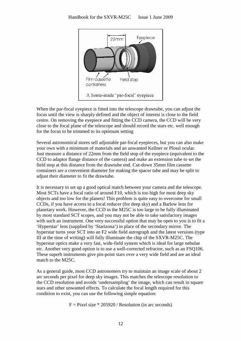
It is fairly easy to find the correct focus setting for the camera when using a standardSLR lens, but quite a different matter when the SXVR-M25C is attached to atelescope! The problem is that most telescopes have a large range of focus adjustmentand the CCD needs to be quite close to the correct position before you can discerndetails well enough to optimise the focus setting. An additional complication is theneed to add various accessories between the camera and telescope in order that theimage scale is suitable for the subject being imaged and (sometimes) to include a ‘flipmirror’ finder unit for visual object location.A simple, but invaluable device, is the ‘par-focal eyepiece’. This is an eyepiece inwhich the field stop is located at the same distance from the barrel end, as the CCD isfrom the camera barrel end.
Handbook for the SXVR-M25C Issue 1 June 2009
12
When the par-focal eyepiece is fitted into the telescope drawtube, you can adjust thefocus until the view is sharply defined and the object of interest is close to the fieldcentre. On removing the eyepiece and fitting the CCD camera, the CCD will be veryclose to the focal plane of the telescope and should record the stars etc. well enoughfor the focus to be trimmed to its optimum setting
Several astronomical stores sell adjustable par-focal eyepieces, but you can also makeyour own with a minimum of materials and an unwanted Kellner or Plossl ocular.Just measure a distance of 22mm from the field stop of the eyepiece (equivalent to theCCD to adaptor flange distance of the camera) and make an extension tube to set thefield stop at this distance from the drawtube end. Cut-down 35mm film cassettecontainers are a convenient diameter for making the spacer tube and may be split toadjust their diameter to fit the drawtube.
It is necessary to set up a good optical match between your camera and the telescope.Most SCTs have a focal ratio of around F10, which is too high for most deep skyobjects and too low for the planets! This problem is quite easy to overcome for smallCCDs, if you have access to a focal reducer (for deep sky) and a Barlow lens forplanetary work. However, the CCD in the M25C is too large to be fully illuminatedby most standard SCT scopes, and you may not be able to take satisfactory imageswith such an instrument. One very successful option that may be open to you is to fit a‘Hyperstar’ lens (supplied by ‘Starizona’) in place of the secondary mirror. Thehyperstar turns your SCT into an F2 wide field astrograph and the latest versions (typeIII at the time of writing) will fully illuminate the chip of the SXVR-M25C. Thehyperstar optics make a very fast, wide-field system which is ideal for large nebulaeetc. Another very good option is to use a well-corrected refractor, such as an FSQ106.These superb instruments give pin-point stars over a very wide field and are an idealmatch to the M25C.
As a general guide, most CCD astronomers try to maintain an image scale of about 2arc seconds per pixel for deep sky images. This matches the telescope resolution tothe CCD resolution and avoids ‘undersampling’ the image, which can result in squarestars and other unwanted effects. To calculate the focal length required for thiscondition to exist, you can use the following simple equation:
F = Pixel size * 205920 / Resolution (in arc seconds)
Handbook for the SXVR-M25C Issue 1 June 2009
13
In the case of the SXVR-M25C and a 2 arc seconds per pixel resolution, we get
F = 0.0074 * 205920 / 2 = 664mm
For a 200mm SCT, this is an F ratio of 664 / 200 = F3.32, which is rather less thancan be achieved with the Meade converter and appropriate extension tube. However,moderate deviations from this focal length will not have a drastic effect and so any Fratio from about F4.5 to F6.3 will give good results.
The same equation can be used to calculate the amplification required for goodplanetary images. However, in this case, the shorter exposures allow us to assume amuch better telescope resolution and 0.25 arc seconds per pixel is a good value to use.The calculation now gives the following result:
F = 0.0074 * 205920 / 0.25 = 5354mm
This is approximately F27 when used with a 200mm SCT and so we will need a 2.8xBarlow lens and the common 3x version will be good enough for all practicalpurposes. Barlow lenses are less critical than focal reducers and most types can beused with good results. However, if you are buying one especially for CCD imaging, Irecommend getting a 3x or 5x amplifier, or the planets will still be rather small inyour images.
Achieving a good focus:
Your starting point will depend on the focus aids, if any, which you are using. Withthe par-focal eyepiece, you should slip the eyepiece into the drawtube and focusvisually on a moderately bright star (about 3rd magnitude). Now withdraw theeyepiece and carefully insert the camera nosepiece, until it is bottomed against thedrawtube end, and then lock it in place.
SXV_M25C_usb.exe has a focus routine that will repeatedly download and display a128 x 128 pixel segment of the image at relatively high speed. This focus windowmay be positioned anywhere in the camera field and can be displayed with anadjustable degree of automatic contrast stretching (for focusing on faint stars). To usethis mode, start up the software and select the SXV camera interface (File menu). Setthe camera mode to Binned 1x1 and select an exposure time of 1 second. Press ‘TakePicture’ and wait for the image to download. There is a good chance that yourselected star will appear somewhere within the image frame and it should be close toa sharp focus. If the focus is still poor, then it may appear as a pale disk of light, oftenwith a dark centre (the secondary mirror shadow in an SCT, or Newtonian). Nowselect the ‘File’ menu again and click on ‘Focus frame centre’; you can now use themouse pointer to click on the star image and the new focus frame co-ordinates will bedisplayed. Now return to the camera interface window and click on ‘Start’ in theFocus frame. The computer will now display a continuous series of 128 x 128 pixelimages in the focus window and you should see your selected star appear somewhereclose to the centre. A ‘peak value’ (the value of the brightest pixel) will also be shownin the adjacent text box and this can be used as an indication of the focus accuracy.

Handbook for the SXVR-M25C Issue 1 June 2009
14
Although the peak value is sensitive to vibration and seeing, it tends towards amaximum as the focus is optimised. Carefully adjust the focus control on yourtelescope until the image is as sharp as possible and the peak value reaches amaximum. Wait for any vibration to die down before accepting the reading as reliableand watch out for bursts of bad seeing, which reduce the apparent focus quality. Quiteoften, the peak value will increase to the point where it is ‘off scale’ at 4095 and inthis case you must halt the focus sequence and select a shorter exposure if you wish touse the peak value as an indicator. Once you are happy with the focus qualityachieved, you might like to trim the settings of your par-focal or flip mirror eyepieceto match the current camera position.Although you can reach a good focus by the above method, many observers prefer touse additional aids, such as Hartmann or Bahnitov masks (an objective cover withseveral spaced holes) or diffraction bars (narrow parallel rods across the telescopeaperture). These make the point of precise focus easier to determine by creating‘double images’ or bright diffraction spikes around stars, which merge at the settingof exact focus. The 12-16 bit slider control allows you to adjust the contrast of thefocus frame for best visibility of the star image. It defaults to maximum stretch (12bits), which is generally ideal for stars, but a lower stretch value is better for focusingon planets.
Taking your first astronomical image:
I will assume that you are now set up with a focused camera attached to a telescopewith an operating sidereal drive. If so, you are now in a position to take a moderatelylong exposure of some interesting deep-sky astronomical object (I will deal withplanets later). As most drives are not very accurate beyond a minute or two ofexposure time, I suggest that you find a fairly bright object to image, such as M42,M13, M27 or M57. There are many others to choose from, but these are goodexamples.
Use the finder to align on your chosen object and then centre accurately by using thefocus frame and a short exposure of between 1 and 5 seconds. The ’12-16 bit’ sliderin the focus frame allows you to adjust the image contrast if you find that the object istoo faint with a short exposure. Once properly centred and focused, take an exposureof about 60 seconds, and observe the result. Initially, the image may appear ratherbarren and show only a few stars, however, there is a great deal of data hidden fromview. You can get to see a lot of this, without affecting the image data, if you go tothe ‘View’ menu and select ‘Auto Contrast Stretch Image’. The faint image data willthen appear in considerable detail and I think that you will be impressed by the result!
If you are happy with the image, go to the ‘File’ menu and save it in a convenientdirectory.
Most competitive brands of CCD camera require a ‘dark frame’ to be subtracted fromyour images to achieve the best results. A dark frame is simply a picture which wastaken with the same exposure as your ‘light frame’, but with the telescope objectivecovered, so that no light can enter. It records only the ‘hot pixels’ and thermalgradients of your CCD, so that these defects are largely removed when the dark frameis subtracted from the light frame. The SXVR-M25C CCD is quite different fromthose used in other brands of camera and generates an extremely low level of dark
Handbook for the SXVR-M25C Issue 1 June 2009
15
noise. Indeed, it is so low that subtracting a dark frame can actually INCREASE thenoise in your images! This is because the statistical noise of the dark frame canexceed the ‘pattern noise’ from warm pixels and hence add to that of the subtractedresult. If your test pictures have an exposure time of less than about 10 minutes (asabove), then don’t bother with a dark frame, just ‘kill’ any hot pixels with yourprocessing software. In SXVR-M25C, the ‘Median filter’ can do this, but othersoftware (e.g. Maxim DL) will provide a ‘hot pixel killer’ that can be mapped tospecific locations in the image, or methods such as ‘Sigma combine’ may be used.
In the unlikely event that you feel that dark frame really is necessary, please proceedas follows:
To take a dark frame, just cover the telescope objective with the lens cap and takeanother exposure with the same length as that of the light frame. This image will be apicture of the dark signal generated during your exposure and it should be saved withyour image for use in processing the picture. If many such darks are recorded andaveraged together, the statistical noise will be reduced, but the gains to be had arerather small compared with the effort involved.
As variations in ambient temperature will affect the dark signal, it is best to take thedark frames within a few minutes of capturing your images. For the same reason, it isnot wise to use ‘old’ dark frames if you want the best possible results, however, somesoftware allows you to scale library dark frames to match the image (e.g. AstroArt)and this can be useful as a time saver.
‘Bias frames’ are somewhat more useful than dark frames when using the SXVR-M25C. A bias frame is essentially a zero exposure dark frame and records any minorreadout defects that the CCD may possess, so a ‘bias frame subtraction’ can clean upany ‘warm columns’ or shadings that are created during readout. To record a biasframe, cover the camera aperture and take a 1000th of a second exposure. If you takeat least 10 such frames and average them together, the resulting ‘master bias’ can beused to clean up readout defects for many months before CCD ageing changes requireanother set to be recorded.
‘Flat fields’ are often recommended for optimising the results from your CCDcamera, but these are generally less important than dark frames, especially if youmake sure that the optical window of the camera is kept dust-free. The purpose of aflat field is to compensate for uneven illumination and sensitivity of the CCD and it isbetter to avoid the need for one by keeping the optics clean and unvignetted. I willignore flat fielding for current purposes and describe the process in detail at a laterstage.
Processing a deep-sky image:
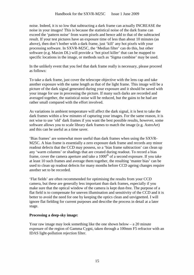
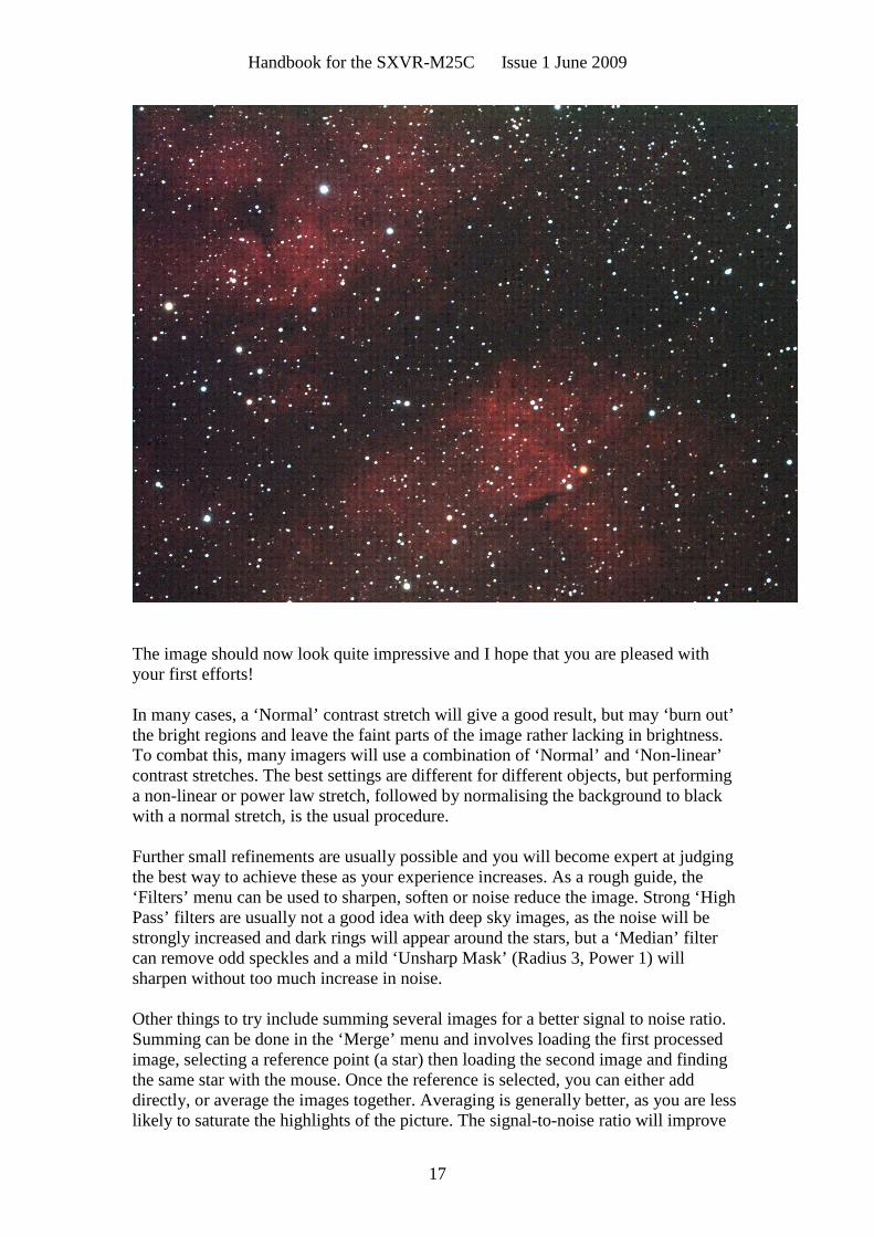
Your raw image may look something like the one shown below – a 20 minuteexposure of the region of Gamma Cygni, taken through a 100mm F5 refractor with anIDAS light-pollution rejection filter.
Handbook for the SXVR-M25C Issue 1 June 2009
16
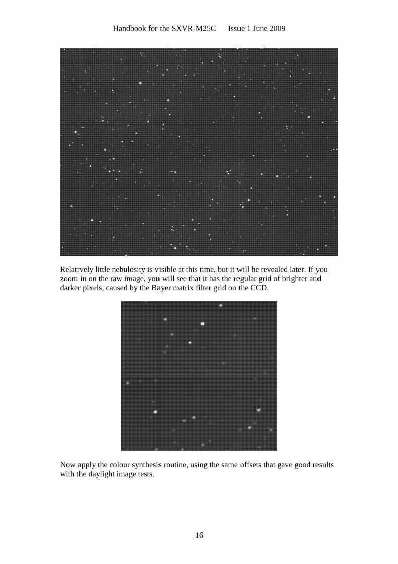
Relatively little nebulosity is visible at this time, but it will be revealed later. If youzoom in on the raw image, you will see that it has the regular grid of brighter anddarker pixels, caused by the Bayer matrix filter grid on the CCD.
Now apply the colour synthesis routine, using the same offsets that gave good resultswith the daylight image tests.
Handbook for the SXVR-M25C Issue 1 June 2009
17
The image should now look quite impressive and I hope that you are pleased withyour first efforts!
In many cases, a ‘Normal’ contrast stretch will give a good result, but may ‘burn out’the bright regions and leave the faint parts of the image rather lacking in brightness.To combat this, many imagers will use a combination of ‘Normal’ and ‘Non-linear’contrast stretches. The best settings are different for different objects, but performinga non-linear or power law stretch, followed by normalising the background to blackwith a normal stretch, is the usual procedure.
Further small refinements are usually possible and you will become expert at judgingthe best way to achieve these as your experience increases. As a rough guide, the‘Filters’ menu can be used to sharpen, soften or noise reduce the image. Strong ‘HighPass’ filters are usually not a good idea with deep sky images, as the noise will bestrongly increased and dark rings will appear around the stars, but a ‘Median’ filtercan remove odd speckles and a mild ‘Unsharp Mask’ (Radius 3, Power 1) willsharpen without too much increase in noise.
Other things to try include summing several images for a better signal to noise ratio.Summing can be done in the ‘Merge’ menu and involves loading the first processedimage, selecting a reference point (a star) then loading the second image and findingthe same star with the mouse. Once the reference is selected, you can either adddirectly, or average the images together. Averaging is generally better, as you are lesslikely to saturate the highlights of the picture. The signal-to-noise ratio will improve

Handbook for the SXVR-M25C Issue 1 June 2009
18
at a rate proportional to the square root of the number of summations (summing 4images will double the signal-to-noise), but different exposures must be used.Summing an image with itself will not improve the S/N ratio!
Although I have concentrated on the use of a telescope for deep-sky imaging, do notforget that you have the option of using an ordinary camera lens for impressive wide-field shots! A good quality 200mm F3.5 lens with an infrared blocking filter will yieldvery nice images of large objects, such as M31, M42, M45 etc. If you cannot obtain alarge IR blocker for the front of the lens, it is quite acceptable to place a small onebehind the lens, inside the adaptor tube. You can even try using a hydrogen-alphafilter to bring out nebulae, reduce light pollution and sharpen the star images to pin-points, although the results will be monochrome red!
Taking pictures of the planets:
The SXVR-M25C has a large CCD with 6 million pixels and so it is not well suited toplanetary imaging, where a small CCD is ideal. However, it can be used if you acceptthe relatively large amount of wasted image area, or use a sub-frame download.
Planetary imaging is in many ways quite different from deep sky imaging. Most deepsky objects are faint and relatively large, so a short focal length and a long exposureare needed, while planets are bright and very small, needing long focal lengths andshort exposures. High resolution is critical to achieving good results and I havealready shown how a suitable focal length can be calculated and produced, using aBarlow lens.
Many camera users comment on the difficulty of finding the correct focus whentaking pictures of Jupiter etc. This is usually due to poor seeing conditions, which areonly too common, but may also be due in part to poor collimation of your telescope.Please ensure that the optics are properly aligned as shown by star testing, or by usingone of the patent collimation aids that are widely available. It is also better to use astar for initial focusing, as planetary detail is difficult to judge in bad seeing. Althoughthe star will also suffer from blurring, the eye can more easily gauge when the mostcompact blur has been achieved!
You could begin by imaging lunar craters, or the planets, Jupiter, Saturn or Mars. Therapid variations of seeing which accompany planetary imaging, will ruin thedefinition of about 95% of your images and so I recommend setting the camera to runin ‘Autosave’ mode. This will automatically take a sequence of images and save themwith sequential file names in your ‘Autosave’ directory. Dozens of images will besaved, but only one or two will be satisfactory for further processing. The ‘Subframe’mode of the SXVR may be found useful for limiting the wasted area and reducing thedownload time of small planetary images.
To start the Autosave process, call up the SXVR Camera Interface and select the‘Continuous Mode’ check box at the top (make sure the rest are unchecked). Nowcheck the ‘Autosave Image’ checkbox near the bottom of the window. If you nowclick on ‘Take Picture’ the automatic sequence will begin and will not stop until youpress a computer key. The images will be saved in FITs format with sequential names

Handbook for the SXVR-M25C Issue 1 June 2009
19
such as ‘Img23, Img24….’ and will be found in the ‘Autosave’ directory (or a sub-directory of Autosave, set up in the program defaults menu).
The exposure time needed for good planetary images is such that the image histogramhas a peak value at around 200 and does not extend much above 220 (Ignore themajor peak near zero, due to the dark background). If you use too short an exposuretime, the image noise level will be increased, and if too long a time is used you willsaturate the highlights and cause white patches on the image. With the recommendedfocal length, Jupiter and Mars will both need an exposure time of between 0.1 and 1seconds and Saturn will need between 0.5 and 2 seconds.
Processing a planetary image:
Planetary images have one major advantage over deep sky images, when you come toprocess them – they are MUCH brighter, with a correspondingly better signal to noiseratio. This means that aggressive sharpening filters may be used without making theresult look very noisy and so some of the effects of poor seeing can be neutralised.
A raw image
Try applying an ‘Unsharp Mask’ filter with a radius of 5 and a power of 5. This willgreatly increase the visibility of any detail on the planet, but the optimum radius andpower will have to be determined by experiment.
Jupiter after the application of an ‘Unsharp mask’
In general terms, the larger the image and the worse the seeing, then the wider theradius for best results. My Jupiter shots are usually about one third the height of theCCD frame and I find that the ‘radius 5, power 5’ values are good for most averageseeing conditions. If you have exceptionally good conditions, then a reduction to R=3,P=3 will probably give a more natural look to the image, as too large a radius andpower tends to outline edges with dark or bright borders.
Handbook for the SXVR-M25C Issue 1 June 2009
20
As a finishing touch, the application of a Median filter or a Weighted Mean Low Passfilter can be useful to smooth out the high frequency noise after a strong UnsharpMask.
As with deep-sky images, it is advantageous to sum planetary images together toimprove the signal to noise ratio. In this case, the ‘averaging’ option should always beused, or the result is likely to exceed the dynamic range of the software and saturatethe highlights. Aligning the images is always something of a problem, as there arerarely any stars to use when imaging the planets, but Jupiter’s satellites can be usefulreference points. Otherwise, you will have to find a well-defined feature on the planet,or estimate where the centre of the disk is located. Some more sophisticated softwarecan automatically align planetary images and you may find these programs (e.g.‘Registax’) to be very useful.
*********************************************************************
Using the add-on autoguider:
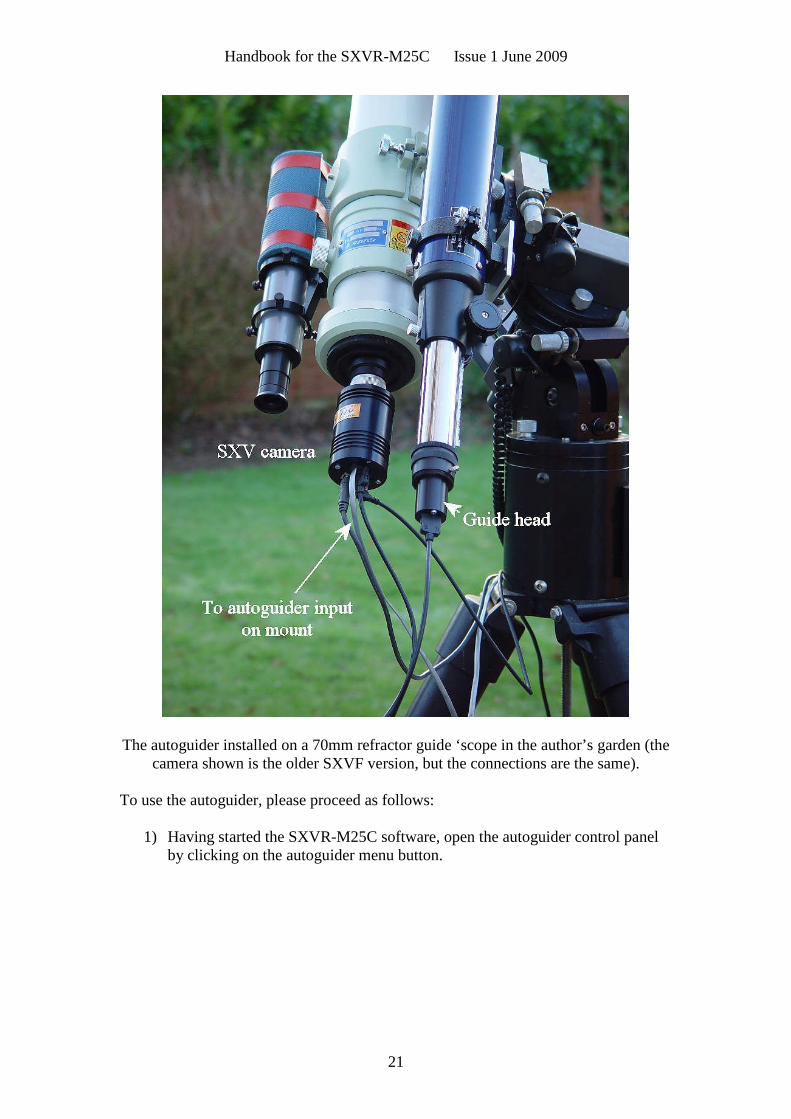
A very useful accessory is the add-on autoguider head, which takes its power andcontrol signals directly from the SXVR camera, via the 18 way socket on its rearpanel. The autoguider is only 1.25” in diameter and has a video style ‘CS’ mountthread in its nose, so video lenses may be attached. The guider may be used witheither an off-axis prism assembly mounted in front of the SXVR camera, or with aseparate guide telescope, rigidly mounted alongside your imaging telescope. Ipersonally use it with a 70mm aperture, F10, inexpensive refractor as a guide ‘scope,but a shorter focal length lens will make more guide stars available in any givenregion of sky (See the picture below).
To use the autoguider, first orient it so that the connector plug is roughly parallel tothe declination axis of your mount. This is not absolutely essential, as the trainingroutine will learn the angle of the head and compensate for it, but it is easier tounderstand the motion of the guide star if the guider frame is aligned with the RA andDec axes. Now connect the head to the camera, using the 18 way connector lead,including the port divider box, if it is to be used.
The recommended way of connecting the autoguider output to the mount is to use anRJ11 telephone lead between the socket on the SXV camera and the autoguider inputof your mount. This output is ‘active low’ (i.e. the control relays pull the guider inputsdown to zero volts when applying a guide correction) and matches most of theautoguider inputs on commercial mounts. If ‘active high’ inputs are needed, or a verylow control voltage drop is essential, then you will need to add a Starlight Xpress‘relay box’ between the guider output and the input to the mount. Please contact yourlocal distributor if a relay box is required. Some mounts (Vixen, for example) use asimilar guider input socket, but have re-arranged connections. Details are given on ourweb pages at the end of the ‘STAR2000’ section.
Handbook for the SXVR-M25C Issue 1 June 2009
21
The autoguider installed on a 70mm refractor guide ‘scope in the author’s garden (thecamera shown is the older SXVF version, but the connections are the same).
To use the autoguider, please proceed as follows:
1) Having started the SXVR-M25C software, open the autoguider control panelby clicking on the autoguider menu button.
Handbook for the SXVR-M25C Issue 1 June 2009
22
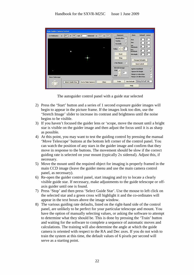
The autoguider control panel with a guide star selected
2) Press the ‘Start’ button and a series of 1 second exposure guider images willbegin to appear in the picture frame. If the images look too dim, use the‘Stretch Image’ slider to increase its contrast and brightness until the noisebegins to be visible.
3) If you haven’t focused the guider lens or ‘scope, move the mount until a brightstar is visible on the guider image and then adjust the focus until it is as sharpas possible.
4) At this point, you may want to test the guiding control by pressing the manual‘Move Telescope’ buttons at the bottom left corner of the control panel. Youcan watch the position of any stars in the guider image and confirm that theymove in response to the buttons. The movement should be slow if the correctguiding rate is selected on your mount (typically 2x sidereal). Adjust this, ifnecessary.
5) Move the mount until the required object for imaging is properly framed in themain CCD image (leave the guider menu and use the main camera controlpanel, as necessary).
6) Re-open the guider control panel, start imaging and try to locate a clearlyvisible guide star. If necessary, make adjustments to the guide telescope or off-axis guider until one is found.
7) Press ‘Stop’ and then press ‘Select Guide Star’. Use the mouse to left click onthe selected star and a green cross will highlight it and the co-ordinates willappear in the text boxes above the image window.
8) The various guiding rate defaults, listed on the right-hand side of the controlpanel, are unlikely to be perfect for your particular telescope and mount. Youhave the option of manually selecting values, or asking the software to attemptto determine what they should be. This is done by pressing the ‘Train’ buttonand waiting for the software to complete a sequence of automatic moves andcalculations. The training will also determine the angle at which the guidecamera is oriented with respect to the RA and Dec axes. If you do not wish totrain the system at this time, the default values of 6 pixels per second willserve as a starting point.

Handbook for the SXVR-M25C Issue 1 June 2009
23
9) Now press ‘Go to main camera’ and the guider control panel will be replacedby the camera control panel. Set the required exposure time for the image (say5 minutes) and press the ‘Autoguide next image’ button. The autoguiderwindow will reappear and, after a few seconds, you should see error valuesappearing in the text windows at the top. The guide star will be fairly close tothe green cross, although not necessarily accurately centred, and you shouldsee the power/ guide LED on the rear of the camera brighten and changecolour with each correction.
10) If the star begins to drift away from the cross, despite the corrections beingmade, the chances are that the N/S and/or E/W directions are set wrongly.Judge which axis is incorrectly set by observing the direction of the drift andthen stop the exposure by pressing ‘Esc’. Open the guider control panel andcheck the appropriate swap box(es). After this operation, you will probablyneed to find the guide star again by taking a guider image and reselecting thestar, as before. Now return to the main camera menu and try the ‘Autoguidenext image’ button again.
11) Once guiding is taking place without problems, the main exposure can beallowed to finish and, if all is well, you should see an image with tiny circularstars.
If the stars are not circular, you may need to alter the guiding parameters, orinvestigate the rigidity and drive performance of your mount. A lot of informationcan be deduced by watching the behaviour of the guide star in the guider frame. Ifit is continually moving between two locations, either side of the green cross, thenthe RA or Dec pixels per second value is set too low. The higher these values areset, the gentler the guiding becomes. Too low a value will cause an over-aggressive correction to be made and result in oscillation of the star positionbetween two points.
Another source of guiding errors can be an accurately balanced telescope mount!Good balance can result in the telescope mount ‘bouncing’ between the gear teethas corrections are made. A simple fix is to add a weight of about 0.5kg (1 pound)on the eastern end of the declination axis, so that there is always some pressureacting against the gear teeth.
Getting a good result from an autoguider will often entail a lot of detective workto eliminate the sources of gear error, telescope flexure, mirror shift etc., but thefinal result is well worth the effort!
*********************************************************************
Using the built-in serial ports
The SXVR-M25C incorporates two fast serial ports for use with external accessories.The ports are available on 5 pins of the 18 way connector that is provided for theautoguider and may be accessed by plugging in a ‘serial port divider box’. The dividerbox and cables are available as an accessory and may be chained in series with theautoguider cable, when the guider is in use, or may be used on its own.

Handbook for the SXVR-M25C Issue 1 June 2009
24
The two serial connections are in the form of standard RS232 PC style plugs andprovide TX, RX and Ground connections at RS232 levels. Access is via commandssent through the USB connection and, at the time of writing, is limited to any serialcontrols that are provided by the SXV software. It is expected that many morefunctions will be added as the software is upgraded.
*********************************************************************
Other features of the SXVR-M25C hardware and software
Using the ‘Binned’ modes:
Up to this point, I have assumed that the full resolution imaging mode is being used,as binning will destroy the colour data. ‘Binned 2x2’ mode sums groups of 4 pixelsinto one output pixel, thus creating a 1516 x 1008 pixel image with 4 times theeffective sensitivity. Using 2x2 binning, you can considerably improve the sensitivityof the SXVR-M25C without losing a great deal of resolving power, so you may liketo use this mode for finding faint deep-sky objects. Other binning modes (3x3 and4x4) are available and will further increase the image brightness and reduce itsresolution.
Taking and using a flat field:
Flat fields are images, which display only the variations of illumination andsensitivity of the CCD and are used to mathematically modify a wanted image in sucha way that the errors are removed. Common flat field errors are due to dust motes onthe camera window and vignetting effects in the optical system of the telescope. Dustmotes act as ‘inverse pinholes’ and cast out-of-focus images of the telescope apertureonto the CCD chip, where they appear as shadow ‘do-nuts’. Most optical systemsshow some vignetting at the edges of the field, especially when focal reducers areused. This causes a brighter centre to show in images, especially when there is a lot ofsky light to illuminate the field.
If dust motes are your main problem, it is best to clean the camera window, ratherthan to rely on a flat field to remove the do-nuts. Flat fields always increase the noisein an image and so physical dust removal is the best option. If you have seriousvignetting, first check whether the optical system can be improved. The most likelycause of this problem is trying to use too powerful a degree of optical compressionwith a focal reducer and you might want to try moving the camera closer to thereducer lens.
If you really do need to use a flat field for image correction, then it must be taken withcare. It is most important that the optical system MUST NOT be disturbed betweentaking your original images and taking the flat field. Any relative changes of focusand rotation etc. will upset the match between flat field and image and the result willbe poor correction of the errors. The other necessity for recording a good flat field is asource of very even illumination of the telescope field. This is surprisingly difficult toachieve and many designs of light source have appeared in the literature and on theWeb. These usually consist of a large wooden box, containing several lamps and an

Handbook for the SXVR-M25C Issue 1 June 2009
25
internal coating of matt white paint, which is placed over the objective of thetelescope to provide an evenly illuminated surface. These can work well, but I prefer asimpler method, as follows:
Most imaging sessions begin or end in twilight and so the dusk or dawn sky canprovide a distributed source of light for a flat field. However, using the sky directly islikely to result in recording many unwanted stars, or patches of cloud etc., so adiffuser needs to be added to the telescope. An ideal material is Mylar plastic draftingfilm, obtained from an office supplies warehouse. It is strong and water resistant andcan be easily replaced if damaged. Stretch a piece of the film loosely across theaperture of your telescope and point the instrument high in the sky, to avoid anygradient in the light near the horizon. Now take several images with exposure timesadjusted to give a bright, but not overloaded, picture. A histogram peaking at around128 is ideal. Averaging flat fields together is a good way to reduce their noisecontribution and so recording 4, or more, images is a good idea.
To use your flat fields, they must first have a dark frame subtracted. Although thismay appear to be unimportant with such brightly lit and short exposures, there is the‘bias offset’ of the camera in each image and this can produce an error in the finalcorrection. As we are mainly interested in the bias, any very short exposure darkframe will give a good result. The dark subtracted images should then be averagedtogether before use.
After the above procedures have been executed, the flat field will be ready for use.Load up your image for processing, subtract the dark frame and then select ‘Applyflat field’ in the ‘Merge’ menu. The result should be an image with very few signs ofthe original artefacts and you can then process it in the normal way.
*********************************************************************
The SXVR-M25C accessory ports
Handbook for the SXVR-M25C Issue 1 June 2009
26
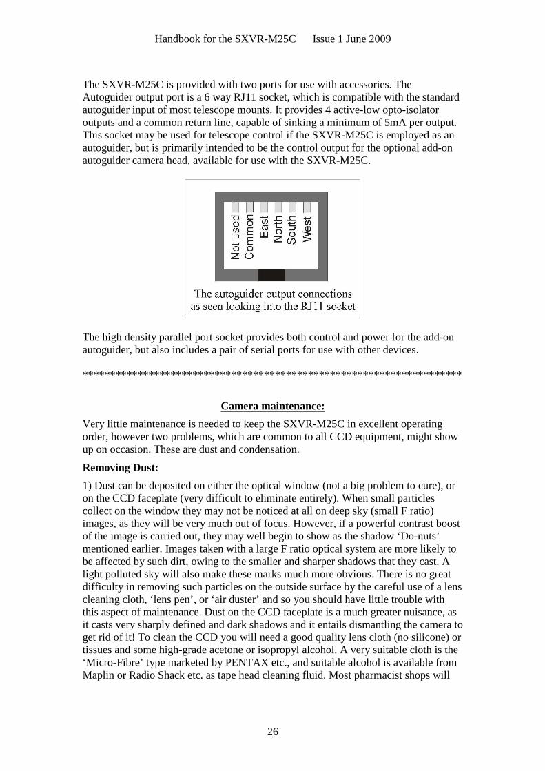
The SXVR-M25C is provided with two ports for use with accessories. TheAutoguider output port is a 6 way RJ11 socket, which is compatible with the standardautoguider input of most telescope mounts. It provides 4 active-low opto-isolatoroutputs and a common return line, capable of sinking a minimum of 5mA per output.This socket may be used for telescope control if the SXVR-M25C is employed as anautoguider, but is primarily intended to be the control output for the optional add-onautoguider camera head, available for use with the SXVR-M25C.
The high density parallel port socket provides both control and power for the add-onautoguider, but also includes a pair of serial ports for use with other devices.
*********************************************************************
Camera maintenance:
Very little maintenance is needed to keep the SXVR-M25C in excellent operatingorder, however two problems, which are common to all CCD equipment, might showup on occasion. These are dust and condensation.
Removing Dust:
1) Dust can be deposited on either the optical window (not a big problem to cure), oron the CCD faceplate (very difficult to eliminate entirely). When small particlescollect on the window they may not be noticed at all on deep sky (small F ratio)images, as they will be very much out of focus. However, if a powerful contrast boostof the image is carried out, they may well begin to show as the shadow ‘Do-nuts’mentioned earlier. Images taken with a large F ratio optical system are more likely tobe affected by such dirt, owing to the smaller and sharper shadows that they cast. Alight polluted sky will also make these marks much more obvious. There is no greatdifficulty in removing such particles on the outside surface by the careful use of a lenscleaning cloth, ‘lens pen’, or ‘air duster’ and so you should have little trouble withthis aspect of maintenance. Dust on the CCD faceplate is a much greater nuisance, asit casts very sharply defined and dark shadows and it entails dismantling the camera toget rid of it! To clean the CCD you will need a good quality lens cloth (no silicone) ortissues and some high-grade acetone or isopropyl alcohol. A very suitable cloth is the‘Micro-Fibre’ type marketed by PENTAX etc., and suitable alcohol is available fromMaplin or Radio Shack etc. as tape head cleaning fluid. Most pharmacist shops will

Handbook for the SXVR-M25C Issue 1 June 2009
27
have small bottles of pure acetone. A bright light and a strong watchmakers eyeglasswill also be found to be essential.
Procedure:
1) Disconnect the lead from the camera head and remove it from the telescope. Placeit on a table with the optical window facing downward.
2) Remove the two M3 screws and the M8 nut from the camera back plate and easethe plate out of the camera body. Unplug the fan lead from the camera PCB.
3) Withdraw the body cylinder and unscrew the two top spacer pillars from the PCB.Now gently lift the PCB off the 20 way connector NOTING THE ORIENTATIONOF THE BOARD for correct replacement later. Now remove the lower two spacersfrom the heat sink plate assembly.
4) The camera heat sink assembly can now be lifted away from the camera frontbarrel and the CCD will be exposed. Note that a layer of white heat-sink compound isapplied to the periphery of the heat sink disc and this should be left undisturbed bysubsequent operations.
5) You can now closely examine the CCD faceplate under the spotlight using thewatchmaker's glass when any dust motes will show clearly. If there is only an oddparticle or two and the CCD is otherwise clean, carefully brush away the dust with acorner of your lens cloth. A smeared or very dusty CCD will need a few drops ofalcohol to clean thoroughly and you may have to make several attempts before thesurface is free of contamination. One gentle wipe from one end to the other, with noreturn stroke, will be found to be the most effective action. DO NOT rub vigorouslyand be very careful to avoid scratching the window.
6) Before re-assembly, make certain that the inside surface of the front window is alsoclean, and then carefully replace the camera front barrel and screw it into place. (If theheat sink seal is disturbed, renew it with fresh compound before reassembling).
7) Replace all the camera parts in reverse order and the job is done.
Dealing with condensation:
The SXVR-M25C is designed to avoid condensation by minimising the volume of airtrapped within the CCD cavity and by preventing moisture ingress. This normallyworks very well, but storage of the camera in a humid location can lead to the trappedair becoming moist by diffusion through the optical window mounting thread etc. andcan result in condensation on the CCD window. If this becomes a problem, try storingthe camera in a warm, dry place, or in a plastic lunch box containing a sachet of silicagel desiccant. If this is not effective, try opening the main barrel and loosening thestand-offs to allow a gap to form between the heat sink and the front barrel assembly.Now put the camera into a desiccator box (as above) or leave it in a warm place forseveral hours before re-sealing it.
N.B. DO NOT leave the camera switched on for long periods between uses. Thecold CCD will collect ice by slow diffusion through any small leaks and this willbecome corrosive water on the cooler and CCD pins when the power is removed. Ifsubstantial amounts of moisture are seen, dismantle the camera and dry itthoroughly.
Handbook for the SXVR-M25C Issue 1 June 2009
28
*********************************************************************
Alternative Software
Although we hope that you will be satisfied with our ‘SXV_hmf_usb’ software, othercompanies are offering alternative programs with more powerful processingfunctions. One of these is programs is ‘AstroArt’ by MSB software. You can purchaseAstroArt from many dealers Worldwide and more information may be obtained fromtheir web site at http://www.msb-astroart.com
‘Maxim DL’ is another popular choice and you can find out more by visitinghttp://www.cyanogen.com
*********************************************************************
Some details of the camera and CCD characteristics
CCD type: Sony ICX453AK Exview interline Bayer matrix imager.
CCD size: Active area 23.4mm x 14.9mm
CCD pixels: 3032 x 2016 pixel array. Each pixel is 7.4 x 7.4uM
Well depth: Full res. mode 30,000e. Binned 2x2 mode approx. 40,000e
Mean visual QE: 60%, 65% at peak (540nM)
Useful spectral response: 360nM – 1100nM
Readout noise: Approx. 5e RMS typical, 8e max.
Back focal distance: The CCD is approximately 17.5mm from the barrel front.
Camera size: 63mm diameter x 62mm long

Handbook for the SXVR-M25C Issue 1 June 2009
29
Dear Observer,
Thank you for purchasing a Starlight Xpress CCD Imaging System. We are confident that you will gainmuch satisfaction from this equipment, but please read carefully the accompanying instruction manualto ensure that you achieve the best performance that is capable of providing.
As with most sophisticated equipment a certain amount of routine maintenance is necessary to keep theequipment operating at its optimum performance. The maintenance has been kept to a minimum, and isfully described in the manual.
In the unfortunate instance when the equipment does not perform as expected might we recommendthat you first study the fault finding information supplied. If this does not remedy the problem, thencontact Starlight Xpress for further advice. Our message board service on the Starlight Xpress web sitewill often provide solutions to any problems.
The equipment is covered by a 12-month guarantee covering faulty design, material or workmanship inaddition to any statutory Consumer Rights of Purchasers.
CONDITIONS OF GUARANTEE
1) The equipment shall only be used for normal purposes described in the standard operatinginstructions, and within the relevant safety standards of the country where the equipment is used.
2) Repairs under guarantee will be free of charge providing proof of purchase is produced, and that theequipment is returned to the Service Agent at the Purchaser’s expense and risk, and that the equipmentproves to be defective.
3) The guarantee shall not apply to equipment damaged by fire, accident, wear an tear, misuse,unauthorised repairs, or modified in any way whatsoever, or damage suffered in transit to or from thePurchaser.
4) The Purchaser’s sole and exclusive rights under this guarantee is for repair, or at our discretion thereplacement of the equipment or any part thereof, and no remedy to consequential loss or damagewhatsoever.
5) This guarantee shall not apply to components that have a naturally limited life.
6) Starlight Xpress’s decision in all matters is final, and any faulty component which has been replacedwill become the property of Starlight Xpress Ltd.
For further info. or advice, please call:
Mr Michael Hattey,
Starlight Xpress Ltd.,
The Offices, Foxley Green Farm,
Ascot Road, Holyport,
Berkshire,
England. SL6 3LA
Tel: 01628 777126
Fax: 01628 580411
Email: [email protected]
Web site: http://www.starlight-xpress.co.uk