Embed Size (px)
Citation preview

Switching, protection, communication – the new NZM circuit-breaker series up to 1600 A
Think future. Switch to green.
A
http://nzm.moeller.net
Product InformationNZM circuit-breakers
NZM circuit-breaker
IZM circuit-breaker
Switchboard systems
Reliably and safely controlling,switching and managing power. In industry, in buildingsand in machine construction.Innovative protection concepts.With built-in diagnostics andcommunication functions.Housed in modern switchboardsystems.
For Immediate Delivery call KMParts.com at (866) 595-9616

3-pole circuit-breaker
4-pole circuit-breaker
“Moeller simply has the experience.This is evident with every singleproduct, with the service you receiveand the people.”
The new range up to 1600 A – New ideas for better circuit-breakers
2
The new Moeller circuit-breakers covera range from 15 to 1600 A with justfour frame sizes. And they are optimallymatched to one another. The wideapplication spectrum covers everyrequirement as Moeller has closely exa-mined what every customer needs andimplemented the appropriate solutions.Outstanding, for example, is the contin-uous switching power range – whichextends from the smallest to the largestcircuit-breaker or the modular systemwhich can be matched without difficultyto suit the specific application. Thus, thecircuit-breakers can be used universally– from the smallest of service distributionboards, to machine controls or motorstarter combinations, up to large energydistribution systems with a short-circuitbreaking capacity of up to 150 kA.
For Immediate Delivery call KMParts.com at (866) 595-9616
3
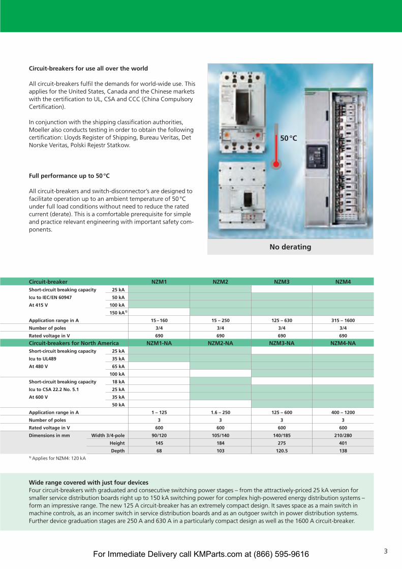
Circuit-breakers for use all over the world
All circuit-breakers fulfil the demands for world-wide use. Thisapplies for the United States, Canada and the Chinese marketswith the certification to UL, CSA and CCC (China CompulsoryCertification).
In conjunction with the shipping classification authorities,Moeller also conducts testing in order to obtain the followingcertification: Lloyds Register of Shipping, Bureau Veritas, DetNorske Veritas, Polski Rejestr Statkow.
Full performance up to 50 °C
All circuit-breakers and switch-disconnector’s are designed tofacilitate operation up to an ambient temperature of 50 °Cunder full load conditions without need to reduce the ratedcurrent (derate). This is a comfortable prerequisite for simpleand practice relevant engineering with important safety com-ponents.
No derating
50°C
Wide range covered with just four devicesFour circuit-breakers with graduated and consecutive switching power stages – from the attractively-priced 25 kA version forsmaller service distribution boards right up to 150 kA switching power for complex high-powered energy distribution systems –form an impressive range. The new 125 A circuit-breaker has an extremely compact design. It saves space as a main switch inmachine controls, as an incomer switch in service distribution boards and as an outgoer switch in power distribution systems.Further device graduation stages are 250 A and 630 A in a particularly compact design as well as the 1600 A circuit-breaker.
Circuit-breaker NZM1 NZM2 NZM3 NZM4Short-circuit breaking capacity 25 kA
Icu to IEC/EN 60947 50 kA
At 415 V 100 kA
150 kA1)
Application range in A 15–160 15 – 250 125 – 630 315 – 1600
Number of poles 3/4 3/4 3/4 3/4
Rated voltage in V 690 690 690 690
Circuit-breakers for North America NZM1-NA NZM2-NA NZM3-NA NZM4-NAShort-circuit breaking capacity 25 kA
Icu to UL489 35 kA
At 480 V 65 kA
100 kA
Short-circuit breaking capacity 18 kA
Icu to CSA 22.2 No. 5.1 25 kA
At 600 V 35 kA
50 kA
Application range in A 1 – 125 1.6 – 250 125 – 600 400 – 1200
Number of poles 3 3 3 3
Rated voltage in V 600 600 600 600
Dimensions in mm Width 3/4-pole 90/120 105/140 140/185 210/280
Height 145 184 275 401
Depth 68 103 120.5 1381) Applies for NZM4: 120 kA
For Immediate Delivery call KMParts.com at (866) 595-9616
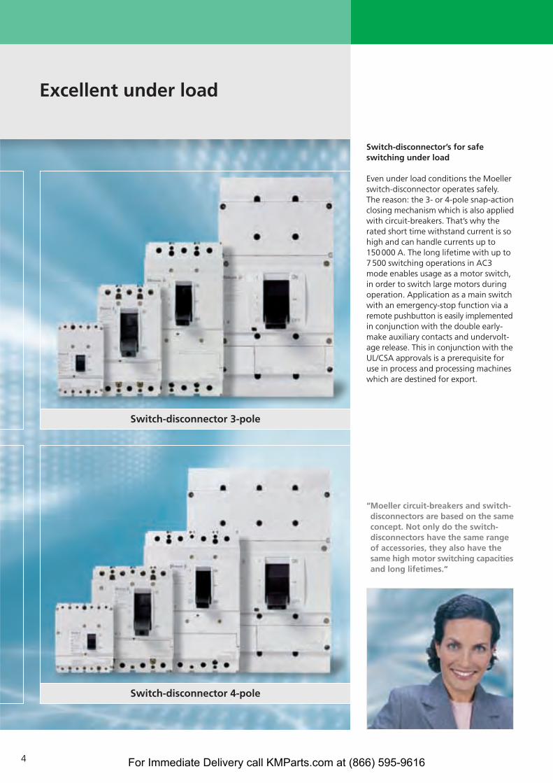
Excellent under load
4
Switch-disconnector 3-pole
Switch-disconnector 4-pole
“Moeller circuit-breakers and switch-disconnectors are based on the sameconcept. Not only do the switch-disconnectors have the same rangeof accessories, they also have thesame high motor switching capacitiesand long lifetimes.“
Switch-disconnector’s for safeswitching under load
Even under load conditions the Moellerswitch-disconnector operates safely.The reason: the 3- or 4-pole snap-actionclosing mechanism which is also appliedwith circuit-breakers. That’s why therated short time withstand current is sohigh and can handle currents up to150 000 A. The long lifetime with up to7 500 switching operations in AC3mode enables usage as a motor switch,in order to switch large motors duringoperation. Application as a main switchwith an emergency-stop function via aremote pushbutton is easily implementedin conjunction with the double early-make auxiliary contacts and undervolt-age release. This in conjunction with theUL/CSA approvals is a prerequisite foruse in process and processing machineswhich are destined for export.
For Immediate Delivery call KMParts.com at (866) 595-9616
5
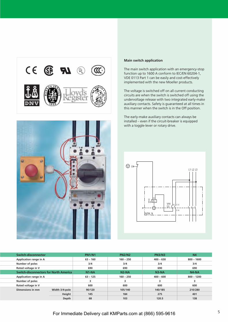
Main switch application
The main switch application with an emergency-stopfunction up to 1600 A conform to IEC/EN 60204-1,VDE 0113 Part 1 can be easily and cost-effectivelyimplemented with the new Moeller products.
The voltage is switched off on all current conductingcircuits are when the switch is switched off using theundervoltage release with two integrated early-makeauxiliary contacts. Safety is guaranteed at all times inthis manner when the switch is in the Off position.
The early-make auxiliary contacts can always beinstalled – even if the circuit-breaker is equipped with a toggle-lever or rotary drive.
Switch-disconnector PN1/N1 PN2/N2 PN3/N3 N4Application range in A 63 – 160 160 – 250 400 – 630 800 – 1600
Number of poles 3/4 3/4 3/4 3/4
Rated voltage in V 690 690 690 690
Switch-disconnectors for North America N1-NA N2-NA N3-NA N4-NAApplication range in A 63 – 125 160 – 250 400 – 600 800 – 1200
Number of poles 3 3 3 3
Rated voltage in V 600 600 600 600
Dimensions in mm Width 3/4-pole 90/120 105/140 140/185 210/280
Height 145 184 275 401
Depth 68 103 120.5 138
For Immediate Delivery call KMParts.com at (866) 595-9616
1
2
3
4
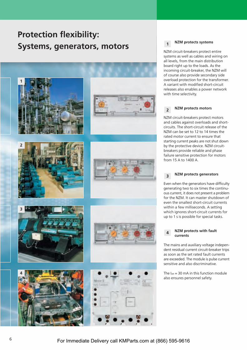
Protection flexibility:Systems, generators, motors
6
NZM protects systems
NZM circuit-breakers protect entiresystems as well as cables and wiring onall levels, from the main distributionboard right up to the loads. As theincoming circuit-breaker, the NZM willof course also provide secondary sideoverload protection for the transformer.A variant with modified short-circuitreleases also enables a power networkwith time selectivity.
NZM protects motors
NZM circuit-breakers protect motorsand cables against overloads and short-circuits. The short-circuit release of theNZM can be set to 12 to 14 times therated motor current to ensure thatstarting current peaks are not shut downby the protective device. NZM circuit-breakers provide reliable and phase failure sensitive protection for motorsfrom 15 A to 1400 A.
NZM protects generators
Even when the generators have difficultygenerating two to six times the continu-ous current, it does not present a problemfor the NZM. It can master shutdown ofeven the smallest short-circuit currentswithin a few milliseconds. A settingwhich ignores short-circuit currents forup to 1 s is possible for special tasks.
NZM protects with faultcurrents
The mains and auxiliary voltage indepen-dent residual current circuit-breaker tripsas soon as the set rated fault currentsare exceeded. The module is pulse currentsensitive and also discriminative.
The I∆N = 30 mA in this function modulealso ensures personnel safety.
4
3
2
1
For Immediate Delivery call KMParts.com at (866) 595-9616

7
Selectivity table
NZM circuit-breakers achieve selectivityduring a short-circuit even withoutadditional electronic short-time delayeddevices. For example, the 1000 A circuit-breaker in combination with a 250 Aoutgoing circuit-breaker is fully selectiveup to a maximum existing short-circuitcurrent of 100 000 A. Even two highenergy incoming supplies of e.g. twoparallel 2 000 kVA distribution transfor-mers are cost-effective and are simpleto engineer with high levels of supplyreliability.
Trip electronics featuring micro-processors enhance the operatingcontinuity
The microprocessor controlled digitalelectronics determine r.m.s. values for the load current to be monitored. In contrast to analog electronics, anyharmonics which may be in the powergrid will be correctly evaluated and donot cause premature and unexpectedtrips. This prevents a standstill.
Special components simulate a thermalmemory even when the switch tripsduring a currentless period due to a
load overload. Thus, safe protection ofthe connected equipment is guaranteed– even when the device is switchedback on after a brief cooling off phase.
All electronics have been routinely tested and preaged in an oven. This corresponds to a real operating time of about six months. Thermocouplesguarantee a safety-oriented trip of thecircuit-breaker in the improbable casethat an inadmissible overtemperature is due to the electronic components.
Simpler visualisation, comparison and documentation of characteristic curves
The free-of-charge characteristic curve program supportsdocumentation of the circuit-breakers which are used incompleted switchgear systems. All setting parameters canbe easily determined, graphically displayed and printed-out.A direct comparison of NZM circuit-breaker and IZM circuit-breaker in combination with h.b.c. fuses enables assessmentof the selectivity for the overload and time-delayed over-current range.
NZM4
NZM2
100 kA 80 kA
PKZM0
NZM3
NZM1
100 kA
10 A 160 A
25 kA
630 A250 A
1600 A
Tripping graphs
Trip
pin
g t
ime
Current [Amps]
General specifications:Company: Moeller GmbH
Installation: Energy distributionEditor: John Public
Date: 17.3.2004Line: 415 V/50 cps
For Immediate Delivery call KMParts.com at (866) 595-9616
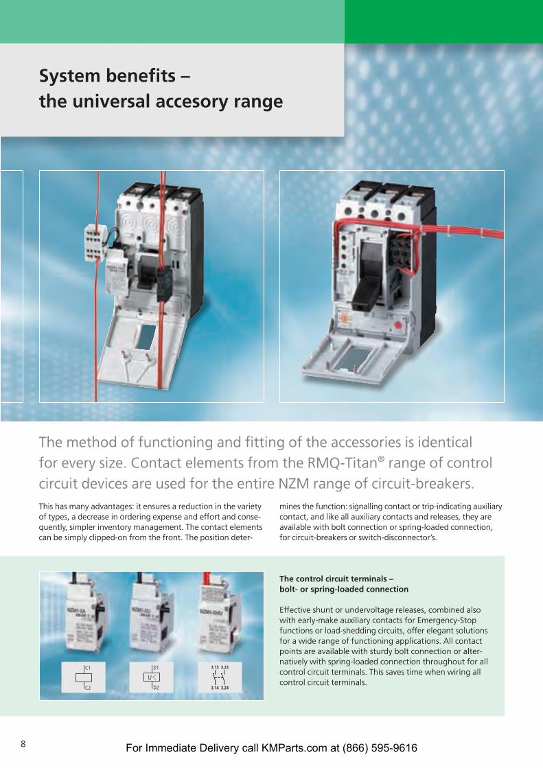
This has many advantages: it ensures a reduction in the varietyof types, a decrease in ordering expense and effort and conse-quently, simpler inventory management. The contact elementscan be simply clipped-on from the front. The position deter-
mines the function: signalling contact or trip-indicating auxiliarycontact, and like all auxiliary contacts and releases, they areavailable with bolt connection or spring-loaded connection,for circuit-breakers or switch-disconnector’s.
The control circuit terminals – bolt- or spring-loaded connection
Effective shunt or undervoltage releases, combined alsowith early-make auxiliary contacts for Emergency-Stopfunctions or load-shedding circuits, offer elegant solutionsfor a wide range of functioning applications. All contactpoints are available with sturdy bolt connection or alter-natively with spring-loaded connection throughout for allcontrol circuit terminals. This saves time when wiring allcontrol circuit terminals.
The method of functioning and fitting of the accessories is identical for every size. Contact elements from the RMQ-Titan® range of controlcircuit devices are used for the entire NZM range of circuit-breakers.
System benefits – the universal accesory range
8 For Immediate Delivery call KMParts.com at (866) 595-9616

9
All messages in detail – the Data Management Interface
It does not matter if the causes for atrip or a warning message with unbal-ance are required, or if all phase currentsare to be displayed directly on-site andcorrective actions are to be implementedwith a critical load state. The Data Management Interface (DMI) alwayssignals exact details. The relay outputsof the DMI signal up to 6 differentmessages. All trip causes are availableas group signals and Ii, Ir, Isd, I2t, and Idn
detail signals. The trip cause, phasestate, switch setting as well as date andtime can be accessed via the 4-line display. Representation of the actualphase currents can be in absolute orrelative (% Ir) terms. Warnings withregard to the load status are issued at70 %, 100 % and 120 % Ir. Thus, the DMI is perfect for direct display on-siteor for the integration in higher-levelenergy management concepts.
Spring-loaded terminations – handling of the entire range with a single action
Moeller provides spring-loaded termi-nals universally for all control-lineterminations. On contactors and motor-protective circuit-breakers they arealso provided on the main circuit up to a rating of 16 A.
>100% Ir Trip Isd
Unbalance
For Immediate Delivery call KMParts.com at (866) 595-9616

Variable operation – toggle, turn, automatic operation
10
The door coupling rotary handle –for uniform, flexible solutions
The base plate is the same for everydoor coupling rotary handle, this meansfaster fitting due to the identical drillingdiagram. The switches can also be fittedvertically or horizontally in the controlpanel.
Door coupling rotary handles – ergonomic switching
Four different shaft lengths enabledevice installation in various controlpanels and housings up to a depth of 600 mm. A cost-effective and simpleto mounting solution is available forthe narrowest component mountingwhere the switch makes direct contactwith the cover.
“Circuit-breakers and switch-discon-nectors from Moeller impress mebecause of their wider range ofinstallation and operating features.“
For Immediate Delivery call KMParts.com at (866) 595-9616
11
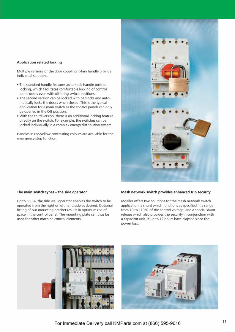
Application related locking
Multiple versions of the door coupling rotary handle provideindividual solutions.
• The standard handle features automatic handle positionlocking, which facilitates comfortable locking of control panel doors even with differing switch positions.
• The second version can be locked with padlocks and auto-matically locks the doors when closed. This is the typicalapplication for a main switch as the control panels can onlybe opened in the Off position.
• With the third version, there is an additional locking featuredirectly on the switch. For example, the switches can belocked individually in a complex energy distribution system.
Handles in red/yellow contrasting colours are available for theemergency-stop function.
The main switch types – the side operator
Up to 630 A, the side wall operator enables the switch to beoperated from the right or left hand side as desired. Optionalfitting of our mounting bracket results in optimum use ofspace in the control panel. The mounting plate can thus beused for other machine control elements.
Mesh network switch provides enhanced trip security
Moeller offers two solutions for the mesh network switchapplication: a shunt which functions as specified in a rangefrom 10 to 110 % of the control voltage, and a special shuntrelease which also provides trip security in conjunction with a capacitor unit, if up to 12 hours have elapsed since the power loss.
For Immediate Delivery call KMParts.com at (866) 595-9616

21
22
13
14
Safe to operate, easy to handle
12
The remote operators – simple, uniform operation
The concept of uniform functionsbrings about simpler operation for allremote operators. The spring-poweredactuator permits closing delays of 60 or 100 ms, thereby also allowing appli-cation in the field of synchronization.Short function sequences and fewerparts ensure a high degree of stabilityand a long service life. Safety is alsoemphasized here by the sealing optionfor the Auto function and by the facilityfor padlocking the remote operator.
The withdrawable unit – signalling of states
As usual, Moeller offers plug-in andwithdrawable units in addition to thefixed mounted option. It makes it easier to quickly adapt to malfunctionsor increases in the rated current rangeand thus avoid long downtimes. Uniform racking handle operation forwithdrawable units enhances operatingsafety and ensures a test position forfunction testing without having toswitch the main contacts.
The “Inserted“, “Test“ and “Retracted“positions can be remotely signalledusing RMQ auxiliary switch contacts.
The plug-in unit – open to possibilities
The plug-in feature enables rapid anduncomplicated exchange of circuit-breakers without having to shutdownthe entire system. The same widths forthe fixed and withdrawable circuit-breakers ensure simple engineeringduring the system design phase.
A very visible isolating distance can beimplemented in addition to the isolatingcharacteristics by the use of plug-inbreakers. The open plug-in contacts arefinger-proof (IP2X).
If the system is to be modified at a laterdate, the use of plug-in sockets forreserve outgoers is recommended.
For Immediate Delivery call KMParts.com at (866) 595-9616
13
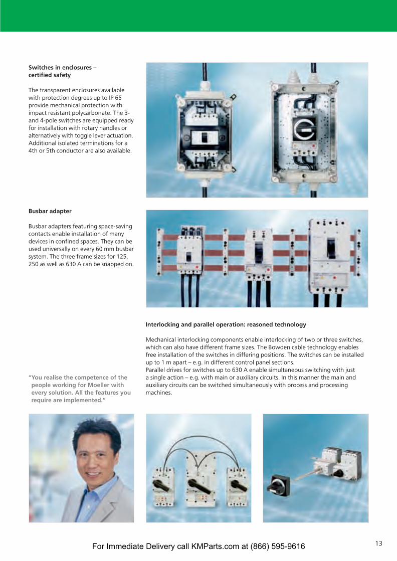
Switches in enclosures – certified safety
The transparent enclosures availablewith protection degrees up to IP 65 provide mechanical protection withimpact resistant polycarbonate. The 3-and 4-pole switches are equipped readyfor installation with rotary handles oralternatively with toggle lever actuation.Additional isolated terminations for a4th or 5th conductor are also available.
Busbar adapter
Busbar adapters featuring space-savingcontacts enable installation of manydevices in confined spaces. They can beused universally on every 60 mm busbarsystem. The three frame sizes for 125,250 as well as 630 A can be snapped on.
“You realise the competence of thepeople working for Moeller withevery solution. All the features yourequire are implemented.“
Interlocking and parallel operation: reasoned technology
Mechanical interlocking components enable interlocking of two or three switches,which can also have different frame sizes. The Bowden cable technology enablesfree installation of the switches in differing positions. The switches can be installedup to 1 m apart – e.g. in different control panel sections.Parallel drives for switches up to 630 A enable simultaneous switching with just a single action – e.g. with main or auxiliary circuits. In this manner the main andauxiliary circuits can be switched simultaneously with process and processingmachines.
For Immediate Delivery call KMParts.com at (866) 595-9616

Clever mounting and connectionincreases economy
14
Easy to connect
NZM circuit-breakers and PN, N switchdisconnectors can be connected withand without cable lugs, braided copperbands or copper busbars. And there’sanother special feature: Special narrowcable lug versions are available for boltconnection of round conductors up to240 mm.
Screw terminal
The screw terminal is the most attracti-vely priced solution for the connectionof cable-lugs, flat drilled metal strip orcopper busbars.
Box terminal for copper cable
Box terminals guarantee secure contactfor the direct connection of 1 – 2 flexiblecopper conductors or flat strip. WithNZM2 and NZM3, the top of the box ter-minal can be opened for easy insertion.
3
2
1 Terminal for aluminium and copper cables
The terminal area of these special ter-minals is tunnel-shaped to prevent thetypical “flow-properties” of aluminiumunder great pressing power. Up to fourcopper or aluminium conductors can be connected depending on the type.
Connection preparation for multiple conductors
It enables the connection of up to sixconductors with cable lugs per phase.Auxiliary busbars are no longerrequired.
Rear connection
This method of connection allows busbars or round conductors to be connected at the rear. Partitioning ofthe switch area, terminal area andoperator area is carried out without difficulty.
6
5
4
1
4
2
5
3
6
Control circuit terminals
The control circuit terminals are simply screwed onto the respectiveconnection type. The tap-offs forvoltage meters, control transformersand undervoltage releases are imple-mented quickly.
Back of hand or finger-proof
Cable-lug, box-terminal or tunnelterminal, it does not matter as coverswill always ensure that they areback-of-hand proof.
Fingerproof to IP2X, conform toIEC/EN 60204-1 for main switches isfast and easy to implement. The newadditional covers can be matched toevery cross-section.
2
1
1
2
For Immediate Delivery call KMParts.com at (866) 595-9616
15
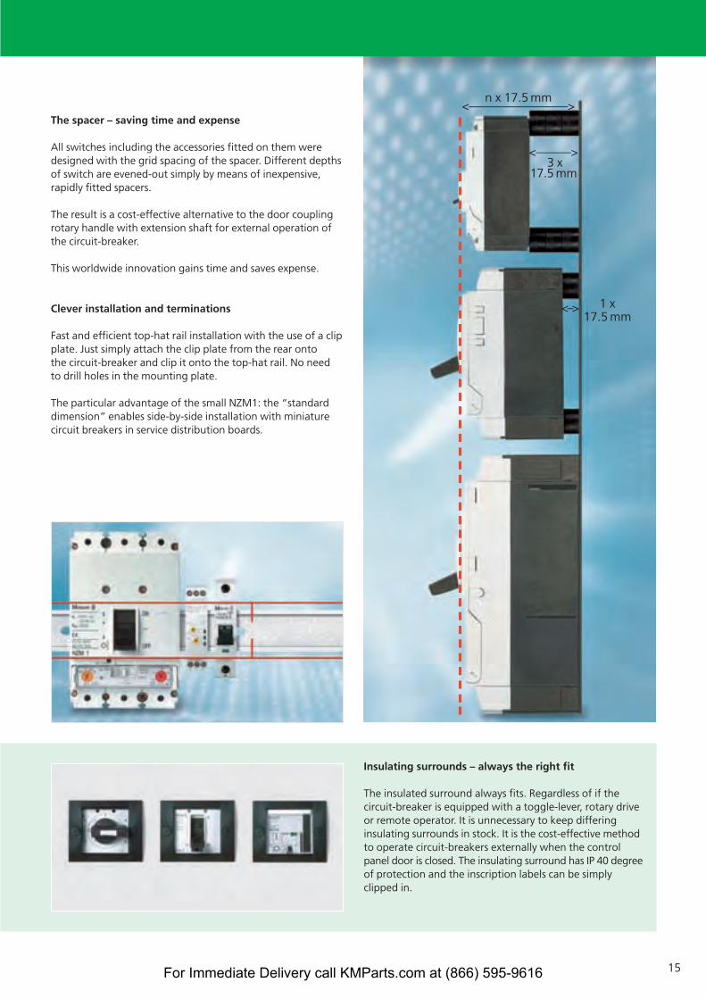
The spacer – saving time and expense
All switches including the accessories fitted on them weredesigned with the grid spacing of the spacer. Different depthsof switch are evened-out simply by means of inexpensive,rapidly fitted spacers.
The result is a cost-effective alternative to the door couplingrotary handle with extension shaft for external operation ofthe circuit-breaker.
This worldwide innovation gains time and saves expense.
Clever installation and terminations
Fast and efficient top-hat rail installation with the use of a clipplate. Just simply attach the clip plate from the rear onto the circuit-breaker and clip it onto the top-hat rail. No need to drill holes in the mounting plate.
The particular advantage of the small NZM1: the “standarddimension” enables side-by-side installation with miniaturecircuit breakers in service distribution boards.
n x 17.5 mm<–––––––––––––––––>
<––––––>3 x
17.5 mm
1 x 17.5 mm
<–>
Insulating surrounds – always the right fit
The insulated surround always fits. Regardless of if thecircuit-breaker is equipped with a toggle-lever, rotary driveor remote operator. It is unnecessary to keep differinginsulating surrounds in stock. It is the cost-effective methodto operate circuit-breakers externally when the controlpanel door is closed. The insulating surround has IP 40 degreeof protection and the inscription labels can be simplyclipped in.
For Immediate Delivery call KMParts.com at (866) 595-9616

4
3
2
1
PROCESS FIELD BUS
Diagnostics included! From contact to control system
16
The NZM electronic circuit-breaker offers a comprehensive range of on-board diagnostic functions for all versions. All important informationcan be recorded, displayed on-site and passed onto higher level systems.
System transparency is enhanced and the reaction times tocritical states, e.g. over current, phase unbalance or phasefailure can be reduced. Detailed event protocols enable quickdiagnosis of fault causes. Operating time and switchingoperation counters facilitate planning of preventative mainte-
nance activities. Protocol functions support the documentationof status, diagnostic messages and parameter setting. Themodularity guarantees the necessary level of flexibility withexpansion and retrofitting to react to changing demands.
For Immediate Delivery call KMParts.com at (866) 595-9616
17
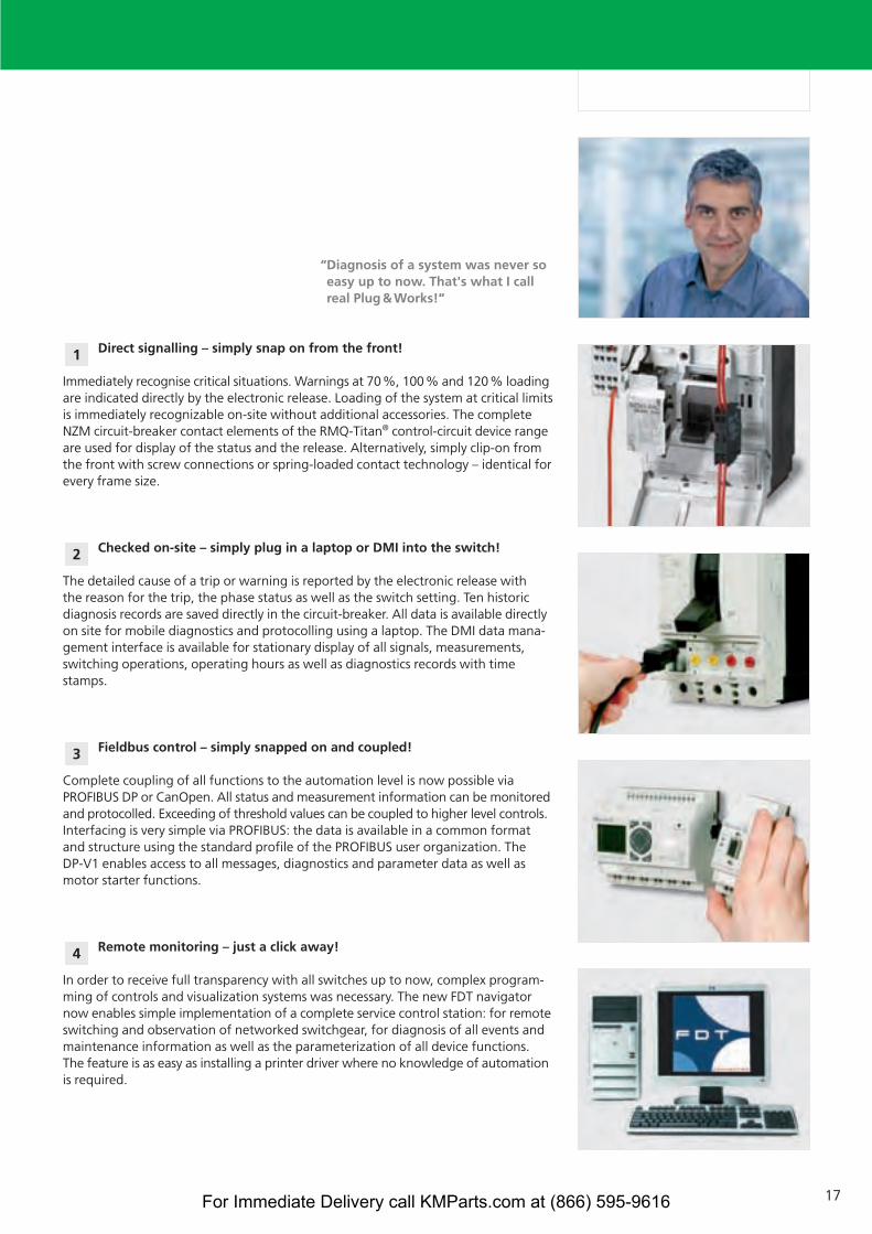
“Diagnosis of a system was never soeasy up to now. That's what I callreal Plug&Works!“
Direct signalling – simply snap on from the front!
Immediately recognise critical situations. Warnings at 70%, 100% and 120% loadingare indicated directly by the electronic release. Loading of the system at critical limitsis immediately recognizable on-site without additional accessories. The completeNZM circuit-breaker contact elements of the RMQ-Titan® control-circuit device rangeare used for display of the status and the release. Alternatively, simply clip-on fromthe front with screw connections or spring-loaded contact technology – identical forevery frame size.
Checked on-site – simply plug in a laptop or DMI into the switch!
The detailed cause of a trip or warning is reported by the electronic release with the reason for the trip, the phase status as well as the switch setting. Ten historicdiagnosis records are saved directly in the circuit-breaker. All data is available directlyon site for mobile diagnostics and protocolling using a laptop. The DMI data mana-gement interface is available for stationary display of all signals, measurements,switching operations, operating hours as well as diagnostics records with timestamps.
Fieldbus control – simply snapped on and coupled!
Complete coupling of all functions to the automation level is now possible viaPROFIBUS DP or CanOpen. All status and measurement information can be monitoredand protocolled. Exceeding of threshold values can be coupled to higher level controls.Interfacing is very simple via PROFIBUS: the data is available in a common formatand structure using the standard profile of the PROFIBUS user organization. The DP-V1 enables access to all messages, diagnostics and parameter data as well asmotor starter functions.
Remote monitoring – just a click away!
In order to receive full transparency with all switches up to now, complex program-ming of controls and visualization systems was necessary. The new FDT navigatornow enables simple implementation of a complete service control station: for remoteswitching and observation of networked switchgear, for diagnosis of all events andmaintenance information as well as the parameterization of all device functions.The feature is as easy as installing a printer driver where no knowledge of automationis required.
4
3
2
1
For Immediate Delivery call KMParts.com at (866) 595-9616
18
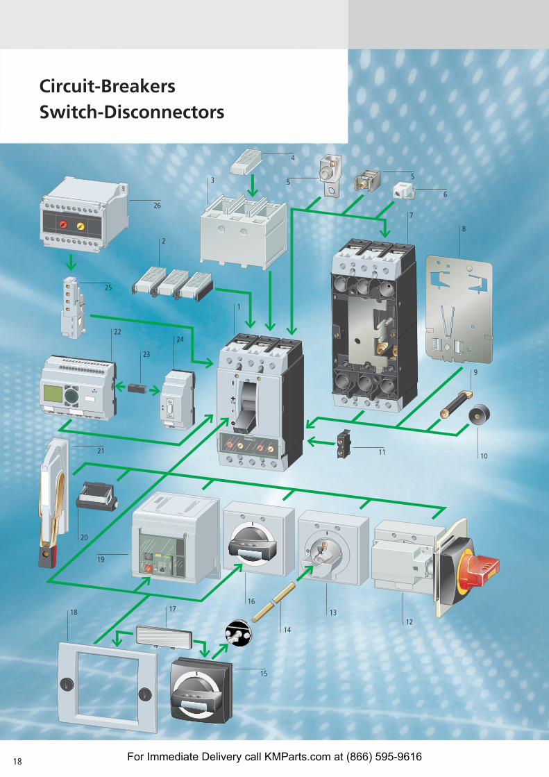
Circuit-BreakersSwitch-Disconnectors
15
11
5
6
5
4
25
21
26
12
10
9
16
14
18 17 13
20
7
8
2224
23
1
3
2
19
For Immediate Delivery call KMParts.com at (866) 595-9616

19
Circuit-breakers, Switch-disconnectors
Circuit-breakers, switch-disconnectors 1
IP2X finger proof 2For box terminals
Connection shroud 3Protection against direct contact with connection of cable lugs, busbarsor when tunnel terminals are used
IP2X finger proof 4For cover
Tunnel terminals for Al and Cu cables 5Standard with control circuit terminal
Box terminals 5Standard feature of frame size 1Mounting within the switch enclosure
Control circuit terminal 6For two connection positions top or bottom
Plug-in and withdrawable unit 7
Clip plate 8
Rear side connection 9
Spacer 10
Standard auxiliary contact 11Switches with the main contacts.Performs signalling and interlock tasks
Trip-indicating auxiliary contact 11General trip indication with trip dueto overload or short-circuit as well asvoltage release
Main switch rotary handle 12for side panel mounting
Door coupling rotary handle 13, 15• lockable• with door interlock
Extension shaft 14Can be cut to required length
Rotary handle 16• lockable
External warning/designation label 17
Insulating surround 18For use on the enclosure with lead through toggle lever, rotary drive and remote operator
Remote operator 19For switch on/off and reset by permanent or three-wire control
Toggle level locking device 20
Side lever handle 21In preparation
Data Management Interface (DMI Module) 22Access to diagnostics and operational dataDetection of current values Parameterisation and control of the circuit-breaker with electronic releases
EASY-LINK-DS data plug 23
PROFIBUS-DP interface 24
Early-make auxiliary contact 25For interlock and load shedding circuits as well as for early-make switching of theundervoltage release with main switch/Emergency-Stop applications
Voltage release 25Undervoltage release• non-delayed• off-delayedShunt release
Time delay unit for 26undervoltage releases
Switch-disconnectors
With main switch characteristics to IEC/EN 60204 and isolating characteristics to IEC/EN 60947, VDE 0660 without overload and short-circuit release
Rated uninterrupted current Iu = rated current In 63 – 160 160 – 250 400 – 630 800 – 1600Type N triggering with U/A voltage release PN1-... N1-... PN2-... N2-... PN3-... N3-... N4-...Rated short-circuit making capacity Icm kA 2.8 2. 5.5 5.5 25 25 53Rated short-time withstand current Icw (1s currentrms) kA 2 2 3.5 3.5 12.5 12.5 25With main switch and isolating characteristicswithout overload and short-circuit release
UL/CSA approved conform to UL 489, CSA 5 as well as IEC 60947
Rated uninterrupted current Iu = rated current In 63 – 125 160 – 250 400 – 600 800 – 1200N1-...-NA N2-...-NA N3-...-NA N4-...-NA
Rated short-circuit making capacity Icm kA 2.8 5.5 25 53Rated short-time withstand current Icw (1s currentrms) kA 2 3.5 12.5 25
For Immediate Delivery call KMParts.com at (866) 595-9616
20
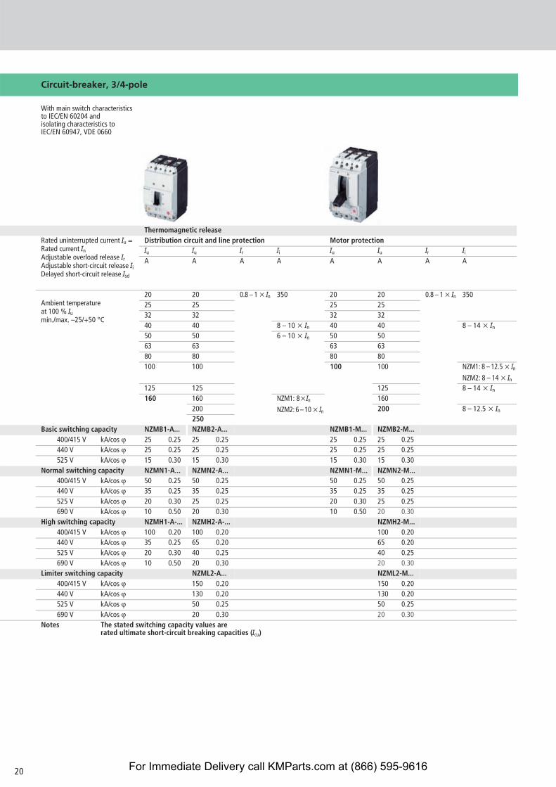
Circuit-breaker, 3/4-pole
With main switch characteristics to IEC/EN 60204 and isolating characteristics to IEC/EN 60947, VDE 0660
Thermomagnetic releaseRated uninterrupted current Iu = Rated current InAdjustable overload release IrAdjustable short-circuit release IiDelayed short-circuit release Isd
Distribution circuit and line protection Motor protectionIu Iu Ir Ii Iu Iu Ir Ii
A A A A A A A A
Ambient temperature at 100 % Iumin./max. –25/+50 °C
20 20 0.8 – 1 x In 350 20 20 0.8 – 1 x In 35025 25 25 2532 32 32 3240 40 8 – 10 x In 40 40 8 – 14 x In50 50 6 – 10 x In 50 5063 63 63 6380 80 80 80100 100 100 100 NZM1: 8 – 12.5 x In
NZM2: 8 – 14 x In125 125 125 8 – 14 x In160 160 NZM1: 8xIn
NZM2: 6 – 10 x In
160200 200 8 – 12.5 x In250
Basic switching capacity NZMB1-A... NZMB2-A... NZMB1-M... NZMB2-M...400/415 V kA/cos v 25 0.25 25 0.25 25 0.25 25 0.25440 V kA/cos v 25 0.25 25 0.25 25 0.25 25 0.25525 V kA/cos v 15 0.30 15 0.30 15 0.30 15 0.30
Normal switching capacity NZMN1-A... NZMN2-A... NZMN1-M... NZMN2-M...400/415 V kA/cos v 50 0.25 50 0.25 50 0.25 50 0.25440 V kA/cos v 35 0.25 35 0.25 35 0.25 35 0.25525 V kA/cos v 20 0.30 25 0.25 20 0.30 25 0.25690 V kA/cos v 10 0.50 20 0.30 10 0.50 20 0.30
High switching capacity NZMH1-A-... NZMH2-A-... NZMH2-M...400/415 V kA/cos v 100 0.20 100 0.20 100 0.20440 V kA/cos v 35 0.25 65 0.20 65 0.20525 V kA/cos v 20 0.30 40 0.25 40 0.25690 V kA/cos v 10 0.50 20 0.30 20 0.30
Limiter switching capacity NZML2-A... NZML2-M...400/415 V kA/cos v 150 0.20 150 0.20440 V kA/cos v 130 0.20 130 0.20525 V kA/cos v 50 0.25 50 0.25690 V kA/cos v 20 0.30 20 0.30
Notes The stated switching capacity values arerated ultimate short-circuit breaking capacities (Icu)
For Immediate Delivery call KMParts.com at (866) 595-9616
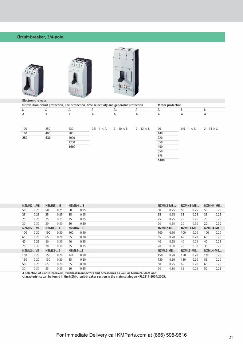
Circuit-breaker, 3/4-pole
Electronic releaseDistribution circuit protection, line protection, time selectivity and generator protection Motor protectionIu Iu Iu Ir Isd Ii Iu Ir Ii
A A A A A A A A A
100 250 630 0.5 – 1 x In 2 – 10 x Ir 2 – 12 x In 90 0.5 – 1 x In 2 – 14 x Ir160 400 800 140250 630 1000 220
1250 3501600 450
5508751400
NZMN2-...VE NZMN3-...E NZMN4-...E NZMN2-ME... NZMN3-ME... NZMN4-ME...50 0.25 50 0.25 50 0.25 50 0.25 50 0.25 50 0.2535 0.25 35 0.25 35 0.25 35 0.25 35 0.25 35 0.2525 0.25 25 0.25 25 0.25 25 0.25 25 0.25 25 0.2520 0.30 20 0.30 20 0.30 20 0.30 20 0.30 20 0.30NZMH2-...VE NZMH3-...E NZMH4-...E NZMH2-ME... NZMH3-ME... NZMH4-ME...100 0.20 100 0.20 100 0.20 100 0.20 100 0.20 100 0.2065 0.20 65 0.20 65 0.20 65 0.20 65 0.20 65 0.2040 0.25 40 0.25 40 0.25 40 0.25 40 0.25 40 0.2520 0.30 20 0.30 35 0.25 20 0.30 20 0.30 35 0.25NZML2-...VE NZML3-...E NZML4-...E NZML2-ME... NZML3-ME... NZML4-ME...150 0.20 150 0.20 120 0.20 150 0.20 150 0.20 120 0.20130 0.20 130 0.20 85 0.20 130 0.20 130 0.20 85 0.2050 0.25 65 0.20 65 0.20 50 0.25 65 0.20 65 0.2020 0.30 35 0.25 50 0.25 20 0.30 35 0.25 50 0.25A selection of circuit-breakers, switch-disconnectors and accessories as well as technical data and characteristics can be found in the NZM circuit-breaker section in the main catalogue HPL0211-2004/2005.
21For Immediate Delivery call KMParts.com at (866) 595-9616
22
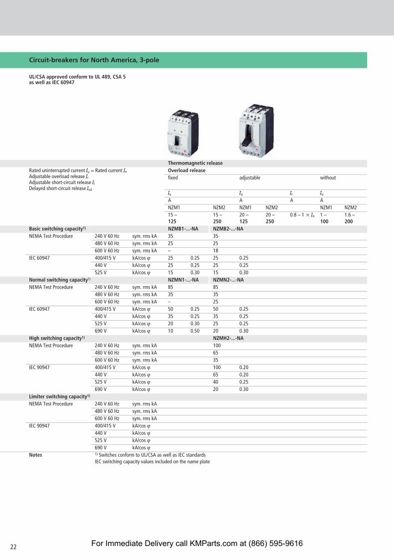
Circuit-breakers for North America, 3-pole
UL/CSA approved conform to UL 489, CSA 5 as well as IEC 60947
Thermomagnetic releaseRated uninterrupted current Iu = Rated current InAdjustable overload release IrAdjustable short-circuit release IiDelayed short-circuit release Isd
Overload releasefixed adjustable without
Iu Iu Ir Iu
A A A ANZM1 NZM2 NZM1 NZM2 NZM1 NZM215 – 125
15 – 250
20 – 125
20 – 250
0.8 – 1 x In 1 – 100
1.6 – 200
Basic switching capacity1) NZMB1-...-NA NZMB2-...-NANEMA Test Procedure 240 V 60 Hz sym. rms kA 35 35
480 V 60 Hz sym. rms kA 25 25600 V 60 Hz sym. rms kA – 18
IEC 60947 400/415 V kA/cos v 25 0.25 25 0.25440 V kA/cos v 25 0.25 25 0.25525 V kA/cos v 15 0.30 15 0.30
Normal switching capacity1) NZMN1-...-NA NZMN2-...-NANEMA Test Procedure 240 V 60 Hz sym. rms kA 85 85
480 V 60 Hz sym. rms kA 35 35600 V 60 Hz sym. rms kA – 25
IEC 60947 400/415 V kA/cos v 50 0.25 50 0.25440 V kA/cos v 35 0.25 35 0.25525 V kA/cos v 20 0.30 25 0.25690 V kA/cos v 10 0.50 20 0.30
High switching capacity1) NZMH2-...-NANEMA Test Procedure 240 V 60 Hz sym. rms kA 100
480 V 60 Hz sym. rms kA 65600 V 60 Hz sym. rms kA 35
IEC 90947 400/415 V kA/cos v 100 0.20440 V kA/cos v 65 0.20525 V kA/cos v 40 0.25690 V kA/cos v 20 0.30
Limiter switching capacity1)
NEMA Test Procedure 240 V 60 Hz sym. rms kA480 V 60 Hz sym. rms kA600 V 60 Hz sym. rms kA
IEC 90947 400/415 V kA/cos v440 V kA/cos v525 V kA/cos v690 V kA/cos v
Notes 1) Switches conform to UL/CSA as well as IEC standardsIEC switching capacity values included on the name plate
For Immediate Delivery call KMParts.com at (866) 595-9616
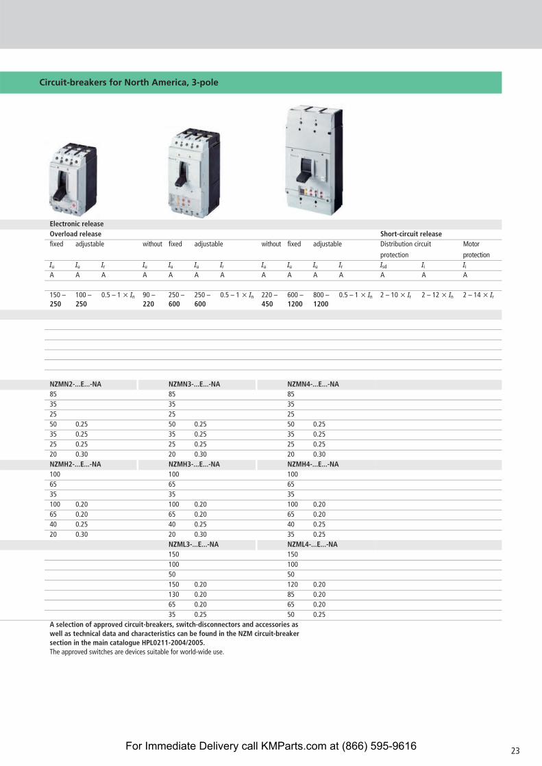
Circuit-breakers for North America, 3-pole
Electronic releaseOverload release Short-circuit releasefixed adjustable without fixed adjustable without fixed adjustable Distribution circuit
protection
Motor
protectionIu Iu Ir Iu Iu Iu Ir Iu Iu Iu Ir Isd Ii Ii
A A A A A A A A A A A A A A
150 – 250
100 – 250
0.5 – 1 x In 90 – 220
250 – 600
250 – 600
0.5 – 1 x In 220 – 450
600 – 1200
800 – 1200
0.5 – 1 x In 2 – 10 x Ir 2 – 12 x In 2 – 14 x Ir
NZMN2-...E...-NA NZMN3-...E...-NA NZMN4-...E...-NA85 85 8535 35 3525 25 2550 0.25 50 0.25 50 0.2535 0.25 35 0.25 35 0.2525 0.25 25 0.25 25 0.2520 0.30 20 0.30 20 0.30NZMH2-...E...-NA NZMH3-...E...-NA NZMH4-...E...-NA100 100 10065 65 6535 35 35100 0.20 100 0.20 100 0.2065 0.20 65 0.20 65 0.2040 0.25 40 0.25 40 0.2520 0.30 20 0.30 35 0.25
NZML3-...E...-NA NZML4-...E...-NA150 150100 10050 50150 0.20 120 0.20130 0.20 85 0.2065 0.20 65 0.2035 0.25 50 0.25
A selection of approved circuit-breakers, switch-disconnectors and accessories as well as technical data and characteristics can be found in the NZM circuit-breaker section in the main catalogue HPL0211-2004/2005. The approved switches are devices suitable for world-wide use.
23For Immediate Delivery call KMParts.com at (866) 595-9616
Think future. Switch to green.
A
http://nzm.moeller.net
Xtra Combinations
Xtra Combinations from Moeller offers a range ofproducts and services, enabling the best possiblecombination options for switching, protection andcontrol in power distribution and automation.
Using Xtra Combinations enables you to findmore efficient solutions for your tasks whileoptimising the economic viability of your machinesand systems.
It provides:� flexibility and simplicity� great system availability� the highest level of safety
All the products can be easily combined with one another mechanically, electrically and digi-tally, enabling you to arrive at flexible and stylishsolutions tailored to your application – quickly,efficiently and cost-effectively. The products areproven and of such excellent quality that theyensure a high level of operational continuity,allowing you to achieve optimum safety for yourpersonnel, machinery, installations and buildings.
Thanks to our state-of-the-art logistics operation,our comprehensive dealer network and our highlymotivated service personnel in 80 countries aroundthe world, you can count on Moeller and ourproducts every time. Challenge us! We are lookingforward to it!
E-Mail: [email protected]: www.moeller.net
© 2004 by Moeller GmbHSubject to changeW1230-7558 GB K.P / DM 04 / 04Printed in the Federal Republic of Germany (04 /04)Article No.: 284720
For Immediate Delivery call KMParts.com at (866) 595-9616