Embed Size (px)
Citation preview

Abstract—This paper overviews various switched flux permanent magnet machines and their design and performance features, with particular emphasis on machine topologies with reduced magnet usage or without using magnet, as well as with variable flux capability. In addition, this paper also describes their relationships with doubly-salient permanent magnet machines and flux reversal permanent magnet machines.
Index Terms—Flux switching, magnetless machine, permanent magnet, switched flux, variable flux.
I. INTRODUCTION Switched flux (SF), or flux switching, machines were
initially developed as one of high frequency inductor generators [1]. Switched flux permanent magnet (SFPM) machines were developed in 1950s [1][2]. In [2], a SFPM machine, i.e. PM single-phase limited angle actuator or more well-known as Laws relay, having 4 stator poles and 4 rotor poles, was developed, while in [1] it was extended to a single phase generator having 4 stator poles and 4 or 6 rotor poles. In order to reduce the cost, the permanent magnet can be replaced by DC coil excitations [3][4], thus, a higher peak torque obtained, albeit with reduced efficiency and torque density. Later, this lead to the pioneering work by Prof. Pollock on both single-phase SF motors and drives for many low cost applications [5]-[14]. Consequently, switched flux machines received world-wide awareness. In parallel, French researchers carried out extensive research activities on 3-phase SFPM machines [15]-[23] in terms of torque/power capability and efficiency, as well as hybrid excitations. At the University of Sheffield, we have been systematically developing single-phase, three-phase, and multi-phase rotary and linear SFPM machines having all stator poles wound and alternate stator poles wound, with multi-teeth, hybrid excited, and magnetless (less magnet or no magnet) for various applications, ranging from automotive to aerospace, and have been investigating their electromagnetic and control performance [24]-[77]. Currently, SFPM machines are under intensive research all over the world, including UK [5][14], [24]-[85], France [15]-[23], China [86-131], Norway [132]-[134], Netherlands [135]-[139], Japan [140][141], Denmark [142], USA [143], South Korea [144][145] and Australia [146], etc.
In this paper, various SFPM machine topologies and their design and performance features will be overviewed, with particular emphasis on SF machines with reduced magnet usage or without magnet, as well as with variable flux
capability. In addition, their relationships with doubly-salient PM (DSPM) machines and flux reversal PM (FRPM) machines will be described.
II. FEATURES OF SFPM MACHINES As shown in Fig.1, the main flux linked with coils is
reversed or switched when the rotor rotates one stator pole pitch, i.e. from Fig.1(a) to Fig.1(b) [1][2].
(a) (b)
Fig.1 Single-phase SFPM machine or Laws relay. Alternative winding dispositions [29] are possible, viz.
short-pitched, full-pitched, and toroidal, as illustrated in Fig. 2 for a single-phase SFPM machine (also possible for a 3-phase SFPM machine). Fig. 2(a) shows the layout of short-pitched concentrated winding wound on each stator pole. From Fig. 2(a), it can be seen that in the slots adjacent to permanent magnets, the two adjacent coil sides carry current of opposite polarity. Hence, it is possible to replace two short-pitched coils by one full-pitched coil, as shown in Fig. 2(b). Alternatively, toroidally wound coils may be employed, Fig. 2(c), which may be beneficial when the machine axial length is very short.
As mentioned in the introduction SF machines usually have PM excitation, as shown in Figs.1 and 2, as well as DC coil excitation [5]-[13], [68], [78]-[81] in order to reduce the cost, Fig.3. It is also possible to have any phase number, as illustrated in Fig.4.
(a) Short-pitched (b) Full-pitched (c) Toroidal
Fig. 2 1-phase SFPM machines having different winding dispositions.
Fig.3 1-phase DC coil excited SF machines.
Switched Flux Permanent Magnet Machines - Innovation Continues
Z.Q. Zhu Department of Electronic and Electrical Engineering, University of Sheffield, Sheffield S1 3JD, U.K.

(a) 1-phase (b) 3-phase Fig. 4 1- and 3-phase SFPM machines.
As shown in Fig.4, for typical SFPM machines, the salient pole rotor is identical to that of a switched reluctance machine, which is simple and robust, without any magnet or coil. Both magnets (or DC excitation coils) and armature coils are housed on stator. The salient pole stator core consists of modular “U”-shaped laminated segments between which are placed circumferentially magnetized PM alternatively with opposite polarity. The stator winding is comprised of concentrated coils, each coil being wound on a pole formed by two adjacent laminated segments and a magnet. Flux focusing may be utilised and low-cost ferrite magnets employed. Since the windings and the magnets are effectively magnetically in parallel, rather than in series as in conventional PM machines, the electric loading and specific torque capability of a SFPM machine can be very high, at least comparable to those of surface-mounted and interior magnet machines. In addition, a high per-unit winding inductance can be readily achieved. Thus, such machines are eminently suitable for constant power operation over a wide speed range, i.e. they can have a high flux-weakening capability.
-6
-3
0
3
6
0 60 120 180 240 300 360
Rotor position (electrical degree)
Flux
-link
age
(mW
b) D-axisQ-axis
Fig. 5 Open-circuit field distributions and typical flux-linkage waveform of single coil in 12/10 stator/rotor pole SFPM machine.
The phase flux-linkage waveform of a SFPM machine is bipolar and the back-emf waveform can be designed to be essentially sinusoidal although concentrated stator windings are employed, Fig. 5. When the rotor pole aligns with one side stator tooth, flux linkage reaches negative peak, whilst when it aligns with another side stator tooth, flux linkage becomes positive peak. When either the rotor pole or the rotor slot aligns with the stator magnet, the flux linkage is zero. The torque production relies on the double saliency of both stator and rotor. However, the torque results predominantly from the PM excitation torque and the reluctance torque is usually negligible. The advantages and disadvantages of SFPM
machines are summarized in Table I. The specific design issues, such as stator and rotor pole number combinations, winding configurations, optimal split ratio, optimal rotor pole width, optimal stator pole width and magnet thickness, stator back-iron thickness etc, are summarized in [27]. By way of example, the optimal rotor pole number is either close to the stator pole number or a multiple thereof, Fig.6, while the optimal ratio of rotor pole width to rotor pole-pitch is approximately 1/3, Fig.7.
TABLE I
ADVANTAGES AND DISADVANTAGES OF CONVENTIONAL SFPM MACHINES Advantages Disadvantages
• Simple and robust rotor • Easier to manage magnet
temperature rise • Flux focusing / low cost ferrite
magnets may be used • Sinusoidal back-emf
waveform – suitable for brushless AC operation
• Reduced copper area • Low over-load capability due
to heavy saturation • Complicated stator • Leakage outside stator • High magnet volume
-1
-0.5
0
0.5
1
1.5
0 4 8 12 16 20 24
Rotor pole number
Nor
mal
ized
mag
netu
de o
f bac
k-em
fAnalytical methodFE method
Fig. 6. Variation of peak emf in one coil with number of rotor teeth in 12-stator pole SFPM machine.
0
0.5
1
1.5
2
2.5
3
0.15 0.2 0.25 0.3 0.35 0.4 0.45
Rotor pole width / rotor pole-pitch
Ave
rage
ele
ctro
mag
netic
torq
ue (N
m)
10-rotor poles11-rotor poles12-rotor poles13-rotor poles14-rotor poles
1/3
Fig. 7. Variation of torque with ratio of rotor pole width to rotor pole-pitch in 12-stator pole SFPM machine.
III. MACHINES HAVING PERMANENT MAGNETS ON STATOR
A. Machines having PMs on Stator When the PMs are located on the stator, the PMs can be
mounted in the stator back-iron (DSPM machines [147][148]), placed on the inner surface of the stator teeth (FRPM machines [149][150]), or sandwiched in the stator teeth (SFPM machines). As pointed out in [26][27], they have same operating principle – switched flux, identical rotor structure – salient pole rotor without magnet or coil, similar stator topology - all having PMs on the salient pole stator which also carries non-overlapping windings. Irrespective of their location, however, the torque results predominantly from the PM excitation torque, i.e. the reluctance torque is negligible, although the torque production mechanism relies on the rotor

saliency. Therefore, their common features may be summarized as follows: • PM on stator; • Salient pole stator with non-overlapping, concentrated
stator winding; • Salient pole rotor without winding and magnet; • Reluctance action; • Negligible reluctance torque.
B. DSPM Machines A major disadvantage of DSPM machines is that due to
unipolar flux-linkage, the torque density is relatively low. This is significantly improved in SFPM machines in which flux-focusing may be readily incorporated and the phase flux-linkage waveform is bipolar, the torque capability is significantly higher than that of a DSPM machines [54]. Meanwhile, the back-emf waveform of a SFPM machine is essentially sinusoidal, while that of a DSPM machine is essentially trapezoidal. Thus, SFPM machine is more appropriate for brushless AC operation, while DSPM machine more suitable for brushless DC operation.
TABLE II
COMPARISON OF ALTERNATIVE PM MACHINES HAVING MAGNETS ON STATOR Doubly-salient Flux-reversal Switched-flux
Machine topologies
Torque production
PM excitation torque (emf), rely on structural saliency and reluctance action, but negligible reluctance torque
Phase number Any phase number, including 1-phase and 3-phase
Stator Salient poles with both PM and armature windings Rotor Salient poles without magnets or coils Winding Non-overlapping concentrated windings Magnet location
Magnets in stator back-iron
Magnets on surface of stator teeth
Magnets in stator teeth
Magnet flux focusing Not in general None Significant
Magnet volume Low Medium High
Flux linkage Unipolar Bipolar Bipolar
Emf
Non-sinusoidal, asymmetric, and
unbalanced 3-phase emfs
Non-sinusoidal symmetrical, and balanced 3-phase
emfs
Sinusoidal, symmetrical, and balanced 3-phase
emfs Appropriate operation mode
Brushless DC Brushless DC Brushless AC
Torque density Low Low High
C. FRPM and SFPM Machines In both SFPM and FRPM machines each coil spans a pair of
alternate magnetic poles. Therefore, the PM flux linkage is bipolar. However, in SFPM machines each coil encircles two laminated modules and a single magnet, and the fluxes produced by the magnet and the coil are in parallel. In contrast, in FRPM machines a pair of magnets is mounted on the surface of each stator tooth and the fluxes produced by the magnet and
the coil are in series. Consequently, the FRPM machines exhibit lower winding inductances and the magnets are more vulnerable to potential irreversible demagnetisation, may have a higher induced eddy current loss, and may experience a significant radial magnetic force, as they are directly exposed to the reluctance variation of the salient rotor poles. Due to flux focusing effect, SFPM machines also exhibit significantly higher torque density than FRPM machines.
Since both the magnets and armature coils are housed in the stator in PM machines having PMs in the stator, the stator copper area is significantly reduced, particularly in SFPM machine in which high magnet number and volume are employed. But as will be described in next section, new topologies are being developed and it is possible to reduce the number and volume of PMs, while maintaining its torque capability.
IV. REDUCTION OF MAGNET USAGE ON SFPM MACHINES In the conventional SFPM machines, the slot area in stator is
significantly reduced due to both PMs and armature coils being on the stator, while the number of magnet segments is high and the amount of magnets used is usually increased, which increases the cost since the rare earth magnet is expensive and normally >50% of total material cost. The large volume of magnets may also increase the eddy current loss in the magnets. Hence, for the SFPM machines, one of the key issues is to reduce the magnet usage. Although the magnet usage in the conventional SFPM machines can be directly reduced, e.g. by reducing the magnet thickness, the torque density is usually reduced as well. As will be shown in this section, the magnet usage in SFPM machines may be reduced by employing multi-tooth, E-core or C-core stators, respectively, Fig.8.
A. Multi-tooth SFPM Machines A multi-tooth SFPM machine [34] produces higher torque
when the electric loading is low, Fig.9, it requires less magnets, coils and laminated modules, thus the material and manufacturing costs can be significantly reduced. However, it effectively results in more stator teeth and, hence requires more rotor teeth. In [35], it is shown that the multi-tooth SFPM machine reduces the magnet usage by a half relative to the conventional SFPM machines. However, it maintains almost the same slot area as that of the conventional machines due to the multi-tooth structure which limits the slot area when the split ratio is fixed.
(a) Conventional (b) Multi-tooth (c) E-core (d) C-core
Fig.8 Alternative SFPM machine topologies employing much less magnets.
B. E-core and C-cored SFPM Machines In order to reduce the magnet usage and cost, and increase
the slot area, the concept of E-core SFPM machines was proposed and systematically investigated in [45]. It employs only a half volume of magnets and exhibits larger torque density relative to the conventional SFPM machines, Fig.9. In
[47], it is shown that the middle tooth in the E-core stator may be removed without sacrificing the torque density, Fig.9, although the power factor is found to be reduced.
It is worth noting that in all of these SFPM machines having multi-tooth, E-core and C-core stators, the magnet usage is significantly reduced (halved in above mentioned examples), while the torque density is also increased. As shown in Fig. 9, only when the electric loading (current) is very high, their torque will be less than that in the conventional SFPM machine due to higher armature reaction and magnetic saturation.
0
1
2
3
4
5
6
7
8
0 10 20 30 40 50 60
Q-axis current (A)
Torq
ue (N
m)
Conventional, 12/10
E-core, 6/11
C-core, 6/13Multi-tooth, 6/19
Rated current
Fig.9 Comparison of torque against current characteristics in alternative SFPM machines employing much less magnets.
V. MAGNETLESS SWITCHED FLUX MACHINES Although PM machines exhibit high torque density and high
efficiency, the rare earth magnets, e.g. NdFeB, are expensive and have limited resources. Further, the working environmental temperature may also limit their application due to potential irreversible demagnetisation. One of the possible solutions is to replace the magnet excitation by DC coil excitation.
In the conventional DC coil excited synchronous machine the field winding is on the rotor, and, consequently, slip-rings are required to supply the field current. In PM machines having magnets on the stator, e.g. DSPM and SFPM machines, Section III, the excitation of magnetic field may be realized by a DC coil on the stator, as previous done in Laws relay [3][4] and single-phase SF machines [5]-[13], in which the 1-phase DC coil excited SF machine and its controller were proposed and extensively analyzed for automotive and power tool applications due to the extremely low cost of the machine and drive system. Since the field winding is excited by unipolar current, it can be directly connected in parallel or in series with the power converter which feeds the bipolar current into the armature winding. The 1-phase FS machine was shown to exhibit a higher output power density than the equivalent universal and induction machines, and comparable efficiency to that of the induction machine. Of course, as in any type of 1-phase machines, the 1-phase FS machine also has problems of low starting torque, large torque ripple, and fixed rotating direction.
In [152][154], a DC coil excited DS machine was proposed. But their torque capability is limited due to the inherent relatively low torque capability of DS machines, as mentioned earlier.
It is well-known that the magnetic potential source of permanent magnets can be physically modelled by surface currents. However, surface current sheets are not possible to
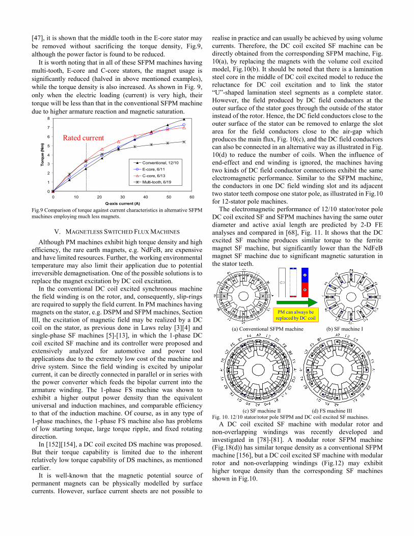
realise in practice and can usually be achieved by using volume currents. Therefore, the DC coil excited SF machine can be directly obtained from the corresponding SFPM machine, Fig. 10(a), by replacing the magnets with the volume coil excited model, Fig.10(b). It should be noted that there is a lamination steel core in the middle of DC coil excited model to reduce the reluctance for DC coil excitation and to link the stator “U”-shaped lamination steel segments as a complete stator. However, the field produced by DC field conductors at the outer surface of the stator goes through the outside of the stator instead of the rotor. Hence, the DC field conductors close to the outer surface of the stator can be removed to enlarge the slot area for the field conductors close to the air-gap which produces the main flux, Fig. 10(c), and the DC field conductors can also be connected in an alternative way as illustrated in Fig. 10(d) to reduce the number of coils. When the influence of end-effect and end winding is ignored, the machines having two kinds of DC field conductor connections exhibit the same electromagnetic performance. Similar to the SFPM machine, the conductors in one DC field winding slot and its adjacent two stator teeth compose one stator pole, as illustrated in Fig.10 for 12-stator pole machines.
The electromagnetic performance of 12/10 stator/rotor pole DC coil excited SF and SFPM machines having the same outer diameter and active axial length are predicted by 2-D FE analyses and compared in [68], Fig. 11. It shows that the DC excited SF machine produces similar torque to the ferrite magnet SF machine, but significantly lower than the NdFeB magnet SF machine due to significant magnetic saturation in the stator teeth.
PM can always be replaced by DC coil
(a) Conventional SFPM machine (b) SF machine I
(c) SF machine II (d) FS machine III
Fig. 10. 12/10 stator/rotor pole SFPM and DC coil excited SF machines. A DC coil excited SF machine with modular rotor and
non-overlapping windings was recently developed and investigated in [78]-[81]. A modular rotor SFPM machine (Fig.18(d)) has similar torque density as a conventional SFPM machine [156], but a DC coil excited SF machine with modular rotor and non-overlapping windings (Fig.12) may exhibit higher torque density than the corresponding SF machines shown in Fig.10.

0
2
4
6
8
10
0 4 8 12 16 20 24 28
Q-axis current density (A/mm2)
Elec
trom
agne
tic to
rque
(Nm
)FS, Jf = 10A/mm^2FS, Jf = 20A/mm^2FS, Jf = 30A/mm^2FS, Jf = 60A/mm^2FS, Jf = 80A/mm^2FSPM, Br = 0.4TFSPM, Br = 1.2T
Fig.11 Comparison of torque-current characteristics of 12/10 stator/rotor pole SFPM and DC coil excited SF machines.
Fig.12 DC coil excited SF machines having modular rotor.
VI. VARIABLE FLUX SFPM MACHINES The PM flux is not adjustable, which may limit the low speed
over load capability and high speed operation, and reduce overall efficiency. Hence, there is a need to adjust the PM flux. This is usually achieved in vector control by employing either position or negative d-axis current, however, the q-axis current then needs to be reduced accordingly.
A. Variable-flux PM Machines Variable-flux PM (VFPM) machines include some means of
adjusting the level of PM flux and are of interest today as they allow flexibility in terms of optimizing efficiency across a machine operation cycle. Many examples of VFPM machines have been studied and documented [156]-[158] including hybrid-excited machines with field coils and machines with mechanical adjustment. Some features of variable flux PM machines are summarized in Table III.
TABLE III
VARIABLE FLUX PM MACHINES Advantages Disadvantages
• Easy to achieve constant power operation (flux weakening)
• Potentially enhanced low speed torque
• Reduced risk of high open-circuit back-emf at high speed during flux weakening
• Possible high efficiency operation over whole torque and speed region
•Complicated structure •Torque density likely reduced •Limited flux enhancing capability
due to magnetic saturation •Extra DC source required, or •Extra mechanical means required
for mechanically adjusted flux
B. Mechanically Adjusted Variable Flux PM Machines Fig.13 shows the mechanical mechanism utilized for
providing flux adjustment in SFPM machines. A short circuit
bar is located behind the stator back-iron which can be moved to provide a short circuit path for the magnet flux. In the normal position, Fig.13 (a), the magnet flux links the rotor as in the conventional SFPM machine, Figs.14 (a) and (b), but when the bar is moved to the closed weakening position, Fig.13(b) and Fig.14(c), much of the magnet flux is short circuited. Thus, the magnet flux linkage and the back-emf can be reduced, as shown in Fig.15. However, as a passive means for adjusting the magnet flux, it has disadvantages in that it is impossible to enhance the flux and it requires an extra mechanical mechanism.
(a) Normal position (b) Closed position
Fig.13.Mechanically adjusted SFPM machine concept.
(a) Flux distribution in conventional SFPM machine
(b) Normal position (c) Closed flux weakening position
Fig.14 Mechanically adjusted variable flux SFPM machines.
Fig.15 Performance of mechanically adjusted variable flux SFPM machines.
C. Hybrid PM and DC Coil Excited PM Machines Hybrid excited PM machines [156]-[158] can be further
grouped based on the location of coil excitation sources on the stator or rotor, and the magnetic circuit configuration of the permanent-magnet and field-coil flux paths, series or parallel.
Hybrid excited DSPM machines, Fig.16(a), were investigated in [151]-[154]. In addition to the inherent relatively low torque density as mentioned earlier, they have long end windings for the field windings which over-lap with the armature windings.
A novel hybrid excited SFPM machine employing non-overlapping field and armature windings was proposed in [19], Fig. 16(c). However, the machine outer diameter is significantly enlarged in order to accommodate the DC field winding, which significantly reduces the torque density. The magnets in the SFPM machine may be partially replaced by the

DC excitation windings and consequently several hybrid excited topologies were developed [41][66][86] Fig. 16(b), but they have overlapping armature and field windings, albeit with significantly reduced torque capability.
A new hybrid excited SFPM machine was developed in [46] to eliminate the foregoing disadvantages. It employs non-overlapping field and armature windings and also exhibits a simple structure. Compared with the conventional SFPM machine, the magnet material in the proposed hybrid excited SFPM machine is also halved while the torque density is improved since it is based on the developed E-core SFPM machine [45]. Fig. 17 compares predicted and measured torque-DC excitation current characteristics.
(a) Hybrid DSPM machine (b) Hybrid excited SFPM machine I
(c) Hybrid excited SFPM machine II (d) Hybrid excited SFPM machine III
-E-core Fig.16 Hybrid SFPM machines.
0
0.2
0.4
0.6
0.8
1
1.2
-20 -15 -10 -5 0 5 10 15 20
DC excitation current (A)
Torq
ue (N
m)
11-rotor poles, 2D FE
13-rotor poles, 2D FE
11-rotor poles, measured
13-rotor poles, measured
Fig.17 Torque-DC excitation current characteristics of E-core hybrid excited SFPM machine.
VII. OTHER SFPM MACHINE TOPOLOGIES In addition to the forgoing mentioned SFPM machines
topologies, numerous other machine topologies have been developed recently, to name a few:
• Linear and tubular SFPM machines [48][65][69][76][77][89][90][118][120][122][135][136];
• Fault-tolerant SFPM machines [40][45][82-85][93][127], Fig. 8(c) and Fig. 18(b);
• Axial-field SFPM machines, [71]; • Transverse-flux SFPM machines, [67], Fig.18(e); • Modular rotor SFPM machines, [155], Figs. 18(d); • Multi-PM sandwiched SFPM machines, Fig.18(c)
[126][142]; • Multi-3-phase inverters fed SFPM machines [88].
(a) Conventional SFPM machines having all poles wound
(b) SFPM machines having alternate poles wound
(c) Multi-PM sandwiched SFPM (d) Modular rotor SFPM PM
Stator Core
Rotor Core
Support
Winding
(e) Transverse-flux SFPM Fig. 18. Other SFPM machines.
VIII. CONCLUSIONS Numerous novel and new SFPM machine topologies have
been developed over the last decade. They are briefly reviewed in this paper with particular emphasis on SF machines with reduced magnet usage or without using magnet, as well as with variable flux capability.
Since the torque results predominantly from the PM excitation torque and the reluctance torque is usually negligible, control of a SFPM machine is similar to that surface-mounted PM machines, but with large winding inductance [72][75].
Due to their novel features, e.g. PM on the stator, simple and robust rotor, flux focusing, and higher torque density compared with conventional doubly-salient and flux-reversal PM machines, as well as at least similar torque/power density compared with conventional surface-mounted and interior PM machines, SFPM machines have significant potential.
ACKNOWLEDGEMENTS
This work is partially supported by the Engineering and Physics Science Research Council, UK, Ref. EP/F016506/1, and IMRA UK Research Centre. The contributions made by the

PhD and ex-PhD students at the University of Sheffield, Dr Y. Pang, Dr J.T. Chen, Dr A.S. Thomas, Dr Y. Chen, Dr R.L. Owen, Dr X. Liu, Mr M. Al-ani, Mr Z. Azar, Dr W. Hua, Mr W. Min, and Dr H.S. Liu, are greatly appreciated.
REFERENCES [1] S. E. Rauch and L. J. Johnson, “Design principles of flux-switching
alternators,” AIEE Trans. 74III, pp.1261-1268, 1955. [2] A.E. Laws, “An electromechanical transducer with permanent magnet
polarization,” Technical Note No.G.W.202, Royal Aircraft Establishment, Farnborough, UK, 1952.
[3] C. Dawson, and H.R. Bolton, “Design of a class of wide-angle limited-rotation rotary actuators,” IEE Proc., vol.126, no.4, pp.345-350, 1979.
[4] H. R. Bolton and Y. Shakweh, “Performance prediction of Laws’s relay actuator,” IEE Proc., vol.137, pt.B, no.1, pp.1-13, 1990.
[5] C. Pollock, and M. Wallace, “The flux-switching motor, a DC motor without magnets or brushes,” IEEE Industry Applications Society Annual Meeting, 1999, pp.1980-1987.
[6] C. Pollock, and M. Brackley, “Comparison of the acoustic noise of flux-switching and a switched reluctance drives,” IEEE Trans. Industry Applications, Vol. 39, No. 3, pp.826-834, 2003.
[7] K. S. Chai and C. Pollock, “Using genetic algorithms in design optimization of the flux switching motor,” Int. Conf. on Power Electronics, Machines and Drives, 2002, pp. 540-545.
[8] C. Pollock, H. Pollock, R. Barron, R. Sutton, J. Coles, D. Moule, and A. Court, “Flux switching motors for automotive applications,” IEEE Trans. on Industry Applications, vol. 42, pp. 1177-1184, 2006.
[9] H. Pollock, C. Pollock, R. T. Walter, and B.V. Gorti, “Low cost, high power density, flux-switching machines and drives for power tools,” IEEE Industry Applications Society Annual Meeting, 2003, pp.1451-1457.
[10] C. Pollock, H. Pollock, and M. Brackley, “Electronically controlled flux switching motors: a comparison with an induction motor driving an axial fan,” The 29th Annual Conference of the IEEE Industrial Electronics Society, IECON '03, 2003, pp. 2465-2470.
[11] K. N. Ochije and C. Pollock, “Simulink model of controlled power factor flux switching generator system for embedded power generation,” IEEE Industry Applications Society Annual Meeting, 2005, pp. 2657-2664.
[12] K. N. Ochjie and C. Pollock, “Design/performance of a flux switching generator system for variable speed applications,” IEEE Industry Applications Society Annual Meeting, 2005, pp. 1567-1574.
[13] K. N. Ochije and C. Pollock, “Controlled series compensation of high speed brushless flux switching generators for direct drive variable speed application,” IEEE Electric Ship Technologies Symposium, 2007, pp. 408-413.
[14] C. Yi, C. Pollock, and H. Pollock, “A permanent magnet flux switching motor for low energy axial fans,” IEEE Industry Applications Society Annual Meeting, 2005, pp. 2168-2175.
[15] A. Mailfert, H. Kubler, and J. Zhou, “Hybrid stepping motors comparative experimental results,” Int. Conf. on Electrical Machines, pp. 781-783, 1987.
[16] E. Hoang, A. H. Ben-Ahmed and J. Lucidarme, “Switching flux permanent magnet polyphased synchronous machines,” 7th European Conf. on Power Electronics and Applications, pp.903-908, 1997.
[17] E. Hoang, M. Gabsi, M. Lecrivain and B. Multon, “Influence of magnetic losses on maximum power limits of synchronous permanent magnet drives in flux-weakening mode,” IEEE Industry Applications Society Annual Conference, pp.299-303, 2000.
[18] Y. Amara, E. Hoang, M. Gabsi, M. Lecrivain, and S. Allano, “Design and comparison of different flux-switch synchronous machines for an aircraft oil breather application”, The 2nd IEEE Int. Conf. on Signals, Systems, Decision and Information Technology, March 26-29, 2003.
[19] E. Hoang, M. Lecrivain, and M. Gabsi, “A new structure of a switching flux synchronous polyphased machine with hybrid excitation,” European Conf.Power Electronics and Applications, 2007, pp. 1–8.
[20] E. Hoang, M. Lecrivain, S. Hlioui, and M. Gabsi, “Hybrid excitation permanent magnet synchronous machines optimally designed for hybrid and full electric vehicles,” Int Conf on Power Electronics (ICPE2011) – ECCE-Asia, 2011, Paper TuD1-2.
[21] E. Hoang, M. Lecrivain, and M. Gabsi, “3-D thermal model of an hybrid excitation flux switching synchronous machine using a 2-D FE method
software,” Int. Symposium Power Electronics Electrical Drives Automation and Motion (SPEEDAM), 2010, pp. 101-104.
[22] E. Hoang, S. Hlioui, M. Lecrivain, and M. Gabsi, “Experimental comparison of lamination material case of switching flux synchronous machine with hybrid excitation,” European Conf. Power Electronics and Applications, 2009, pp. 1-7.
[23] X. Ojeda, G. J. Li, and M. Gabsi, “Fault diagnosis using vibration measurements of a flux-switching permanent magnet motor,” IEEE Int. Symp. Industrial Electronics, 2010, pp. 2091-2096.
[24] Z.Q. Zhu, “Study of Laws relay,” Industrial Technical Report, University of Sheffield, UK, 1988.
[25] Z.Q. Zhu, Y. Pang, D. Howe, S. Iwasaki, R. Deodhar, and A. Pride, “Analysis of electromagnetic performance of flux-switching PM machines by nonlinear adaptive lumped parameter magnetic circuit model,” IEEE Trans. Magnetics, vol.41, no.11, pp.4277-4287, 2005.
[26] Z.Q. Zhu, and D. Howe, “Electrical machines and drives for electric, hybrid, and fuel cell vehicles,” Proc. IEEE, vol.95, no.4, pp.746-765, 2007.
[27] Z.Q. Zhu, and J.T. Chen, “Advanced flux-switching permanent magnet brushless machines,” (invited paper), IEEE Trans. Magnetics, vol.46, no.6, pp.1447-1453, 2010.
[28] Z.Q. Zhu, Y. Pang, W. Hua, M. Cheng, and D. Howe, “Investigation of end-effect in PM brushless machines having magnets in the stator,” J. Applied Physics, vol.99, no.8, 08R319, 1-3, April 2006.
[29] Y. Chen, Y.S. Chen, Z.Q. Zhu, and D. Howe, and Y.Y. Ye, “Starting torque of single-phase flux-switching permanent magnet motors,” IEEE Trans. Magnetics, vol.42, no.10, pp.3416-3418, 2006.
[30] Y. Pang, Z. Q. Zhu, D. Howe, S. Iwasaki, R. Deodhar, and A. Pride, “Eddy current loss in the frame of a flux-switching permanent magnet motor,” IEEE Trans. Magnetics, vol.42, no.10, pp.3413-3415, 2006.
[31] W. Hua, M. Cheng, Z.Q. Zhu, and W.X. Zhao, “Comparison of electromagnetic performance of brushless machines having magnets in stator and rotor,” J. Applied Physics, vol.103, 07F124-1, 3 pages, 2008.
[32] W. Hua, M. Cheng, Z.Q. Zhu, and D. Howe, “Analysis and optimization of back-EMF waveform of a novel flux-switching PM motor,” IEEE Trans. Energy Conversions, vol.23, no.3, pp.727-733, 2008.
[33] Y. Chen, Z.Q. Zhu, and D. Howe, “Three-dimensional lumped parameter magnetic circuit model for analyzing single-phase flux-switching permanent magnet motor,” IEEE Trans. Industry Applications, vol.44, no.6, pp.1701-1710, Nov./Dec. 2008.
[34] Z. Q. Zhu, J. T. Chen, D. Howe, S. Iwasaki, and R. Deodhar, “Analysis of a novel multi-tooth flux-switching permanent magnet brushless ac machines for high torque direct drives,” IEEE Trans. Magnetics, vol.44, no.11, pp.4313-4316, 2008.
[35] J. T. Chen, Z.Q. Zhu, and D. Howe, “Stator and rotor pole combination and optimal design of multi-tooth flux-switching PM brushless AC machines,” IEEE Trans. Magnetics, vol.44, no.12, pp.4659-4667, 2008.
[36] S. Iwasaki, R. Deodhar, Y. Liu, A. Pride, Z.Q. Zhu, and J. Bremner, “Influence of PWM on the proximity loss in permanent magnet brushless AC machines,” IEEE Trans. Industry Applications, vol.45, no.4, pp.1359-1367, 2009.
[37] A.S. Thomas, Z.Q. Zhu, G.W. Jewell, “Proximity losses study in a high speed flux switching permanent magnet machine,” IEEE Trans. on Magnetics, vol.45, no.10, pp.4748-4751, 2009.
[38] Z. Q. Zhu, A.S. Thomas, J.T. Chen, and G.W. Jewell, “Cogging torque in flux-switching permanent magnet machines,” IEEE Trans. Magnetics, vol.45, no.10, pp.4708-4711, 2009.
[39] A. S. Thomas, Z.Q. Zhu, R. Owen, G. W. Jewell, and D. Howe, “Multi-phase flux-switching permanent magnet brushless machine for aerospace applications,” IEEE Trans. Industry Applications, vol.45, no.6, pp.1971-1981, 2009.
[40] R. Owen, Z. Q. Zhu, A. Thomas, G. W. Jewell, and D. Howe, “Alternate pole wound flux switching permanent magnet brushless AC machines,” IEEE Trans. Industry Applications, vol.46, no.2, pp.790-797, 2010.
[41] R L. Owen, Z.Q. Zhu, and G. W. Jewell, “Novel hybrid-excited flux-switching permanent-magnet machines with iron bridges,” IEEE Trans. Magnetics, vol.46, no.6, pp.1726-1729, 2010.
[42] J.T. Chen, and Z.Q. Zhu, “Winding configurations and optimal stator and rotor pole combination of flux-switching PM brushless AC machines,” IEEE Trans. Energy Conversion, vol.25, no.2, pp.293-302, 2010.
[43] J.T. Chen, and Z.Q. Zhu, “Influence of rotor pole number on optimal parameters in flux-switching PM brushless AC machines by lumped parameter magnetic circuit model,” IEEE Trans. Industry Applications, vol.46, no.4, pp.1381-1388, 2010.

[44] J.T. Chen and Z.Q. Zhu, “Comparison of all and alternate poles wound flux-switching PM machines having different stator and rotor pole numbers,” IEEE Trans. Industry Applications, vol.46, no.4, pp.1406-1415, 2010.
[45] J. T. Chen, Z. Q. Zhu, S. Iwasaki, R. Deodhar, “A novel E-core flux-switching PM brushless AC machine for direct-drive applications,” IEEE Trans. Industry Applications, vol.47, no.3, pp.1273-1282, 2011.
[46] J. T. Chen, Z. Q. Zhu, S. Iwasaki, R. Deodhar, “A novel hybrid excited switched-flux brushless AC machine for EV/HEV applications,” IEEE Trans. Vehicular Technology, vol.60, no.4, pp.1365-1373, 2011.
[47] J. T. Chen, Z. Q. Zhu, S. Iwasaki, R. Deodhar, “Influence of slot opening on optimal stator and rotor pole combination and electromagnetic performance of flux-switching PM brushless AC machines,” IEEE Trans. Industry Applications, in Press.
[48] W. Min, J. T. Chen, Z. Q. Zhu, Y. Zhu, M. Zhang, G. H. Duan, ”Optimization and comparison of novel E-core and C-core linear switched flux PM machines,” IEEE Trans. Magnetics, in Press.
[49] A.S. Thomas, Z.Q. Zhu, G.W. Jewell, “Comparison of switched flux and surface mounted permanent magnet generators for high speed applications,” Proc. IET, Electrical Systems in Transportation, in Press.
[50] W. Hua, M. Cheng, Z.Q. Zhu, and D. Howe, “Study on static characteristics of novel flux-switching doubly-salient PM machine,” Proc. Chinese Society of Electrical Engineering, vol.26, no.13, pp.129-134, 2006.
[51] W. Hua, M. Cheng, Z.Q. Zhu, and D. Howe, “Study on static characteristics of 2-phase flux-switching doubly-salient PM machine,” Trans. China Electrotechnical Society, vol.21, no.6, pp.70-77, 2006.
[52] A.S. Thomas, Z.Q. Zhu, G.W. Jewell, D. Howe, “Flux-switching PM brushless machines with alternative stator and rotor pole combinations,” J. Asian Electric Vehicles, vol.6, no.1, pp.1103-1110, 2008.
[53] J. T. Chen, Z. Q. Zhu, and Z. P. Xia, “Coil connections and winding factors in flux-switching PM brushless AC machines,” Int. J. for Computation and Mathematics in Electrical and Electronic Engineering (COMPEL), vol.30, no. 1, pp.84-97, 2011.
[54] W. Hua, Z.Q. Zhu, M. Cheng, Y. Pang, and D. Howe, “Comparison of flux-switching and doubly-salient permanent magnet brushless machines,” Proc. 8th Int. Conf. Electrical Machines and Systems, September 27 ~ 29, 2005, Nanjing, China, pp.165-170.
[55] W. Hua, M. Cheng, Z. Q. Zhu, and D. Howe, “Design of flux-switching permanent magnet machine considering the limitation of inverter and flux-weakening capability,” IEEE Industry Applications Society Annual Conf., 2006, paper 60p7, 6 pages.
[56] W. Hua, M. Cheng, Z.Q. Zhu, and D. Howe, “Comparative study of 2-phase flux-switching and doubly-salient permanent magnet brushless machines,” Proc. Int. Conf. Elec. Machines, (ICEM2006), Crete Island, Greece, 2-5 Sept. 2006, paper no: OMM1-1, 6 pages.
[57] Y. Chen, Z.Q. Zhu, and D. Howe, “Rotor eddy current loss in 1-phase high-speed permanent magnet brushless DC motor,” Proc. IEEE Industry Application Society Annual Meeting, 2007, New Orleans, USA, paper IAS15p1.
[58] Y. Pang, Z. Q. Zhu, D. Howe, S. Iwasaki, R. Deodhar, and A. Pride, “Comparative study of flux-switching and interior permanent magnet machines,” Int. Conf. Electrical Machines and Systems (ICEMS2007), 8-11 October, 2007, Seoul, Korea, CDROM, paper PM3-06, pp.757-762
[59] Z. Q. Zhu, J.T. Chen, Y. Pang, D. Howe, S. Iwasaki, and R. Deodhar, “Modelling of end-effect on electromagnetic torque in flux-switching permanent magnet machine,” Int. Conf. Electrical Machines and Systems (ICEMS2007), 8-11 October, 2007, Seoul, Korea, CDROM, paper PMP-36, pp.943-948.
[60] Z. Q. Zhu, Y. Pang, J.T. Chen, R. Owen, D. Howe, S. Iwasaki, R. Deodhar, and A. Pride, “Analysis and reduction of magnet eddy current loss in flux-switching permanent magnet machines,” IET, power Electronics, Machines and Drives, 2-4 April, 2008, York, UK, pp.120-124.
[61] Y. Pang, Z. Q. Zhu, D. Howe, S. Iwasaki, R. Deodhar, and A. Pride, “Investigation of iron loss in flux-switching permanent magnet machines,” IET, Power Electronics, Machines and Drives, 2-4 April, 2008, York, UK, pp.460-464.
[62] J.T. Chen, Z.Q. Zhu, and D. Howe, “A dual-lumped parameter magnetic circuit model accounting for the cross-coupling effect, with particular reference to flux-switching permanent magnet machines,” IET, power Electronics, Machines and Drives, 2-4 April, 2008, York, UK, pp.111-115.
[63] Z.Q. Zhu, Y. Pang, J.T. Chen, Z.P. Xia, and D. Howe, “Influence of design parameters on output torque of flux-switching permanent magnet
machines,” Proc. IEEE Vehicle Power and Propulsion Conference (VPPC), 3-5 September 2008, Harbin, China, pp.1-6, Digest Book, p.83.
[64] A.S. Thomas, Z.Q. Zhu, G.W. Jewell, D. Howe, “New 3-phase flux-switching PM brushless machines with alternative stator and rotor pole combinations,” Proc. Int. Conf. Elec. Machines and Systems (ICEMS), Wuhan, China, 17-20 October, 2008, paper SMO-55.
[65] Z.Q. Zhu, X. Chen, J. T. Chen, D. Howe, and J.S. Dai, “Novel linear fault-tolerant flux-switching permanent-magnet machines,” Proc. Int. Conf. Elec. Machines and Systems (ICEMS), Wuhan, China, 17-20 October, 2008, paper SMO-48.
[66] R. L. Owen, Z.Q. Zhu, and G.W. Jewell, “Hybrid excited flux-switching permanent magnet machines,” 13th European Conf. Power Electronics and Applications, EPE2009, 2009, Barcelona, Spain, pp.1-10.
[67] J. Yan, H. Lin, Y. Huang, H. Liu, and Z.Q. Zhu, “Magnetic field analysis of a novel flux switching transverse flux permanent magnet wind generator with 3-D FEM,” Power Electronics Specialist Conf., November 2-5, 2009, Taipei, Taiwan.
[68] J. T. Chen, Z. Q. Zhu, S. Iwasaki, and R. Deodhar, “Low cost flux-switching brushless AC machines,” IEEE Vehicle Power and Propulsion Conf., 1-3 Sept., 2010, Lille, Fracnce, VPPC 2010, Paper RT6/95-13475.
[69] W. Min, J. T. Chen, Z. Q. Zhu, Y.Zhu, and G. H. Duan, “Optimization of linear flux switching permanent magnet motor,” IEEE Vehicle Power and Propulsion Conf., 1-3 Sept., 2010, Lille, Fracnce, VPPC 2010, Paper RT6/95-93051.
[70] J. T. Chen, Z. Q. Zhu, S. Iwasaki, and R. Deodhar, “Comparison of losses and efficiency in alternate flux-switching permanent magnet machines,” XIX Int. Conf. on Elec. Machines, ICEM2010,6-8 Sept. 2010, Rome, Italy, paper RF-002259-PMM2.
[71] M. Lin, L. Zhang, X. Zhao, X. Li, and Z.Q. Zhu, “Finite element processing methods to peripheral flux leakage in axial field flux-switching PM machines,” Compumag 2011.
[72] Z.Q. Zhu, and Z. Azar, “Influence of cross-coupling and end-effect on torque-speed characteristics of switched flux permanent magnet machines,” IEEE 8th Int. Conf. Power Electronics – ECCE Asia (ICPE2011-ECCE Asia), Jeju, Korea, May 30~ June 3, 2011.
[73] Z.Q. Zhu, and X. Liu, “Individual and global optimization of switched flux permanent magnet motors,” Int. Conf. Electrical Machines and Systems, ICEMS 2011, 20-23 August 2011, Beijing, China.
[74] R. Owen, Z.Q. Zhu, J.B. Wang, D. A. Stone, and I. Urquhart, “Mechanically adjusted variable-flux concept for switched-flux permanent-magnet machines,” Int. Conf. Electrical Machines and Systems, ICEMS 2011, 20-23 August 2011, Beijing, China.
[75] H. Liu, Z.Q. Zhu, E. Mohamed, Y. Fu, and X. Qi, “Flux-weakening control of PMSM having large winding inductance, accounting for resistive voltage drop and inverter nonlinearities,” IEEE Trans. Power Electronics, in press.
[76] J. B. Wang, W. Y. Wang, K. Atallah, and D. Howe, “Design considerations for tubular flux-switching PM machines,” IEEE Trans. Magnetics, vol.44, no.11, pp.4026-4032, 2008.
[77] J. B. Wang, W. Wang, R. Clark, K. Atallah, and D. Howe, “A tubular flux-switching permanent magnet machine,” J. Applied Physics, vol. 103, pp. 07F105-07F105-3, 2008.
[78] S. Iwasaki, and R. Deodhar, “An electrical machine,” UK Patent, GB0904690.1, Mar. 2009.
[79] A. Zulu, B. Mecrow, and A. Armstrong, “A wound-field three-phase flux-switching synchronous motor with all excitation sources on the stator,” IEEE Trans. Industry Applications, vol. 46, pp. 2363-2371, 2010.
[80] A. Zulu, B. C. Mecrow, and M. Armstrong, “Prediction of performance of a wound-field segmented-rotor flux-switching synchronous motor using a dq-equivalent model,” Int. Conf. on Electrical Machines, 2010, pp. 1-6. IEEE Trans. on Industrial Electronics, 2011, in press.
[81] A. Zulu, B. C. Mecrow, and M. Armstrong, “Topologies for wound-field three-phase segmented-rotor flux-switching machines,” IET Int. Conf. Power Electronics, Machines and Drives (PEMD 2010), 2010, pp. 1-6.
[82] T. Raminosoa, C. Gerada, and M. Galea, “Design considerations for a fault-tolerant flux-switching permanent-magnet machine,” IEEE Trans. Industrial Electronics, vol. 58, no.7, pp. 2818-2825, Jul. 2011.
[83] T. Raminosoa and C. Gerada, “A comparative study of permanent magnet - synchronous and permanent magnet - flux switching machines for fault tolerant drive systems,” IEEE Energy Conversion Congress and Exposition, 12-16 Sept. 2010, pp. 2471-2478.

[84] T. Raminosoa and C. Gerada, “Novel fault tolerant design of flux switching machines,” Int. Conf. Power Electronics, Machines and Drives, 5th IET , Apr. 2010, pp. 1-6.
[85] T. Raminosoa and C. Gerada, “Fault tolerant winding technology comparison for flux switching machine,” Int. Conf. Electrical Machines, 6-8 Sept. 2010, pp. 1-6.
[86] W. Hua, M. Cheng, and G. Zhang, “A novel hybrid excitation flux-switching motor for hybrid vehicles,” IEEE Trans. Magnetics, vol.45, no.10, pp. 4728-4731, Dec. 2009.
[87] J. Zhang, M. Cheng, and Z. Chen, “Investigation of a new stator interior PM machine,” Proc. IET Elect. Power Appl., vol.2, no.2, pp.77-87, 2008.
[88] W. Zhao, M. Cheng, W. Hua, H. Jia, and R. Cao, “Back-EMF harmonic analysis and fault-tolerant control of flux-switching permanent-magnet machine with redundancy,” IEEE Trans. Industrial Electronics, vol. 58, no.5, pp. 1926-1935, May 2011.
[89] L. Huang, H. Yu, M. Hu, J. Zhao, and Z. Cheng, “A novel flux-switching permanent-magnet linear generator for wave energy extraction application,” IEEE Trans. Magnetics, vol. 47, pp. 1034-1037, 2011.
[90] L. Huang, H. Yu, J. Zhao, and M. Q. Hu, “A novel flux-switching permanent magnet linear generator for wave energy extraction,” 14th Biennial IEEE Conf. Electromagnetic Field Computation, 9-12 May 2010, pp.1.
[91] W. Zhao, M. Cheng, W. Hua, L. Xu, R. Cao, and Y. Du, “Post-fault operation of redundant flux-switching permanent-magnet motors using harmonic injected current,” Int. Conf. Electrical Machines and Systems, 10-13 Oct. 2010, pp. 868-872.
[92] W. Zhao, M. Cheng, W. Hua, H. Jia, R. Cao, and W. Wang, “Remedial operation of a fault-tolerant flux-switching permanent magnet motor for electric vehicle applications,” IEEE Vehicle Power and Propulsion Conf., 1-3 Sept. 2010, pp. 1-6.
[93] W. Zhao, M. Cheng, K. T. Chau, J. Ji, W. Hua, and R. Cao, “A new modular flux-switching permanent-magnet machine using fault-tolerant teeth,” 14th Biennial IEEE Conf. Electromagnetic Field Computation, 9-12 May 2010, pp.1.
[94] W. Hua, G. Zhang, M. Cheng, and X. Sun, “Comparison of flux-regulation capability of a hybrid-excited flux-switching machine with different magnet materials,” 14th Biennial IEEE Conf. Electromagnetic Field Computation , 9-12 May 2010, pp. 1.
[95] W. Hua, G. Zhang, M. Cheng, and X. K. Sun, “Comparison of flux-regulation capability of a hybrid-excited flux-switching machine with different magnet materials,” 14th Biennial IEEE Conf. Electromagnetic Field Computation, 2010, pp. 1-1.
[96] W. Hua, G. Zhang, and M. Cheng, “Electromagnetic performance analysis of hybrid-excited flux-switching machines for electrical vehicles by an improved magnetic network model,” IEEE Vehicle Power and Propulsion Conf., 2010, pp. 1-5.
[97] H. Jia, M. Cheng, W. Hua, W. Zhao, and W. L. Li, “Torque ripple suppression in flux-switching PM motor by harmonic current injection based on voltage space-vector modulation,” IEEE Trans. Magnetics, vol. 46, pp. 1527-1530, 2010.
[98] G. P. Dong, M. Cheng, and W. Hua, “Modeling of a novel hybrid-excited flux-switching machine drives for hybrid electrical vehicles,” 2010 Int. Conf. Electrical Machines and Systems, 2010, pp. 839-843.
[99] G. Zhang, M. Cheng, W. Hua, and X. K. Sun, “Analysis of flux-switching permanent-magnet machine by nonlinear magnetic network model considering saturation,” 14th Biennial IEEE Conf. Electromagnetic Field Computation, 2010, pp. 1-1.
[100] G. Zhang, M. Cheng, W. Hua, “Analysis of flux-switching permanent-magnet machine by nonlinear magnetic network model with bypass-bridges,” 2010 Int. Conf. Electrical Machines and Systems , 2010, pp. 1787-1791.
[101] W. Hua, M. Cheng, and G. Zhang, “A novel hybrid excitation flux-switching motor for hybrid vehicles,” IEEE Trans. Magnetics, vol. 45, no. 10, pp. 4728-4731, 2009.
[102] W. Hua, M. Cheng, W. Lu, and H. Jia, “A new stator-flux orientation strategy for flux-switching permanent magnet motor based on current-hysteresis control,” Journal of Applied Physics, vol. 105, pp. 07F112-07F112-3, 2009.
[103] H. Jia, M. Cheng, W. Hua, Z. Yang, and Y. Zhang, “Compensation of cogging torque for flux-switching permanent magnet motor based on current harmonics injection,” IEEE Int. Electric Machines and Drives Conf., 2009, pp. 286-291.
[104] W. Zhao, M. Cheng, W. Hua, and H. Jia, “A redundant flux-switching permanent magnet motor drive for fault-tolerant applications,” IEEE Vehicle Power and Propulsion Conference, 2008, pp. 1-6.
[105] W. Zhao, M. Cheng, W. Hua, and H. Jia, “Modeling of flux-switching permanent magnet motor drives using transient field-circuit co-simulation method,” Int. Conf. Electrical Machines and Systems, 2008, pp. 4044-4048.
[106] W. Hua, M. Cheng, H. Jia, and X. Fu, “Comparative study of flux-switching and doubly-salient PM machines particularly on torque capability,” IEEE Industry Applications Society Annual Meeting, 2008, pp. 1-8.
[107] W. Hua and M. Cheng, “Cogging torque reduction of flux-switching permanent magnet machines without skewing,” Int. Conf. Electrical Machines and Systems, 2008, pp. 3020-3025.
[108] H. Jia, M. Cheng, W. Hua, W. Zhao, and W. Lu, “A new stator-flux orientation strategy for flux-switching permanent motor drive based on voltage space-vector,” Int. Conf. Electrical Machines and Systems, Wuhan, China, October 17-20, 2008, pp. 3032-3036.
[109] H. Jia., M. Cheng, W. Hua, W. Lu, and X. Fu, “Investigation and implementation of control strategies for flux-switching permanent magnet motor drives,” IEEE Industry Applications Society Annual Meeting, 2008, pp. 1-6.
[110] W. Hua, M. Cheng, J. Z. Zhang, and X. Y. Zhu, “Optimal design of flux-switching permanent magnet machine based on finite element analysis,” 2006 12th Biennial IEEE Conf. Electromagnetic Field Computation, 2006, pp. 333-333.
[111] W. Hua, and M. Cheng, “Inductance characteristics of 3-phase flux-switching permanent magnet machine with doubly-salient structure,” IEEE Int. Power Electronics and Motion Control Conf., 2006, pp. 1-5.
[112] Y. Wang, M. J. Jin, J. X. Shen, W. Z. Fei, and P. C. K. Luk, “An outer-rotor flux-switching permanent magnet machine for traction applications,” IEEE Energy Conversion Congress and Exposition, 2010, pp. 1723-1730.
[113] W. Z. Fei, and J. X. Shen, “Novel PM switching flux motors,” Proc. 41st Int. Universities Power Eng. Conf., 6-8 September, 2006, pp. 729-733.
[114] W. Z. Fei, P. C. K. Luk, J. X. Shen, B. Xia, and Y. Wang, “Permanent-magnet flux-switching integrated starter generator with different rotor configurations for cogging torque and torque ripple mitigations,” IEEE Ind. Appli., vol. 47, pp. 1247-1256, 2011.
[115] Y. Wang, M. J. Jin, W. Z. Fei, and J. X. Shen, “Cogging torque reduction in permanent magnet flux-switching machines by rotor teeth axial pairing,” IET Electric Power Applications, vol. 4, pp. 500-506, 2010.
[116] M. J. Jin, Y. Wang, J. X. Shen, P. C. K. Luk, W. Z. Fei, and C. F. Wang, “Cogging torque suppression in a permanentmagnet flux-switching integrated-starter-generator,” IET Electric Power Applications, vol. 4, pp. 647-656, 2010.
[117] W. Fei, P. C. K. Luk, B. Xia, Y. Wang, and J. X. Shen, “Permanent magnet flux switching integrated-starter-generator with different rotor configurations for cogging torque and torque ripple mitigations,” IEEE Energy Conversion Congress and Exposition, 2010, pp. 1715-1722.
[118] M. J. Jin, C. F. Wang, J. X. Shen, and B. Xia, “A modular permanent-magnet flux-switching linear machine with fault-tolerant capability,” IEEE Trans. Magnetics, vol. 45, pp. 3179-3186, 2009.
[119] W. Fei, P. C. K. Luk, J. X. Shen, and Y. Wang, “A novel outer-rotor permanent-magnet flux-switching machine for urban electric vehicle propulsion,” Int. Conf. Power Electronics Systems and Applications, 2009, pp. 1-6.
[120] C. F. Wang, J. X. Shen, Y. Wang, L. L. Wang, and M. J. Jin, “A new method for reduction of detent force in permanent magnet flux-switching linear motors,” IEEE Trans. Magnetics, vol. 45, pp. 2843-2846, 2009.
[121] Y. Wang, Z. W. Huang, J. X. Shen, and C. F. Wang, “Comparison and study of 6/5- and 12/10-pole permanent magnet flux-switching motors considering flux-weakening capability,” Int. Conf. Electrical Machines and Systems, 2008, pp. 3262-3265.
[122] C. F. Wang, J. X. Shen, L. L. Wang, and K. Wang, “A novel permanent magnet flux-switching linear motor,” 4th IET Conf. Power Electronics, Machines and Drives, 2008, pp. 116-119.
[123] Z. X. Fang, Y. Wang, J. X. Shen, and Z. W. Huang, “Design and analysis of a novel flux-switching permanent magnet integrated- starter- generator,” IET Conf. Power Electronics, Machines and Drives, 2008, pp. 106-110.

[124] K. Wang, J. X. Shen, and S. Z. Dong, “Sensorless control and initial position estimation of permanent magnet flux switching motor,” Int. Conf. Electrical Machines and Systems, pp. 487-491.
[125] W. Z. Fei and J. X. Shen, “Comparative study and optimal design of PM switching flux motors,” Proc. 41st Int. Universities Power Engineering Conf., 2006, pp. 695-699.
[126] W. Z. Fei and J. X. Shen, “Novel permanent magnet switching flux Motors,” Proc. 41st Int.Universities Power Engineering Conf., 2006, pp. 729-733.
[127] Y. Wang, Z. Q. Deng, and X. L. Wang, “A novel fault-tolerant multi-tooth flux-switching motor with hybrid excitation for electro-mechanical actuator,” 14th Biennial IEEE Conf. Electromagnetic Field Computation, 2010, pp. 1-1.
[128] D. H. Wang, and X. H. Wang, “Analysis of static performance for flux-switching motor by nonlinear equivalent magnetic circuit model,” Int. Conf. Electrical Machines and Systems,2010, pp. 1661-1665.
[129] D. H. Wang, and X. H. Wang, “Modeling and analysis on flux switching motor based on time stepping finite element,” Asia-Pacific Power and Energy Engineering Conf., 2010 , 2010, pp. 1-4.
[130] J. Yang, Y. Deng, Q. Ma, and W. Zhao, “Cogging torque analysis of flux-switching permanent magnet motor,” Int. Conf. E-Product E-Service and E-Entertainment, 2010, pp. 1-4.
[131] J. Yang, Q. Ma, Y. Deng, and Y. Liu, “Flux-weakening capability of flux-switching permanent magnet motor,” Int. Conf. E-Product E-Service and E-Entertainment, 2010, pp. 1-4.
[132] A. Chen, R. Nilssen, and A. Nysveen, “Investigation of a three-phase flux-switching permanent magnet machine for downhole applications,” Int. Conf. Electrical Machines, 2010, pp. 1-5.
[133] A. Chen, R. Nilssen, and A. Nysveen, “Analytical design of a high-torque flux-switching permanent magnet machine by a simplified lumped parameter magnetic circuit model,” Int. Conf. Electrical Machines, 2010, pp. 1-6.
[134] A. Chen, N. Rotevatn, R. Nilssen, and A. Nysveen, “Characteristic investigations of a new three-phase flux-switching permanent magnet machine by FEM simulations and experimental verification,” Int. Conf. Electrical Machines and Systems, 2009, pp. 1-6.
[135] D. C. J. Krop, L. Encica, and E. A. Lomonova, “Hybrid modeling method for the analysis of a linear flux switching machine,” 14th Biennial IEEE Conf. Electromagnetic Field Computation, 2010, pp. 1-1.
[136] D. C. J. Krop, L. Encica, and E. A. Lomonova, “Analysis of a novel double sided flux switching linear motor topology,” Int. Conf. Electrical Machines, 2010, pp. 1-5.
[137] E. Ilhan, J. Paulides, L. Encica, and E. Lomonova, “Tooth contour method implementation for the flux-switching PM machines,” International Conf. Electrical Machines, 2010, pp. 1-6.
[138] E. Ilhan, B. L. J. Gysen, J. J. H. Paulides, and E. A. Lomonova, “Analytical hybrid model for flux switching permanent magnet machines,” IEEE Trans. Magnetics, , vol. 46, pp. 1762-1765, 2010.
[139] L. J. Gysen, E. Ilhan, K. J. Meessen, J. J. H. Paulides, and E. A. Lomonova, “Modeling of flux switching permanent magnet machines with fourier analysis,” IEEE Trans. Magnetic , vol. 46, pp. 1499-1502, 2010.
[140] E. Sulaiman, T. Kosaka, Y. Tsujimori, and N. Matsui, “Design of 12-slot 10-pole permanant magnet flux-switching machine with hybrid excitation for hybrid electric vehicle,” Int. Conf. Power Electronics, Machines and Drives, 2010, pp. 1-5.
[141] S. Kayano, M. Sanada, and S. Morimoto, “Power characteristics of a permanent magnet flux switching generator for a low-speed wind turbine,” Int. Power Electronics Conf., 2010, pp. 258-263.
[142] K. Lu; P.O. Rasmussen, S.J. Watkins, and F. Blaabjerg, “A new low-cost hybrid switched reluctance motor for adjustable-speed pump applications,” IEEE Industry Applications Annual Conf., 2006, pp.849-845. IEEE Trans. Industry Applications, vol. 47, no.1, pp.314-321, 2011.
[143] J. F. Bangura, “Design of high-power density and relatively high-efficiency flux-switching motor,” IEEE Trans. Energy Conversion, vol. 21, no. 2, pp. 416-425, 2006.
[144] L. Jung Ho, L. Tae Hoon, and L. Seung Chul, “Optimum design criteria for maximum torque density & minimum torque ripple of Flux Switching Motor using response surface methodology,” Int. Conf. Electrical Machines and Systems, 2010, pp. 1848-1851.
[145] L. Jung Ho, L. Tae Hoon, and J. Ah Ram, “Optimum design criteria for maximum torque density and minimum torque ripple of flux switching motor using response surface methodology,” IEEE Conf. Electromagnetic Field Computation, 2010, pp. 1-1.
[146] W. Xu, J. Zhu, Y. Zhang, Y. Wang, Y. Li, and J. Hu, “Flux-switching permanent magnet machine drive system for plug-in hybrid electrical vehicle,” Australasian Universities Power Engineering Conf., 2010, pp. 1-6.
[147] B. Sarlioglu, Y. F. Zhao and T. A. Lipo. “A novel doubly saliency single phase permanent magnet generator,” Proc. IEEE Industry Applications Society Annual Meeting, pp.9-15, 1994.
[148] Y. Liao, F. Liang and T. A. Lipo, “A novel permanent magnet machine with doubly saliency structure,” IEEE Trans. Industry Applications, vol.3, no.5, pp.1069-1078, 1995.
[149] R. P. Deodhar, S. Andersson, I. Boldea and T. J. E. Miller, “The flux-reversal machine: a new brushless doubly-salient permanent-magnet machine,” IEEE Trans. Industry Applications, vol.33, no.4, pp.925-934, 1997.
[150] C. Wang, S. A. Nasar and I. Boldea, “Three-phase flux reversal machine,” IEE Proc.-Electric Power Applications, vol.146, no.2, pp.139-146, 1999.
[151] Y. Liao, F. Liang, and T. A. Lipo, “A novel permanent magnet motor with doubly salient structure,” Proc. IEEE Industry Application Society Annual Meeting, 1992, pp. 308-314.
[152] Y. Li and T. A. Lipo, “A doubly salient permanent magnet motor capable of field weakening,” Proc. IEEE Power Electronics Specialists Conf., 1995, pp. 565-571.
[153] K. T. Chau, M. Cheng, and C. C. Chan, “Nonlinear magnetic circuit analysis for a novel stator doubly fed doubly salient machine,” IEEE Trans. Magnetics, vol. 38, no. 5, pp. 2382-2384, 2002.
[154] Y. Fan, K. T. Chau, and S. Niu, “Development of a new brushless doubly fed doubly salient machine for wind power generation,” IEEE Trans. Magnetics, vol. 42, no. 10, pp. 3455-3457, 2006.
[155] A.S. Thomas, “Novel flux switching permanent magnet machines for aerospace applications,” PhD thesis, University of Sheffield, 2009.
[156] Z. H. Zhang, Z.R. Zhang, H.H. Qing, “Structure and principle of hybrid excited electrical machines,” Book in Chinese, Science Publisher, 2010.
[157] Y. Amara, L. Vido, M. Gabsi, E. Hoang, A. Hamid Ben Ahmed, and M. Lecrivain, “Hybrid excitation synchronous machines: energy-efficient solution for vehicles propulsion,” IEEE Trans. Vehicular Technology, vol. 58, pp. 2137-2149, 2009.
[158] R. Owen, Z.Q. Zhu, J.B. Wang, D. A. Stone, and I. Urquhart, “Review of variable-flux permanent magnet machines,” Int. Conf. on Elec. Machines and Systems, 20-23 August, 2011, Beijing.

本文献由“学霸图书馆-文献云下载”收集自网络,仅供学习交流使用。
学霸图书馆(www.xuebalib.com)是一个“整合众多图书馆数据库资源,
提供一站式文献检索和下载服务”的24 小时在线不限IP
图书馆。
图书馆致力于便利、促进学习与科研,提供最强文献下载服务。
图书馆导航:
图书馆首页 文献云下载 图书馆入口 外文数据库大全 疑难文献辅助工具