Embed Size (px)
Citation preview

Air Source Heat Pump
Water to water Heat Pump
Total Energy Heat Pump/Chiller
Integrated Heat Pump AHU
Swimming Pool Heat Pump
Remote Condenser / Radiator
SustainE(Sustainable Energy)
H e n n e x S u s t a i n a bl e E n e rg y L t d
2
1. Benefits & Applications P.2 ~ P.3
2. Nomenclature & Features P.4 ~ P.5
3. Air to Water Heat Pump P.6 ~ P.7
4. Water to Water Heat Pump P.8 ~ P.11
5. Total Energy Heat Pump P.12 ~ P.15
6. Integrated Heat Pump AHU P.16
7. Correction factors P.17
8. Swimming pool Heat Pump P.18 ~ P.23
9. Remote Condenser / Radiator P.24 ~ P.25
10. Other Products P.26 ~ P.27
SustainE Heat Pumps - are packed with sophisticated technology, incredibly simple to be in-
stalled and operated. They are designed for connection to central heating system as well as individ-
ual operation. These heat pumps offer astonishing savings and big environmental benefits.
Energy Saving - it generally save between 60% to 80% as compare to traditional hot water heat-
ing system. Our heat pumps reduce energy consumption and carbon emission, they are classified as
renewable energy.
Air-conditioning products - are at the cutting edge of
low energy performance and enable owners to meet energy
consumption and emissions targets long after they are built,
an investment in the future.
Content

3
Benefits and Applications
How a heat pump works
Air to water and Water to water Heat Pumps takes energy from the air/water and raise it to a higher tem-
perature, using a process which is similar to a reverse refrigeration process. A Heat Pump absorbs the heat
energy from (air or water) to another location (a hot water tank or pool). Its principle uses the refrigeration
process to transfers low temperature energy (device called evaporator heat exchanger) to a refrigeration loop,
the compressor compresses the gases (heat) to a high temperature and transfers this heat to the hot water and
heating distribution system (device called condenser heat exchanger). The refrigerant circulates and an expan-
sion valve lowers the pressure and the refrigerant becomes cold again. This process repeats continuously such
that 1 unit of input energy plus absorbed 3 units of energy can product 4 units of heat energy.
Benefits of SustainE Heat Pumps
· No combustion and explosive gases.
· No risk of explosion or carbon monoxide.
· No gas connections or fuel tanks.
· No local pollution.
· Low maintenance cost.
· Provides all of your heating and hot water needs.
· Warranty assured with one year parts and labor.
· Save up to 80% in energy costs against conven-tional systems.
· Large reduction on CO2 emissions.
· 15+ year's system lifetime.
· Hot water heating and space heating.
· Swimming pools dehumidification and heating.
· Always available whatever the weather, day or night.
· Hot water up to 65°C, prevent legionnaire disease (severe respiratory illness).
· Couple Heat Pump with traditional heating tech-nology to complement the required outputs.
Applications
· Sports and Health care facilities.
· Hotels, Club house, SPA and Salon.
· Swimming pools (dehumidification and water heating).
· Hospitals and Schools.
· Large commercial projects.
· Residential houses and apartments.
· Food and manufacturing industry.
4
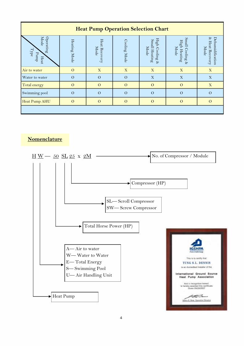
Nomenclature
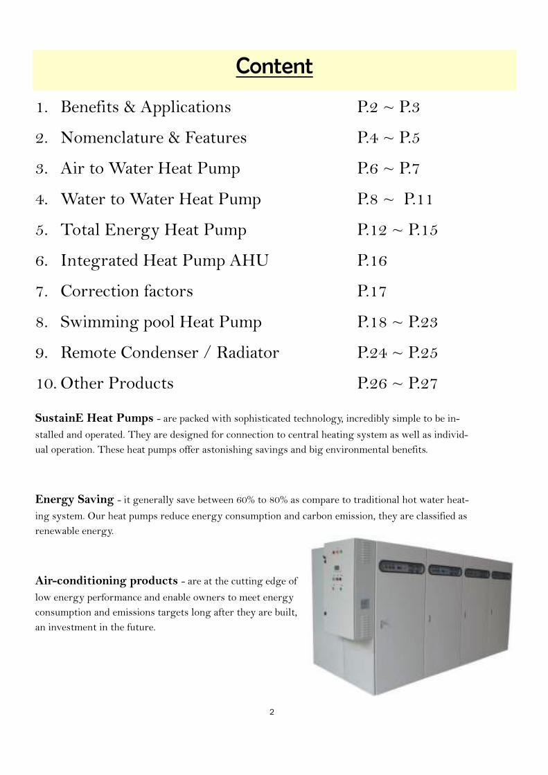
Heat Pump Operation Selection Chart
Heat
Pu
mp
Ty
pe
Op
erating
Mod
e
Heatin
g M
od
e
Heat R
ecov
ery
Mod
e
Coolin
g M
od
e
Hig
h C
oolin
g &
Sm
all Heatin
g
Mod
e
Sm
all Coolin
g &
Hig
h H
eating
Mod
e
Deh
um
idificatio
n
& H
eat Reco
very
Mod
e
Air to water O X X X X X
Water to water O O O X X X
Total energy O O O O O X
Swimming pool O O O O O O
Heat Pump AHU O O O O O O
H W — 50 SL 25 x 2M
A— Air to water
W— Water to Water
E— Total Energy
S— Swimming Pool
U— Air Handling Unit
Compressor (HP)
No. of Compressor / Module
SL— Scroll Compressor
SW— Screw Compressor
Total Horse Power (HP)
Heat Pump

5
Features
High efficiency compressors
All units are equipped with high efficiency scroll or screw compressors, with
R407C, R134a, R410a or R404a to cope with environmental regulations. Re-
frigerant circuits are designed to guarantee reliable system operation.
Intelligent Control System
Electronic controller and microprocessor
provide maximum system performance.
Field connection to BMS or CCMS system
are available for integration to building sys-
tems.
Modular design reduce installation space
Small modular racking design allows for multiple unit installation, require less space in tight location. Cabinet is con-
structed of heavy gauge galvanized sheet metal and coated with corrosion resistive powder paint.
Safety protection
Safety devices are built into the refrigeration circuit to guard against abnormal unit operation. Com-pressor overload protection, high and low pressure cutout switches. Low water temperature sensor is located at the cooler to protect the heat exchanger from freezing. Each compressor is protected by individual branch fusing. Additional protection is provided by thermal overloads, high discharged gas temperature switch. Suction and discharge maintenance valves are provided for manifold gauge con-nections to facilitate servicing. Compressors are mounted on vibration isolators.
Double skin hot water heat exchanger (Selectable option)
Double wall hot water heat exchanger is being used in application with particularly
stringent safety requirements, e.g. food & pharmaceutical. In the event of a leak, water
or refrigerant seeps out between the vented double walls to the atmosphere, thus
gives visual alarm for attention.
ISO 9001:2000
Quality control is the highest priority
in our management objectives. We
ensure good quality through imple-
mentation of ISO procedures. All
units are tested to standard in every
process of manufacturing.
Features
· Cost saving in operation.
· Longer life span of unit can be expected.
· Simple installation, (optional) built-in water pumps can be pro-
vided.
· High COP.
· Less emission of waste heat and CO2, reduce global warming.

6
Air to Water Heat Pump
Air Source Heat Pumps absorb heats from the outside air and raise it to a higher temperature, using a process
which is similar to a reverse refrigeration process. Air Source Heat Pumps can be used in many more applica-
tions including large commercial projects, swimming pools, sports utilities, hotels, club house, SPA, health
care facilities, schools, apartments and food industry. Air Source Heat Pump run on electricity, it helps pre-
vent global warming because no wasted heat discharged to outdoor as compare to gas or oil boilers.
Air Source Heat Pumps can be add-on as supplementary source of heat to pre-heat water before enter to ex-
isting gas or oil boilers. They can also be used in commercial building to recover heat from exhaust air, or as
a dehumidifier to remove moisture in indoor swimming pool, and transfer the recovered heat to incoming
fresh air or hot water.
Exhaust (ventilation) air is a common heat source for heat pumps in residential and commercial buildings.
The Heat Pump recovers heat from the ventilation air, and provides water and/or space heating. For large
buildings exhaust air heat pumps are often used in combination with air-to-air heat recovery.
7
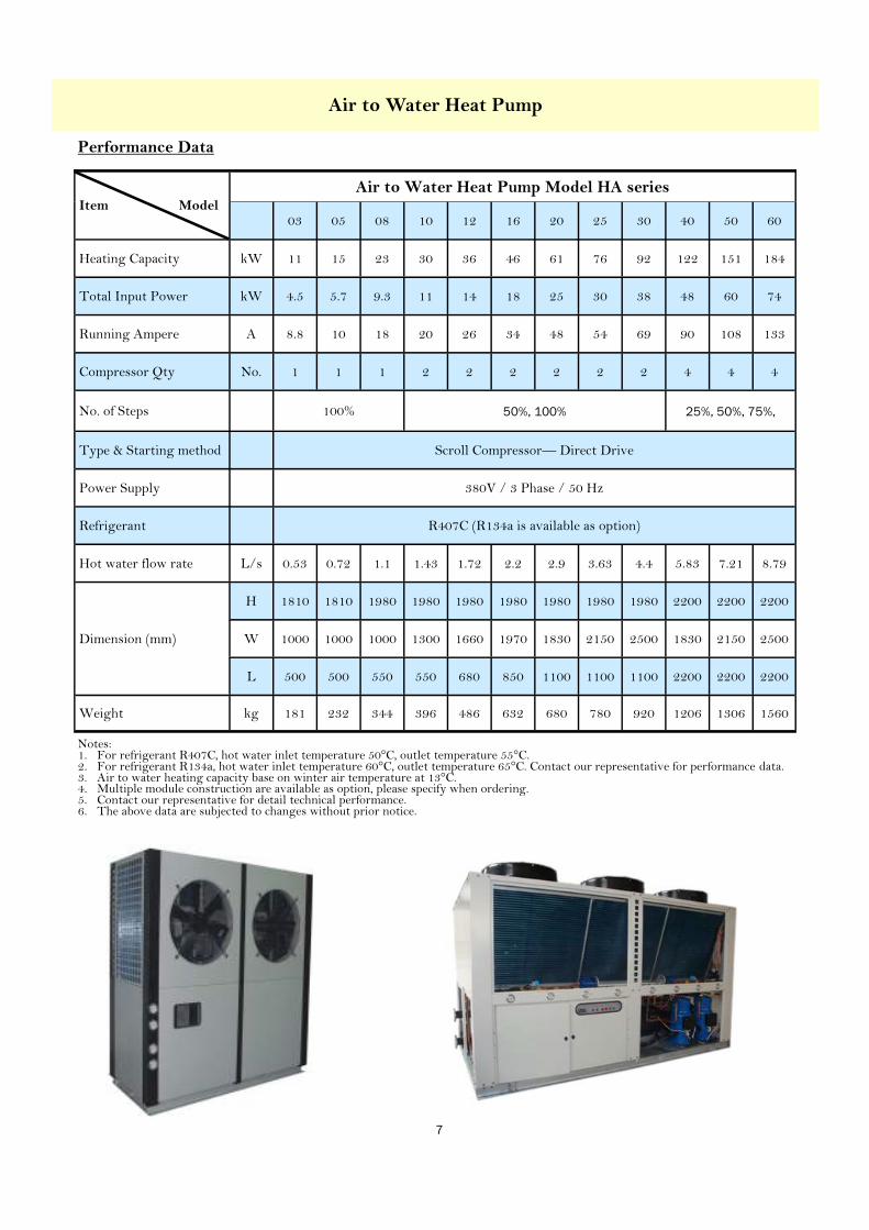
Item Model
Air to Water Heat Pump Model HA series
03 05 08 10 12 16 20 25 30 40 50 60
Heating Capacity kW 11 15 23 30 36 46 61 76 92 122 151 184
Total Input Power kW 4.5 5.7 9.3 11 14 18 25 30 38 48 60 74
Running Ampere A 8.8 10 18 20 26 34 48 54 69 90 108 133
Compressor Qty No. 1 1 1 2 2 2 2 2 2 4 4 4
No. of Steps 100% 50%, 100% 25%, 50%, 75%,
Type & Starting method Scroll Compressor— Direct Drive
Power Supply 380V / 3 Phase / 50 Hz
Refrigerant R407C (R134a is available as option)
Hot water flow rate L/s 0.53 0.72 1.1 1.43 1.72 2.2 2.9 3.63 4.4 5.83 7.21 8.79
Dimension (mm)
H 1810 1810 1980 1980 1980 1980 1980 1980 1980 2200 2200 2200
W 1000 1000 1000 1300 1660 1970 1830 2150 2500 1830 2150 2500
L 500 500 550 550 680 850 1100 1100 1100 2200 2200 2200
Weight kg 181 232 344 396 486 632 680 780 920 1206 1306 1560
Air to Water Heat Pump
Performance Data
Notes: 1. For refrigerant R407C, hot water inlet temperature 50°C, outlet temperature 55°C. 2. For refrigerant R134a, hot water inlet temperature 60°C, outlet temperature 65°C. Contact our representative for performance data. 3. Air to water heating capacity base on winter air temperature at 13°C. 4. Multiple module construction are available as option, please specify when ordering. 5. Contact our representative for detail technical performance. 6. The above data are subjected to changes without prior notice.

8
Water to Water Heat Pumps (Water Source Heat Pump)
Cooling and heating account for more than 60% of the energy used in building, make it the largest energy expense for
most owners. A Water to Water Heat Pump provides both cooling and heating and offer the most benefit of delivering
more useful energy than consume.
The Water to Water Heat Pump contains a source-side water-to-refrigerant heat exchanger (evaporator), and a load-
side refrigerant-to-water (condenser) heat exchanger. The source-side is typically connected to the central air-
conditioning system (chilled water) and the load-side connected to the hot water system. During the refrigerant cycle,
heat is transferred from the source-side heat exchanger to the load-side heat exchanger. The source-side provides
chilled water to central air-conditioning plant for cooling and simultaneously the load-side provides hot water to the
domestic hot water system or pool water heating.
Water to Water Heat Pump make use of the building cooling load as a heat source for hot water heating, it reclaim the
heat instead of reject to outdoor, thus achieves added efficiency, energy saving and kind to the environment.
Many industries need space cooling in their process, and often have a significant hot water demand in the temperature
range from 40~65 degree C for washing, sanitation and cleaning purpose. Water to Water Heat Pump can be a part of
an integrated system that provides both cooling and heating.
Water to Water Heat Pump meets space cooling and hot water heating in building, typical applications include large
hotels, sports utilities, club house, SPA, health care facilities, and food industry.
Water to Water Heat Pump

9
Water to Water Heat Pump
Performance Data
Item Model
Water to Water Heat Pump Model HW series
SL08 SL10 SL12 SL15 SL20 SL25
R134 R407 R134 R407 R134 R407 R134 R407 R134 R407 R134 R407
Heating Capacity kW 16 23 20 30 26 37 31 45 41 62 51 76
Cooling Capacity kW 9 15 12 20 15 24 18 30 24 41 30 51
Total Input Power kW 7 8 9 10 11 13 13 15 17 21 21 25
Running Ampere A 12.3 13.7 16.0 18.3 19.3 21.1 22.6 26.5 28.6 34.1 36.4 41.2
Compressor Qty No. 1 1 1 1 1 1 1 1 1 1 1 1
No. of Steps No. 1 1 1 1 1 1 1 1 1 1 1 1
Type & Starting method Scroll Compressor— Direct Drive
Power Supply 380V / 3 Phase / 50 Hz
Refrigerant R134a (R407C is available as option)
Hot water flow rate L/s 0.75 1.07 0.97 1.43 1.22 1.77 1.46 2.15 1.96 2.94 2.45 3.63
Chilled water flow rate L/s 0.43 0.70 0.56 0.94 0.70 1.17 0.86 1.42 1.16 1.96 1.45 2.43
Dimension (mm)
H 1600 1600 1600 1600 1600 1600 1600 1600 1800 1800 1800 1800
W 610 610 610 610 610 610 610 610 752 752 752 752
L 1400 1400 1400 1400 1400 1400 1400 1400 1600 1600 1600 1600
Weight kg 265 265 326 326 387 387 489 489 557 557 625 625
Notes: 1. For refrigerant R407C, hot water inlet temperature 50°C, outlet temperature 55°C. 2. For refrigerant R134a, hot water inlet temperature 60°C, outlet temperature 65°C. 3. For both R407C and R134a, chilled water inlet temperature at 12°C, outlet temperature at 7°C. 4. Contact our representative for detail technical performance. 5. The above data are subjected to changes without prior notice.

10
Water to Water Heat Pump
Model No. of Modules
Multiple Module Performance Data Model HW series (R134a)
1M 2M 3M 4M 5M 6M 7M 8M
SL08
Heating Capacity (kW) 16 32 48 64 80 96 112 128
Cooling Capacity (kW) 9 18 27 36 45 54 63 72
Total Input Power (kW) 7 14 21 28 35 42 49 56
SL10
Heating Capacity (kW) 20 40 60 80 100 120 140 160
Cooling Capacity (kW) 12 24 36 48 60 72 84 96
Total Input Power (kW) 9 18 27 36 45 54 63 72
SL12
Heating Capacity (kW) 26 52 78 104 130 156 182 208
Cooling Capacity (kW) 15 30 45 60 75 90 105 120
Total Input Power (kW) 11 22 33 44 55 66 77 88
SL15
Heating Capacity (kW) 31 62 93 124 155 186 217 248
Cooling Capacity (kW) 18 36 54 72 90 108 126 144
Total Input Power (kW) 13 26 39 52 65 78 91 104
SL20
Heating Capacity (kW) 41 82 123 164 205 246 287 328
Cooling Capacity (kW) 24 48 72 96 120 144 168 192
Total Input Power (kW) 17 34 51 68 85 102 119 136
SL25
Heating Capacity (kW) 51 102 153 204 255 306 357 408
Cooling Capacity (kW) 30 60 90 120 150 180 210 240
Total Input Power (kW) 21 42 63 84 105 126 147 168
Notes: 1. For refrigerant R407C, hot water inlet temperature 50°C, outlet temperature 55°C. 2. For refrigerant R134a, hot water inlet temperature 60°C, outlet temperature 65°C. 3. For both R407C & R134a, chilled water inlet temperature at 12°C, outlet temperature at 7°C. 4. Multiple module performance data for R407C can be provided upon request. 5. Contact our representative for detail technical performance. 6. The above data are subjected to changes without prior notice.
Performance Data

11
Water to Water Heat Pump
Performance Data
Item Model
Water to Water Heat Pump Model HW series
SW75 SW81 SW93 SW113 SW110 SW150 SW162 SW186 SW226
Heating Capacity kW 177 204 221 278 266 355 408 442 555
Cooling Capacity kW 104 120 132 167 158 208 240 264 334
Total Input Power kW 73 84 89 111 108 145 168 177 222
Running Ampere A 131 142 188 200 192 262 142 188 200
Compressor Qty No. 1 1 1 1 2 2 2 2 2
No. of Steps No. 3 3 3 3 4 4 4 4 4
Type & Starting method Screw Compressor
Power Supply 380V / 3 Phase / 50 Hz
Refrigerant R134a (R407C is available as option)
Hot water flow rate L/s 8.4 9.1 9.8 12.3 11.8 15.8 18.1 19.6 24.7
Chilled water flow rate L/s 4.6 5.3 5.8 7.4 7.0 9.2 10.6 11.7 14.8
Dimension (mm)
H 1800 1900 2100 2100 1800 1900 1900 2100 2100
W 2500 2500 2850 2850 2850 2850 2950 2950 3300
L 900 900 1000 1000 1500 1500 1500 1700 1700
Weight kg 1550 1830 1890 2200 2250 2500 3330 3880 4280
Notes: 1. Hot water inlet temperature 50°C, outlet temperature 55°C. For refrigerant R407C. 2. Hot water inlet temperature 60°C, outlet temperature 65°C. For refrigerant R134a. 3. Chilled water inlet temperature at 12°C, outlet temperature at 7°C. 4. Contact our representative for detail technical performance. 5. The above data are subjected to changes without prior notice.
12
Total Energy Heat Pump
Total Energy Heat Pump
A Total Energy Heat Pump is a combination of Air Source Heat Pump and Water Source Heat Pump, it serve as a nor-
mal air cooled chiller unit and hot water heat pump as well. Total Energy Heat Pump is capable to produce chilled wa-
ter and hot water to meet both the cooling and heating demand simultaneously for the air-conditioning system and hot
water system.
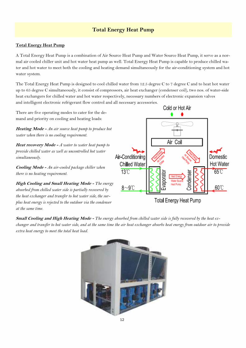
The Total Energy Heat Pump is designed to cool chilled water from 12.5 degree C to 7 degree C and to heat hot water
up to 65 degree C simultaneously, it consist of compressors, air heat exchanger (condenser coil), two nos. of water-side
heat exchangers for chilled water and hot water respectively, necessary numbers of electronic expansion valves
and intelligent electronic refrigerant flow control and all necessary accessories.
There are five operating modes to cater for the de-
mand and priority on cooling and heating loads:
Heating Mode - An air source heat pump to produce hot
water when there is no cooling requirement.
Heat recovery Mode - A water to water heat pump to
provide chilled water as well as uncontrolled hot water
simultaneously.
Cooling Mode - An air-cooled package chiller when
there is no heating requirement.
High Cooling and Small Heating Mode - The energy
absorbed from chilled water side is partially recovered by
the heat exchanger and transfer to hot water side, the sur-
plus heat energy is rejected to the outdoor via the condenser
at the same time.
Small Cooling and High Heating Mode - The energy absorbed from chilled water side is fully recovered by the heat ex-
changer and transfer to hot water side, and at the same time the air heat exchanger absorbs heat energy from outdoor air to provide
extra heat energy to meet the total heat load.
13
Total Energy Heat Pump
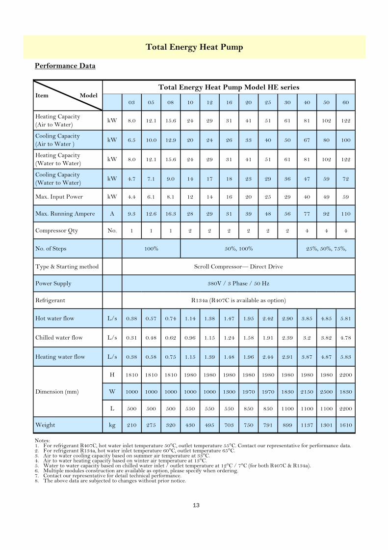
Item Model
Total Energy Heat Pump Model HE series
03 05 08 10 12 16 20 25 30 40 50 60
Heating Capacity
(Air to Water) kW 8.0 12.1 15.6 24 29 31 41 51 61 81 102 122
Cooling Capacity
(Air to Water ) kW 6.5 10.0 12.9 20 24 26 33 40 50 67 80 100
Heating Capacity
(Water to Water) kW 8.0 12.1 15.6 24 29 31 41 51 61 81 102 122
Cooling Capacity
(Water to Water) kW 4.7 7.1 9.0 14 17 18 23 29 36 47 59 72
Max. Input Power kW 4.4 6.1 8.1 12 14 16 20 25 29 40 49 59
Max. Running Ampere A 9.3 12.6 16.3 28 29 31 39 48 56 77 92 110
Compressor Qty No. 1 1 1 2 2 2 2 2 2 4 4 4
No. of Steps 100% 50%, 100% 25%, 50%, 75%,
Type & Starting method Scroll Compressor— Direct Drive
Power Supply 380V / 3 Phase / 50 Hz
Refrigerant R134a (R407C is available as option)
Hot water flow L/s 0.38 0.57 0.74 1.14 1.38 1.47 1.95 2.42 2.90 3.85 4.85 5.81
Chilled water flow L/s 0.31 0.48 0.62 0.96 1.15 1.24 1.58 1.91 2.39 3.2 3.82 4.78
Heating water flow L/s 0.38 0.58 0.75 1.15 1.39 1.48 1.96 2.44 2.91 3.87 4.87 5.83
Dimension (mm)
H 1810 1810 1810 1980 1980 1980 1980 1980 1980 1980 1980 2200
W 1000 1000 1000 1000 1000 1300 1970 1970 1830 2150 2500 1830
L 500 500 500 550 550 550 850 850 1100 1100 1100 2200
Weight kg 210 275 320 430 495 703 750 791 899 1137 1301 1610
Notes: 1. For refrigerant R407C, hot water inlet temperature 50°C, outlet temperature 55°C. Contact our representative for performance data. 2. For refrigerant R134a, hot water inlet temperature 60°C, outlet temperature 65°C. 3. Air to water cooling capacity based on summer air temperature at 33°C. 4. Air to water heating capacity based on winter air temperature at 13°C. 5. Water to water capacity based on chilled water inlet / outlet temperature at 12°C / 7°C (for both R407C & R134a). 6. Multiple modules construction are available as option, please specify when ordering. 7. Contact our representative for detail technical performance. 8. The above data are subjected to changes without prior notice.
Performance Data

14
Total Energy Heat Pump
Performance Data
Item Model
Total Energy Heat Pump Model HE series
03 05 08 10 12 16 20 25 30 40 50 60
Heating Capacity
(Air to Water) kW 9.3 12.6 19.5 25 31 39 52 65 79 104 130 157
Cooling Capacity (9)
(Air to Water ) kW 7.9 11.7 18 23 28 36 48 59 72 96 117 145
Heating Capacity
(Water to Water) kW 10.5 14.4 23 28 35 45 60 74 90 120 148 180
Cooling Capacity (10)
(Water to Water) kW 6.7 9.7 15 20 22 30 39 49 59 79 98 119
Max. Input Power kW 4.8 6.2 10 12 15 19 25 30 38 48 60 74
Max. Running Ampere A 9.8 11.8 20 22 29 37 48 54 69 90 108 133
Compressor Qty No. 1 1 1 2 2 2 2 2 2 4 4 4
No. of Steps 100% 50%, 100% 25%, 50%, 75%,
Type & Starting method Scroll Compressor— Direct Drive
Power Supply 380V / 3 Phase / 50 Hz
Refrigerant R407C
Hot water flow
(Water-water) L/s 0.5 0.7 1.1 1.4 1.7 2.2 2.9 3.5 4.3 5.7 7.1 8.6
Chilled water flow L/s 0.4 0.6 0.9 1.1 1.4 1.7 2.3 2.8 3.5 4.6 5.6 6.9
Heating water flow L/s 0.4 0.6 0.9 1.2 1.5 1.9 2.5 3.1 3.8 5.0 6.2 7.5
Dimension (mm)
H 1810 1810 1980 1980 1980 1980 1980 1980 1980 2200 2200 2200
W 1000 1000 1000 1300 1660 1970 1830 2150 2500 1830 2150 2500
L 500 500 550 550 680 850 1100 1100 1100 2200 2200 2200
Weight kg 227 290 430 495 608 790 850 975 1150 1508 1633 1950
Notes: 1. For refrigerant R407C, hot water inlet temperature 50°C, outlet temperature 55°C. Contact our representative for performance data. 2. For refrigerant R134a, hot water inlet temperature 60°C, outlet temperature 65°C. 3. Air to water cooling capacity based on summer air temperature at 33°C. 4. Air to water heating capacity based on winter air temperature at 13°C. 5. Water to water capacity based on chilled water inlet / outlet temperature at 12°C / 7°C (for both R407C & R134a). 6. Multiple modules construction are available as option, please specify when ordering. 7. Contact our representative for detail technical performance. 8. The above data are subjected to changes without prior notice. 9. For Air cooled chiller, i.e. cooling only no heating function, the model designation is HACH-xx. 10. For Water cooled chiller, i.e. cooling only no heating function, the model designation is HWCH-xx.

15
Total Energy Heat Pump
Performance Data
Item Model
Total Energy Heat Pump Model HE series
70 80 90 100 110 120 130 140 150 160 170 180
Heating Capacity
(Air to Water) kW 183 208 234 259 286 314 338 363 388 416 443 470
Cooling Capacity (9)
(Air to Water ) kW 168 192 213 234 262 289 310 331 352 379 406 434
Heating Capacity
(Water to Water) kW 210 239 267 295 328 360 388 415 443 475 508 540
Cooling Capacity (10)
(Water to Water) kW 138 156 176 195 216 237 255 274 293 314 334 355
Max. Input Power kW 85 96 108 120 134 148 159 170 181 195 208 221
Max. Running Ampere A 156 180 198 216 241 266 286 306 325 350 375 400
Compressor Qty No. 8 8 8 8 8 8 8 8 12 12 12 12
No. of Steps 8 8 8
Type & Starting method Scroll Compressor— Direct Drive
Power Supply 380V / 3 Phase / 50 Hz
Refrigerant R407C
Hot water flow
(Water-water) L/s 10 11.4 12.7 14.1 15.6 17.2 18.4 19.7 21.2 22.6 24.1 25.8
Chilled water flow L/s 8 9.2 10.1 11.2 12.5 13.8 14.8 15.8 16.8 18.0 19.3 20.7
Heating water flow L/s 8.7 9.9 11.1 12.4 13.6 15 16.1 17.3 18.6 19.8 21.1 22.5
Dimension (mm)
H 2200 2200 2200 2200 2200 2200 2200 2200 2200 2200 2200 2200
W 3080 3660 7960 4300 4650 5000 5483 5967 6450 6800 7150 7500
L 2200 2200 2200 2200 2200 2200 2200 2200 2200 2200 2200 2200
Weight kg 2483 3016 3141 3266 7166 3900 4233 4566 4899 5216 5533 5850
Notes: 1. For refrigerant R407C, hot water inlet temperature 50°C, outlet temperature 55°C. Contact our representative for performance data. 2. For refrigerant R134a, hot water inlet temperature 60°C, outlet temperature 65°C. 3. Air to water cooling capacity based on summer air temperature at 33°C. 4. Air to water heating capacity based on winter air temperature at 13°C. 5. Water to water capacity based on chilled water inlet / outlet temperature at 12°C / 7°C (for both R407C & R134a). 6. Multiple modules construction are available as option, please specify when ordering. 7. Contact our representative for detail technical performance. 8. The above data are subjected to changes without prior notice. 9. For Air cooled chiller, i.e. cooling only no heating function, the model designation is HACH-xx. 10. For Water cooled chiller, i.e. cooling only no heating function, the model designation is HWCH-xx.

16
Integrated Heat Pump - Air Handling Unit
Roof Cover of outdoor
application (option)
DX cooling coil
Optional Heating coil(water)
Refrigerant pipe(Field Install)
Hot Water Out
Hot Water In
Optimization of cool air and hot water
SustainE Heat Pump Air Handle Unit recovers heat from air conditioning system application. Air side application can be
indoor air-conditioning Air Handling Unit or fresh air intake pre-treat Primary Air Handling Unit. Floor mount type and
ceiling mount type are available for selection. Please contact our representative for more detail.
Ceiling-mount type
Floor-mount type
Chilled water In/out
Hot water In/out
Notes :
1. External static pressure requirement to be specified by client.
2. Please contact our representative for detail technical data sheet.
Heat Pump Air Handling Unit Model HU Series Item
Model
5 8 10 12 16 20 25 30 40 50 60
Cooling Capacity kW 9 11 18 21 23 30 37 45 59 74 91
Heating Capacity kW 14 18 28 34 36 47 59 71 94 117 142
Total Input Power kW 5 8 12 14 16 20 25 29 40 49 58
Air Flow L/s 450 550 860 1050 1100 1440 1800 2200 2870 3570 4360

17
Correction factor at other operating conditions
Water to water Heat Pump correction factors
10°C 11°C 12°C 13°C 14°C 15°C
Hot
water
outlet tem-
Chilled water
inlet tem-Cooling Heating Cooling Heating Cooling Heating Cooling Heating Cooling Heating Cooling Heating
Heat pump with R134a refrigerant
40°C 1.39 1.05 1.45 1.08 1.52 1.12 1.54 1.15 1.65 1.19 1.71 1.23
45°C 1.30 1.03 1.36 1.06 1.42 1.09 1.48 1.13 1.54 1.16 1.61 1.20
50°C 1.21 1.00 1.26 1.04 1.32 1.07 1.38 1.10 1.44 1.14 1.50 1.17
55°C 1.12 0.99 1.16 1.01 1.22 1.04 1.27 1.08 1.32 1.11 1.38 1.14
60°C 1.00 0.97 1.06 1.00 1.11 1.02 1.16 1.05 1.21 1.08 1.26 1.11
65°C 0.91 0.95 0.95 0.98 1.00 1.00 1.04 1.02 1.09 1.06 1.15 1.08
Heat pump with R407C refrigerant
40°C 1.17 1.02 1.22 1.05 1.27 1.08 1.33 1.12 1.38 1.15 1.43 1.19
45°C 1.09 0.99 1.14 1.02 1.19 1.05 1.24 1.09 1.29 1.12 1.34 1.15
50°C 1.01 0.97 1.05 1.00 1.09 1.03 1.14 1.06 1.19 1.09 1.24 1.12
55°C 0.92 0.95 0.96 0.97 1.00 1.00 1.04 1.03 1.09 1.06 1.13 0.99
Air to water Heat Pump correction factors
Hot water outlet temperature Type of
40°C 45°C 50°C 55°C 60°C 65°C
R134a 1.12 1.09 1.07 1.04 1.02 1.00
R407C 1.08 1.05 1.03 1.00 — —
Cooling / heating capacity at other conditions
= Nominal capacity x Correction factor

18
Swimming Pool Heat Pump
FEATURES
Refrigeration design
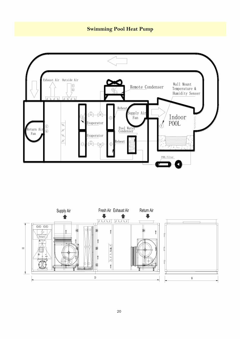
Dual refrigerant circuit design allows staging to minimize energy consumption and optimize energy recovery. The system combines of air coiling coils, reheat coils, water (pool) condensers or remote condensers. Circuit “A” recovers the energy to the air or water, it balance the heat lost due to evaporation on water surface. Circuit “B” allows the system to recover energy, or absorb heat from ambient and deliver it to the space in the winter but reject the heat for cooling in the summer.
The dual circuit design provides simultaneous recovery of heat to water and air, its independent refrigerant circuit provide versatile capability to control indoor air quality accurately.
DX Cooling / Reheat Coils
All cooling and reheat air coils have a specifically designed epoxy coat or E-coat to protect Aluminum and copper surfaces. As unprotected coils corrodes, heat transfer capacity diminished and cooling capacity reduced, extend maintenance time is required to repair the system. Coils are pro-tected from corrosion without affecting heat transfer, is ideal for applica-tion in environments with a high chloramines compounds, hazardous commercial areas and industrial sites.
Condensers (refrigerant to water heat exchangers)
All condensers are chemically cleanable. Condensers are coaxial tube-in-tube or shell and tube type for maximum heat transfer effi-ciency and performance. Inner water tubes are either Cupro-nickel or Titanium (selectable option) with large internal diameters for reduced water-side pressure drops. Double skin inner tube are available as option. Outer tubes or shell are steel, painted for corro-sion protection.
Filters
All units come with standard 25mm thick efficiency washable filters. Optional filters are available. Filters are removable from the sides of the frames through filter access panels.
Cooling or Heating Water Coils (Optional)
When chilled water or hot water is available, water coils can be factory-installed upstream of the supply fan. The coil has a factory-installed and wired three-way flow control valve and is controlled by the unit’s control system.
Casing and Framework
Heavy-duty structural support with Aluminum alloy framework. All metal frame and panels use a spe-cial corrosion resisting galvanize steel with a powder coat finish on exterior, a tough coating that resists rusting.
The frameworks are designed for ease of disassembly and re-assembly. All panels are insulated with 50mm thick high density PU insulation for thermal and acoustic per-formance.
All components are located for ease of inspection and service. Major components are out of the unit’s air stream to allow maintenance while the unit is in operation. Service access is through the removal of access panels located on the unit.
All refrigerant components are accessible from the front of the unit for service and maintenance.
The unit can be installed either indoors or outdoors. Units intended for outdoor installation are factory equipped with additional cover, heavy duty weather sealing.
19
Swimming Pool Heat Pump
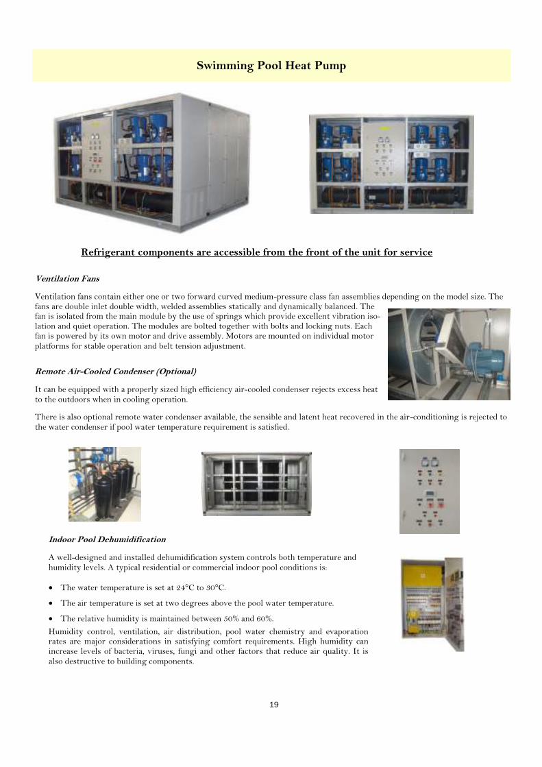
Ventilation Fans
Ventilation fans contain either one or two forward curved medium-pressure class fan assemblies depending on the model size. The fans are double inlet double width, welded assemblies statically and dynamically balanced. The fan is isolated from the main module by the use of springs which provide excellent vibration iso-lation and quiet operation. The modules are bolted together with bolts and locking nuts. Each fan is powered by its own motor and drive assembly. Motors are mounted on individual motor platforms for stable operation and belt tension adjustment.
Remote Air-Cooled Condenser (Optional)
It can be equipped with a properly sized high efficiency air-cooled condenser rejects excess heat to the outdoors when in cooling operation.
There is also optional remote water condenser available, the sensible and latent heat recovered in the air-conditioning is rejected to the water condenser if pool water temperature requirement is satisfied.
Indoor Pool Dehumidification
A well-designed and installed dehumidification system controls both temperature and humidity levels. A typical residential or commercial indoor pool conditions is:
· The water temperature is set at 24°C to 30°C.
· The air temperature is set at two degrees above the pool water temperature.
· The relative humidity is maintained between 50% and 60%.
Humidity control, ventilation, air distribution, pool water chemistry and evaporation rates are major considerations in satisfying comfort requirements. High humidity can increase levels of bacteria, viruses, fungi and other factors that reduce air quality. It is also destructive to building components.
Refrigerant components are accessible from the front of the unit for service
20
Swimming Pool Heat Pump
21
Swimming Pool Heat Pump
Dehumidification and Reheat
This is the basic option which removes moisture from the air at the evaporator coil and reheats it before returning to the space as dehumidified air.
Dehumidification, Reheat & Water heating (pool)
Instead of rejecting the heat to the reheat coil, the three-way valve on one refrigerant circuit divert hot gas to the water con-densing coil to reject heat to the pool water. Either circuit can become the primary heat sink allowing the circuit’s latent and sensible heat to be directed to a water source or returned to the air.
Air-conditioning & Remote condenser
This is very similar to the dehumidification & reheat, instead of sending recovered energy to a reheat coil, the energy is rejected to an outdoor condenser.
Dehumidification, Air-conditioning & Remote condenser
This is the combination of all heat sink options. It is used when only a partial water heat sink is available but full capacity dehu-midification is required continuously, regardless of season.
Air Source Heat Pump in cold weather (selectable option)
Even though recovered energy is sent to the space during the dehumidification process, the heat loss of the space can be greater in cold weather. Auxiliary heating may be required. One of the refrigerant circuits can be operated as an Air Source Heat Pump to provide efficiency heat energy to complete indoor cli-mate control in one package. More than 60% saving in operation cost during cold season can be obtained as compared to auxiliary electrical heating elements.
Auxiliary chilled / hot water coil control
The unit controller will send a 0-10V (or other variable control voltage) to a modulating control valve. The function of the coils shall be clearly specified by the client. The unit controller will modulate the water coil valves as the specified by client. The control valve is supplied and installed by others.
Ventilation
Every indoor swimming pool requires the introduction of out-door ventilation air during occupied times. The unit offers (optional) variable speed drive fans to integrate ventilation air into the dehumidification package. The dehumidifier blower will act as the ventilation fan and supply air blower. The unit con-troller can reduce fan speed to save energy when the occupancy level of the swimming pool is low.
The ventilation system simplifies air balancing while maintain-ing the correct proportions of return air, supply air, exhaust air and outdoor air.
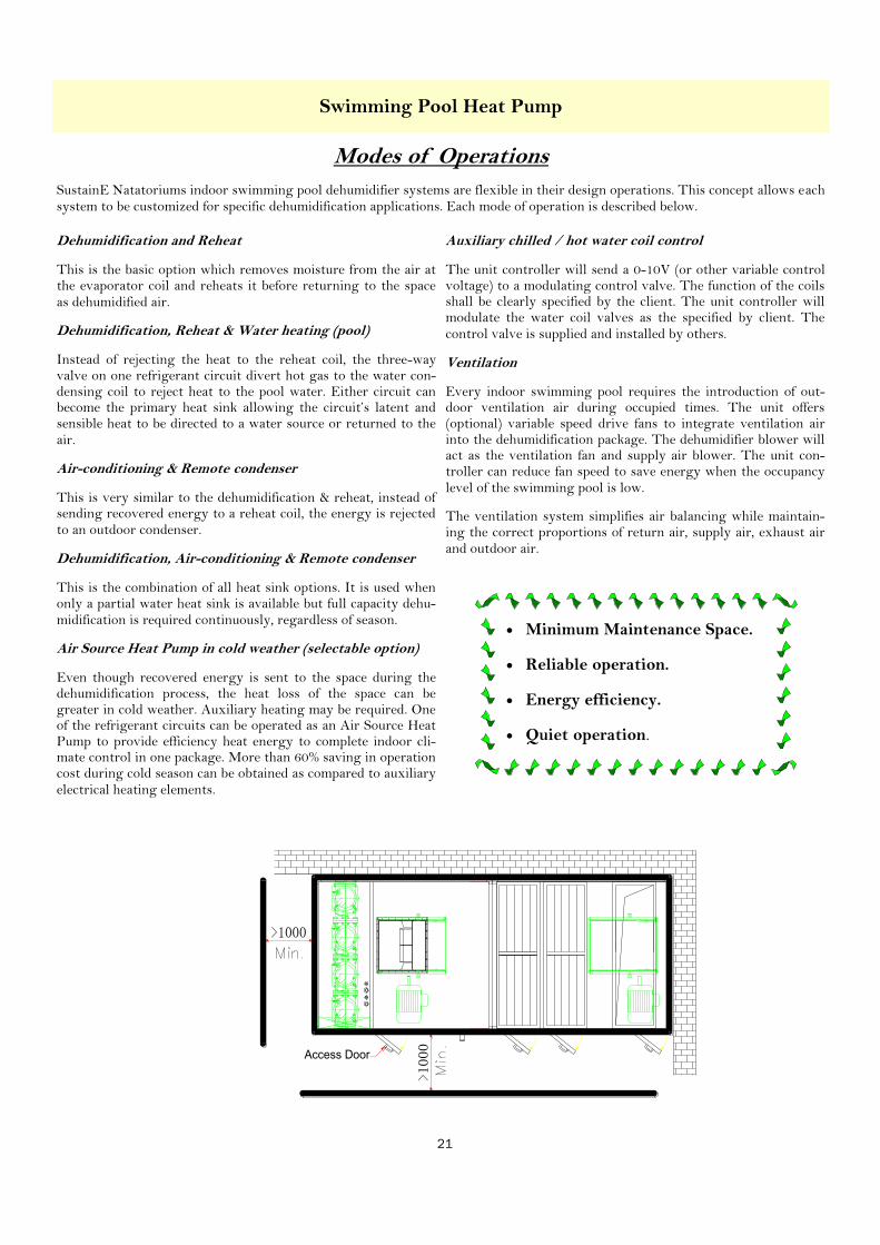
Access Door
· Minimum Maintenance Space.
· Reliable operation.
· Energy efficiency.
· Quiet operation.
Modes of Operations
SustainE Natatoriums indoor swimming pool dehumidifier systems are flexible in their design operations. This concept allows each system to be customized for specific dehumidification applications. Each mode of operation is described below.

22
Swimming Pool Heat Pump
Item Model Swimming Pool Heat Pump HS series
30 40 50 60 70 80 100 120
Air Cooling Capacity kW 88 117 143 176 214 241 295 361
Air Heating Capacity kW 97 128 157 193 235 263 324 395
Water Heating Capacity kW 147 195 238 294 357 401 493 601
Dehumidification Kg/h 51 67 82 101 123 138 169 206
Total Input Power kW 36 47 62 71 90 98 120 145
Running Ampere A 68 93 116 135 163 173 221 259
Capacity Steps Nos. 50%, 100% 25%, 50%, 75%, 100%
Compressor Qty Nos. 2 4 4 4 6 4 4 6
Type & Starting Method Scroll Compressor with Direct Drive
Refrigerant R407C (R134a is available in option)
Supply Air Fan Centrifugal Double Inlet
Supply Air Flow M³/h 13068 17280 21096 26064 31644 35568 43632 53316
E.S.P. Pa 300 550 550 550 550 550 550 550
Supply Fan Motor kW 5.5 7.5 11 11 15 15 18.5 22
Return Air Fan Centrifugal Double Inlet
Return Air Flow M³/h 13068 17280 21096 26064 31644 35568 43632 53316
E.S.P. Pa 300 550 550 550 550 550 550 550
Return Fan Motor kW 5.5 7.5 11 11 15 15 18.5 22
Desuperheater type Shell & Tube, plate or co-axial {Cupro-nickel or Titanium (optional)}
Hot Water Flow L/s 7.0 9.3 11.4 14.1 17.1 19.2 23.6 28.7
Power Supply 380V / 3 Phase / 50 Hz
Performance Data
Note:
1. Air entering temperature at evaporator coil is 28°C 60% RH; outdoor air temperature at 35°C.
2. Please specify hot water heat exchanger (De-superheater) material when ordering.
3. Performance data for R134a to be provided on request.
4. Other models are available, please contact our representative for information.
5. Remote condensers are available as option, please specify when ordering.
23
Swimming Pool Heat Pump
Humidity and moisture of indoor pools
Effective control of indoor pool humidity help prevent bacteria, viruses, fungi and protect building components. The
amount of water evaporated from an indoor swimming pool depends on:
1. The surface area of the swimming pool.
2. The water temperature of the swimming pool.
3. The indoor air temperature and relative humidity.
4. The air velocity over water surface.
Calculation of dehumidification requirement based on water evaporation rate from ASHRAE APPLICATION HAND-
BOOK.
(The following sections are relevant extraction from ASHRAE handbook - Nataoriums)
Internal latent loads are generally from people and evaporation. Evaporation loads in pools are significant relative to
other load elements and may vary widely depending on pool features, areas of water and wet deck, water temperature,
and activity level in the pool.
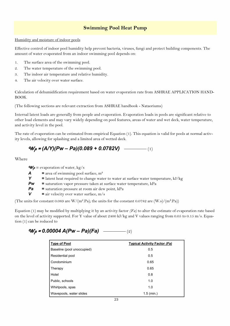
The rate of evaporation can be estimated from empirical Equation (1). This equation is valid for pools at normal activ-
ity levels, allowing for splashing and a limited area of wetted deck.
Wp = (A/Y)(Pw – Pa)(0.089 + 0.0782V) ————— (1)
Where
Wp = evaporation of water, kg/s
A = area of swimming pool surface, m²
Y = latent heat required to change water to water at surface water temperature, kJ/kg
Pw = saturation vapor pressure taken at surface water temperature, kPa
Pa = saturation pressure at room air dew point, kPa
V = air velocity over water surface, m/s
(The units for constant 0.089 are W/(m².Pa); the units for the constant 0.0782 are (W.s)/(m .Pa))
Equation (1) may be modified by multiplying it by an activity factor (Fa) to alter the estimate of evaporation rate based
on the level of activity supported. For Y value of about 2400 kJ/kg and V values ranging from 0.05 to 0.15 m/s. Equa-
tion (1) can be reduced to
Wp = 0.00004 A(Pw – Pa)(Fa) ————— (2)
Type of Pool Typical Activity Factor (Fa)
Baseline (pool unoccupied) 0.5
Residential pool 0.5
Condominium 0.65
Therapy 0.65
Hotel 0.8
Public, schools 1.0
Whirlpools, spas 1.0
Wavepools, water slides 1.5 (min.)

24
Remote Condenser
Model HACU
-15S
HACU
-20D
HACU
-25D
HACU
-30D
HACU
-40F
HACU
-50F
HACU
-60F
HACU
-80F
Heat Rejection kW 56 76 92 112 152 184 224 308
Electrical 380V / 3 / 50 Hz
Refrigerant R407C (R134a available as option)
Ventilator Fan Type Propeller
Input KW 1.05 0.88x2 0.88x2 1.05x2 0.88x4 0.88x4 1.05x4 0.88x8
Dimension
W ‘mm 1500 1830 2150 2500 1830 2150 2500 3200
D ‘mm 1100 1100 1100 1100 2200 2200 2200 2200
H ‘mm 1250 1250 1250 1250 1250 1250 1250 1250
Weight kg 378 420 480 720 1050 1380 1800 2220
Performance data
Note :
1. Please contact our representative for detail technical data sheet.

25
Model HAC-150 HAC-200 HAC-240 HAC-280 HAC-320
Heat Rejection kW 151 205 243 280 325
Electrical 380V / 3 / 50 Hz
Fluid type Water
Ventilator Fan Type Propeller / Axial (Static Pressure 50~300Pa)
Input KW 4.0x3 5.5x3 5.5x3 5.5x4 5.5x4
Dimension
W ‘mm 3000 3500 4000 5000 6000
D ‘mm 1500 1500 1500 1500 1500
H ‘mm 2000 2000 2000 2000 2000
Weight kg 2130 2500 2830 3275 3680
Remote Radiator

26
Other Products
Air to Air Heat Pumps
DX Air-Conditioning
Air Handling Units
27
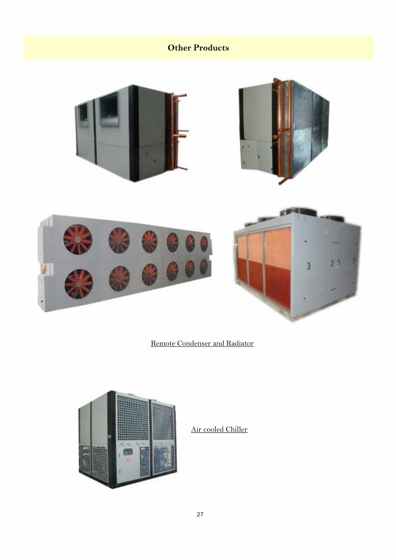
Remote Condenser and Radiator
Air cooled Chiller
Other Products