Embed Size (px)
Citation preview
V
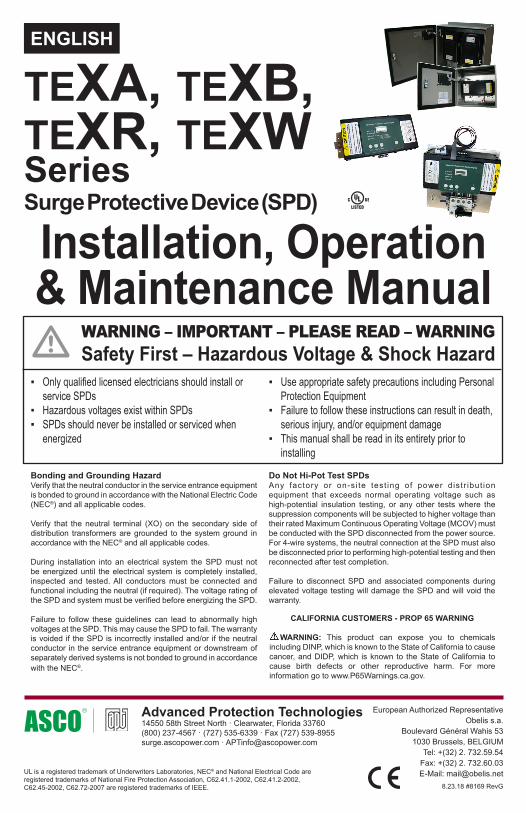
Installation, Operation & Maintenance Manual
UL is a registered trademark of Underwriters Laboratories, NEC® and National Electrical Code are registered trademarks of National Fire Protection Association, C62.41.1-2002, C62.41.2-2002, C62.45-2002, C62.72-2007 are registered trademarks of IEEE.
ENGLISH
Surge Protective Device (SPD)
Bonding and Grounding HazardVerify that the neutral conductor in the service entrance equipment is bonded to ground in accordance with the National Electric Code (NEC®) and all applicable codes.
Verify that the neutral terminal (XO) on the secondary side of distribution transformers are grounded to the system ground in accordance with the NEC® and all applicable codes.
During installation into an electrical system the SPD must not be energized until the electrical system is completely installed, inspected and tested. All conductors must be connected and functional including the neutral (if required). The voltage rating of the SPD and system must be verified before energizing the SPD.
Failure to follow these guidelines can lead to abnormally high voltages at the SPD. This may cause the SPD to fail. The warranty is voided if the SPD is incorrectly installed and/or if the neutral conductor in the service entrance equipment or downstream of separately derived systems is not bonded to ground in accordance with the NEC®.
Safety First – Hazardous Voltage & Shock HazardWARNING – IMPORTANT – PLEASE READ – WARNING
▪ Only qualified licensed electricians should install or service SPDs
▪ Hazardous voltages exist within SPDs ▪ SPDs should never be installed or serviced when
energized
Do Not Hi-Pot Test SPDsAny factory or on-si te test ing of power distr ibut ion equipment that exceeds normal operating voltage such as high-potential insulation testing, or any other tests where the suppression components will be subjected to higher voltage than their rated Maximum Continuous Operating Voltage (MCOV) must be conducted with the SPD disconnected from the power source. For 4-wire systems, the neutral connection at the SPD must also be disconnected prior to performing high-potential testing and then reconnected after test completion.
Failure to disconnect SPD and associated components during elevated voltage testing will damage the SPD and will void the warranty.
TEXA, TEXB,TEXR, TEXWSeries
8.23.18 #8169 RevG
European Authorized RepresentativeObelis s.a.
Boulevard Général Wahis 531030 Brussels, BELGIUM
Tel: +(32) 2. 732.59.54Fax: +(32) 2. 732.60.03E-Mail: [email protected]
Advanced Protection Technologies 14550 58th Street North · Clearwater, Florida 33760(800) 237-4567 · (727) 535-6339 · Fax (727) 539-8955surge.ascopower.com · [email protected]
▪ Use appropriate safety precautions including Personal Protection Equipment
▪ Failure to follow these instructions can result in death, serious injury, and/or equipment damage
▪ This manual shall be read in its entirety prior to installing
CALIFORNIA CUSTOMERS - PROP 65 WARNING
WARNING: This product can expose you to chemicals including DINP, which is known to the State of California to cause cancer, and DIDP, which is known to the State of California to cause birth defects or other reproductive harm. For more information go to www.P65Warnings.ca.gov.

2
INTRODUCTION
Thank you for choosing an APT Surge Protective Device (SPD). This is a high quality, high energy surge suppressor designed to protect sensitive equipment from damaging transient overvoltages.
Proper installation is important to maximize performance. Please follow steps outlined herein.
This entire Operation & Maintenance Manual should be read prior to beginning installation. These instructions are not intended to replace national or local codes. Follow all applicable electrical codes to ensure compliance. Installation of this SPD should only be performed by qualified electrical personnel.
APT SPDs are extensively tested in accordance with industry standards such as ANSI/IEEE C62.41.1, C62.41.2, C62.45, C62.62, C62.72, UL 1449, UL 1283, IEC 61643, etc. This SPD is a single-port parallel-connected device intended for service entrance, panelboard or downstream installation for IEEE Category C, B or A applications.
Major Industry Nomenclature Changes Effective 2008-2009Be aware that UL 1449 Fourth Edition and 2008 NEC® Article 285 generated substantial changes.
▪ The term TVSS changed to SPD ▪ Types 1, 2, 3 & 4 SPDs are created ▪ UL 1449 clamping voltage performance testing
changed from 500A to 3,000A ▪ UL 1449 added new I nominal testing (In), which
consists of more rigorous duty-cycle testing
This SPD complies with the latest regulatory actions and is UL Listed as such.
For further information, please review latest editions of NEC® Article 285, UL 1449 or contact APT Tech Support at (800) 237-4567.
GENERAL INFORMATION
Product Family Outline XA – Single Module in enclosureXB – Two Modules in enclosureXR – Single small module for integration by OEMXW – Single large module for integration by OEM
Each is available with an ‘S’ or ‘L’ suffix, which designate Standard modes (most common) or discrete 10-modes (specific application) respectively. For example, XAS is SPD in enclosure with Standard modes of protection; XRL is SPD without enclosure to go inside host gear having discrete ten mode protection.
XR & XW versions without enclosures are available for internal mounting within electrical gear. The XR version is rated 100-300kA. The XW version is rated 300-500kA. Both are available with S or L designations.
The XA & XB families are intended for use as a Type 1 external mount SPD. XR and XW families are Type 4 SPDs intended for Type 1 applications. See Model Number Decoder in Table 1.
Type 1 SPDType 1 SPDs include internal overcurrent protection and have been evaluated by UL to more stringent requirements. Type 1 SPDs are suitable for installation on the line side or load side of the service disconnect overcurrent device. Type 1 SPDs may be used in Type 2 applications.
Internal ProtectionThis device features internal overcurrent and overtemperature protection that will disconnect effected surge suppression components at the end of their useful life, but will maintain power to the load – now unprotected. If this situation is undesirable for the application, follow these instructions for servicing or replacing the device.
Service GuidelinesService of this unit consists of replacing the internal module(s), disconnect switch (if equipped) and/or display assembly.
There are no user-serviceable parts inside the replaceable module. Do not attempt to disassemble the module as it stores charge.
Simplified Explanation of OperationSPDs sense overvoltage and create a momentary short circuit to redirect harmful surge energy. SPDs reset automatically and wait for the next surge. This is similar to the pressure relief valve on a water heater: pressure goes up, valve opens to relieve pressure and then resets. In an electrical system, an SPD senses overvoltage, shorts temporarily, which equalizes damaging voltages and then resets. SPDs are capable of repeating this function thousands of times.
Parallel ConnectionThis is a Parallel connected SPD – not series connected. As outlined above, an SPD ‘drains off’ excessive voltage from an electrical system. Because of parallel connection, installation of the SPD anywhere near the equipment to be protected is satisfactory. This effect is similar to flushing any toilet in a house; pressure in the shower goes down. In an electrical system, a parallel connected SPD will remove excessive voltage off the entire system (assuming reasonable proximity).
Tip: It is very important that wiring leads be configured as short & straight as possible. Avoid long leads. Avoid sharp bends. Route SPD conductors in the same conduit. Leads do not have to be sized for the entire load – this SPD is parallel connected, not series connected. As a generalization, 6 AWG works fine.
SPD Types: Types 1, 2, 3, & 4Based on Location within electrical distribution system
(also coincides with ANSI/IEEE C62.41.2 - 2002 Categories C, B & A)
Figure 1 NEC® Article 285 & UL 1449-4
3
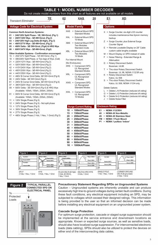
Precautionary Statement Regarding SPDs on Ungrounded SystemsCaution – Ungrounded systems are inherently unstable and can produce excessively high line-to-ground voltages during certain fault conditions. During these fault conditions, any electrical equipment including an SPD, may be subjected to voltages which exceed their designed ratings. This information is being provided to the user so that an informed decision can be made before installing any electrical equipment on an ungrounded power system.
Cascade Surge ProtectionFor optimum surge protection, cascade or staged surge suppression should be implemented at the service entrance and downstream locations as appropriate. Known or expected surge sources, as well as sensitive loads, should also have localized surge suppression. For interconnected electronic loads (data cabling), SPDs should also be utilized to protect the devices on either end of the interconnecting data cables.
Figure 2
A B C
GN
BREAKER
Phase C
Service
Phase B
Phase ASurge Counter
Advanced Protection Technologies
SilenceTest Count Reset
TYPICAL PARALLEL CONNECTED SPD ON ELECTRICAL PANEL
To Protected Loads
TABLE 1: MODEL NUMBER DECODERDo not create model numbers from this chart as all features are not available on all models
Transient Eliminator
Voltage Code for Electrical System Model Family Options
TE 02 XAS 20 E1 XD
X = Surge Counter, six-digit LCD counter includes maintenance-free Eprom memory backup
Z = Surge Counter, plus External Surge Counter Signal
E = Remote Locatable Display on 28” Cable custom cable lengths available
M = Mount Display on SPD instead of cableF = Noise Filtering - Extended Range &
Attenuation D = Rotary Disconnect Switch
Bussman, UL98T = Thru-door Rotary Disconnect Switch
Bussman, UL 98, NEMA 1/12/3R onlyK = Rotary Disconnect Switch
Katco, UL 508S = Thru-door Rotary Disconnect Switch
Katco, UL 508, NEMA 1/12/4 only
Delete OptionsL = Delete L-N Protection (reduces kA rating)G = Delete L-G Protection (reduces kA rating)N = Delete N-G Protection (reduces kA rating)J = Delete Noise Filter
Other Available Systems - Confirmation encouraged:15 = 254/127V Split Phase - 1Ø 3W+Grnd, (Fig 1)18 = 480/240V Split Phase, or Two legs of Wye, (Call) 21 = 220Y/127V Wye - 3Ø 4W+Grnd (Fig 2)41 = 520Y/300V Wye - 3Ø 4W+Grnd (Fig 2)42 = 415Y/240V Wye - 3Ø 4W+Grnd (Fig 2)43 = 400Y/230V Wye - 3Ø 4W+Grnd (Fig 2)44 = 440Y/250V Wye - 3Ø 4W+Grnd (Fig 2)51 = 480V B Corner Grnd Delta, 3Ø 3W+Grnd (Fig 6)06 = 240V Delta - 3Ø 3W+Grnd (Fig 4)61 = 240V B Corner Grnd Delta, 3Ø 3W+Grnd (Fig 6)07 = 380Y/220V Wye - 3Ø 4W+Grnd (Fig 2)09 = 600V Delta - 3Ø 3W+Grnd (Fig 4) & HRG Wye
(Available: 100kA, 150kA, 200kA, 250kA)91 = 600V B Corner Grnd Delta, 3Ø 3W+Grnd (Fig 6)
(Available: 100kA, 150kA, 200kA, 250kA)11 = 120V Single Phase (Fig 5)12 = 240V Single Phase (Fig 5) - Not split phase13 = 127V Single Phase (Fig 5)14 = 300V Single Phase (Fig 5)16 = 277V Single Phase (Fig 5)17 = 480V Single Phase (1 Hot, 1 Neu, 1 Grnd) (Fig 5)
10 = 100kA/Phase15 = 150kA/Phase20 = 200kA/Phase25 = 250kA/Phase30 = 300kA/Phase31 = 300kA/Phase40 = 400kA/Phase45 = 450kA/Phase50 = 500kA/Phase 60 = 600kA/Phase80 = 800kA/Phase90 = 900kA/Phase1K = 1000kA/Phase
XAS = External Mount SPD Standard Modes
XAL = External Mount SPD 10 Mode
XBS = External Mount SPD Two Modules Standard mode
XBL = External Mount SPDTwo Modules10 Mode
For Internal Mount (No Enclosures):XRS = Component SPD,
UL RecognizedStandard Modes
XRL = Component SPD, UL Recognized 10 Modes
XWS = Component SPD, UL RecognizedStandard Modes
XWL = Component SPD, UL Recognized 10 Modes
Common North American Systems:01 = 240/120V Split Phase - 1Ø, 3W+Grnd, (Fig 1)02 = 208Y/120V Wye - 3Ø 4W+Grnd, (Fig 2)03 = 240/120V High Leg Delta (B High), (Fig 3)04 = 480Y/277V Wye - 3Ø 4W+Grnd, (Fig 2)05 = 480V Delta - 3Ø 3W+Grnd, (Fig4) & HRG Wye08 = 600Y/347V Wye - 3Ø 4W+Grnd, (Fig2)
E1 = NEMA 1/12/3R/44X = NEMA 4X Non-Metallic 4S = NEMA 4X Stainless Steel FM = NEMA 1 Flush Mount P1 = NEMA 1 pullbox ‘indoor'
Enclosure Rating
Figure 1 Figure 2 Figure 3 Figure 4 Figure 5 Figure 6
SPLIT2 Hots, 1 Neu, 1 Grnd
HI-LEG DELTA (B High)3 Hots, (B HIGH), 1 Neu, 1 Grnd
SINGLE POLE1 Hot, 1 Neu, 1 Grnd
WYE3 Hots, 1 Neu, 1 Grnd
DELTA & HRG WYE3 Hots, 1 Grnd
CORNER GROUNDDELTA (B grounded)2 Hots, 1 Grnd
Hot (BLK)
Hot (BLK)
Neutral (WHT)V
V
}}
Ground (GRN)}
Phase A (BLK)Phase B (BLK)
Neutral (WHT)
Phase C (BLK)
Ground (GRN)
A
C
N
V
B
Phase A (BLK)Phase B (ORNG)
Neutral (WHT)
Phase C (BLK)
Ground (GRN)
}V V}Neutral (WHT)
Hot (BLK)
Ground (GRN)
Phase A (BLK)
Phase C (BLK)
Phase B (BLK)
Ground (GRN)
}V Phase A (BLK)
Phase C (BLK)
Ground (GRN)
V}
Surge Current Rating

4
Unpacking & Preliminary InspectionInspect the entire shipping container for damage or signs of mishandling. Remove the packing materials and further inspect the unit for any obvious shipping damages.
If any damage was found and is a result of shipping or handling, immediately file a claim with the shipping company and forward a copy to APT.
Storage EnvironmentThis SPD should be stored in a clean, dry environment. Storage temperature range is -40°C (-40°F) to +60°C (+140°F). Avoid exposure to high condensation.
PRE-INSTALLATION & INSTALLATION PLANNING
Operating EnvironmentThe standard unit uses a Type 1/12/3R/4 enclosure. Non-metallic polycarbonate 4X, stainless steel and Type 1 flush-mount or pull box enclosures are available as options. Before installing, ensure that your enclosure type and application are appropriate per NEMA 250 with regard to moisture, dirt, excessive dust, flammable materials or atmospheres, corrosive vapors, etc. Please consult factory if enclosure needs to be changed.
This SPD is designed in an ambient temperature range of -40°C (-40°F) to +60°C (+140°F) with a relative humidity of 0% to 95% (non-condensing). Excessive temperature may inadvertently operate internal thermal overtemperature protectors. On rare occasions in high temperature climates, SPDs inside clear cover polycabonate enclosures have experienced internal temperatures exceeding 200°F (94°C). We recommend positioning the unit so that the clear front avoids direct summer sunlight by shading or not facing west.
Line Side versus Load Side InstallationThe XA & XB family SPDs are tested and qualified as Type 1 SPDs per UL 1449 Fourth Edition and 2008 NEC®. This SPD can be installed on the Line Side of the service overcurrent device per 2008 NEC® Article 285. Type 1 SPDs may also be installed in Type 2 applications. As a generalization, it is more practical to install as Type 2 on load side of main overcurrent device for maintenance reasons. Such installations would be similar to traditional TVSS installations. (Note: cUL models are Type 2 due to different cUL criteria.)
XR and XW SPD modules are Type 4 components that have been evaluated by UL for use in Type 1 applications. (XR’s and XW’s are essentially XA’s without enclosures for installation within host electrical equipment.)
There may be circumstances where Line Side installation is desirable. Follow all applicable Code requirements for Line Side installation. We generally recommend that the SPD be installed with a disconnecting mechanism for servicing purposes.
Tip: APT offers an optional Disconnect Switch that has been UL evaluated as part of the SPD. This includes SCCR and Line Side suitability. If you do not use the APT Disconnect option, select a disconnect switch rated for line side (UL 98) having appropriate SCCR rating including any required overcurrent protection. This may be more time consuming
and expensive than anticipated. The optional Disconnect Switch is fully engineered and almost certainly easier, smaller and less expensive.
Audible NoiseSPD background noise is negligible or non-existent, and does not restrict the location of installation.
Mounting, Dimensions, and WeightThe XA & XB series include enclosures and are intended for wall mounting. The XR & XW series are component SPDs intended for installation within other electrical gear already having enclosures. See Table 2. Mechanical drawings are included in back of this manual (page 12).
TABLE 2: DIMENSIONS & WEIGHTSXA H/W/D (in. / mm.) Weight
Standard (and w/Opt. Disc. Switch & <300kA)
12" x 12" x 7" (305 x 305 x 177)
23 lbs (10.4 kg)
With Opt. Disc. Switch & >300kA
16" x 14" x 6.5" (406 x 356 x 165)
32 lbs(14.5 kg)
4X Non-Metallic (std.)(>300kA w/disc.)
14" x 12" x 7" (356 x 305 x 178)16" x 14" x 7" (406 x 356 x 178)
14 lbs (6.4 kg)21 lbs (9.5 kg)
4X Stainless(>300kA w/disc.)
12" x 12" x 7.5" (305 x 305 x 191)16" x 14" x 7.5" (406 x 356 x 191)
24 lbs (10.9 kg)33 lbs (15 kg)
Pullbox & Flush mount(>300kA w/disc.)
12" x 12" x 6" (305 x 305 x 152)16" x 14"x 6"
(406 x 356 x 152)
21 lbs (9.5 kg)29 lbs
(13.2 kg)
XB H/W/D (in. / mm.) WeightStandard
(includes Disc. Switch)20" x 20" x 7.5"(508 x 508 x 191)
52 lbs(23.6 kg)
4X Non-Metallic 24" x 24" x 8"(610 x 610 x 203)
52 lbs(23.6 kg)
4X Stainless 20" x 20" x 7.5"(508 x 508 x 191)
53 lbs(24 kg)
Pullbox & Flush mount 20" x 20" x 6"(508 x 508 x 152)
43 lbs(19.5 kg)
XR H/W/D (in. / mm.) WeightStandard 6.5" x 11" x 4.5"
(165 x 279 x 114)5 lbs
(2.3 kg)
With Opt. Disc. Switch on alum. backplane
10.75" x 10.88" 4.5"(273 x 276 x 114)
9 lbs(4.1 kg)
XW H/W/D (in. / mm.) WeightStandard 9" x 11" x 4.5"
(229 x 279 x 114)7 lbs
(3.2 kg)
With Opt. Disc. Switch on alum. backplane
14.75" x 12.9" x 5.25"(375 x 328 x 133)
11 lbs(5 kg)
Service ClearanceService clearance is needed at the front of the unit; 36 inches minimum is the required distance for clearance pursuant to the NEC®.
Lead Lengths & Maximizing SPD PerformanceSPDs must be located as close to the circuit as possible to minimize parasitic losses. Surges are high current, high frequency events that cause substantial voltage drops across conductors. This hurts SPD performance. Use the shortest & straightest possible leads. Pre-Plan installations and ensure that nearest breaker positions are used. If new construction, adjust breaker locations as appropriate.

5
Tip: Voltage drops for normal 120V or 277V lines might be 2-3V per hundred feet. In surge applications, voltage drops might be 100-150V per foot. These voltage drops add to clamping voltage, thus hurting performance. Make every effort to keep leads short and straight.
As distribution gear becomes larger, shorter leads are more difficult to accomplish. When longer leads are unavoidable, gently twist leads together (one to two twists per foot), or tie-wrap leads together.
Tip: surges create magnetic fields per the ‘right-hand rule’. When current goes in direction of thumb, magnetic field is in direction of curl of fingers. As surge current goes to SPD, fields are created in one direction. When the SPD sends those currents to neutral and/or ground, current goes in the opposite direction. If ‘coming & going’ are on the same axis, the magnetic fields can be cancelled, thus avoiding performance decrease. Gentle twists, bundling & tie-wraps accomplish this.
Shortest Leads Possible ▪ Leads must be as short and straight as possible -
See NEC® Art. 285.12 ▪ Pretend wire is $1000 per foot coming out of your pocket. ▪ No long leads ▪ No sharp bends ▪ No wire nuts ▪ How short is short enough? As short as you can make it. ▪ How long is too long? If anyone else can make it shorter.
Overcurrent ProtectionSPDs draw very little current under normal conditions and conduct for a brief duration upon encountering a transient surge current. This SPD contains internal overcurrent and overtemperature protection to protect against abnormal voltage conditions.
Supplemental overcurrent protection is not required to protect this SPD. However, connecting conductors require protection in Type 2 or 4 applications. Follow applicable codes.
Voltage RatingBefore installing SPD, verify that it has the same voltage rating as the power distribution system. Compare the SPDs nameplate voltage or model number and ensure that SPD configuration matches the intended power source. See Table 1.
The specifier or the user of the device should be familiar with the configuration and arrangement of the power distribution system in which any SPD is to be installed. The system configuration of any power distribution system is based strictly on how the secondary windings of the transformer supplying the service entrance main or load are configured. This includes whether or not the transformer windings are referenced to earth via a grounding conductor. The system configuration is not based on how any specific load or equipment is connected to a particular power distribution system.
480V System Example: SPDs should be installed per the electrical system, not per a load or motor’s wiring connection. For example, a 480V three phase motor might appear to be connected as a 480V Delta. In actuality, the serving distribution system might be a 480Y/277V grounded Wye, with or without a neutral pulled to the motor or MCC. The system is still a 480Y/277V Wye, even though the load is connected as a Delta. A grounded Wye has a defined reference to ground (i.e., neutral is bonded to ground). Some Delta systems are ungrounded, which have no reference to ground and are known to become unstable in certain situations. Such instability can cause line to ground voltage fluctuations that may prematurely fail SPDs. For this
reason, the NEC® Article 285 has placed SPD restrictions on ungrounded systems. As generalizations, SPDs for ungrounded systems can be installed on grounded systems with a clamping performance penalty. However, SPDs for grounded systems installed on ungrounded systems are almost certainly destined for premature failure. Call APT Tech Support at (800) 237-4567 for further information.
Circuit Breaker and Disconnect SwitchThe XA & XB family SPDs are tested and qualified as a Type 1 SPD per UL 1449 Fourth Edition and 2008 NEC®. This SPD can be installed on the line side of the service overcurrent device per 2008 NEC® Article 285. As a generalization, it is more practical to install on load side of main overcurrent device for maintenance reasons. When connected on load side of main disconnect, we suggest connecting via a 60A circuit breaker. The circuit breaker is the intended disconnect switch and provides short circuit protection to the connecting conductors. These SPDs have internal overload protection elements within the product. A breaker or disconnect is not required for the SPDs overcurrent protection. These SPDs have demonstrated 200kA Short Circuit Current Ratings (SCCRs). 120V & 120/240V models have demonstrated 100kA SCCRs. Refer to label on unit.
TerminalsTerminals will accept 14 - 2 AWG conductor and are provided for line (phase), neutral (if used), and equipment safety ground connections. 8 AWG is the minimum recommended wire size because UL testing and evaluation was performed using 8 AWG.
Wire Size and Installation TorqueThis is a parallel-connected SPD; it is not series-connected. The size of the SPD wiring is independent of the ampere rating of the protected circuit. Recommended wire is 6 AWG for phase, neutral and ground connections. Torque connections to 18 inch-pounds. Conductor length should be as short as possible.
If other wire sizes are used, we recommend that all conductors be the same gauge. Note that larger conductor might appear to be beneficial. However, large conductor tends to have the same inductance as smaller conductor, thus netting limited improvement in exchange for being more difficult to work with. Terminals accept 14 - 2 AWG conductor with 6 AWG being preferred. Coordinate conductor size and overcurrent protection per applicable codes.
If equipped, Disconnect Switch will accept 6 AWG to 1/0 AWG, with 6 AWG preferred. Torque connections to 18 inch-pounds. Do Not overtorque connections on Disconnect Switch as it Will Break the Disconnect Switch and will not be covered by warranty.
System GroundingAn equipment grounding conductor must be used on all electrical circuits connected to the SPD.
For the best performance, use a single point ground system where the service entrance grounding electrode system is connected to and bonded to all other available electrodes, building steel, metal water pipes, driven rods, etc. (for reference see: IEEE Std 142-2007).
For sensitive electronics and computer systems, we recommend that the ground impedance measurement be as low as possible. When metallic raceway is used as an additional grounding conductor, an insulated grounding

6
conductor should be run inside the raceway and sized per the NEC®. Adequate electrical continuity must be maintained at all raceway connections. Do not use isolating bushings to interrupt a metallic raceway run.
A separate isolated ground for the SPD is NOT recommended. Proper equipment connections to grounding system and ground grid continuity should be verified via inspections and testing on a regular basis as part of a comprehensive electrical maintenance program.
On 4-Wire Power Systems, neutral to ground bonding (Main Bonding Jumper) must be installed per the NEC®. Failure to do so WILL damage SPDs.
Internal Mounting of XR and XW Component SPDXR’s and XW’s are essentially XA’s without enclosures. XR’s and XW’s are intended for installation within host electrical equipment having suitable enclosures.
The experienced integrator will appreciate the simplicity of XR/XW. XR/XW’s are Type 4 SPDs and have been evaluated by UL for use as Type 1 (or Type 2) SPDs when installed in appropriate enclosures. All UL required safety testing is complete without needing additional safety apparatus. Contact factory for UL file Engineering Considerations. Mount SPD in appropriate enclosure, mount Diagnostic Display in appropriate location and follow appropriate instructions, including short leads. UL evaluation within your completed product should be easy and trouble free. Do not Hi-Pot test with SPD in circuit.
In many instances, a disconnecting means is appropriate for future service. A breaker serves this function, as well as provides overcurrent protection to the connecting conductors. If a breaker or optional Disconnect Switch are not used, consider a disconnect or safety switch having appropriate SCCR rating including any required overcurrent protection. Line side is likely to require a UL 98 switch where load side is likely to require a UL 508 (or UL 98) switch. This may be more time consuming, more expensive and physically larger than anticipated. APT offers an optional Disconnect Switch that has been UL evaluated as part of the SPD. The optional Disconnect Switch is fully engineered and almost certainly easier, smaller and less expensive. Please contact APT Technical Support as appropriate.
Mounting Diagnostic Display: Mount the Display in a user-friendly location, with consideration to weather and vandalism. Dimensions are in Figure 4 (page 7). A Display with a 28” connector cable is typically included. Longer
lengths are available. The Display is also mountable directly on the XR/XW module (shorter cables required). The standard Display includes mounting thru-holes and is not weather resistant. Contact factory for weather resistant NEMA 4 rated Display (with mounting studs instead of thru-holes and label material including UL 746C(f1) & UL 94-5VA flame rating).
UL 1283 required language concerning the installation of EMI Filtersa) An insulated grounding conductor that is identical in size and insulation material and thickness to the grounded and ungrounded circuit supply conductors, except that it is green with or without one or more yellow stripes, is to be installed as part of the circuit that supplies the filter. Reference should be made to Table 250-122 of the National Electrical Code regarding the appropriate size of the grounding conductor.
b) The grounding conductor mentioned in item a is to be grounded to earth at the service equipment or other acceptable building earth ground such as the building frame in the case of a high-rise steel-frame structure.
c) Any attachment-plug receptacles in the vicinity of the filter are to be of a grounding type, and the grounding conductors serving these receptacles are to be connected to earth ground at the service equipment or other acceptable building earth ground such as the building frame in the case of a high-rise steel-frame structure.
d) Pressure terminal or pressure splicing connectors and soldering lugs used in the installation of the filter shall be identified as being suitable for the material of the conductors. Conductors of dissimilar metals shall not be intermixed in a terminal or splicing connector where physical contact occurs between dissimilar conductors unless the device is identified for the purpose and conditions of use.
Optional Flush Mount Installation ConsiderationsThe XA & XB are approximately 6” deep. The unit will not mount flush unless there is at least 6” of depth clearance. The XA & XB are not designed to mount flush on a typical 2 x 4 stud wall.
Back Flange Mounting: Mount as close as possible to protected panel. Create a wall opening slightly larger than SPD. See Figure 4. Configure a robust backing plate inside the wall cavity 6 1/16” from the wall face such that the SPD is supported from its back. Note the mounting holes on the back flange. Also note that the SPD weighs 22-52 lbs. Be careful not to drop the SPD into the wall.
FLUSH MOUNT INSTALLATIONFigure 3
STEP 2: Mount SPD
STEP 3: Install Flush Mount Plate & Cover
Cutout slightly larger than SPD base
Mounting Plate 6 1/16” from outside of front wall
STEP 1: Prepare Wall - Must support 25-55lbs

7
Disconnect Switch (Opt. on XA, Std. on XB)The disconnect switch provides manual disconnection means for phase conductors and the neutral conductor. Ground is not switched.
Special care should be taken while pre-planning installation to ensure that leads are as short as possible. Most XA’s & XB’s in ‘square’ enclosures have backplanes that can be removed and repositioned to reduce leads. See Figure 8. (Models with rectangular enclosures may be repositioned by inverting only.) (Excludes thru-door handle options.)
There is limited working space around the Disconnect Switch. This is a consequence of reducing internal size and lead lengths. Please be patient. Disconnect switch will accept 6 AWG to 1/0 AWG, with 6 AWG preferred. Torque connections to 18 inch-pounds. OVER-TORQUING connections WILL BREAK the Disconnect Switch and will not be covered by warranty.
The disconnect switch is mounted on DIN-rail. It may be removed by gently pulling out the mounting tab at the bottom of the switch assembly.
APT is one of few SPD manufacturers that make Disconnect Switches available as a fully UL qualified option. The Disconnect Switch was included during UL certification and testing. The Short Circuit Current Rating posted on the UL label of the SPD includes the Disconnect Switch and supersedes any rating on the individual Disconnect Switch. When used in a Type 1 line-side application, the SPD including its Disconnect Switch has been UL tested and approved. Further evaluation is not required by UL, nor is a separate UL 98 rated switch required.
Figure 5
Diagnostic Cable Connector
ROTATING MODULE DESIGN ALLOWS FOR
SHORTER LEADSMounting Screws in Corners
Figure 4 INTERNAL MOUNT DISPLAY DIMENSIONS
0.00
0
0.000
1.384
1.699
2.014
2.329
3.437
0.951
4.61
8
0.55
9
0.25
0
4.87
5
0.250
3.690
�0.180 THRU 4 PL.
R0.375 4 PL.
Count Reset
3.96
3
1.79
8
2.86
1
CLEAR WINDOW TYP.
Phase C
Service
Phase B
Phase A
Test Silence
Surge Counter
0.497
0.65
4
1.32
4
1.99
4
Ø.50 BLACK BORDER TYP.
1.66
0
BLACK LETTERS (SURGE COUNTER)BACKGROUND TO BE PANTONE 441C
RED LETTERS (ALARM SILENCE ONLY) PANTONE 185C
BACKGROUND TO BE PANTONE 445C
PANTONE 441C 4 PLACES
R0.062 4 PL.
BLACK BORDER
2.99
9
2.077
2.7372.545
2.269
�0.125 TRANSLUCENT WINDOW 5 PL.
Module Rotation FeatureInstallation lead wire length must be minimized because longer leads hurt performance. Lead length may be reduced by rotating the module inside the enclosure. SPD ships with terminals pointing down. If installation lends itself toward other orientation, the module’s aluminum backplane can be unscrewed and reoriented. For example, if leads enter from top, rotate module assembly such that leads are shortest. Be careful with ribbon cable connector and take care to retighten screws & secure ribbon cable. Mounting screws are in four corners. Rectangular enclosures may be rotated up or down only. See Figure 5.
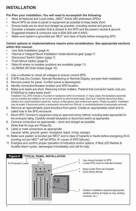
INSTALLATION
Pre-Plan your installation. You will need to accomplish the following: ▪ Meet all National and Local codes. (NEC® Article 285 addresses SPDs) ▪ Mount SPD as close to panel or equipment as possible to keep leads short. ▪ Ensure leads are as short and straight as possible, including neutral and ground.
Consider a breaker position that is closest to the SPD and the panel’s neutral & ground. ▪ Suggested breaker & conductor size is 60A-30A with 6 AWG. ▪ Make sure system is grounded per NEC® and clear of faults before energizing SPD.
Certain options or implementations require extra consideration. See appropriate sections within this manual: ▪ Line Side Installation (page 4) ▪ Internal or Integral Mount Installation inside electrical gear (page 7) ▪ Disconnect Switch Option (page 7) ▪ Flush Mount Option (page 6) ▪ Retro-fit where no breaker positions are available (page 11) ▪ UL/NEMA 3R Drain Holes (page 10)
1. Use a voltmeter to check all voltages to ensure correct SPD.2. If SPD has Dry Contact, Remote Monitoring or Remote Display, pre-plan their installation.3. Remove power for panel. Confirm panel is deenergized.4. Identify connection/breaker location and SPD location.5. Make sure leads are short. Reducing inches matters. Pretend that connector leads cost you
$1000/foot to make leads short! Installation Tips: SPD module is mounted on backplane within its enclosure. In many cases, the backplane assembly can be unbolted and rotated in two or four directions to yield shortest leads. See Fig 8. Carefully disconnect ribbon cable(s) and unbolt backplane assembly. Various configurations have limited work space. Please be patient. Installation may be easier if disconnect switch is temporarily removed from DIN-rail, or module/backplane is temporarily removed.
6. Remove an appropriately sized knockout from panel. Create an appropriately sized and lo-cated hole in the SPD enclosure.
7. Mount SPD. Connect to equipment using an approved wiring method, including seals appropriate for the enclosure rating. Carefully reinstall backplane or disconnect switch as appropriate.
8. Connect conductors as appropriate – short and straight as possible (Note that Hi-Legs are Phase B).
9. Label or mark conductors as appropriate (neutral: white, ground: green, energized: black, hi-leg: orange).
10. Make sure system is bonded per NEC® and is clear of hazards or faults before energizing (N-G bonding not per NEC® will fail SPDs: #1 cause of SPD failures).
11. Energize and confirm proper operation of indicators and/or options. If Red LED flashes & Audible Alarm cycles, deenergize immediately and call for help.
8
Figure 6
A B C
GN
BREAKER
Phase C
Service
Phase B
Phase ASurge Counter
Advanced Protection Technologies
SilenceTest Count Reset
TYPICAL PANEL INSTALLATION ▪ Use closest breaker to SPD ▪ Locate SPD close to intended breaker
▪ Keep Leads Short as Possible ▪ Avoid Sharp Bends
▪ Outdoor installation requires appropriate weather sealing at nipple (o-ring, sealing condulet, etc.)
To Protected Loads
9
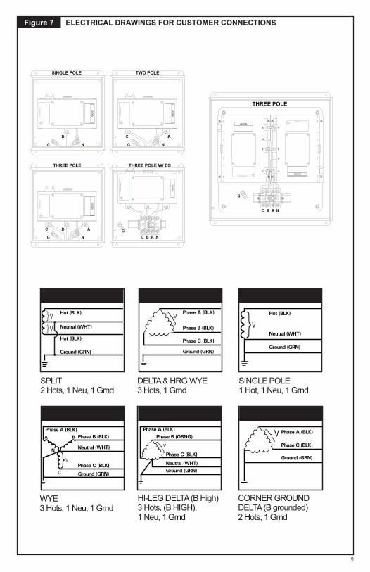
ELECTRICAL DRAWINGS FOR CUSTOMER CONNECTIONS
SPLIT2 Hots, 1 Neu, 1 Grnd
Hot (BLK)
Hot (BLK)
Neutral (WHT)V
V
}}
Ground (GRN)
WYE3 Hots, 1 Neu, 1 Grnd
}
Phase A (BLK)Phase B (BLK)
Neutral (WHT)
Phase C (BLK)
Ground (GRN)
A
C
N
V
B
HI-LEG DELTA (B High)3 Hots, (B HIGH), 1 Neu, 1 Grnd
Phase A (BLK)Phase B (ORNG)
Neutral (WHT)
Phase C (BLK)
Ground (GRN)
}V
DELTA & HRG WYE3 Hots, 1 Grnd
Phase A (BLK)
Phase C (BLK)
Phase B (BLK)
Ground (GRN)
}V
SINGLE POLE1 Hot, 1 Neu, 1 Grnd
V}Neutral (WHT)
Hot (BLK)
Ground (GRN)
CORNER GROUNDDELTA (B grounded)2 Hots, 1 Grnd
Phase A (BLK)
Phase C (BLK)
Ground (GRN)
V}
Figure 7
A
Advanced Protection Technologies, Inc.Clearwater, Florida
Listed
56E3
TVSS UR
L
CAUTION
2
1 3
4 6
5 7
8
Advanced Protection Technologies, Inc.Clearwater, Florida
Listed
56E3
TVSSURL
CAUTION
B
C
N
A
B
C
N
A B NC
G
THREE POLE
C
Advanced Protection Technologies, Inc.Clearw
ater, FloridaListed
56E3TVSS
UR
L
N
CAUTION
G
A
TWO POLE
2
1 3
4 6
5 7
8
Advanced Protection Technologies, Inc.Clearw
ater, FloridaListed
56E3U
RL
G
CAUTION
C B NA
THREE POLE W/ DS
Advanced Protection Technologies, Inc.Clearw
ater, FloridaListed
56E3U
RL
N
CAUTION
G
B
SINGLE POLE
C
Advanced Protection Technologies, Inc.Clearw
ater, FloridaListed
56E3U
RL
N
CAUTION
G
B A
THREE POLEC
Advanced Protection Technologies, Inc.Clearwater, Florida
Listed
56E3
TVSS UR
L
CAUTION
2
1 3
4 6
5 7
8
Advanced Protection Technologies, Inc.Clearwater, Florida
Listed
56E3
TVSSURL
CAUTION
B
A
N
C
B
A
N
AB NC
G
THREE POLE
C
Advanced Protection Technologies, Inc.Clearw
ater, FloridaListed
56E3TVSS
UR
L
N
CAUTION
G
A
TWO POLE
2
1 3
4 6
5 7
8
Advanced Protection Technologies, Inc.Clearw
ater, FloridaListed
56E3U
RL
G
CAUTION
C B NA
THREE POLE W/ DS
Advanced Protection Technologies, Inc.Clearw
ater, FloridaListed
56E3U
RL
N
CAUTION
G
B
SINGLE POLE
C
Advanced Protection Technologies, Inc.Clearw
ater, FloridaListed
56E3U
RL
N
CAUTION
G
B A
THREE POLE
10
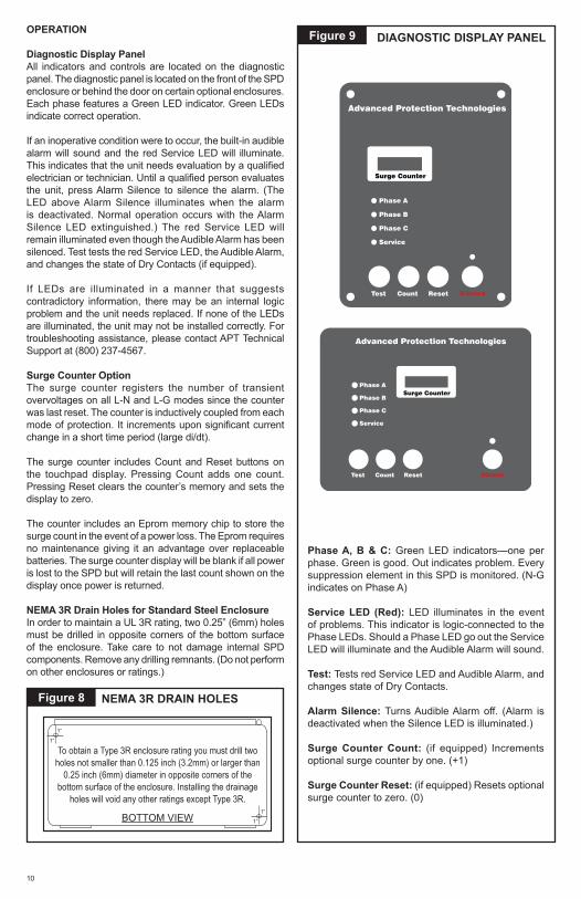
OPERATION
Diagnostic Display PanelAll indicators and controls are located on the diagnostic panel. The diagnostic panel is located on the front of the SPD enclosure or behind the door on certain optional enclosures. Each phase features a Green LED indicator. Green LEDs indicate correct operation.
If an inoperative condition were to occur, the built-in audible alarm will sound and the red Service LED will illuminate. This indicates that the unit needs evaluation by a qualified electrician or technician. Until a qualified person evaluates the unit, press Alarm Silence to silence the alarm. (The LED above Alarm Silence illuminates when the alarm is deactivated. Normal operation occurs with the Alarm Silence LED extinguished.) The red Service LED will remain illuminated even though the Audible Alarm has been silenced. Test tests the red Service LED, the Audible Alarm, and changes the state of Dry Contacts (if equipped).
If LEDs are illuminated in a manner that suggests contradictory information, there may be an internal logic problem and the unit needs replaced. If none of the LEDs are illuminated, the unit may not be installed correctly. For troubleshooting assistance, please contact APT Technical Support at (800) 237-4567.
Surge Counter OptionThe surge counter registers the number of transient overvoltages on all L-N and L-G modes since the counter was last reset. The counter is inductively coupled from each mode of protection. It increments upon significant current change in a short time period (large di/dt).
The surge counter includes Count and Reset buttons on the touchpad display. Pressing Count adds one count. Pressing Reset clears the counter’s memory and sets the display to zero.
The counter includes an Eprom memory chip to store the surge count in the event of a power loss. The Eprom requires no maintenance giving it an advantage over replaceable batteries. The surge counter display will be blank if all power is lost to the SPD but will retain the last count shown on the display once power is returned.
NEMA 3R Drain Holes for Standard Steel EnclosureIn order to maintain a UL 3R rating, two 0.25” (6mm) holes must be drilled in opposite corners of the bottom surface of the enclosure. Take care to not damage internal SPD components. Remove any drilling remnants. (Do not perform on other enclosures or ratings.)
Figure 8 NEMA 3R DRAIN HOLES
Figure 9
Phase A, B & C: Green LED indicators—one per phase. Green is good. Out indicates problem. Every suppression element in this SPD is monitored. (N-G indicates on Phase A)
Service LED (Red): LED illuminates in the event of problems. This indicator is logic-connected to the Phase LEDs. Should a Phase LED go out the Service LED will illuminate and the Audible Alarm will sound.
Test: Tests red Service LED and Audible Alarm, and changes state of Dry Contacts.
Alarm Silence: Turns Audible Alarm off. (Alarm is deactivated when the Silence LED is illuminated.)
Surge Counter Count: (if equipped) Increments optional surge counter by one. (+1)
Surge Counter Reset: (if equipped) Resets optional surge counter to zero. (0)
DIAGNOSTIC DISPLAY PANEL
Phase B
Phase C
Service
Phase A
Advanced Protection Technologies
Test Count Reset Silence
Surge Counter
Phase C
Service
Phase B
Phase ASurge Counter
Advanced Protection Technologies
SilenceTest Count Reset

11
appreciate SPD safety benefits on smoke detectors, medical equipment, security equipment, etc. Similarly, some AHJ’s appreciate the financial distress of failed microelectronic loads.
Dry Contact OptionTwo sets of Form C Dry Contacts are included with the Dry Contact option. Dry Contacts change state during inoperative conditions, including loss of power. Any status change can be monitored elsewhere via Dry Contacts.
A Terminal Block includes two sets of Normally Open (N.O.) and Normally Closed (N.C) contacts. Both sets of contacts operate the same. This is shown in Figure 10. A typical application using a Normally Closed configuration would connect to one set of the N.C. and Common terminals. During an inoperative condition, the SPDs dry contact would change state from normally closed to open. We generally suggest the Normally Closed configuration because it will detect a wiring defect, such as cut wire(s), where N.O. will not.
Please note: Dry Contacts are designed for low voltage or control signals only.
▪ Maximum switching current is 5A ▪ Maximum switching voltage is 240V DC or AC. ▪ Higher energy applications require additional relay
implementation outside the SPD.
An optional Remote Monitor accessory is available to provide visual and audible status. The Remote Monitor will consume one of the two sets of Dry Contacts.
Remote Monitor Accessory OptionA Remote Monitor is available for remote annunciation. It requires a standalone 120V power source (wall plug transformer) and uses one set of Form C dry contacts. The Remote Monitor can be configured to monitor several APT SPDs simultaneously. Installation is detailed in a separate document. Contact factory as appropriate.
Retro-fit Into Existing Panel with No Available Breaker PositionsThese can be difficult with limited options. Follow all applicable Codes:
• Consider consolidating loads in a manner that might free breaker positions.
• A ten foot tap rule in NEC® 240.21(B)(1) allows you to tap the bus as long as the tap conductors are rated at least 10% of the ampacity of the panel. This works well if the panel is about 600A or less: Tap the bus, run short 6 AWG leads to the SPD. An SPD with a Disconnect Switch allows for easier SPD servicing in the future. If the panel starts getting large (>800A), then the conductor size increases, which may also become too large to fit into the SPD lugs or too cumbersome to work with. In that case, consider tapping the bus per NEC® 240.21(B)(1). Run appropriate size conductors to a safety switch fused to 60A. Mount the SPD immediately adjacent to the safety switch. Connect SPD to the load side of the safety switch with 6 AWG. Keep all leads as short as possible.
• Install on Line Side by taking advantage of Type 1 SPD rating. Consider an SPD with a Disconnect Switch.
• In no-win situations, consider asking the Authority Having Jurisdiction (AHJ) for guidance. Some AHJ’s
NO
DRY CONTACTS
NCNC C NOC
DRY CONTACT OPTIONFigure 10

accelerated on Wye systems where SPDs are designed for grounded systems. (SPDs for ungrounded systems generally have higher MCOV to allow for L-G voltage fluctuations.) Failures of this nature are not defects in the SPDs workmanship or material. This is an installation error, not a warrantable situation.
A differential voltage circuit monitors neutral to ground voltage. When N-G voltage becomes excessive, a shrink-wrap covered resistor will heat. After several minutes, the shrink wrap will shrink around the resistor. This diagnostic tool will not detect instantaneously excessive N-G voltages. If shrunk or tampered with, the warranty is voided. (When the SPD is deenergized, this resistor can be accessed by qualified personnel under the display plate cover. See Figure 11.
Module Replacement & ServiceThe module(s) is field replaceable. Deenergize SPD, confirm with appropriate measurement equipment and discharge internal capacitance to ground. Mark locations and carefully disconnect diagnostic cables, dry contact connections, phase conductors, unplug parallel connections on XB models, etc. Depending on model, module may be bolted to backplane or the backplane may be part of the module assembly. Remove module/backplane. Reinstall in reverse order.
There are no user serviceable parts inside the module. We strongly recommend against disassembly.
Modules may be returned to the factory for factory service, qualification and return. Please contact the factory at (800) 237-4567 for assistance.
Display ReplacementThe display is field replaceable. Deenergize SPD, confirm with appropriate measurement equipment and discharge internal capacitance to ground. Mark locations and carefully disconnect diagnostic cables, contacts, connecting conductors, etc. Unbolt display and replace. Reinstall in reverse.
Note that a sealing gasket between the display and the enclosure is a key component ensuring weather resistance. Replace the gasket whenever the display is removed.
XB Series with two modulesThe XB features two redundant modules. One diagnostic display monitors both modules simultaneously via the parallel wire connections between the modules. These connectors plug in to each module, transferring information to internal logic on-board both modules.
12
MAINTENANCE
SPDs require minimal maintenance. We recommend periodic inspection of diagnostic indicators to ensure proper operation. We also recommend keeping the SPD clean as appropriate.
Troubleshooting & ServicePlease contact us for any service related issues. We want to take care of any problems.
Quality SPDs are designed and tested to withstand severe duty. However, there are various electrical anomalies that SPDs cannot protect against. These are generally Sustained Overvoltages also known as Temporary Overvoltages (TOVs). In this context, Sustained Overvoltages may be only a few cycles. Failed SPDs tend to be symptoms, not root causes. A failed SPD should be treated as a ‘canary in the coalmine’ suggesting further investigation as there may be a larger issue at play. Regardless of cause, SPDs attempt to protect their load until failure.
As noted above, the single largest ‘killer’ of SPDs is reference to ground issues. If the SPD shows problems on startup, there is reasonable chance of bonding/grounding/misapplication issue. This permanently damages the unit. If not corrected, it will happen again.
Tip: Visually confirm N-G bonding. Be aware that a voltmeter measuring N-G can be misleading. For example, N-G voltage could read 0V because neutral and ground are at the same potential by happenstance, not because they are bonded. Visually confirm bonding.
Tip: Experience indicates that regulation-challenged generators can cause Sustained Overvoltages, as well as ungrounded generators, and/or unusual load transfer systems.
Abnormal N-G Voltage IndicatorsThis SPD include N-G voltage indicators and a tattletale. If the SPD detects excessive N-G voltage, it will blink the Red Service LED and cycle the Audible Alarm while Phase LEDs are Green. If this occurs, DEENERGIZE THE SPD IMMEDIATELY and FIX THE N-G BONDING NOW. Otherwise, the SPD will fail.
Incorrectly bonded distribution systems are the number one killer of SPDs. If the XO or N-G bonding jumper is not installed, the electrical system has no reference to ground. It becomes an ungrounded system. Please see previous section regarding SPDs on ungrounded systems. Such systems are known to eventually produce abnormally high L-G voltages. SPDs will attempt to chase this system-level overvoltage abnormality until the SPD fails. This effect is
ABNORMAL N-G VOLTAGE INDICATORSFigure 11
13
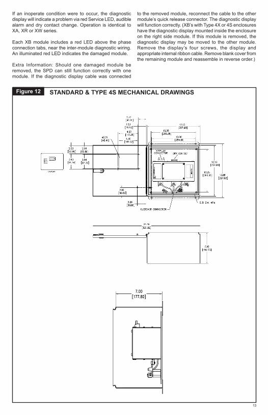
Figure 12 STANDARD & TYPE 4S MECHANICAL DRAWINGS
If an inoperate condition were to occur, the diagnostic display will indicate a problem via red Service LED, audible alarm and dry contact change. Operation is identical to XA, XR or XW series.
Each XB module includes a red LED above the phase connection tabs, near the inter-module diagnostic wiring. An illuminated red LED indicates the damaged module.
Extra Information: Should one damaged module be removed, the SPD can still function correctly with one module. If the diagnostic display cable was connected
to the removed module, reconnect the cable to the other module’s quick release connector. The diagnostic display will function correctly. (XB’s with Type 4X or 4S enclosures have the diagnostic display mounted inside the enclosure on the right side module. If this module is removed, the diagnostic display may be moved to the other module. Remove the display’s four screws, the display and appropriate internal ribbon cable. Remove blank cover from the remaining module and reassemble in reverse order.)
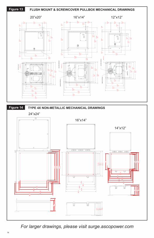
FLUSH MOUNT & SCREWCOVER PULLBOX MECHANICAL DRAWINGS
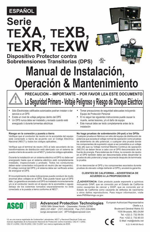
TYPE 4X NON-METALLIC MECHANICAL DRAWINGS
Figure 13
Figure 14
21.62 [549.25]
20.75 [527.05]
20.00 [508.00]
18.25 [463.55]
14.00 [355.60]
20.00 [508.00]
18.00 [457.20]
18.25 [463.55]
19.38 [492.14]
0.31 DIA. 4Plc
A B C N
A
G
Advanced Protection Technologies, Inc.Clearw
ater, FloridaListed
56E3
TVSSU
RL
CAUTION
2
13
46
57
8
DRY CO
NTAC
T
Adv
ance
d Pr
otec
tion
Tech
nolo
gies
, Inc
.Cl
earw
ater
, Flo
rida
List
ed
56E3
TVSS
U RL
CAUT
ION
B CN
A B CN
15.25 [387.35]
15.25 [387.35]
22.00 [558.80]
16.75 [425.45]
16.69 [423.88]
22.00 [558.80]
14.00 [355.60]
4.00 [101.60]
4.00 [101.60]
19.38 [492.13]
1.31 [33.34]
1.31 [33.34]
�0.25 [�6.35]
1.00 [25.40]
1.00 [25.40]
Ph
ase
C
Se
rvice
Ph
ase
B
Ph
ase
AS
urg
e C
ou
nte
r
CUSTOMER CONNECTION
DISPLAY CO
NN
ECTO
R
17.62 [447.65]
16.75 [425.45]
16.00 [406.40]
14.25 [361.95]
10.00 [254.00]
14.00 [355.60]
12.00 [304.80]
12.25 [311.15]
13.38 [339.74]
0.31 DIA. 4Plc
2
13
46
57
8
DISPLAY CONNECTORDRY CONTACT
Advanced Protection Technologies, Inc.Clearwater, Florida
Listed
56E3
TVSSURL
C B A N
G
OPTIONAL DISCONNECT
CUSTOMER CONNECTION
CAUTION
16.00 [406.40]
10.75 [273.05]
12.69 [322.28]
18.00 [457.20]
10.00 [254.00]
4.00 [101.60]
4.00 [101.60]
13.38 [339.73]
1.31 [33.34]
1.31 [33.34]
�0.25 [�6.35]
1.00 [25.40]
1.00 [25.40]
Ph
ase
C
Se
rvice
Ph
ase
B
Ph
ase
AS
urg
e C
ou
nte
r
13.62 [346.05]
12.75 [323.85]
12.00 [304.80]
10.25 [260.35]
6.00 [152.40]
12.00 [304.80]
10.00 [254.00]
10.25 [260.35]
11.38 [288.94]
0.31 DIA. 4Plc
2
13
46
57
8
C B A N
DISPLAY CONNECTORDRY CONTACT
Advanced Protection Technologies, Inc.Clearwater, Florida
Listed
56E3
TVSSURLG
OPTIONAL DISCONNECT
CUSTOMER CONNECTION
CAUTION
14.00 [355.60]
8.75 [222.25]
8.69 [220.68]
14.00 [355.60]
6.00 [152.40]
4.00 [101.60]
4.00 [101.60]
11.38 [288.93]
1.31 [33.34]
1.31 [33.34]
1.00 [25.40]
1.00 [25.40]
Ph
ase
C
Se
rvice
Ph
ase
B
Ph
ase
AS
urg
e C
ou
nte
r
20”x20” 16”x14” 12”x12”9.8810.2511.96
16.0113.96
12.25
12.58
14.58
11.03
16.95
5.966.30
7.136.37
0.30
14” x 12”
22.0121.0019.25
25.56
19.2521.00
8.947.61
27.06
24.11
24” x 24”
16” x 14”
12.1312.2513.97
17.59
15.96
14.70
14.25
13.28
16.70
16.65
6.787.12
7.95
7.307.48
24”x24”
16”x14”
14”x12”
For larger drawings, please visit surge.ascopower.com 14
V
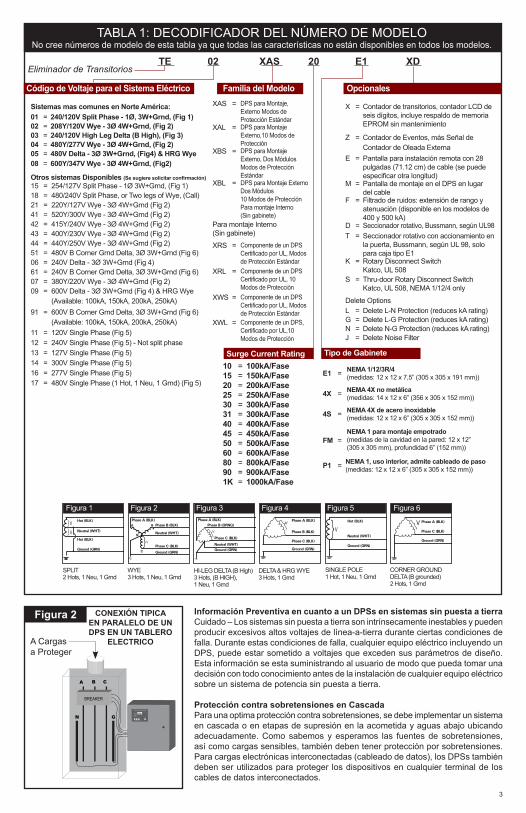
Manual de Instalación, Operación & Mantenimiento
ESPAÑOL
Riesgo en la conexión y puesta a tierraVerifique que el conductor de neutro en la acometida del equipo está conectado a tierra de acuerdo con el Código Eléctrico Nacional (NEC®) y todos los códigos aplicables..
Verifique que el terminal de neutro (XO) al lado secundario de los transformadores de distribución está aterrizado con el sistema de puesta a tierra de acuerdo con el NEC® y todos los códigos aplicables.
Durante la instalación en un sistema eléctrico el DPS no debe ser energizado hasta que el sistema eléctrico esté completamente instalado, inspeccionado y probado. Todos los conductores deben estar conectados incluyendo el neutro (de ser requerido). El voltaje nominal del DPS y el sistema debe ser verificado antes de energizar el DPS.
El incumplimiento de estas indicaciones puede conducir de modo anormal altos voltajes en el DPS. Esto puede hacer que el DPS falle. La garantía es anulada si el DPS es instalado incorrectamente y/o si el conductor neutro en el equipo de la acometida o aguas debajo de los sistemas tomados separadamente no está conectado a la puesta a tierra conforme al NEC®.
La Seguridad Primero - Voltaje Peligroso y Riesgo de Choque EléctricoPRECAUCION – IMPORTANTE – POR FAVOR LEA ESTE DOCUMENTO
▪ Sólo Electricistas calificados autorizados podrían instalar o dar servicio a un DPS
▪ Existe un nivel de voltaje peligroso dentro del DPS ▪ Un DPS nunca debe ser instalado y revisado cuando esté
energizado ó durante tormentas eléctricas
No haga pruebas de sobretensión (Hi-pot) a los DPSsCualquier prueba en fábrica o en sitio del equipo de distribución de potencia que exceda el voltaje normal de operación como pruebas de aislamiento de alto potencial, o cualquier otra prueba donde los componentes de supresión vayan a ser sometidos a un voltaje más alto que su Voltaje nominal Máximo Continuo de operación (MCOV) se deben llevar a cabo con el DPS desconectado de la fuente de energía. Para sistemas de 4 hilos, la conexión de neutro en el DPS también debe ser desconectada antes desarrollar la prueba de alto potencial y luego reconecte después de terminada la prueba.
El no desconectar el DPS y los componentes asociados durante pruebas de elevado voltaje dañarán el DPS y anulará la garantía.
Dispositivo Protector contra Sobretensiones Transitorias (DPS)
TEXA, TEXB,TEXR, TEXW
Serie
8.23.18 #8169 RevG
European Authorized RepresentativeObelis s.a.
Boulevard Général Wahis 531030 Brussels, BELGIUM
Tel: +(32) 2. 732.59.54Fax: +(32) 2. 732.60.03E-Mail: [email protected]
Advanced Protection Technologies 14550 58th Street North · Clearwater, Florida 33760(800) 237-4567 · (727) 535-6339 · Fax (727) 539-8955surge.ascopower.com · [email protected]
UL es una marca registrada de Underwriter Latoratories, NEC® y Nacional Electrical Code son marcas registradas de la Asociación Nacional de Protección contra Incendios, C62.41.1-2002, C62.41.2-2002, C62.45-2002, C62.72-2007 son marca registradas de IEEE.
▪ Tomar precauciones de seguridad adecuadas incluyendo Equipo de Protección Personal
▪ El no seguir las siguientes instrucciones puede causar la muerte, serias lesiones, y/o el daño de equipo
▪ Este manual debe ser leído completamente antes de la instalación
CLIENTES DE CALIFORNIA – ADVERTENCIA DE ACUERDO A LA PROPOSICION 65
ADVERTENCIA: Este producto puede exponerle a químicos incluyendo DINP, que es conocido por el Estado de California como causantes de cáncer y DIDP, que es conocido por el Estado de California como causante de defectos de nacimiento u otros daños reproductivos. Para mayor información, visite www.P65Warnings.ca.gov.

E1 = NEMA 1/12/3R/4(medidas: 12 x 12 x 7,5” (305 x 305 x 191 mm))
4X = NEMA 4X no metálica(medidas: 14 x 12 x 6” (356 x 305 x 152 mm))
4S = NEMA 4X de acero inoxidable(medidas: 12 x 12 x 6” (305 x 305 x 152 mm))
FM =NEMA 1 para montaje empotrado(medidas de la cavidad en la pared: 12 x 12” (305 x 305 mm), profundidad 6” (152 mm))
P1 = NEMA 1, uso interior, admite cableado de paso(medidas: 12 x 12 x 6” (305 x 305 x 152 mm))
INTRODUCCIÓN
Gracias por seleccionar un Dispositivo Protector contra Sobretensiones Transitorias (DPS) marca APT. Este es un equipo de alta calidad, suprime Sobretensiones de alta energía y fue diseñado para proteger equipos sensibles contra daños por Sobretensiones. Una adecuada instalación es importante para maximizar su desempeño. Por favor siga los pasos aquí señalados.
Todo este Manual de Operación y Mantenimiento debe ser leído antes de iniciar la instalación. Estas instrucciones no pretenden sustituir códigos nacionales o locales. Siga todos los códigos eléctricos aplicables para asegurar su cumplimiento. La instalación de este DPS sólo debe ser realizada por un electricista calificado.
Los DPSs APT son probados extensivamente conforme a las normas de la industria como ANSI/IEEE C62.41.1, C62.41.2, C62.45, C62.62, C62.72, UL 1449, UL 1283, IEC 61643, etc.
Este DPS es un dispositivo de puerto único conectado en paralelo para la entrada de servicio o acometida, tablero de distribución o aguas abajo de la instalación para la Categoría C, B o A de la IEEE.
Importantes cambios en la Nomenclatura de la Industria Efectivos 2008-2009Tener en cuenta que UL 1449 Cuarta Edición y NEC® 2008 Artículo 285 generó cambios sustanciales.
▪ El termino TVSS cambio a DPS ▪ Fueron creados los DPSs Tipo 1, 2, 3 y 4 ▪ la prueba UL 1449 de desempeño del voltaje remanente
cambió de 500A a 3,000A ▪ UL 1449 añadió una nueva prueba corriente nominal (In), que
consiste en pruebas de ciclo de operación más rigurosas
Este DPS cumple con la más recientes acciones regulatorias y son certificadas por UL como tal.
Para mayor información, por favor revise las más recientes ediciones de NEC® Art. 285, UL 1449.
INFORMACION GENERAL
Familia de Productos XA – Un Módulo en el GabineteXB – Dos Módulos en el GabineteXR – Un Módulo pequeño para la integración por OEMXW – Un Módulo Grande large para la integración por OEM
Cada uno está disponible con el sufijo ‘S’ o ‘L’, que designa modos Estándar (el más común) o específico de 10 modos (para aplicaciones específicas) respectivamente. Por ejemplo, XAS es un DPS en un gabinete con los modos de protección Estándar; XRL es un DPS sin gabinete para ir dentro del tablero de distribución principal que tiene diez modos protección específicos.
Las versiones XR y XW sin gabinete están disponibles para montaje interno dentro del tablero eléctrico. La versión XR está en 100-300kA. La versión XW está en 300-500kA.
Ambos están disponibles con la denominación L o S. El XA y familias XB son requeridos para el empleo como un Tipo 1 montaje externo DPS. XR y familias XW son el Tipo 4 DPSs intencionados para el Tipo 1 usos. Mirar el Decodificador de Número de modelo en la Mesa 1.
DPS Tipo 1Los DPSs Tipo 1 incluyen protección por sobrecorriente interna y han sido evaluados por UL para los más rigurosos requerimientos. Los DPSs Tipo 1 son apropiados para instalación en el lado de la línea de acometida o de la carga con respecto a la protección principal de sobre corriente. Los DPSs Tipo 1 pueden ser utilizados en aplicaciones Tipo 2.
Protección InternaEste dispositivo tiene al interior protección por sobrecorriente y por sobre temperaturas que desconectará los componentes de supresión dañados al final de su vida útil, pero mantendrá la carga energizada - ahora sin protección. Si esta situación es indeseable para la aplicación, siga estas instrucciones para reemplazar el dispositivo.
Instrucciones de MantenimientoEl mantenimiento de esta unidad consiste en el reemplazo del módulo(s) internos, desconecte el interruptor (si cuenta con un interruptor) y/o pantalla ensamblada en el equipo.
No hay partes útiles para el usuario dentro del módulo reemplazable. No intente desensamblar la unidad para economizar gastos.
Explicación Simplificada de OperaciónEl DPS censa un sobrevoltaje y crean un cortocircuito momentáneo para redireccionar la energía dañina del sobrevoltaje a la puesta a tierra. Ellos reinician automáticamente y esperan el siguiente sobrevoltaje. Esto es similar a la válvula de alivio de presión sobre un calentador de agua: la presión sube, la válvula abre para relevar la presión y luego reinicia. En un sistema eléctrico, el DPS detecta un sobrevoltaje, cortos temporales envían energía a la puesta a tierra y luego se reinician. Los DPSs son capaces de repetir esta función miles de veces.
Conexión en ParaleloEste es un DPS conectado en paralelo, no conectado en serie. Tal como indicamos arriba, un DPS drena el exceso de voltaje de un sistema eléctrico. Debido a la conexión en paralelo, es conveniente la instalación del DPS en cualquier lugar cerca al equipo a proteger. Este efecto es similar a vaciar el agua de algún inodoro en una casa; la presión en la ducha baja. En un sistema eléctrico, un DPS conectado en paralelo quitará el voltaje excesivo de todo el sistema (asumiendo una proximidad razonable).
TIP: Es críticamente importante que los cables de la instalación eléctrica sean configurados tan cortos y directos como sea posible. Evite conductores largos. Evite curvas cerradas. El recorrido de los conductores del DPS sea en el mismo ducto. El conductor no tiene que ser dimensionado para toda la carga - este DPS es conectado en paralelo, no conectado en serie. Generalmente, calibre No. 8 AWG funciona bien en este producto.
SPD Types: Types 1, 2, 3, & 4Based on Location within electrical distribution system
(also coincides with ANSI/IEEE C62.41.2 - 2002 Categories C, B & A)
Figura 1 NEC® Article 285 & UL 1449-4
2
3
Información Preventiva en cuanto a un DPSs en sistemas sin puesta a tierraCuidado – Los sistemas sin puesta a tierra son intrínsecamente inestables y pueden producir excesivos altos voltajes de línea-a-tierra durante ciertas condiciones de falla. Durante estas condiciones de falla, cualquier equipo eléctrico incluyendo un DPS, puede estar sometido a voltajes que exceden sus parámetros de diseño. Esta información se esta suministrando al usuario de modo que pueda tomar una decisión con todo conocimiento antes de la instalación de cualquier equipo eléctrico sobre un sistema de potencia sin puesta a tierra.
Protección contra sobretensiones en CascadaPara una optima protección contra sobretensiones, se debe implementar un sistema en cascada o en etapas de supresión en la acometida y aguas abajo ubicando adecuadamente. Como sabemos y esperamos las fuentes de sobretensiones, así como cargas sensibles, también deben tener protección por sobretensiones. Para cargas electrónicas interconectadas (cableado de datos), los DPSs también deben ser utilizados para proteger los dispositivos en cualquier terminal de los cables de datos interconectados.
Figura 2
A B C
GN
BREAKER
Phase C
Service
Phase B
Phase ASurge Counter
Advanced Protection Technologies
SilenceTest Count Reset
CONEXIÓN TIPICA EN PARALELO DE UN DPS EN UN TABLERO
ELECTRICOA Cargas a Proteger
TABLA 1: DECODIFICADOR DEL NÚMERO DE MODELO No cree números de modelo de esta tabla ya que todas las características no están disponibles en todos los modelos.
Eliminador de TransitoriosTE 02 XAS 20 E1 XD
X = Contador de transitorios, contador LCD de seis dígitos, incluye respaldo de memoria EPROM sin mantenimiento
Z = Contador de Eventos, más Señal de Contador de Oleada Externa
E = Pantalla para instalación remota con 28 pulgadas (71.12 cm) de cable (se puede especificar otra longitud)
M = Pantalla de montaje en el DPS en lugar del cable
F = Filtrado de ruidos: extensión de rango y atenuación (disponible en los modelos de 400 y 500 kA)
D = Seccionador rotativo, Bussmann, según UL98T = Seccionador rotativo con accionamiento en
la puerta, Bussmann, según UL 98, solo para caja tipo E1
K = Rotary Disconnect Switch Katco, UL 508
S = Thru-door Rotary Disconnect Switch Katco, UL 508, NEMA 1/12/4 only
Delete OptionsL = Delete L-N Protection (reduces kA rating)G = Delete L-G Protection (reduces kA rating)N = Delete N-G Protection (reduces kA rating)J = Delete Noise Filter
Otros sistemas Disponibles (Se sugiere solicitar confirmación)15 = 254/127V Split Phase - 1Ø 3W+Grnd, (Fig 1)18 = 480/240V Split Phase, or Two legs of Wye, (Call) 21 = 220Y/127V Wye - 3Ø 4W+Grnd (Fig 2)41 = 520Y/300V Wye - 3Ø 4W+Grnd (Fig 2)42 = 415Y/240V Wye - 3Ø 4W+Grnd (Fig 2)43 = 400Y/230V Wye - 3Ø 4W+Grnd (Fig 2)44 = 440Y/250V Wye - 3Ø 4W+Grnd (Fig 2)51 = 480V B Corner Grnd Delta, 3Ø 3W+Grnd (Fig 6)06 = 240V Delta - 3Ø 3W+Grnd (Fig 4)61 = 240V B Corner Grnd Delta, 3Ø 3W+Grnd (Fig 6)07 = 380Y/220V Wye - 3Ø 4W+Grnd (Fig 2)09 = 600V Delta - 3Ø 3W+Grnd (Fig 4) & HRG Wye
(Available: 100kA, 150kA, 200kA, 250kA)91 = 600V B Corner Grnd Delta, 3Ø 3W+Grnd (Fig 6)
(Available: 100kA, 150kA, 200kA, 250kA)11 = 120V Single Phase (Fig 5)12 = 240V Single Phase (Fig 5) - Not split phase13 = 127V Single Phase (Fig 5)14 = 300V Single Phase (Fig 5)16 = 277V Single Phase (Fig 5)17 = 480V Single Phase (1 Hot, 1 Neu, 1 Grnd) (Fig 5)
10 = 100kA/Fase15 = 150kA/Fase20 = 200kA/Fase25 = 250kA/Fase30 = 300kA/Fase31 = 300kA/Fase40 = 400kA/Fase45 = 450kA/Fase50 = 500kA/Fase 60 = 600kA/Fase80 = 800kA/Fase90 = 900kA/Fase1K = 1000kA/Fase
XAS = DPS para Montaje, Externo Modos de Protección Estándar
XAL = DPS para Montaje Externo,10 Modos de Protección
XBS = DPS para Montaje Externo, Dos MódulosModos de Protección Estándar
XBL = DPS para Montaje Externo Dos Módulos10 Modos de ProtecciónPara montaje Interno(Sin gabinete)
Para montaje Interno(Sin gabinete)
XRS = Componente de un DPSCertificado por UL, Modos de Protección Estándar
XRL = Componente de un DPSCertificado por UL, 10 Modos de Protección
XWS = Componente de un DPS Certificado por UL, Modos de Protección Estándar
XWL = Componente de un DPS,Certificado por UL,10 Modos de Protección
Sistemas mas comunes en Norte América:01 = 240/120V Split Phase - 1Ø, 3W+Grnd, (Fig 1)02 = 208Y/120V Wye - 3Ø 4W+Grnd, (Fig 2)03 = 240/120V High Leg Delta (B High), (Fig 3)04 = 480Y/277V Wye - 3Ø 4W+Grnd, (Fig 2)05 = 480V Delta - 3Ø 3W+Grnd, (Fig4) & HRG Wye08 = 600Y/347V Wye - 3Ø 4W+Grnd, (Fig2)
E1 = NEMA 1/12/3R/4(medidas: 12 x 12 x 7,5” (305 x 305 x 191 mm))
4X = NEMA 4X no metálica(medidas: 14 x 12 x 6” (356 x 305 x 152 mm))
4S = NEMA 4X de acero inoxidable(medidas: 12 x 12 x 6” (305 x 305 x 152 mm))
FM =NEMA 1 para montaje empotrado(medidas de la cavidad en la pared: 12 x 12” (305 x 305 mm), profundidad 6” (152 mm))
P1 = NEMA 1, uso interior, admite cableado de paso(medidas: 12 x 12 x 6” (305 x 305 x 152 mm))
Tipo de Gabinete
Figura 1 Figura 2 Figura 3 Figura 4 Figura 5 Figura 6
SPLIT2 Hots, 1 Neu, 1 Grnd
HI-LEG DELTA (B High)3 Hots, (B HIGH), 1 Neu, 1 Grnd
SINGLE POLE1 Hot, 1 Neu, 1 Grnd
WYE3 Hots, 1 Neu, 1 Grnd
DELTA & HRG WYE3 Hots, 1 Grnd
CORNER GROUNDDELTA (B grounded)2 Hots, 1 Grnd
Hot (BLK)
Hot (BLK)
Neutral (WHT)V
V
}}
Ground (GRN)}
Phase A (BLK)Phase B (BLK)
Neutral (WHT)
Phase C (BLK)
Ground (GRN)
A
C
N
V
B
Phase A (BLK)Phase B (ORNG)
Neutral (WHT)
Phase C (BLK)
Ground (GRN)
}V V}Neutral (WHT)
Hot (BLK)
Ground (GRN)
Phase A (BLK)
Phase C (BLK)
Phase B (BLK)
Ground (GRN)
}V Phase A (BLK)
Phase C (BLK)
Ground (GRN)
V}
Surge Current Rating
Código de Voltaje para el Sistema Eléctrico Familia del Modelo Opcionales
4
Desembalaje e Inspección PreliminarInspeccione completamente el empaque en cuanto a daño o señales de mal manejo. Quite los materiales de empaque y además inspeccione la unidad por cualquier daño evidente ocasionados durante el transporte.
Si encuentra algún daño ocasionado por el transporte o manejo, inmediatamente presentar una reclamación a la compañía transportadora y envíe una copia a APT.
Ambiente de almacenamientoEste DPS debe ser almacenado en un ambiente limpio y seco. El rango de temperatura de almacenamiento es -40°c (-40°f) a +60°C (+140°F). Evite la exposición a alta condensación.
PLANIFICACIÓN & PRE-INSTALACIÓN
Ambiente de OperaciónLa unidad estándar está en un gabinete Tipo 1/12/3R/4. El Tipo 4X no metálico en policarbonato, acero inoxidable y el Tipo 1 para montaje empotrado o caja de derivación están disponibles como opciones. Antes de la instalación, asegure que el tipo de gabinete y la aplicación son las adecuadas respecto a NEMA 250 en relación a la humedad, la suciedad, el polvo excesivo, materiales inflamables o atmósferas, vapores corrosivos, etc. Si necesito un cambio en el gabinete por favor consulte en fábrica.
Este DPS es diseñado para un rango de temperatura ambiente de-40°c (-40°F) to +60°C (+140°F) con una humedad relativa del 0% al 95% (sin condensación). La temperatura excesiva puede accidentalmente operar las protecciones térmicas de sobre temperatura.
En raras ocasiones en climas con altas temperaturas, los DPSs con tapa clara de policabonato dentro del gabinete han experimentado temperaturas internas que exceden 200°F (94°C). Recomendamos colocar la unidad de modo que evite durante el verano que la luz del sol llegue directa sobre la tapa frontal clara, para protegiendo del sol o no instalarlo de cara al oeste.
Instalación del Lado de Línea versus del Lado de CargaLa familia XA y XB DPSs son probados y calificados como DPSs Tipo 1 por UL 1449 Cuarta Edición y NEC® 2008. Este DPS puede ser instalado sobre el Lado de la Acometida del dispositivo de sobrecorriente de servicio por 2008 NEC® Art. 285. Los DPSs Tipo 1 también pueden ser instalados en aplicaciones del Tipo 2. Generalmente, es más práctico para instalar como Tipo 2 al lado de carga respecto al dispositivo principal de sobrecorriente por motivos de mantenimiento. Tales instalaciones serían similares a las instalaciones tradicionales de TVSSs. (Nota: cUL modelos son el Tipo 2 debido a criterios diferentes cUL.)
Los módulos del DPS, XR y XW son componentes Tipo 4 que han sido evaluados por UL para uso en aplicaciones Tipo 1. (Los XR’s y los XW’s son esencialmente XA’s sin gabinete para instalación dentro de la celda para equipo eléctrico).
Puede haber circunstancias donde la instalación del Lado de la Acometida es preferible. Siga todas las exigencias de los Código aplicables para la instalación en el Lado de la Acometida. Generalmente recomendamos que el DPS sea instalado con un mecanismo de desconexión por razones de mantenimiento.
TIP: APT ofrece un Interruptor de Desconexión opcional que ha sido certificado por UL como una parte del DPS. Esto incluye un SCCR y un conmutador del lado de la Acometida. Si usted no necesita el uso de esta opción de desconexión por parte de APT, seleccione un interruptor para desconexión calculado para el lado de la acometida (UL 98) teniendo un valor de SCCR adecuado que incluya cualquier requerimiento de protección por sobrecorriente.
Esto puede tomar más tiempo y ser más costoso que lo esperado. El Interruptor de Desconexión opcional está
completamente hecho a la medida y casi seguramente más fácil, más pequeño y menos costoso. Por favor póngase en contacto con el Soporte técnico de APT en caso de requerirlo.
Ruido AudibleEl ruido de fondo del DPS es insignificante o inexistente, y no limita la ubicación de instalación.
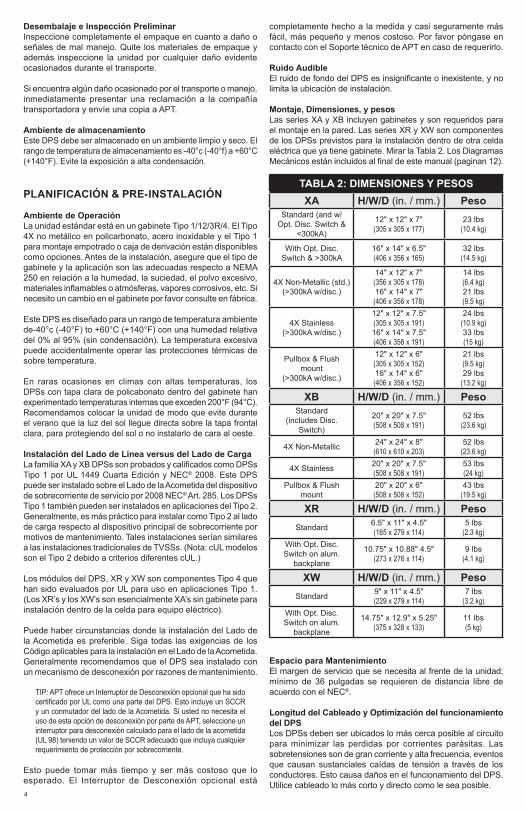
Montaje, Dimensiones, y pesosLas series XA y XB incluyen gabinetes y son requeridos para el montaje en la pared. Las series XR y XW son componentes de los DPSs previstos para la instalación dentro de otra celda eléctrica que ya tiene gabinete. Mirar la Tabla 2. Los Diagramas Mecánicos están incluidos al final de este manual (paginan 12).
TABLA 2: DIMENSIONES Y PESOSXA H/W/D (in. / mm.) Peso
Standard (and w/Opt. Disc. Switch &
<300kA)
12" x 12" x 7" (305 x 305 x 177)
23 lbs (10.4 kg)
With Opt. Disc. Switch & >300kA
16" x 14" x 6.5" (406 x 356 x 165)
32 lbs(14.5 kg)
4X Non-Metallic (std.)(>300kA w/disc.)
14" x 12" x 7" (356 x 305 x 178)16" x 14" x 7" (406 x 356 x 178)
14 lbs (6.4 kg)21 lbs (9.5 kg)
4X Stainless(>300kA w/disc.)
12" x 12" x 7.5" (305 x 305 x 191)16" x 14" x 7.5" (406 x 356 x 191)
24 lbs (10.9 kg)33 lbs (15 kg)
Pullbox & Flush mount
(>300kA w/disc.)
12" x 12" x 6" (305 x 305 x 152)16" x 14" x 6" (406 x 356 x 152)
21 lbs(9.5 kg)29 lbs
(13.2 kg)
XB H/W/D (in. / mm.) PesoStandard
(includes Disc. Switch)
20" x 20" x 7.5"(508 x 508 x 191)
52 lbs(23.6 kg)
4X Non-Metallic 24" x 24" x 8"(610 x 610 x 203)
52 lbs(23.6 kg)
4X Stainless 20" x 20" x 7.5"(508 x 508 x 191)
53 lbs(24 kg)
Pullbox & Flush mount
20" x 20" x 6"(508 x 508 x 152)
43 lbs(19.5 kg)
XR H/W/D (in. / mm.) PesoStandard 6.5" x 11" x 4.5"
(165 x 279 x 114)5 lbs
(2.3 kg)With Opt. Disc. Switch on alum.
backplane
10.75" x 10.88" 4.5"(273 x 276 x 114)
9 lbs(4.1 kg)
XW H/W/D (in. / mm.) PesoStandard 9" x 11" x 4.5"
(229 x 279 x 114)7 lbs
(3.2 kg)With Opt. Disc. Switch on alum.
backplane
14.75" x 12.9" x 5.25"(375 x 328 x 133)
11 lbs(5 kg)
Espacio para MantenimientoEl margen de servicio que se necesita al frente de la unidad; mínimo de 36 pulgadas se requieren de distancia libre de acuerdo con el NEC®.
Longitud del Cableado y Optimización del funcionamiento del DPSLos DPSs deben ser ubicados lo más cerca posible al circuito para minimizar las perdidas por corrientes parásitas. Las sobretensiones son de gran corriente y alta frecuencia, eventos que causan sustanciales caídas de tensión a través de los conductores. Esto causa daños en el funcionamiento del DPS. Utilice cableado lo más corto y directo como le sea posible.

5
Planifique las instalaciones y asegure que está utilizando el interruptor más cercano. Si es una construcción nueva, ajuste la posición del interruptor según corresponda.
TIP: Las caídas de voltaje para líneas normales de 120V o 277V podrían ser 2-3V por cada cien pies (30 mts). En aplicaciones de sobretensiones, las caídas de voltaje podrían ser 100-150V por pie (30 cms). Estas caídas de voltaje se añaden al voltaje remanente o (clampling de voltaje), afectando de esta manera su funcionamiento. Trate al máximo de mantener los conductores cortos y directos.
En tanto que el centro de distribución sea más grande, es más difícil lograr cables más cortos. Cuando es inevitable un cableado más largo, entorche con cuidado los conductores juntándolos (una a dos vueltas por pie (30 cms)), o utilice amarras (bridas) plásticas para juntar los cables.
TIP: las sobretensiones crean campos magnéticos según “la regla de la mano derecha”. Cuando la corriente entra en la dirección de pulgar, el campo magnético está en la dirección que cierran los dedos. De la manera como la corriente de la sobretensión va al DPS, los campos son creados en una dirección. Cuando el DPS envía aquellas corrientes a neutro y/o la tierra, la corriente entra en dirección de frente. “Viniendo y yendo” están sobre el mismo eje, los campos magnéticos pueden ser cancelados, evitando así la disminución de desempeño. Esto se logra haciendo un entorchado suave y atando con amarras (bridas).
Cables tan cortos como sea posible ▪ Los cables deben ser tan cortos y directos como sea posible –
Vea NEC® Art 285.12 ▪ Suponga que el cable cuesta $1000 dólares por pie, si y utiliza
más del necesario estará perdiendo dinero. ▪ No utilice cables largos ▪ No haga curvas cerradas ▪ No utilice conectores de entrada a rosca ▪ ¿Qué tan corto es bastante corto? Tan corto como usted pueda hacerlo. ▪ ¿Qué tan largo es demasiado largo? Si aun puede hacerlo más corto.
Protección por sobrecorrienteLos DPSs toman muy poca corriente en condiciones normales y conducen por un breve momento al encontrase una corriente de un sobrevoltaje transitorio. Este DPS incluye la protección interna por sobrecorriente y sobre temperatura para proteger contra condiciones de voltaje anormales. No se requieren protección por sobrecorriente adicional para proteger este DPS. Sin embargo, se requiere la protección para la conexión de los conductores en aplicaciones Tipo 2 o 4. Siga las normas aplicables.
Voltaje NominalAntes de la instalación DPS, verifique que éste tiene el mismo voltaje nominal que el sistema de distribución de potencia. Compare el voltaje en la etiqueta del DPS o el número de modelo y asegure que la configuración del DPS concuerda con la de la fuente de potencia prevista. Vea la Tabla 2.
La persona que especifica o el usuario del dispositivo deben estar familiarizados con la configuración y el arreglo del sistema de distribución de potencia en el cual cualquier DPS ha de ser instalado. La configuración de cualquier sistema de distribución de potencia está basada estrictamente en como los devanados secundarios del transformador que suministra la acometida principal o la carga son configurados. Esto incluye si realmente los devanados del transformador son referidos a tierra a través de un conductor de puesta a tierra. La configuración del sistema no está basada en como cualquier carga específica o equipo son unidos a un sistema de distribución de potencia en particular.
Ejemplo un Sistema de 480V: Los DPSs deben ser instalados de acuerdo con el sistema eléctrico, no por una carga o el alambrado la conexión del motor. Por ejemplo, suponga que un motor trifásico de 480V parece estar conectado en Delta de 480V. En la práctica, el sistema de distribución que lo alimenta podría ser un 480Y/277V en Y conectada a tierra, con o sin un neutro tomado del motor o CCM. El sistema es todavía una
Y 480Y/277V, aun cuando la carga está conectada en Delta. Un sistema Y aterrizado tiene una referencia definida a tierra (p. Ej. el neutro está conectado a tierra). Algunos sistemas en Delta están sin conexión a tierra, los cuales no tiene ninguna referencia a tierra y sabemos que van a causar inestabilidad en ciertas situaciones. Tal inestabilidad puede causar fluctuaciones en el voltaje línea a tierra que pueden ocasionar la falla prematura de los DPSs. Por esta razón, el NEC® Artículo 285 ha establecido restricciones para los DPSs en sistemas sin puesta a tierra. Generalmente, los DPSs para sistemas sin puesta a tierra pueden ser instalados en sistemas conectados a tierra con un detrimento en el desempeño del voltaje remanente. Sin embargo, los DPSs para sistemas con conexión a tierra instalados en sistemas sin puesta a tierra casi seguramente están destinados a la falla prematura. Llame a Soporte técnico de APT en Estados Unidos al (727) 535-6339 o al Distribuidor Autorizado de su País.
Interruptor (Circuit Breaker) e Interruptor de DesconexiónTLa familia de DPSs XA y XB son probados y certificados como un DPSs Tipo 1 por UL 1449 Cuarta Edición y NEC® 2008. Este DPS puede ser instalado sobre el lado de la línea del dispositivo de sobrecorriente de la acometida de acuerdo con NEC® 2008 Artículo 285. Por lo general, es más práctico instalar al lado de la carga respecto al dispositivo principal de sobrecorriente por motivos de mantenimiento.
Cuando conectamos al lado de la carga desde el interruptor principal, recomendamos conectarlos a través de un interruptor (breaker) de 50-30 A. El interruptor sirve como un conmutador de desconexión y proporciona la protección de cortocircuito a los cables que se están conectando. La Serie XD tiene elementos internos de protección de sobrecarga dentro del producto. Un interruptor o breaker no se requiere para la protección por sobrecorriente del DPS. Los DPSs XD han sido probados para 200kA de Corriente Nominal de Cortocircuito (SCCR). El XD’S 120V y 120/240V se han probado para un nivel de 100kA SCCRs. Consulte la etiqueta en la unidad.
TerminalesSe permite el uso de terminales 14 - 2 AWG para conductores y son suministrados para la línea (la fase), neutro (si es usado), y conexiones de tierra de equipo de seguridad. 8 AWG es el tamaño mínimo recomendado de cable porque las pruebas de UL y la evaluación fueron realizadas utilizando 8 AWG.
Tamaño De cable y Torque de InstalaciónEste es un DPS conectado en paralelo; no está conectado en serie. El calibre del cableado del DPS es independiente de capacidad en amperios del circuito protegido. El cable recomendado es 6 AWG para la fase, neutro y las conexiones de tierra. El torque de conexión hasta 18 libras por pulgada. La longitud del conductor deber ser tan corta como sea posible. Si usa otros tamaños de cable, recomendamos que todos los conductores sean del mismo calibre. Note que un conductor más grande podría parecer ser favorable; sin embargo, este tiende a tener la misma inductancia que un conductor más pequeño y este es más difícil de manipular.
Se requieren terminales para conductores 14 - 2 AWG siendo preferible 6 AWG. Coordine el tamaño del conductor y la protección por sobrecorriente de acuerdo con los códigos aplicables.
De existir, el Interruptor de desconexión permitirá 6 AWG a 1/0 AWG, con 6 AWG preferiblemente. El torque de conexión a 18 libras de pulgada. No haga un torque mayor a las conexiones en el Interruptor Desconexión esto Romperá el Interruptor Desconexión y no será cubierto por la garantía.
Sistema de Puesta a TierraUn conductor de puesta a tierra del equipo debe ser usado en todo el circuito eléctrico conectado al DPS.
Para un mejor funcionamiento, use un solo punto del sistema de tierra donde el electrodo de tierra de la acometida es conectado
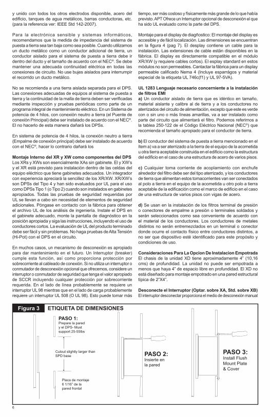
y unido con todos los otros electrodos disponible, acero del edificio, tanques de agua metálicos, barras conductoras, etc. (para la referencia ver: IEEE Std 142-2007).
Para la electrónica sensible y sistemas informáticos, recomendamos que la medida de impedancia del sistema de puesta a tierra sea tan baja como sea posible. Cuando utilizamos un ducto metálico como un conductor adicional de tierra, un conductor aislado para el sistema de puesta a tierra debe ir dentro del ducto y el tamaño de acuerdo con el NEC®. Se debe mantener una adecuada continuidad eléctrica en todas las conexiones de circuito. No use bujes aislados para interrumpir el recorrido un ducto metálico.
No se recomienda a una tierra aislada separada para el DPS. Las conexiones adecuadas de equipos al sistema de puesta a tierra y la continuidad de la malla de tierra deben ser verificadas mediante inspección y pruebas periódicas como parte de un programa integral de mantenimiento eléctrico. En un Sistema de potencia de 4 hilos, con conexión neutro a tierra (el Puente de conexión Principal) debe ser instalado de acuerdo con el NEC®. El no hacerlo de esta manera dañará los DPSs.
En sistema de potencia de 4 hilos, la conexión neutro a tierra (Empalme de conexión principal) debe ser instalado de acuerdo con el NEC®, hacer lo contrario dañará los
Montaje Interno del XR y XW como componentes del DPSLos XRs y XWs son esencialmente XAs sin gabinete. El y XW’s y el XR está previsto para instalación dentro de las celdas del equipo eléctrico que tiene gabinetes adecuados. Un integrador con experiencia apreciará la sencillez de los XR/XW. XR/XW’s son DPSs del Tipo 4 y han sido evaluados por UL para el uso como DPSs Tipo 1 (o Tipo 2) cuando son instalados en gabinetes apropiados. Todas las pruebas de seguridad requeridas por UL se llevan a cabo sin necesidad de elementos de seguridad adicionales. Póngase en contacto con la fábrica para obtener el archivo UL de los análisis de ingeniería. Instale el DPS en el gabinete adecuado, monte la pantalla de diagnóstico en la posición apropiada y siga las instrucciones, incluyendo el uso de conductores cortos. La evaluación de UL del producto terminado debe ser fácil y sin problemas. No haga pruebas de Alta Tensión (Hi-Pot) con el DPS en el circuito.
En muchos casos, un mecanismo de desconexión es apropiado para dar mantenimiento en el futuro. Un Interruptor (breaker) cumple esta función, así como proporciona protección por sobrecorriente al cableado de conexión. Si no utiliza un interruptor o conmutador de desconexión opcional que ofrecemos, considere un interruptor o conmutador de seguridad que tenga el valor apropiado de SCCR incluyendo cualquier protección por sobrecorriente requerida. En el lado de línea probablemente se requiere un interruptor UL 98 mientras que en el lado de carga probablemente requiere un interruptor UL 508 (O UL 98). Esto puede tomar más
6
tiempo, ser más costoso y físicamente más grande de lo que había previsto. APT Ofrece un Interruptor opcional de desconexión el que ha sido UL evaluado como la parte del DPS.
Montaje para el display de diagñostico: El montaje del display es accesible y de fácil localización. Las dimensiones se encuentran en la figura 4 (pag 7). El desplay contiene un cable para la instalación. Las extensiones de cable están disponibles en la fábrica. El display es directamente compatible en el módulo XR/XW (y requiere cables cortos). El esplay standard en estos módulos no son permeables. Cantactar la fábrica para un display permeable calificado Nema 4 (Incluye esparrágos y material especial de la etiqueta UL 746c(f1) y UL 97-5VA).
UL 1283 Lenguaje necesario concerniente a la instalación de filtros EMIa) Un conductor aislado de tierra que es idéntico en tamaño, material aislante y calibre al de tierra y a los conductores no aterrizados del circuito de alimentación, excepto que este es verde con o sin uno o más líneas amarillas, va a ser instalado como parte del circuito que alimentará el filtro. Podemos referirnos a la tablea 250-122 de el Código Eléctrico Nacional (NEC®) que recomienda el tamaño apropiado para el conductor de tierra.
b) El conductor del sistema de puesta a tierra mencionado en el ítem a) va a ser aterrizado a la tierra de el equipo de la acometida u otra tierra aceptable construida en el edificio como la estructura del edificio en el caso de una estructura de acero de varios pisos. c) Cualquier toma corriente de acoplamiento con enchufe alrededor del filtro debe ser del tipo aterrizado, y los conductores de tierra que alimentan estos tomacorrientes van ser conectados al polo a tierra en el equipo de la acometida u otro polo a tierra aceptable de la edificación como el marco de edificio en el caso de una estructura de varios pisos con vigas de acero.
d) Se usan en la instalación de los filtros terminal de presión o conectores de empalme a presión o terminales soldados y serán seleccionados como sea conveniente de acuerdo con el material de los conductores. Los conductores de metales distintos no serán entremezclados en un terminal o conector donde ocurre el contacto físico entre conductores distintos, a no ser que dispositivo esté identificado para este propósito y condiciones de uso.
Consideraciones Para La Opcion De Instalacion EmpotradaEl chasis de la unidad XD tiene aproximadamente 4” (10,16 cms) de profundidad. La unidad no puede ser empotrada a menos que haya 4” de espacio libre en profundidad. El XD no está diseñado para montaje empotrado en una pared estructural típica de 2”X4”.
Desconecte el Interruptor (Optar. sobre XA, Std. sobre XB)El interruptor desconectar proporciona el medio de desconexión manual
ETIQUETA DE DIMENSIONESFigura 3
PASO 2: Insierte en la pared
PASO 3: Install Flush Mount Plate & Cover
Cutout slightly larger than SPD base
Placa de montaje 6 1/16” de la pared frontal
PASO 1: Prepare la pared y el DPS- Must support 25-55lbs

para revisores de fase y el revisor neutro. La tierra no es cambiada.
El cuidado especial debería ser tomado preplanificando la instalación para asegurar que conduce son tan corto como posible. El y XB’S de la Mayor parte de XA en recintos ‘cuadrados’ tiene las placas madre que pueden ser quitadas y colocadas de nuevo para reducir conduce. Mirar la Figura 8. (Los modelos con recintos rectangulares pueden ser colocados de nuevo por invirtiendo sólo.) (Excluye opciones a través de picaporte.)
Allí es limitado trabajando el espacio alrededor del Interruptor Desconectar. Esto es una consecuencia de reducir el tamaño interno y longitudes de plomo. Por favor esté paciente.
Desconecte el interruptor aceptará 6 AWG a 1/0 AWG, con 6 AWG preferidos. Conexiones de momento de rotación a 18 libras de pulgada. OVERTORQUING conexiones ROMPERÁ el Interruptor Desconectar y no será cubierto según la garantía.
El interruptor desconectar es montado sobre el RIEL DIN. Puede ser quitado por con cuidado sacando la etiqueta creciente en el fondo de la asamblea de interruptor. DPS es uno de pocos fabricantes DPS que hacen Desconectan Interruptores disponible como un totalmente UL la opción calificada. El Interruptor Desconectar fue incluido durante la certificación UL y pruebas. La corriente de Cortocircuito la Posición de al corriente sobre la etiqueta de UL DEL DPS incluye el Interruptor Desconectar y reemplaza cualquier posición sobre el individuo Desconectan el Interruptor. Cuando usado en un Tipo 1 uso de lado de línea, el DPS incluyendo su Para desconectar el Interruptor ha sido UL probado y se ha aprobado. UL no requiere la remota evaluación, tampoco UL separado 98 es tasado el interruptor requerido.
Rasgo de Rotación de MóduloLa longitud de cable de plomo de instalación debe ser reducida al mínimo porque más largo conduce a hacer daño el funcionamiento. Pueden reducir la longitud de plomo haciendo girar el módulo dentro del recinto. DPS embarca con terminales que señalan abajo. Si la instalación se presta hacia otra orientación, la placa madre de aluminio del módulo puede ser desatornillada y reorientada.
Por ejemplo, si conduce a entrar de la cima, hacer girar la asamblea de módulo tal que conduce son lo más corto. Tenga cuidado con el conector de cable de cinta y tenga cuidado para
apretar de nuevo tornillos y el cable de cinta seguro. Tornillos crecientes están en cuatro esquinas. Recintos rectangulares pueden ser hechos girar encima de o abajo sólo. Mirar la Figura 5.
Opción Complementaria de Monitoreo RemotoUn Monitor Remoto está disponible para la supervisión remota. Esto requiere una fuente de alimentación de 120V independiente (un transformador de enchufe en la pared) y utiliza el juego de contactos secos Forma C. El Monitor Remoto puede ser configurado para supervisar varios DPSs marca APT simultáneamente. La instalación es detallada en un documento aparte. En este caso póngase en contacto con la fábrica.
7
Figura 5
Diagnóstico Cable Connector
INSTALACIÓN DE LOS MÓDULOS EN FORMA ROTATIVA UTILIZANDO
CABLES CORTOSInstale los Tornillos in Saques de esquina
Figura 4 DIMENSIONES PARA UNA MONTURA INTERNA DEL DISPLAY
0.00
0
0.000
1.384
1.699
2.014
2.329
3.437
0.951
4.61
8
0.55
9
0.25
0
4.87
5
0.250
3.690
�0.180 THRU 4 PL.
R0.375 4 PL.
Count Reset
3.96
3
1.79
8
2.86
1
CLEAR WINDOW TYP.
Phase C
Service
Phase B
Phase A
Test Silence
Surge Counter
0.497
0.65
4
1.32
4
1.99
4
Ø.50 BLACK BORDER TYP.
1.66
0
BLACK LETTERS (SURGE COUNTER)BACKGROUND TO BE PANTONE 441C
RED LETTERS (ALARM SILENCE ONLY) PANTONE 185C
BACKGROUND TO BE PANTONE 445C
PANTONE 441C 4 PLACES
R0.062 4 PL.
BLACK BORDER
2.99
9
2.077
2.7372.545
2.269
�0.125 TRANSLUCENT WINDOW 5 PL.

A cargas protegidas
8
INSTALACIÓNPlanifique su instalacion. Usted necesitará cumplir con lo siguiente: ▪ Busque todas las Normas Nacionales y Locales (NEC® Artículo 285 y UL 1449 dirigido a los DPSs). ▪ Monte el DPS lo más cerca al tablero o al equipo a proteger como sea posible, mantenga el
conductor corto (un cableado largo afecta el funcionamiento considerablemente). ▪ Garantice un cableado tan corto y directo como sea posible, incluyendo el neutro y la tierra.
Si está usando un interruptor, utilice la posición que esté más cercana al DPS, al neutro y la tierra del tablero.
▪ Tamaño segurito del interruptor y el conductor es 50A-30A con 8 AWG. ▪ Asegúrese que el sistema es aterrizado de acuerdo con el código NEC® y libre de defectos antes
de energizar el DPS.
Ciertas opciones o puestas en práctica requieren la consideración suplementaria. Mirar secciones apropiadas dentro de este manual: ▪ la Instalación de Lado de Línea (paginan 4) ▪ la Instalación de Montaje Interna o Integral dentro del engranaje eléctrico (paginan 7) ▪ Desconectan la Opción de Interruptor (paginan 7) ▪ la Opción de Montaje de Rubor (paginan 6) ▪ Retro-apto donde ningunas posiciones de ola grande están disponibles (paginan 11) ▪ UL/NEMA 3R los Agujeros de Desagüe (paginan 10)
1. Utilice un voltímetro para comprobar los voltajes y asegurar que el DPS es el adecuado. 2. Si la unidad tiene opción para montaje empotrado refiérase al montaje empotrado siguiendo
las instrucciones de instalación.3. Si el DPS tiene el Contacto Seco opcional, planifique su instalación. 4. Quitar la energía del tablero de alimentación. Confirme que el tablero de alimentación está desenergizado. 5. Identificar la ubicación del interruptor y la ubicación del DPS. 6. Remueva el tamaño adecuado del orificio troquelado en el tablero.7. Para el montaje del DPS, utilice los elementos a prueba de agua según sea necesario.8. Conecte los conductores adecuadamente –cortos y directos como le sea posible (Fase Alta es
la Fase B).9. Marque o identifique los conductores adecuadamente (neutro: blanco, tierra: verde, líneas
energizadas: negro, Fase Alta: naranja). 10. Asegurar que el sistema es conectado de acuerdo con NEC® y está libre de peligro o defectos
antes de energizar. (si la conexión entre N-T no está de acuerdo con el NEC® fallarán los DPSs: principal causa de falla en los DPSs).
11. Energizar y confirmar la adecuada operación del LED Energize and confirm proper operation of indicators and/or options. If Red LED flashes & Audible Alarm cycles, deenergize immediately and call for help.
Figura 6
A B C
GN
BREAKER
Phase C
Service
Phase B
Phase ASurge Counter
Advanced Protection Technologies
SilenceTest Count Reset
INSTALACIÓN TÍPICA EN TABLEROS ▪ Use el interruptor más cercano al DPS ▪ Ubique el DPS cerca al interruptor
(breaker) que quiere utilizar
▪ Mantenga los conductores lo mas directo y cortos como le sea posible
▪ Evitar curvas cerradas
▪ Para instalación exterior se requiere un empaque para intemperie apropiado en la unión (o-ring, conduleta, etc.)

GRÁFICOS ELÉCTRICOS PARA CONEXIONES TÍPICAS
SPLIT2 Hots, 1 Neu, 1 Grnd
Hot (BLK)
Hot (BLK)
Neutral (WHT)V
V
}}
Ground (GRN)
WYE3 Hots, 1 Neu, 1 Grnd
}
Phase A (BLK)Phase B (BLK)
Neutral (WHT)
Phase C (BLK)
Ground (GRN)
A
C
N
V
B
HI-LEG DELTA (B High)3 Hots, (B HIGH), 1 Neu, 1 Grnd
Phase A (BLK)Phase B (ORNG)
Neutral (WHT)
Phase C (BLK)
Ground (GRN)
}V
DELTA & HRG WYE3 Hots, 1 Grnd
Phase A (BLK)
Phase C (BLK)
Phase B (BLK)
Ground (GRN)
}V
SINGLE POLE1 Hot, 1 Neu, 1 Grnd
V}Neutral (WHT)
Hot (BLK)
Ground (GRN)
CORNER GROUNDDELTA (B grounded)2 Hots, 1 Grnd
Phase A (BLK)
Phase C (BLK)
Ground (GRN)
V}
Figura 7
A
Advanced Protection Technologies, Inc.Clearwater, Florida
Listed
56E3
TVSS UR
L
CAUTION
2
1 3
4 6
5 7
8
Advanced Protection Technologies, Inc.Clearwater, Florida
Listed
56E3
TVSSURL
CAUTION
B
C
N
A
B
C
N
A B NC
G
THREE POLE
C
Advanced Protection Technologies, Inc.Clearw
ater, FloridaListed
56E3TVSS
UR
L
N
CAUTION
G
A
TWO POLE
2
1 3
4 6
5 7
8
Advanced Protection Technologies, Inc.Clearw
ater, FloridaListed
56E3U
RL
G
CAUTION
C B NA
THREE POLE W/ DS
Advanced Protection Technologies, Inc.Clearw
ater, FloridaListed
56E3U
RL
N
CAUTION
G
B
SINGLE POLE
C
Advanced Protection Technologies, Inc.Clearw
ater, FloridaListed
56E3U
RL
N
CAUTION
G
B A
THREE POLEC
Advanced Protection Technologies, Inc.Clearwater, Florida
Listed
56E3
TVSS UR
L
CAUTION
2
1 3
4 6
5 7
8
Advanced Protection Technologies, Inc.Clearwater, Florida
Listed
56E3
TVSSURL
CAUTION
B
A
N
C
B
A
N
AB NC
G
THREE POLE
C
Advanced Protection Technologies, Inc.Clearw
ater, FloridaListed
56E3TVSS
UR
L
N
CAUTION
G
A
TWO POLE
2
1 3
4 6
5 7
8
Advanced Protection Technologies, Inc.Clearw
ater, FloridaListed
56E3U
RL
G
CAUTION
C B NA
THREE POLE W/ DS
Advanced Protection Technologies, Inc.Clearw
ater, FloridaListed
56E3U
RL
N
CAUTION
G
B
SINGLE POLE
C
Advanced Protection Technologies, Inc.Clearw
ater, FloridaListed
56E3U
RL
N
CAUTION
G
B A
THREE POLE
9

OPERATION
Pantalla DiagnósticaTodos los indicadores y mandos son localizados sobre el panel diagnóstico. El panel diagnóstico es localizado sobre el frente del recinto SPD o detrás de la puerta sobre ciertos recintos opcionales. Cada fase destaca un indicador de LED Verde. LEDs verde indica la operación correcta.
Si una condición inoperante de ocurriera, la alarma empotrada audible sonará y el Servicio rojo CONDUCIDO iluminará. Esto indica que la unidad necesita la evaluación por un electricista calificado o el técnico. Hasta que una persona calificada evalúe la unidad, el Silencio de Alarma de prensa para hacer callar la alarma. (El CONDUCIDO encima del Silencio Despertador ilumina cuando la alarma es desactivada. La operación normal ocurre con el Silencio Despertador CONDUCIDO extinguida.) el Servicio rojo CONDUCIDO permanecerá iluminado aun cuando hayan hecho callar a la Alarma Audible. La prueba prueba el Servicio rojo CONDUCIDO, la Alarma Audible, y cambia el estado de Contactos Secos (de ser equipado).
Si LEDs es iluminado en una manera que sugiere la información contradictoria, puede haber un problema interno lógico y las necesidades de unidad substituidas. Si ninguno del LEDs es iluminado, la unidad no puede ser instalada correctamente. Para solucionar la ayuda, por favor póngase en contacto con el Soporte técnico APROPIADO en (727) 535-6339.
Opción de Contador de OleadaEl contador de oleada registra el número de sobrevoltajes transitorios sobre todo “ la n de l “ y modos “ la g de l “ desde el contador era la última puesta a cero. El contador inductivamente es acoplado de cada modo de protección. Esto incrementa sobre el cambio significativo corriente en un período de rato (di/dt grande).
El contador de oleada incluye la Prueba y Puestas en cero sobre la demostración de touchpad. El Apretamiento de la Prueba añade una cuenta. El Apretamiento de la Puesta a cero limpia la memoria del contador y pone la demostración poner a cero.
El contador incluye una viruta de memoria Eprom para almacenar la cuenta de oleada en caso de una pérdida de poder. El Eprom no requiere ningún mantenimiento que lo da una ventaja sobre pilas reemplazables. La demostración de contador de oleada será en blanco si todo el poder es perdido al DPS, pero conservará la última cuenta mostrada sobre la demostración una vez que el poder es devuelto.
NEMA 3R con Agujeros de Drenaje para Gabinete Estándar de AceroPara mantener una normativa en la UL 3R dos orificios de 0.25” (6 mm) deberá abrirse en las esquina del lado posterior del encapsulado. Tratar de no dañar el módulo DPS limpiar el área en donde fue trabajado.
Figura 9
Divida en fases A, B y C: Indicadores de LED verdes un por fase. Verde está bien. Hacia fuera indica el problema. Cada elemento de supresión en este SPD es supervisado. (“ La g de n “ indica sobre la Fase A)
El servicio CONDUJO (Rojo): CONDUCIDO ilumina en caso de problemas. Este indicador es unido por lógica a la Fase LEDs. Si una Fase CONDUCIDA sale el Servicio CONDUCIDO iluminará y la Alarma Audible sonará.
Prueba: Prueba el Servicio rojo la Alarma CONDUCIDA y Audible, y cambia el estado de Contactos Secos.
Silencio Despertador: Apaga la Alarma Audible. (La alarma es desactivada whtn el Silencio CONDUCIDO es iluminado.)
Contador de Oleada Conde: (de ser equipado) Incrementa el contador de oleada opcional por un. (+1)
Puesta a cero de Contador de Oleada: (de ser equipado) Reinicializa el contador de oleada opcional para poner a cero. (0)
PANTALLA DIAGNÓSTICA
Phase B
Phase C
Service
Phase A
Advanced Protection Technologies
Test Count Reset Silence
Surge Counter
Phase C
Service
Phase B
Phase ASurge Counter
Advanced Protection Technologies
SilenceTest Count Reset
10
Figura 8 NEMA 3R AGUJEROS DE DESAGÜE
Para mantener una clasificacion en el encapsulado tipo 3R deberás de abrir 2
orificios cuyo diámetro es no más pequeño de 0.125 inch (32 mm) y no más grande de 0.25 inch (6 mm) en las esquinas del lado
contrario del encapsulado.
LADO POSTERIOR

11
Retro-apto En Panel Existente sin Ola grande DisponiblePosicionesEstos pueden ser difíciles con opciones limitadas. Siga todo Códigos aplicables:
• Pensar consolidar cargas en una manera que podría liberar posiciones de ola grande.
• Una regla de llave de diez pies en NEC® 240.21 (B) (1) le permite para dar un toque el autobús mientras los revisores de llave son tasados al menos el 10 % del ampacity del panel. Esto trabaja bien si el panel es sobre 600A o menos: La llave el autobús, anda escaso 6 AWG conduce al DPS. UN DPS con un Interruptor Desconectar permite para DPS más fácil que revisa en el futuro. Si el panel comienza a hacerse grande (> 800A), entonces los aumentos de tamaño de revisor, que también pueden hacerse demasiado grandes para caber en el DPS arrastran o demasiado incómodo para trabajar con. En aquel caso, piense dar un toque el autobús por NEC® 240.21 (B) (1). Revisores de tamaño controlados apropiados a un interruptor de seguridad fundido a 60A. Monte el DPS inmediatamente adyacente al interruptor de seguridad. Una DPS al lado de carga del interruptor de seguridad con 6 AWG. Guarde todo conduce tan corto como posible.
• Instalar el Lado en línea por aprovechando el Tipo 1 posición de DPS. Considere un DPS con un Interruptor Desconectar.
Opción de Contacto SecaDos juegos de Forma C contactos secos son incluidos con el Opción de Contacto Seca. Contactos Secos cambian el estado durante condiciones inoperantes, incluyendo la pérdida de poder. Cualquier cambio de estado puede ser supervisado en otra parte vía Contactos Secos.
NO
DRY CONTACTS
NCNC C NOC
OPCIÓN DE CONTACTO SECAFigura 10
Un Bloque Terminal incluye dos juegos de Normalmente Abierto (N.O.) y Normalmente Cerrado (N.C) contactos. Ambos juegos de contactos manejan el mismo. Muestran esto en la Figura 10.
Un uso típico que usa una configuración Normalmente Cerrada se uniría a un juego del N.C. y terminales Comunes. Durante una condición inoperante, el DPSS el contacto seco cambiaría el estado de normalmente cerrado para abrir. Generalmente sugerimos la configuración Normalmente Cerrada porque esto descubrirá un defecto de alambrado, como el cable (s) de corte, donde N.O. no va a.
Por favor note: Contactos Secos son diseñados para el voltaje bajo o controlan señales sólo.
▪ El máximo que cambia la corriente es 5A ▪ el Máximo que cambia el voltaje es 240V la corriente
continua o la corriente alterna. ▪ usos de energía Más altos requieren la puesta en práctica
de relevo adicional fuera del TVSS.
Un accesorio de Monitor opcional Remoto está disponible para proporcionar el estado visual y audible. El Monitor Remoto consumirá uno de los dos juegos de Contactos Secos.
Opción Complementaria de Monitoreo RemotoUn Monitor Remoto está disponible para la supervisión remota. Esto requiere una fuente de alimentación de 120V independiente (un transformador de enchufe en la pared) y utiliza el juego de contactos secos Forma C. El Monitor Remoto puede ser configurado para supervisar varios DPSs marca APT simultáneamente. La instalación es detallada en un documento aparte. En este caso póngase en contacto con la fábrica.

MANTENIMIENTO
Los DPSs requieren mínimo mantenimiento. Recomendamos inspección periódica de los indicadores de diagnóstico para asegurar la operación adecuada. También recomendamos mantener el DPS limpio como corresponde.
Solución de problemas y ServicioPor favor póngase en contacto con nosotros para cualquier situación relacionada con el servicio. Queremos estar atentos a cualquier problema.
La Calidad de los DPSs debe soportar un régimen severo e intenta proteger su carga hasta fallar. Hay anomalías eléctricas contra las cuales DPSs no puede proteger. Estas son generalmente Sobretensiones sostenidas también conocidas como Sobretensiones Temporales (TOVs). En este contexto, las Sobretensiones Sostenidas pueden ser sólo unos ciclos. Los DPSs que fallan tienden a ser síntomas, no el origen de las causas. Aconsejamos tratar el DPS que ha fallado como una señal de la existencia de un problema de calidad de energía en el sistema y no como un problema individual. Como una generalización, el mayor “asesino” de DPSs son los problemas de referencia a tierra. Si el DPS muestra problemas en el arranque, existe la posibilidad razonable de problemas de conexiones / tierras / aplicación errada.
Esto permanentemente daña la unidad. Si no es corregido, sucederá otra vez.
Tip: Confirme visualmente la conexión N-T. Tenga en cuenta que una medición de voltímetro L-T puede engañar. Por ejemplo, el voltaje N-T podría leer 0V porque neutro y la tierra están en el mismo potencial puramente por la casualidad, no porque ellos están conectados. Visualmente confirme la conexión.
Tip: La experiencia indica que los generadores con regulación deficiente pueden causar Sobrevoltajes sostenidos, así como generadores sin puesta a tierra, y/o sistemas de transferencia de carga habituales.
Indicadores de Voltaje Anormales “ g de n “Este DPS incluye indicadores de voltaje “ la g de n “ y un soplón. Si el DPS descubre el voltaje excesivo “ la g de n “, esto parpadeará el Servicio Rojo CONDUCIDO y el ciclo la Alarma Audible mientras la Fase LEDs es Verde. Si esto ocurre, DEENERGIZE EL DPS INMEDIATAMENTE Y FIJAR LA VINCULACIÓN “ la g de n “ AHORA. De otra manera, el DPS fallará.
Sistemas de distribución incorrectamente consolidados son el asesino número uno de DPSs. Si el XO o el puente de vinculación “ la g de n “ no son instalados, el sistema eléctrico no tiene ninguna referencia para moler. Esto se hace un sistema
infundado. Por favor mirar la sección anterior mirar DPSS sobre sistemas infundados. Saben que tales sistemas tarde o temprano producen de modo anormal altos voltajes “ la g de l “. DPSs intentará perseguir esta anormalidad de sobrevoltaje de nivel de sistema hasta los suspensos de DPS. Este efecto es acelerado sobre sistemas de I griega donde DPSs es diseñado para sistemas conectados con tierra. (DPSs para sistemas infundados generalmente tienen más alto MCOV para tener fluctuaciones de voltaje en cuenta “ la g de l “.) los Fracasos de esta naturaleza no son defectos en la habilidad DPSs o el material. Esto es un error de instalación, no una situación justificable.
Un circuito de voltaje diferencial supervisa neutro para moler el voltaje. Cuando el voltaje “ la g de n “ se hace excesivo, un shrinkwrap la resistencia cubierta se calentará. Después de varios minutos, el plástico se encogerá alrededor de la resistencia. Este instrumento diagnóstico no descubrirá voltajes al instante excesivos “ la g de n “. De encogido o ser embrollado, la garantía es anulada. (Cuando el DPS es deenergized, esta resistencia puede ser tenida acceso por el personal calificado bajo la cubierta de plato de demostración. Mirar la Figura 12.
Reemplazo de Módulo y ServicioEl módulo(s) es el campo reemplazable. Deenergize DPS, confirme con el equipo de medida apropiado y descargue la capacitancia interna para moler. Las posiciones de señal y con cuidado desconectan cables diagnósticos, conexiones de contacto secas, dividen en fases a revisores, intapan conexiones paralelas sobre XB modela, etc. Dependiendo el modelo, el módulo puede ser echado el cerrojo a la placa madre o la placa madre puede ser la parte de la asamblea de módulo. Quite el módulo/placa madre. Instale de nuevo en orden inverso.No hay ningún usuario partes útiles dentro del módulo. Fuerte recomendamos contra el desmontaje.
Los módulos pueden ser devueltos a la fábrica para el servicio de la fábrica, la calificación y la vuelta. Por favor póngase en contacto con la fábrica en (727) 535-6339 para la ayuda.
Reemplazo de DemostraciónLa demostración es el campo reemplazable. Deenergize DPS, confirme con el equipo de medida apropiado y descargue la capacitancia interna para moler. Las posiciones de señal y con cuidado desconectan cables diagnósticos, contactos, uniendo a revisores, etc. Desatranque la demostración y sustituir. Instale de nuevo al revés.
Note que una junta de caza de focas entre la demostración y el recinto es un componente clave que asegura la resistencia meteorológica. Sustituya la junta siempre que la demostración sea quitada.
XB Serie con dos módulosEl XB destaca dos módulos redundantes. Una demostración diagnóstica supervisa ambos módulos simultáneamente vía las conexiones paralelas de cable entre los módulos. Estos
ANORMAL “ G DE N “ INDICADORES DE VOLTAJEFigura 11
12
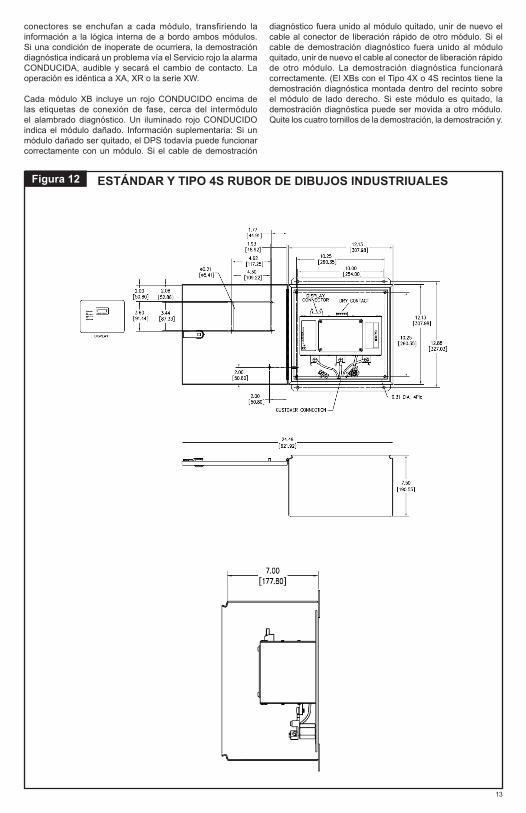
conectores se enchufan a cada módulo, transfiriendo la información a la lógica interna de a bordo ambos módulos. Si una condición de inoperate de ocurriera, la demostración diagnóstica indicará un problema vía el Servicio rojo la alarma CONDUCIDA, audible y secará el cambio de contacto. La operación es idéntica a XA, XR o la serie XW.
Cada módulo XB incluye un rojo CONDUCIDO encima de las etiquetas de conexión de fase, cerca del intermódulo el alambrado diagnóstico. Un iluminado rojo CONDUCIDO indica el módulo dañado. Información suplementaria: Si un módulo dañado ser quitado, el DPS todavía puede funcionar correctamente con un módulo. Si el cable de demostración
diagnóstico fuera unido al módulo quitado, unir de nuevo el cable al conector de liberación rápido de otro módulo. Si el cable de demostración diagnóstico fuera unido al módulo quitado, unir de nuevo el cable al conector de liberación rápido de otro módulo. La demostración diagnóstica funcionará correctamente. (El XBs con el Tipo 4X o 4S recintos tiene la demostración diagnóstica montada dentro del recinto sobre el módulo de lado derecho. Si este módulo es quitado, la demostración diagnóstica puede ser movida a otro módulo. Quite los cuatro tornillos de la demostración, la demostración y.
13
Figura 12 ESTÁNDAR Y TIPO 4S RUBOR DE DIBUJOS INDUSTRIUALES

14
MONTAJE DE RUBOR Y SCREWCOVER PULLBOX DIBUJOS INDUSTRIUALES
TIPO 4X DIAGRAMAS MECÁNICOS NO METÁLICOS
Figura 13
Figura 14
21.62 [549.25]
20.75 [527.05]
20.00 [508.00]
18.25 [463.55]
14.00 [355.60]
20.00 [508.00]
18.00 [457.20]
18.25 [463.55]
19.38 [492.14]
0.31 DIA. 4Plc
A B C N
A
G
Advanced Protection Technologies, Inc.Clearw
ater, FloridaListed
56E3
TVSSU
RL
CAUTION
2
13
46
57
8
DRY CO
NTAC
T
Adv
ance
d Pr
otec
tion
Tech
nolo
gies
, Inc
.Cl
earw
ater
, Flo
rida
List
ed
56E3
TVSS
U RL
CAUT
ION
B CN
A B CN
15.25 [387.35]
15.25 [387.35]
22.00 [558.80]
16.75 [425.45]
16.69 [423.88]
22.00 [558.80]
14.00 [355.60]
4.00 [101.60]
4.00 [101.60]
19.38 [492.13]
1.31 [33.34]
1.31 [33.34]
�0.25 [�6.35]
1.00 [25.40]
1.00 [25.40]
Ph
ase
C
Se
rvice
Ph
ase
B
Ph
ase
AS
urg
e C
ou
nte
r
CUSTOMER CONNECTION
DISPLAY CO
NN
ECTO
R
17.62 [447.65]
16.75 [425.45]
16.00 [406.40]
14.25 [361.95]
10.00 [254.00]
14.00 [355.60]
12.00 [304.80]
12.25 [311.15]
13.38 [339.74]
0.31 DIA. 4Plc
2
13
46
57
8
DISPLAY CONNECTORDRY CONTACT
Advanced Protection Technologies, Inc.Clearwater, Florida
Listed
56E3
TVSSURL
C B A N
G
OPTIONAL DISCONNECT
CUSTOMER CONNECTION
CAUTION
16.00 [406.40]
10.75 [273.05]
12.69 [322.28]
18.00 [457.20]
10.00 [254.00]
4.00 [101.60]
4.00 [101.60]
13.38 [339.73]
1.31 [33.34]
1.31 [33.34]
�0.25 [�6.35]
1.00 [25.40]
1.00 [25.40]
Ph
ase
C
Se
rvice
Ph
ase
B
Ph
ase
AS
urg
e C
ou
nte
r
13.62 [346.05]
12.75 [323.85]
12.00 [304.80]
10.25 [260.35]
6.00 [152.40]
12.00 [304.80]
10.00 [254.00]
10.25 [260.35]
11.38 [288.94]
0.31 DIA. 4Plc
2
13
46
57
8
C B A N
DISPLAY CONNECTORDRY CONTACT
Advanced Protection Technologies, Inc.Clearwater, Florida
Listed
56E3
TVSSURLG
OPTIONAL DISCONNECT
CUSTOMER CONNECTION
CAUTION
14.00 [355.60]
8.75 [222.25]
8.69 [220.68]
14.00 [355.60]
6.00 [152.40]
4.00 [101.60]
4.00 [101.60]
11.38 [288.93]
1.31 [33.34]
1.31 [33.34]
1.00 [25.40]
1.00 [25.40]
Ph
ase
C
Se
rvice
Ph
ase
B
Ph
ase
AS
urg
e C
ou
nte
r
20”x20” 16”x14” 12”x12”9.8810.2511.96
16.0113.96
12.25
12.58
14.58
11.03
16.95
5.966.30
7.136.37
0.30
14” x 12”
22.0121.0019.25
25.56
19.2521.00
8.947.61
27.06
24.11
24” x 24”
16” x 14”
12.1312.2513.97
17.59
15.96
14.70
14.25
13.28
16.70
16.65
6.787.12
7.95
7.307.48
24”x24”
16”x14”
14”x12”
Para dibujos de mejor visualización visite: surge.ascopower.com