Embed Size (px)
Citation preview

Copyright WILEY-VCH Verlag GmbH & Co. KGaA, 69469 Weinheim, Germany, 2012.
Supporting Information for Adv. Mater., DOI: 10.1002/adma.201202932 Plasmid-Templated Shape Control of Condensed DNA–Block Copolymer Nanoparticles Xuan Jiang, Wei Qu, Deng Pan, Yong Ren, John-Michael Williford, Honggang Cui, Erik Luijten,* and Hai-Quan Mao*

Submitted to
1
SUPPORTING INFORMATION
Plasmid-Templated Shape Control of Condensed DNA–Block
Copolymer Nanoparticles
Xuan Jianga,b,#
, Wei Quc,#
, Deng Pand, Yong Ren
a,b, John-Michael Williford
d, Honggang Cui
e,
Erik Luijten c,f,1
, Hai-Quan Mao
a,b,1
aDepartment of Materials Science and Engineering, Whiting School of Engineering, Johns
Hopkins University, Baltimore, Maryland 21218, USA;
bTranslational Tissue Engineering Center and Whitaker Biomedical Engineering Institute, Johns
Hopkins School of Medicine, Baltimore, Maryland 21287, USA;
cDepartment of Materials Science and Engineering, Northwestern University, Evanston, Illinois
60208, USA;
dDepartment of Biomedical Engineering, Johns Hopkins School of Medicine, Baltimore,
Maryland 21205, USA;
eDepartment of Chemical and Biomolecular Engineering, Whiting School of Engineering, Johns
Hopkins University, Baltimore, Maryland 21218, USA;
fDepartment of Engineering Sciences and Applied Mathematics, Northwestern University,
Evanston, Illinois 60208, USA.
#These authors contributed equally to this work.
1To whom correspondence should be addressed.
Email: [email protected] and [email protected]

Submitted to
2
1. Self-assembly of PEG-b-PPA/DNA Micellar Nanoparticles
1.1. Synthesis of PEG10K-b-PPA4K block copolymer and PPA-DPA
PEG10K-b-PPA4K polymer was synthesized through ring-opening coordination
polymerization (Fig. S1). Methoxy-polyethylene (mPEG, MW 9.5 kDa, 1.9 g, 0.2 mmol) was
first dried by azeotropic distillation in toluene to remove water associated with the PEG chains
and then incubated with equal amount of triisobutylaluminum in 20 ml of dichloromethane for
1 h. The polymerization of 4-alkyl-2-oxo-2-hydro-1,3,2-dioxaphospholane was initiated by
injecting 5.3 g (43 mmol) of monomer into initiator solution pre-cooled in an ice bath. The
mixture was stirred at 0°C for 48 h. Precursor Polymer 1 was obtained by removing solvent
under vacuum at room temperature and subsequently dissolved in 40 ml of anhydrous DMF
under argon. To this solution was added 37.8 g (86 mmol) of
N1,N
9-bis(trifluoroacetyl)dipropyltriamine (TFA-DPA) [S1], followed by addition of 48.0 ml
(340 mmol) of anhydrous triethylamine and 33.3 ml (340 mmol) of anhydrous CCl4. The mixture
was stirred at 0°C for 30 min, then at room temperature for 24 h. The reaction mixture was
Figure S1. Synthesis scheme of PEG-b-PPA. The number average molecular weights of PEG and PPA
blocks were 9.5 kDa and 4.15 kDa, respectively. The grafting density p can be controlled in a range of
50% to 70%.

Submitted to
3
precipitated into ether and dried under vacuum to yield Precursor Polymer 2, which was then
resuspended in 25% ammonia solution and stirred at 60°C for 16 h. The solution was
concentrated and dialyzed in dialysis tubing (MWCO 3500, Spectrapor, Spectrum Labs, CA)
against distilled water for 2 days. The unreacted mPEG was removed by ion-exchange column
(Sephadex C25, Sigma) using DI water as an eluent. Sodium hydroxide (0.1 mol/l) was used to
elute the PEG-b-PPA polymer. The PEG-b-PPA was obtained after neutralization, dialysis, and
lyophilization (yield 30–40%).
PPA-DPA polymer was synthesized according to our previous report [S2]. The molecular
weights of PEG-b-PPA and PPA-DPA polymers were determined using an Agilent 1200 Series
Isocratic LC System coupled with a multi-angle light scattering detector (MiniDawn, Wyatt
Technology, Santa Barbara, CA). A dn/dc value of 1.4 was used for all PEG-b-PPA samples.
Sodium acetate buffer (HAc-NaAc 0.5 M, pH 4.8) was used as the mobile phase (flow rate
0.5 ml/min). The 1H-NMR spectra were recorded on a Bruker 400 MHz NMR (Bruker, Billerica,
MA). The grafting degree of DPA for PEG-b-PPA and PPA-DPA polymers was obtained by
comparing the integral of peaks at δ 1.1–1.4 ppm (CH3- in the backbone) and δ 1.9–2.0 ppm
(-CH2CH2CH2- in the grafted side chains). The structural characteristics of PEG-b-PPA and
PPA-DPA (hereafter referred to as PPA) polymers are listed in Table S1.
Table S1. Structural characteristics of PEG10K-b-PPA4K and PPA-DPA polymers.
Polymer carrier PEG10K-b-PPA4K PPA-DPA4K[a]
Mn 13,650 4,400
Polydispersity 1.08 1.64
Mn of PEG block 9,500 N.A.
Mn of PPA block 4,150 4,400
Grafting degree of DPA (%) 54.3 54.7
[a] Hereafter referred to as PPA4K.

Submitted to
4
1.2. Amplification and purification of plasmid DNA
VR1255C plasmid DNA (6.4 kb) encoding firefly luciferase driven by cytomegalovirus
promoter was provided as a gift by Vical (San Diego, CA). The plasmid DNA was amplified in
E. coli DH5 and purified with a QIAGEN EndoFree Giga kit (QIAGEN, Valencia, CA).
1.3. Preparation of PEG10K-b-PPA4K/DNA micelles in DMF‒water mixtures
For a typical preparation, VR1255 plasmid DNA (25 g) was first dissolved in 250 l DI
water or dimethylformamide (DMF)–water mixtures with different DMF to water volumetric
ratios ranging from 0:1, 3:7, 5:5 to 7:3 (v/v). PEG10K-b-PPA4K polymer (340.6 g, corresponding
to an N/P ratio of 8) was also dissolved in 250 l DI water or DMF–water mixture at the same
DMF fraction. This N/P ratio was selected based on our previous report [S3] showing optimal
transfection efficiency at this ratio. To obtain PEG10K-b-PPA4K/DNA micelles with different
morphologies, plasmid DNA solution was added into PEG10K-b-PPA4K polymer solution and the
mixture was vortexed for 30 s. The mixture was then incubated at room temperature for 24 h
before characterization.
1.4. Transmission electron microscopy (TEM)
Samples were prepared by depositing 10 µl of PEG10K-b-PPA4K/DNA micelle solution on a
freshly ionized nickel grid covered by a carbon film. After 10 min, excess liquid was blotted
away with filter paper. A drop of 2% uranyl acetate solution (~1 l) was then deposited on the
nickel grid. After drying at room temperature, the samples were examined on a Tecnai FEI-12
electron microscope.
1.5. Cryogenic TEM (Cryo-TEM)
To prepare samples for Cryo-TEM, 5–10 μl of micelle solution was placed on a holey
carbon film supported on a TEM copper grid (SPI Supplies, West Chester, PA). Following the
preset procedure of the FEI Vitrobot vitrification system (FEI Company, Hillsboro, OR), the
specimen was blotted and plunged into a liquid ethane reservoir cooled by liquid nitrogen. The
vitrified samples were transferred to a Gatan 626 cryoholder and cryo-transfer stage cooled by
liquid nitrogen. The specimens were then examined on an FEI Tecnai 12 microscope using a

Submitted to
5
Gatan cryo-holder system. During observation of the vitrified samples, the cryo-holder
temperature was maintained at less than –165°C to prevent sublimation of vitreous water. The
images were captured digitally by a Gatan low-dose CCD camera. Fig. S2 shows that the
dimensions and morphologies of these micelles obtained by cryo-TEM imaging agreed well with
those obtained with regular TEM (Fig. 1B‒E).
Figure S2. Cryo-TEM images of PEG10K-b-PPA4K/DNA micelles prepared in deionized (DI) water (A) and
crosslinked PEG10K-b-PPA4K/DNA micelles (B–D) prepared in DMF–water mixture solvent at an N/P ratio
of 8. Crosslinked micelles with different shapes were prepared using thiolated PEG10K-b-PPA4K under the
same condition as described in Fig. 1 and then crosslinked by aerial oxidation for 48 h, after which DMF
was removed from the solution by dialysis against DI water. Cryo-TEM images of the crosslinked micelles
initially obtained in DI water (B), 5:5 (v/v) (C), and 7:3 (v/v) (D) DMF‒water mixtures. All scale bars
represent 200 nm.

Submitted to
6
1.6. Preparation of PEG10K-b-PPA4K/DNA micelles in DMSO‒water mixtures
These micelles were prepared according to the same procedure as described in Section 1.3,
except that DMF was replaced with DMSO. Fig. S3 shows the same series of shape changes as
those illustrated in Fig. 1. Worm-like and ring-like micelles were obtained in water (Fig. 1B) and
DMSO‒water (3:7, v/v) (Fig. S3A), short rod-like micelles in DMSO‒water (5:5, v/v) (Fig.
S3B) and spherical micelles in DMSO‒water (7:3, v/v) mixtures (Fig. S3C).
Figure S3. Morphologies of PEG10K-b-PPA4K/DNA micelles prepared in 3:7 (v/v) (A), 5:5 (v/v) (B), and 7:3
(v/v) (C) DMSO‒water mixture solvent at an N/P ratio (ratio of primary amino groups in PPA block of the
copolymer to phosphate groups in DNA) of 8. The micelle solutions were incubated at room temperature
for 24 h and then processed for TEM imaging. All scale bars represent 200 nm. These micelles exhibited
morphologies similar to those of micelles obtained in DMF–water mixtures at the same mixing ratios.

Submitted to
7
1.7. Effect of solvent polarity on plasmid DNA morphology
VR1255 plasmid DNA (10 g) was dissolved in 100 l DMF‒water mixture at different
DMF/water volumetric ratios ranging from 1:9 to 7:3. The morphologies of plasmid DNA in
DMF‒water mixtures with different DMF/water volumetric ratios were then characterized by
TEM (Fig. S4).
Figure S4. Effect of solvent polarity on the conformation of plasmid DNA in 1:9 (v/v) (A), 3:7 (v/v) (B),
5:5 (v/v) (C), and 7:3 (v/v) (D) DMF–water mixture. The scale bars represent 200 nm. With increasing
DMF fraction, plasmid DNA molecules formed more condensed structures with some sizes smaller than
100 nm. However, large aggregates of plasmid DNA molecules with sizes above 200 nm were frequently
observed as well.

Submitted to
8
1.8. Effect of solvent polarity on the shape of PPA4K/DNA nanoparticles
VR1255 plasmid DNA (10 g) was first dissolved in 100 l DI water or DMF–water
mixture at different DMF/water volumetric ratios. PPA4K polymer (44.6 g, corresponding to an
N/P ratio of 8) was also dissolved in 100 l DI water or DMF–water mixture at the same DMF
fraction. PPA4K/DNA nanoparticles were prepared by adding plasmid DNA solution into PPA4K
solution. The mixture was vortexed for 30 s and incubated at room temperature for 2 h. The
morphologies of PPA4K/DNA nanoparticles in DMF–water mixtures with different DMF
fractions were then characterized by TEM (Fig. S5). As seen in the TEM images, spherical and
irregularly shaped particles were obtained under all solvent conditions examined, with
aggregates observed at higher DMF fraction. No particles with higher aspect ratios were
observed, highlighting the importance of PEG segments in controlling the shapes of PEG-b-
PPA/DNA micelles.
Figure S5. Effect of DMF fraction on the morphology of PPA4K/DNA nanoparticles. PPA4K/DNA
nanoparticles were prepared in DI water (A) and 3:7 (v/v) (B), 5:5 (v/v) (C), and 7:3 (v/v) (D) DMF‒water
mixture. All scale bars represent 200 nm.

Submitted to
9
2. Computational Methods
2.1 Simulation model
The LAMMPS package was used to perform large-scale molecular dynamics simulations
[S4]. In the simulations, the DNA and the PEG-b-PPA copolymers were represented by a bead–
spring model with a harmonic bond potential,
, (1)
where r is the center-to-center distance between two beads connected by a bond and r0 = 21/6,
with the Lennard-Jones (LJ) unit of length and the LJ unit of energy. In light of
computational efficiency, the plasmid DNA was represented by a bead–spring ring polymer of
80 beads, in which each bead had an electrostatic valency of –1. To represent the characteristic
charge pattern of the PPA block, we simulated the PPA block as 3 beads with charges (+2, +2,
1), i.e., a grafting density of 67%, corresponding to the upper limit of the grafting density in the
experiments. The length of the PEG block in the simulation was chosen as 10 beads, all of which
were neutral.
Whereas the copolymers were considered fully flexible, an additional harmonic bond-angle
potential was applied to the DNA to represent its intrinsic stiffness,
, (2)
where θ is the angle between two adjacent bonds and θ0 = 180°. With this bond stiffness, the
intrinsic persistence length of the DNA is 6.8, as determined from the exponential decay length
of the bond-angle correlation function of a neutral, linear polymer with the same bond-angle
potential [S5]. As a result, the ratio of the intrinsic persistence length to the contour length is
approximately three times larger than in the experiments, which we consider acceptable given
the simplifications adopted in this semi-quantitative model.
The solvent was simulated implicitly using a Langevin thermostat with damping time 100,
where is the LJ unit of time,
, (3)
2
bond 0200U r r
2
angle 04U
2m

Submitted to
10
in which m is the LJ unit of mass. The equations of motion were integrated using the velocity-
Verlet algorithm. The temperature was controlled by the Langevin thermostat as well, and set to
T = 1.2/kB, where kB is Boltzmann’s constant. Following Ref. [S6], the Bjerrum length in water
was chosen to be equal to 3. As the solvent changes from pure water to DMF–water mixtures at
different proportions, the dielectric constant increases (cf. Table S2). At the same time, the
charge density of the plasmid DNA decreases with increasing DMF fraction [17], as reflected by
the potential in Table S2.
Table S2. Dielectric constant and potential of plasmid DNA for pure water and for DMF–water mixtures
Solvent Condition Dielectric Constant [S7] potential (mV) [17]
Water 79.5 –64
DMF–water (30:70, v/v) 75.0 –58
DMF–water (50:50, v/v) 67.9 –58
DMF–water (70:30, v/v) 57.0 –53
Although the DNA conformation and the mixed nature of the solvent complicate a precise
calculation of the surface charge from the potential, it is reasonable to employ the
approximation (although strictly valid only for low potential) that surface charge and
potential are linearly proportional [S8]. Then, if we also assume that the surface charges on DNA
and PPA respond similarly to solvent variation, the variation in surface charge counteracts the
variation in dielectric constant and the electrostatic interaction between DNA and PPA blocks
varies by only ~5% over the range of DMF/water volumetric ratios tested (with an outlier of 13%
for a 3:7 (v/v) DMF–water mixture). Thus, for simplicity we assumed a constant Bjerrum length
and constant charge density in our model.
As the DMF concentration increases, the solvent quality for DNA and PPA systematically
decreases. Since we employed an implicit solvent, the change from a good to a poor solvent was
represented by an increase in the effective attraction between DNA repeat units and between
PPA repeat units. Since the PPA blocks and DNA already experience a strong electrostatic
interaction, no additional solvent-induced effective attraction between DNA and PPA was
imposed. When selecting the relative magnitude of the DNA–DNA attraction and the PPA–PPA

Submitted to
11
attraction, it must be taken into account that the number of DNA monomers represented by a
single DNA bead in the simulations is approximately three times larger than the number of PPA
monomers represented by a PPA bead. Consequently, the number of DNA–solvent contacts (per
bead in the simulation) is approximately three times larger than the number of PPA–solvent
contacts. To reflect this, we set the attraction between PPA units in the poorest solvent
(Solvent 4) to one third of the attraction between DNA units. In the coarse-grained modeling
adopted here, it was our aim to elucidate the mechanism of micelle shape variation, rather than to
realize a precise mapping between different DMF/water ratios onto attractive pair potentials.
Thus, we opted to describe this pair potential via a LJ potential with gradually increasing
attractive strength. Since attraction strengths above 3kBT are likely to result in a kinetically
arrested situation, we chose the four solvents to linearly interpolate between 1kBT and 3kBT for
the DNA repeat units. For PPA repeat units, we thus chose the attraction strength in Solvent 4 to
be 1kBT, which was then decreased linearly to a potential without attraction (i.e., a purely
repulsive shifted-truncated LJ potential) in Solvent 1. Given our choice for the temperature, this
yielded the parameters listed in Table S3. The pair potential was cut off at 2.5 and shifted at
the cutoff to eliminate a discontinuity in the interaction, except for PPA in Solvent 1, for which a
Table S3. Effective attraction strength LJ (in units of the LJ energy parameter ) between DNA units
and PPA units for different solvent conditions. With increasing DMF fraction, the solvent quality
decreases, represented by an increase in LJ. Since the simulations take place at a temperature
T = 1.2/kB, an attraction strength LJ = 1.2 corresponds to 1kBT and LJ = 3.6 corresponds to
3kBT.
Solvent Condition LJ / (DNA) LJ / (PPA)
Solvent 1 1.2 Purely repulsive
Solvent 2 2.0 0.4
Solvent 3 2.8 0.8
Solvent 4 3.6 1.2
Submitted to
12
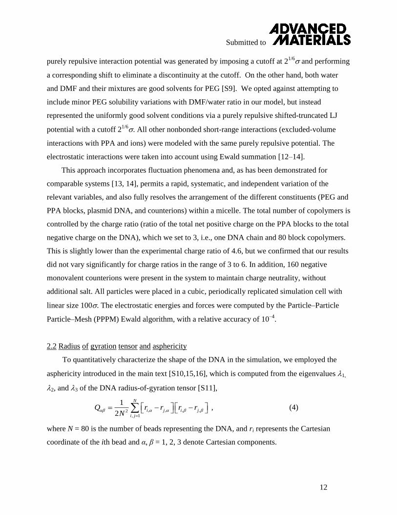
purely repulsive interaction potential was generated by imposing a cutoff at 21/6 and performing
a corresponding shift to eliminate a discontinuity at the cutoff. On the other hand, both water
and DMF and their mixtures are good solvents for PEG [S9]. We opted against attempting to
include minor PEG solubility variations with DMF/water ratio in our model, but instead
represented the uniformly good solvent conditions via a purely repulsive shifted-truncated LJ
potential with a cutoff 21/6. All other nonbonded short-range interactions (excluded-volume
interactions with PPA and ions) were modeled with the same purely repulsive potential. The
electrostatic interactions were taken into account using Ewald summation [12–14].
This approach incorporates fluctuation phenomena and, as has been demonstrated for
comparable systems [13, 14], permits a rapid, systematic, and independent variation of the
relevant variables, and also fully resolves the arrangement of the different constituents (PEG and
PPA blocks, plasmid DNA, and counterions) within a micelle. The total number of copolymers is
controlled by the charge ratio (ratio of the total net positive charge on the PPA blocks to the total
negative charge on the DNA), which we set to 3, i.e., one DNA chain and 80 block copolymers.
This is slightly lower than the experimental charge ratio of 4.6, but we confirmed that our results
did not vary significantly for charge ratios in the range of 3 to 6. In addition, 160 negative
monovalent counterions were present in the system to maintain charge neutrality, without
additional salt. All particles were placed in a cubic, periodically replicated simulation cell with
linear size 100. The electrostatic energies and forces were computed by the Particle–Particle
Particle–Mesh (PPPM) Ewald algorithm, with a relative accuracy of 10–4
.
2.2 Radius of gyration tensor and asphericity
To quantitatively characterize the shape of the DNA in the simulation, we employed the
asphericity introduced in the main text [S10,15,16], which is computed from the eigenvalues 1,
2, and 3 of the DNA radius-of-gyration tensor [S11],
, (4)
where N = 80 is the number of beads representing the DNA, and ri represents the Cartesian
coordinate of the ith bead and α, β = 1, 2, 3 denote Cartesian components.
, , , ,2, 1
1
2
N
i j i j
i j
Q r r r rN

Submitted to
13
2.3 Equilibration of the simulations and the use of parallel tempering
The DNA chain, the copolymers, and the counterions initially were randomly placed in the
simulation box. To accelerate the equilibration process, initially a shifted and truncated LJ
interaction with cutoff 21/6 was used as the only pairwise interaction between any two particles.
After an equilibration period of 3 103 with time step 0.01, the proper LJ interactions and all
electrostatic interactions were switched on, followed by a second equilibration period of
2.4 103. As shown in Fig. S6, the structure of the DNA fluctuates between different states.
However, in a single run, the switching occurs relatively infrequently, which makes it difficult to
obtain an accurate probability distribution for the asphericity. To accelerate the fluctuation
between different states, we employed the parallel tempering method [S12]. In this approach,
multiple copies of the same system are simulated in parallel, at different temperatures. At fixed
intervals, an exchange between configurations simulated at adjacent temperatures is attempted.
This approach exploits the larger degree of fluctuations at higher temperatures to provide a
pathway for the simulations at the original temperature to transition between states. With
increasing interaction strength (decreasing solvent quality), transitions became progressively
more difficult and a larger number of parallel simulations were required. The details for the
parallel tempering runs are listed in Table S4. The temperatures were distributed logarithmically
over the interval indicated. Three parallel tempering runs were performed for each solvent, for a
sampling period of at least 7.2 105 per run.
Table S4. Simulation details of parallel tempering for different solvent conditions. The number of partitions
represents the number of different temperatures at which the system is simulated simultaneously.
Solvent Condition Temperature range
/ (/kB) Number of partitions
Time step /
Exchange interval / step
Solvent 1 1.2 to 1.6 12 0.012 4000
Solvent 2 1.2 to 1.8 52 0.012 4000
Solvent 3 1.2 to 2.4 80 0.010 4800
Solvent 4 1.2 to 2.8 92 0.008 6000

Submitted to
14
Figure S6. Time evolution of the asphericity of DNA within a PEG-b-PPA/DNA micelle in Solvents 1–4
(top to bottom) obtained in a serial run (labeled SR, left-hand column) and via parallel tempering (labeled
PT, right-hand column).

Submitted to
15
2.4 Effect of PEG blocks
Fig. S7 shows the frequency distribution of the asphericity of the plasmid DNA within a
PPA/DNA complex (i.e., DNA complexed with a PPA homopolymer) and within a PEG-b-
PPA/DNA micelle in each of the four different solvents. For DNA condensed with PPA
homopolymers, the asphericity peak associated with elongated conformations is absent,
demonstrating that without the excluded-volume effect of the PEG blocks, the micelle could not
assume an elongated conformation. Furthermore, in Solvents 1–3 the peak corresponding to the
toroidal structure is significantly broader for DNA condensed with PPA alone than for DNA
condensed with PEG-b-PPA copolymers, reflecting stronger structural fluctuations of the
PPA/DNA complexes. This reinforces our conclusions regarding the crucial role of the PEG
blocks in controlling the shape and uniformity of the micelles.

Submitted to
16
Figure S7. (A–D) Frequency distribution of DNA asphericity in PPA/DNA complexes and in PEG-b-
PPA/DNA micelles in Solvent 1 (A), Solvent 2 (B), Solvent 3 (C), and Solvent 4 (D). Panels (E–H) show
representative images obtained from molecular dynamics simulations of the condensation of plasmid DNA
with PPA4K polymer in Solvent conditions 1 through 4, similar to those discussed in Figs. 1 and 2. Panels
(I–L) show the same images, in which all PPA segments and counterions have been omitted for clarity.

Submitted to
17
3. Transformation of Micelle Shape by Titrating Solvent Polarity
PEG10K-b-PPA4K/DNA micelles were first prepared in the presence of 7:3 (v/v) DMF–water
mixture as described in Section 1.6. DI water was gradually titrated into 500 μl of micelle
solution with a syringe pump at a rate of 1 ml/h under stirring. At different DMF fractions, an
aliquot of micelle solution was incubated at room temperature for 24 h and processed for TEM
imaging (Fig. 3). TEM images were analyzed with Image J 1.43. The lengths or diameters of
each individual micelle were measured, and the average diameters and standard deviations were
calculated from the measurements of 80 to 100 micelles in each sample.
4. Stabilization of Micelle Shapes and Gene Delivery In Vivo
4.1. Preparation of thiolated PEG10K-b-PPA4K carrier
PEG10K-b-PPA4K polymer (10 mg) was dissolved in 75 mM, pH 8.0 PBS buffer (purged
with argon to remove dissolved oxygen) to achieve a concentration of 20 mg/ml. Traut’s reagent
(0.45 mg) dissolved in DI water at a concentration of 10 mg/ml was mixed with PEG10K-b-
PPA4K polymer solution and reacted for 2 h at room temperature (Fig. S8). The reaction mixture
was then dialyzed against 2 mM EDTA solution (purged with argon) for 1 h through a dialysis
membrane with MWCO of 3,500 Da. The final product was obtained after lyophilization. The
grafting degree of free thiol groups was determined to 18.9% by using 4-(amino-sulfonyl)-7-
fluoro-2,1,3-benzoxadiazole (ABD-F) reagent according to a reported method [S13].
Figure S8. Reaction scheme for preparing thiolated PEG10K-b-PPA4K copolymer carrier.

Submitted to
18
4.2. Preparation of micelles with different shapes with thiolated PEG10K-b-PPA4K
To compare the shapes and sizes of uncrosslinked micelles with those shown in Fig. 4,
thiolated PEG10K-b-PPA4K/DNA micelles were prepared in 7:3 (v/v), 5:5 (v/v), 4:6 (v/v),
and1:9 (v/v) DMF–water mixtures using the same protocol as described in Fig. 4. An aliquot of
micelle solution was processed for TEM analysis after 24 hours of incubation (Fig. S9). These
thiolated PEG10K-b-PPA4K/DNA micelles prepared at different DMF concentrations exhibited
similar particle size and shapes as their crosslinked counterparts shown in Fig. 4.
4.3. Crosslinking of thiolated PEG10K-b-PPA4K/DNA micelles with different shapes
The thiolated PEG10K-b-PPA4K was then used for the preparation of micelles in the presence
of 7:3 (v/v) DMF–water mixture. To transform the morphology of thiolated PEG10K-b-
PPA4K/DNA micelles, DI water was titrated into micelle solution as described in Section 3.
After transformation, the micelles were incubated at room temperature for 24 h and then
subjected to aerial oxidation for 48 h under stirring (Fig. S10). DMF was then removed by
Figure S9. Morphologies of thiolated PEG10K-b-PPA4K/DNA micelles before crosslinking. Micelles with
different shapes were prepared using thiolated PEG10K-b-PPA4K in 7:3 (v/v) (A), 5:5 (v/v) (B), 4:6 (v/v) (C),
and 1:9 (v/v) (D) DMF–water mixtures under the same conditions as described in Fig. 4. All scale bars
represent 200 nm.

Submitted to
19
dialyzing the micelle solution against DI water using dialysis tubing with MWCO of 3,500 for
another 24 h. The TEM images of crosslinked PEG10K-b-PPA4K/DNA micelles with different
morphologies (Fig. 4A–D) were analyzed with Image J 1.43.
Figure S10. Preparation steps of crosslinked PEG10K-b-PPA4K/DNA micelles by aerial oxidation (left).
The disulfide crosslinks can be reduced in the presence of high concentrations of glutathione found in
the cytosol or nucleus. This process can then facilitate the release of DNA from the micelles (right).

Submitted to
20
4.4. Stability of crosslinked PEG10K-b-PPA4K/DNA micelles
To evaluate the stability of micelles in the presence of salts at physiological concentration, a
calculated amount of NaCl solution (5 M) was added to micelles with various shapes prepared
and crosslinked under the same condition as described in Fig. 4, to adjust the concentration of
NaCl to 0.15 M. After incubation with NaCl for 30 minutes, an aliquot of micelle solution was
processed for TEM analysis (Fig. S11). No micelles showed a significant change in particle size
or morphology, indicating that they were insensitive to electrostatic screening.
To assess the stability of crosslinked micelles in the presence of serum, we selected
crosslinked, spherical, and worm-like micelles and incubated them in 5% (v/v) fetal bovine
serum at 37°C for 1 h. An aliquot of micelle solution was then analyzed by TEM using the same
method as described above. As shown in Fig. S12A–D, both spherical and worm-like micelles
retained their original size and morphology upon incubation in serum-containing medium. In
contrast, PPA4K/DNA nanoparticles aggregated severely under the same condition (Fig. S12F).
Figure S11. TEM images of crosslinked PEG10K-b-PPA4K/DNA micelles initially prepared in 7:3 (v/v) (A),
5:5 (v/v) (B), 4:6 (v/v) (C), and 1:9 (v/v) (D) DMF–water mixtures, followed by incubation in 0.15 M NaCl
for 30 min. All scale bars represent 500 nm.

Submitted to
21
These results demonstrate that the crosslinked micelles exhibit much higher colloidal stability
and are capable of maintaining micelle size and morphology in serum-containing medium.
Furthermore, to determine whether crosslinked micelles can protect encapsulated DNA from
enzymatic degradation in serum, we incubated crosslinked micelles in 10% (v/v) fetal bovine
serum at 37°C for 4 h. Subsequently, DTT and heparin were added to micelle solutions to
resolve the disulfide crosslinks and release the encapsulated DNA for assessment of its integrity.
Figure S12. TEM images of crosslinked PEG10K-b-PPA4K/DNA micelles initially prepared in
1:9 (v/v) (A and B) and 7:3 (v/v) (C and D) DMF–water mixtures, followed by incubation in
5% (v/v) fetal bovine serum for 60 min at 37°C. Images for the same set of micelles prior to
incubation in serum-containing medium are shown in Fig. S11D and S11A, respectively. Also
shown are PPA4K/DNA nanoparticles before (E) and after (F) incubation in 5% (v/v) serum under
the same conditions. Image (F) reveals severe aggregation.

Submitted to
22
An aliquot of micelle solution was analyzed by electrophoresis on a 0.8 w/v% agarose gel for 45
min at 75 V. The results are shown in Fig. S13. On the gel, degradation of plasmid DNA was
observed after incubation for only 15 min, as indicated by a long smear band; a 2-h incubation
with 10% (v/v) serum yielded nearly completely degraded plasmid DNA (Lane 10). In contrast,
DNA recovered from crosslinked spherical (Lane 2) and worm-like micelles (Lane 4), which
were incubated in 10% (v/v) serum at 37C for 4 h, showed migration patterns similar to DNA
samples recovered from micelles that were not incubated with serum (Lanes 3 and 5,
respectively). By comparing Lanes 3, 5, and 6, it is obvious that the DNA recovering process
was not fully efficient and that there was some difference in DNA release ability between
spherical and worm-like micelles. But it is also clear that crosslinked micelles protected
encapsulated DNA from degradation, as DNA samples recovered from micelles incubated in
Figure S13. Stability of crosslinked PEG10K-b-PPA4K/DNA micelles with different morphologies in the
presence of serum characterized with gel electrophoresis. Lane 1: DNA ladder, Lanes 2 and 4: spherical
and worm-like micelles (crosslinked PEG10K-b-PPA4K/DNA micelles obtained in 7:3 (v/v) and 1:9 (v/v)
DMF–water mixtures, respectively) incubated in 10 v/v% fetal bovine serum (FBS) at 37°C for 4 h, and
then treated with 1 M DTT, 8 mg/mL heparin, and 20 mM EDTA at 37°C for 3 h to release encapsulated
DNA. Lanes 3 and 5: spherical and worm-like micelles without incubation in serum-containing medium
were treated similarly with DTT, heparin and EDTA to release encapsulated DNA. Lanes 6–10: VR1255
plasmid DNA incubated in 10 v/v% FBS for 0 min, 15 min, 30 min, 1 h, and 2 h, respectively. Smear
bands in lanes 7–9 indicate severe degradation, whereas DNA in Lane 10 is nearly completely degraded.

Submitted to
23
serum-containing medium (Lanes 2 and 4) were free from low-molecular-weight DNA
fragments like those shown in Lanes 7 through 10. These results confirm that the micelles
provided a high level of protection to the encapsulated DNA against degradation in serum-
containing medium.
4.5. In vivo transfection efficiency of crosslinked PEG10K-b-PPA4K/DNA micelles with different
shapes via intrabiliary infusion
Animal studies were conducted under an animal protocol that was approved by the Johns
Hopkins School of Medicine Institutional Animal Care and Use Committee (IACUC
#RA09A447). Female Wistar rats aged 6–8 weeks (200–300 g) were anesthetized with
intraperitoneal injection of Ketamine (100 mg/kg) and Xylazine (10 mg/kg). A 33-gauge needle
was inserted into the common bile duct and the needle was secured by tie around the common
bile duct. Four ml of crosslinked PEG10K-b-PPA4K/DNA micelles with different shapes
containing 20 µg VR1255 DNA in 5% glucose solution were infused through the bile duct over
20 min with a syringe pump. A tie was then placed around the bile duct between the liver and
the point of infusion to prevent back flow before the needle was withdrawn. Occasionally,
stitches with 10-O nylon (Ethicon, Somerville, NJ) were needed to repair the needle hole in the
bile duct to prevent bile leakage.
After intrabiliary infusion, the luciferase expression level in rat liver was characterized with
Bioluminescence (BLI). BLI has been shown as a highly sensitive analysis technique for the
determination of luciferase expression in situ [S14]. Moreover, Rettig et al. have reported an
excellent linear relationship between in situ BLI measurement of the luciferease expression
levels and chemiluminscence measurement in liver homogenates over a wide range of luciferase
expression (from 10 pg to 5 × 10⁵ pg luciferase per liver) [S15]. Combined with the ease and
non-invasiveness of this analysis method, and the ability to monitor transgene expression in the
same experimental animal over an extended period of time, this method has been widely adopted
as an attractive alternative to the chemiluminescence assay. As a preliminary test, we compared
the transgene of luciferase at 4 h after intrabiliary infusion. Rats were anesthetized and 1 ml of
D-luciferin solution (30 mg/mL) was injected intraperitoneally. The rats were then transferred

Submitted to
24
from the box to the nose cones attached to the manifold in the imaging chamber of an IVIS
Spectrum Imaging System. The rats were positioned with abdomen side up. After 5 min, the
bioluminescence signals of the rats were imaged and recorded for 1 min on the IVIS Spectrum
Imaging System. For rats with extremely high level of luciferase expression, saturation of BLI
signal was observed; and the imaging time was reduced to 15 sec to make sure the kinetics of
BLI reaction was in the linear range [S15]. The level of luciferease expression was then
normalized and reported as the total photon counts in the region of interest (ROI) per second as
shown in Fig. 4h.
4.6. Transfection efficiency and cell uptake efficiency of shaped micelles in HEK293 cells
As an initial test, we characterized the in vitro transfection efficiency of micelles with
various shapes using human embryonic kidney (HEK) 293 cells. HEK293 cells were maintained
in Dulbecco's Modified Eagle's Medium supplemented with 10% fetal bovine serum (complete
medium) at 37°C and 5% CO2. At 24 h prior to the transfection experiment, cells were seeded in
48-well plates at a density of 5 × 10⁴ cells/well. Immediately before transfection, the culture
medium was replaced with fresh complete medium. Crosslinked PEG-b-PPA/DNA micelles
were added to each well at an equivalent dose of 1 µg of plasmid DNA per well. The culture
medium was refreshed again 4 h later. After 48 h, the culture medium was removed. Cells were
washed with 0.5 ml of pH 7.4 PBS, lysed with reporter lysis buffer (Promega, Madison, WI), and
subjected to two freeze-thaw cycles. The lysate was centrifuged at 14,000 rpm for 5 min. The
luciferase activity in the supernatant was assayed with luciferase substrate (Promega) on a
luminometer (20/20n, Turner BioSystems, Sunnyvale, CA). The luciferase activity was
converted to the amount of luciferase expressed using recombinant luciferase (Promega) as the
standard and normalized against total protein content in the cell lysate using the BCA protein
assay (Pierce, Rockford, IL).
The transfection efficiencies of these micelles are shown in Fig. S14A. The spherical and
rod-like micelles exhibited significantly higher levels of gene transfection efficiency than the
worm-like micelles. The rod-like micelles showed 2- and 16-fold higher transfection efficiency
than worm-like micelles with an average length of 331 nm and 581 nm, respectively.

Submitted to
25
To characterize cell uptake of crosslinked micelles, we first radiolabeled plasmid DNA with
tritium. VR1255 plasmid DNA was methylated with CpG methyl transferase (M.SssL) (New
England Biolabs, Ipswich, MA) and S-adenosyl-L-[(methyl)-3H] methionine (PerkinElmer,
Waltham, MA) according to the protocol recommended by the manufacturer. In summary,
nuclease-free water, 10× NEB buffer, S-adenosyl-L-[(methyl)-3H] methionine, plasmid DNA,
and M.SssL were mixed sequentially. The mixture was then incubated at 37°C for 2 h. The
reaction was quenched by heating at 65°C for 20 min. The radiolabeled DNA was purified using
Miniprep plasmid extraction Kit (Qiagen, Valencia, CA). The specific radioactivity of labeled
DNA was determined by spiking a known amount of DNA solution in 20 ml of scintillation fluid
(Ultima Gold™, Perkin Elmer). The radioactivity was quantified as disintegrations per minute
(DPM) using a liquid scintillation counter (TRI-CARB 1900 TR, Packard, Downers Grove, IL)
and expressed as DPM/µg of DNA.
Figure S14. Transfection efficiencies (A) and cell uptake efficiencies (B) of crosslinked micelles with
different shapes in HEK293 cells. Micelles with different shapes were prepared using a thiolated
PEG10K-b-PPA4K, crosslinked and purified according to the same conditions as described in Fig. 4.
Micelles (a)–(d) correspond to Fig. 4(a)–(d). Bars represent the average ± standard deviation (n = 4).
* denotes statistically significant comparison (p < 0.05) by the Student’s t test.

Submitted to
26
The radiolabeled DNA was mixed with non-radiolabeled DNA at a weight ratio of 1:10.
The radioactivity of the mixed plasmid was denoted as Rtotal (DPM/per µg of DNA). We then
prepared crosslinked PEG-b-PPA/DNA micelles with different shapes using 3H-labeled plasmid
DNA according to the method described in Section 4.2. At 24 h prior to transfection, HEK293
cells were plated in a 48-well plate at a density of 5 × 10⁴ cells per well. The transfection was
conducted according to the same procedure described above using the 3H-labeled micelles in
triplicates. At 4 h after transfection, the medium in each well was carefully removed, and the
cells were washed with 500 l of PBS. The medium and washing buffer from each well were
combined. The radioactivity in this combined solution (denoted as Rsupernatant) was measured on a
liquid scintillation counter (TRI-CARB 1900 TR, Packard, Downers Grove, IL). The cell uptake
of micelles was calculated according to
Cell uptake of 3H-labeled DNA (%) = (1 ‒ Rsupernatant / Rtotal) × 100%
The cell transfection efficiencies (Fig. S14A) closely tracked their cellular uptake
efficiencies measured using micelles prepared with tritium-labeled DNA (Fig. 14B), suggesting
that poor cellular uptake of worm-like micelles is the limiting step in their transfection
efficiency. The electroneutrality of the micelle surface, although potentially responsible for the
lower cell uptake of all four types of micelles (≤ 8.6 ± 1.2%) compared to PPA/DNA
nanoparticles (29.9 ± 3.6%), is highly beneficial to nanoparticle stability in physiological media.
We anticipate that the cell uptake may be improved by incorporating cell-specific ligands on the
micelle surface, which will then further enhance their transfection activities.

Submitted to
27
Supporting References:
S1. M.C. O'Sullivan, D.M. Dalrympl, A one-step procedure for the selective
trifluoroacetylation of primary amino-groups of polyamines. Tetrahedron Lett. 1995, 36,
3451.
S2. Y. Ren, X. Jiang, D. Pan, H.Q. Mao, Charge density and molecular weight of
polyphosphoramidate gene carrier are key parameters influencing its DNA compaction
ability and transfection efficiency. Biomacromolecules 2010, 11, 3432.
S3. X. Jiang, D. Leong, Y. Ren, Z. Li, M.S. Torbenson, H.Q. Mao, String-like micellar
nanoparticles formed by complexation of PEG-b-PPA and plasmid DNA and their
transfection efficiency. Pharm Res. 2011, 28, 1317.
S4. S. Plimpton. Fast parallel algorithms for short-range molecular-dynamics. J. Comput.
Phys. 1995, 117, 1.
S5. Q. Liao, A.V. Dobrynin, M. Rubinstein, Molecular dynamics simulations of
polyelectrolyte solutions: Nonuniform stretching of chains and scaling behavior.
Macromolecules, 2003, 36, 3386.
S6. M.J. Stevens, K. Kremer, The nature of flexible linear polyelectrolytes in salt-free
solution - a molecular-dynamics study. J. Chem. Phys., 1995, 103, 1669.
S7. A. C. Kumbharkhane, S. M. Puranik, S. C. Mehrotra, Dielectric-relaxation studies of
aqueous N,N-dimethylformamide using a picosecond time domain technique. J. Solution
Chem., 1993, 22, 219.
S8. R.J. Hunter (1981) Zeta Potential in Colloid Science: Principles and Applications,
(Academic Press, London), pp. 31–32.
S9. F.E. Bailey, J.V. Koleske, in Poly(ethylene Oxide), Academic Press, New York, USA,
1976.
S10. H.W. Diehl, E. Eisenriegler, Universal shape ratios for open and closed random-walks:
exact results for all d. J. Phys. A-Math. Gen.,1989, 22, L87.
S11. K. Šolc, Shape of a random-flight chain. J. Chem. Phys.,1971, 55, 335.
S12. D. Frenkel, B. Smit, Understanding Molecular Simulation, 2nd Ed, Academic Press, San
Diego, USA, 2002.

Submitted to
28
S13. C.C.Q. Chin, F. Wold, The use of tributylphosphine and 4-(aminosulfonyl)-7-fluoro-
2,1,3-benzoxadiazole in the study of protein sulfhydryls and disulfides. Anal. Biochem.,
1993, 214, 128.
S14. K.R. Zinn, T.R. Chaudhuri, A.A. Szafran, D. O'Quinn, C. Weaver, K. Dugger,
D. Lamar, R.A. Kesterson, X. Wang, S.J. Frank, Noninvasive bioluminescence imaging
in small animals. ILAR J. 2008, 49, 103.
S15. G.R. Rettig, M. McAnuff, D. Liu, J.S. Kim, K.G. Rice, Quantitative bioluminescence
imaging of transgene expression in vivo. Anal. Biochem. 2006, 355, 90.


![eBook Production: A Templated Workflow [2013]](https://img.dokumen.tips/doc/110x75/5596c5c01a28ab51408b46a5/ebook-production-a-templated-workflow-2013.jpg)