Embed Size (px)
Citation preview
1 / 3
Supplementary Information Synthesis of the MnCo2O4-graphene hybrid material
Synthesis of the MnCo2O4-graphene hybrid material was described in detail in our previous work (ref 18 in text). Briefly, GO with a mild degree of oxidation was made by a modified Hummers method, in which 0.5g of KMnO4 (3g in Hummers method) was applied for 1g of graphite. In the first step of hybrid synthesis, 0.26ml of 0.6 M Co(OAc)2 and 0.13ml of 0.6 M Mn(OAc)2 aqueous solution were added to 12ml of GO EtOH suspension (~0.33mg/ml), followed by the addition of 0.15ml of water and 0.25ml of 30wt% NH4OH. The reaction was kept at 80oC for 20 h with stirring. In the second step, the reaction mixture was transferred to a 40ml autoclave for solvothermal treatment at 150oC for 3 h.
NGO was made through the same steps as the MnCo2O4-graphene without adding any Co or Mn precursors in the first step. Free MnCo2O4 nanoparticles were made through the same steps as the MnCo2O4-graphene without adding any GO in the first step. Characterizations
Scanning electron microscopy (SEM) was performed with an FEI Magellan 400 XHR scanning electron microscope. Transmission electron microscopy (TEM) was performed with an FEI Tecnai G2 F20 transmission electron microscope. Linear sweep voltammetry was measured with a 760D potentiostat from CH Instruments. Galvanostatic measurements of the coin cells were made using a MTI battery analyzer. ORR and OER electrochemical measurements
For ORR and OER measurements in 1M aqueous KOH solution, ~0.24mg of catalyst was loaded onto a 1cm2 TCFP from its 1mg/ml ethanol dispersion with 10wt% Nafion added. Saturated calomel electrode (SCE) was used as the reference electrode, which was calibrated against the reversible hydrogen electrode (RHE) in high-purity hydrogen saturated electrolyte with a Pt wire as the working electrode.
For ORR measurements in 0.1M LiClO4/PC solution, either ~0.50mg of catalyst was loaded onto a 1cm2 TCFP from its 2.5mg/ml N-methyl-2-pyrrolidone (NMP) dispersion with 10wt% polyvinyldifluoride (PVDF, Kynar HSV 900) added, or ~0.1mg of catalyst was loaded onto a 0.196cm2 glassy carbon disk electrode from its 4mg/ml ethanol dispersion with 10wt% polytetrafluoroethylene (PTFE) added. A Ag+/Ag electrode filled with 0.1M AgNO3 in acetonitrile was used as the reference electrode, which was calibrated against the Li metal electrode in 0.1M LiClO4/PC solution. Coin cell assembly and measurement
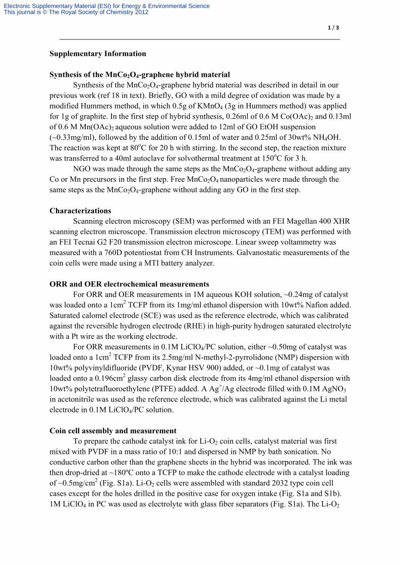
To prepare the cathode catalyst ink for Li-O2 coin cells, catalyst material was first mixed with PVDF in a mass ratio of 10:1 and dispersed in NMP by bath sonication. No conductive carbon other than the graphene sheets in the hybrid was incorporated. The ink was then drop-dried at ~180ºC onto a TCFP to make the cathode electrode with a catalyst loading of ~0.5mg/cm2 (Fig. S1a). Li-O2 cells were assembled with standard 2032 type coin cell cases except for the holes drilled in the positive case for oxygen intake (Fig. S1a and S1b). 1M LiClO4 in PC was used as electrolyte with glass fiber separators (Fig. S1a). The Li-O2
Electronic Supplementary Material (ESI) for Energy & Environmental ScienceThis journal is © The Royal Society of Chemistry 2012
2 / 3
cells were tested in a dry box with desiccants added (Fig. S1c). O2 or air was continuously fed into the box.
Fig. S1 (a) A photo of coin cell cases, separator and cathode electrode for Li-O2 cells. (b) A photo of an assembled Li-O2 cell. (c) A photo of the modified dry box used for measuring Li-O2 cells with oxygen or air flows.
Catalyst on TCFP
Glass fiber separator
(a)
(b)
(c)
Electronic Supplementary Material (ESI) for Energy & Environmental ScienceThis journal is © The Royal Society of Chemistry 2012
3 / 3
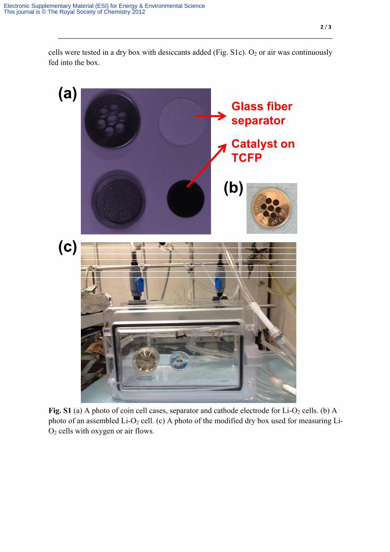
Fig. S2 A MnCo2O4-graphene catalyzed Li-air cell. (a) Charging and discharging voltage profiles of the cell at 100mA/g. (b) Specific discharge capacity of the cell at a current density of 400mA/g. A capacity cut-off of 1000mAh/g was used. (c) Cell voltage upon completion of each discharge (black) and charge (red) segment over the 20 cycles in (b).
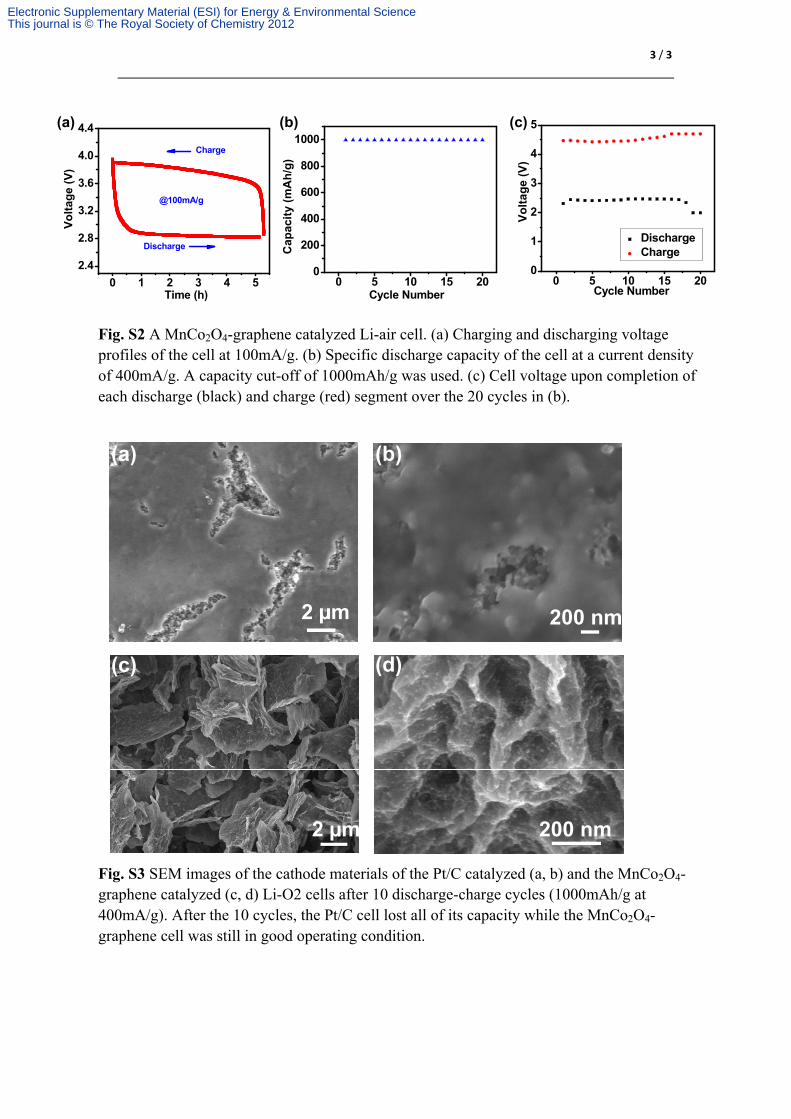
Fig. S3 SEM images of the cathode materials of the Pt/C catalyzed (a, b) and the MnCo2O4-graphene catalyzed (c, d) Li-O2 cells after 10 discharge-charge cycles (1000mAh/g at 400mA/g). After the 10 cycles, the Pt/C cell lost all of its capacity while the MnCo2O4-graphene cell was still in good operating condition.
0 5 10 15 200
200
400
600
800
1000
Cap
acit
y (m
Ah
/g)
Cycle Number0 1 2 3 4 5
2.4
2.8
3.2
3.6
4.0
4.4
@100mA/g
Charge
Vo
ltag
e (V
)
Time (h)
Discharge
(a) (b)
0 5 10 15 200
1
2
3
4
5
Vo
lta
ge
(V)
Cycle Number
Discharge Charge
(c)
2 µm 200 nm
200 nm2 µm
(a)
(d)(c)
(b)
Electronic Supplementary Material (ESI) for Energy & Environmental ScienceThis journal is © The Royal Society of Chemistry 2012