Embed Size (px)
Citation preview

Research ArticleSynthesis of Graphene-Based Nanocomposite andInvestigations of Its Thermal and Electrical Properties
Manoj Kumar Pati,1 Puspalata Pattojoshi,1 and Gouri Sankar Roy2
1Department of Physics, KIIT University, Bhubaneswar, Odisha 751024, India2PG Department of Physics, College of Engineering and Technology, Bhubaneswar, Odisha 751003, India
Correspondence should be addressed to Manoj Kumar Pati; [email protected]
Received 15 April 2016; Revised 21 June 2016; Accepted 22 June 2016
Academic Editor: Simon Joseph Antony
Copyright © 2016 Manoj Kumar Pati et al. This is an open access article distributed under the Creative Commons AttributionLicense, which permits unrestricted use, distribution, and reproduction in any medium, provided the original work is properlycited.
We describe the synthesis of acid functionalized graphene (GE) which is grafted to chitosan (CH) by first reacting the oxidized GEwith thionyl chloride to form acyl-chlorinated GE. This product is subsequently dispersed in chitosan and covalently grafted toform GE-chitosan. GE-chitosan is further grafted onto polymetanitroaniline (PMNA) by free radical polymerization conditionsto yield GE-CH-PMNA. We have characterized the structure of synthesized GE-CH-PMNA composites by X-ray diffraction(XRD), Fourier transform infrared spectroscopy (FTIR), thermogravimetric analysis (TGA), scanning electron microscopy, andconductivitymeasurements. XRDdata suggest the strongly crystalline character of the prepared specimen.Ourmeasurement showsthat the dielectric constants of these nanocomposites are remarkably enhanced due to interfacial polarization effect. This studydemonstrates that functionalized graphene sheets are ideal nanofillers for the development of new polymer composites with highdielectric constant values.
1. Introduction
Graphene is the most basic form of carbon. It is composed ofsp2 bonded carbon atoms arranged in a hexagonal arrange-ment in a 2D plane [1]. The lattice of graphene consists oftwo interleaved triangular shaped carbon sublattices. Thesublattices overlap in such a way that carbon atom fromone sublattice is at the centroid of the other sublattice [2–4].Graphene has been used in many engineering and industrialapplications to create compositematerials with superior qual-ities such as lubricants, functional fluids, and high temper-ature gaskets. In these applications, one-carbon-atom thickgraphene can be a very promising reinforcing agent [5–7] andprovide exceptional electrical and thermal transport proper-ties compared to other nanomaterials such as layered silicatesor CNTs [8–10]. Graphene-based polymer nanocompositesexhibit superior properties of graphene [11]. For example,graphene-based polymer composites show better mechani-cal, thermal, and electrical properties than the neat polymer[12]. It has been shown that the mechanical and electricalproperties of graphene-based polymer composites are much
better in comparison to clay or other carbon filler-basedpolymer composites [13–17].
Due to high electrical conductivity, chemically modifiedgraphene composites have been studied for potential elec-tronic device applications such as photovoltaic solar cells andfield effect transistors [18]. Similarly, graphene compositesincorporating conductive polymers have also been studiedfor energy storage [19]. Besides being used in devices, poly-mer based graphene nanocomposites are also envisioned for awide range of chemical and biochemical sensing applications[20]. Physical and chemical properties of the graphene-based polymer nanocomposite depend on the distributionof graphene layers in the polymer matrix and the interfacialbonding between the graphene layers and polymer matrix.However, pristine graphene does not form homogeneouscomposites, since it is not compatible with organic polymers.On the other hand, graphene oxide (GO) sheets which areheavily oxygenated graphene are compatible with organicpolymers [21–26]. Therefore, GO is widely used as nanofillerfor polymer nanocomposites. Unlike graphene, GO is
Hindawi Publishing CorporationJournal of NanotechnologyVolume 2016, Article ID 5135420, 9 pageshttp://dx.doi.org/10.1155/2016/5135420

2 Journal of Nanotechnology
electrically insulating and therefore cannot be used forsynthesizing conducting nanocomposites.
Chitosan (CH) is a naturally semicrystalline cationicpolysaccharide, which has found widespread applicationsas a biopolymer in tissue engineering and drug deliveryapplications [27]. Chitosan forms composites withGO sheets.The positive value of zeta potential of CH is caused by proto-nated amino groups while the negative zeta potential for GOsuspension is caused by deprotonated carboxyl groups [28–30]. The effect of GO on the properties of CH films has beenstudied by Han et al. [31] by preparing CH/GO nanocom-posites using solution mixing method. Strong interactionsbetween the functional groups of the two components havebeen observed, which led to improvedmechanical strength inbothwet and dry state, storagemodulus, and thermal stabilityfor the CH/GO nanocomposite. Similar mechanical andthermal properties have also been observed in CH/ReducedGO (RGO) nanocomposites by Wang et al. [32]. Tensilestrength of this CH/RGOnanocomposite wasmeasured to behigher than that of pure chitosan, while it also exhibited highelectrical conductivity. Graphene/CH nanocomposites havealso been developed for electrochemical sensor applicationsfor which properties such as high electrical conductivity andelectron transfer rate of graphene are highly suitable [33].In this study, the redox peak current of 4-aminophenol wasfound to be enhanced indicating the electrocatalytic effect ofgraphene.
GO/CH nanocomposite films containing chitosan wererecently prepared via solution mixing (i.e., sonochemicalmethod) for use in electrochemical biosensors [34]. Pres-ence of GO revealed improved thermal stability, increasedglass transition temperature, and storage modulus of theGO/CH nanocomposite film. Cyclic voltammetric experi-ment showed that the GO/CH modified electrode exhibitedhigher electrocatalytic activity than neat CH. The GO/CHcomposite suspension yields a suspension with a zeta poten-tial of ∼51mV due to strong ionic interactions between posi-tively charged CH and negatively charged GO. It is importantto note that this suspension with zeta potential higher than30mV is considered to be stable [35]. Homogeneous GO/CHsuspensions are prepared by addingGO to the solution of chi-tosan [36]. The GO/CH composite film is formed by electro-deposition on the surface of the cathode [37].
In this paper, we discuss the synthesis of a particular typeof graphene-based nanocomposite using CH and polymetan-itroaniline (PMNA) and investigate its physical, chemical,and electrical properties with different compositions. PMNAis a conducting polymer widely used in the fabrication ofelectrodes and sensors. The novelty of our research liesin synthesizing functionalized graphene attached with thenatural polymer chitosan and then cross-linking with PMNAto produce a new type of graphene/conducting polymer com-posite. Chemical modifications of GE-CH-PMNA nanocom-posite are confirmed using a number of material characteri-zation techniques such as X-ray diffraction (XRD), scanningelectron microscope (SEM), and Fourier transform infraredspectroscopy (FTIR). Physical and electrical properties suchas material decomposition, heat capacity, dielectric constant,and conductivity of the GE-CH-PMNA nanocomposite are
determined from thermogravimetric analysis (TGA), differ-ential scanning colorimetry (DSC), and electronic measure-ments. In this research,we have demonstrated that the combi-nation of graphene and the conducting polymer PMNA leadsto a synergistic composite material possessing the propertiesof each of the constituent components. The dielectric con-stant of this composite is increased with the increase in thevolume fraction of functionalized GE (F-GE) and reaches amaximum value of 3200 at 8 vol% of F-GE.
2. Materials and Methods
2.1. Materials. Graphene (GE), chitosan (CH), and PMNAused in our studies were purchased from Sigma-Aldrich.Analytical grade chemical reagents like potassium persulfate(K2S2O8) and hydrochloric, sulfuric, and nitric acid used in
our experiments were obtained from Sigma Chemicals. Fig-ure 1 illustrates the basic reaction scheme used in the synthe-sis of GE-CH-PMNA nanocomposite. In the following sec-tion, we first describe the process used to prepare functional-ized graphene. Next, we describe how we took advantage ofthe existence of some of the free amino groups in chitosanto graft functionalized graphene with chitosan and furtherwith PMNA to produce GE-CH-PMNA nanocomposites.
2.2. Synthesis of Functionalized Graphene. Functionalizedgraphene was synthesized as described in our previous work[38]. Typically, GE was reacted with H
2SO4and HNO
3acids
with 3 : 1 ratio and later sonicated for 30 minutes using anultrasonic sonicator to form carboxylic acid functionalizedGE (GE-COOH). The carboxylic acid group was convertedto formyl chloride by reaction with thionyl chloride for 24 hat 75∘C. This resulted in functionalized GE-COCl as shownby the reaction scheme in Figure 1.The reaction was stopped,and the mixture was cooled before centrifuging and washingto remove excess reactants. The sample was then driedovernight at a temperature of 90∘C and 30 Hg pressure.
2.3. Synthesis of GE-Chitosan. As shown by the reactionscheme in Figure 1, the functionalized GE-COCl (400mg)was further reacted with chitosan (2 g) in 100mL 2% aceticacid at 75∘C for 24 hours while stirring. This resulted in GE-chitosan. For removing the unreacted chitosan, the productwas washed three times with 2% acetic acid after the reactionwas stopped.
2.4. Synthesis of GE-Chitosan Grafted Derivative. GE-chitosan (0.1 g) was again reacted with K
2S2O8(0.02 g) and
PMNA (8mL) in 2% acetic acid solution at 75∘C for 2 h toform the nanocomposite product GE-CH-PMNA. The finalproduct was prepared by centrifuging at 20,000 rpm andwashing the sample twice with water before drying at 90∘C.
3. Results and Discussions
The structural, thermal, and electrical measurements werecarried out on GE-CH-PMNA composite, and the importantand interesting results obtained from the above characteriza-tion techniques are described below sequentially.

Journal of Nanotechnology 3
Graphene (GE) GE-COOH GE-COCL
F-GE-chitosan (CH)F-GE-CH-PMNA
Figure 1: Reaction scheme used in the synthesis of GE-CH-PMNA.
GE
CH
10 80
Inte
nsity
(a.u
.)
20 30 40 50 60 70
2𝜃 (degree)
(a)
10 20 30 40 50 60
2𝜃
Inte
nsity
(cou
nt)
1500
1200
900
600
300
0
Polymetanitroaniline (PMNA)
(b)
5 10 15 20 25 30 35
2𝜃
Inte
nsity
(a.u
.)
8
7
6
5
4
3
2
1
0
(c)
Figure 2: XRD measurements of (a) GE and CH, (b) PMNA, and (c) GE-CH-PMNA composite.
3.1. XRD Measurements. X-ray diffraction (Rigaku, D/Max,2500V, Cu-K𝛼 radiation: 1.54056 A) experiments were car-ried out on graphene, chitosan, and the composite GE-CH-PMNA sample. Wide-angle X-ray diffractograms wererecorded in the range of 0–80∘ (2𝜃) angle keeping the sampleat temperature 30∘C. In Figure 2(a), the XRD pattern of chi-tosan shows broad diffraction peaks at 18∘ and 25∘ which arethe typical fingerprints of semicrystalline chitosan. Grapheneshows a strong and sharp peak at 32∘ indicating a higherordered structure. Figure 2(b) shows the recorded XRDspectrum of PMNAwith diffraction peaks appearing at 12.3∘,
16.9∘, 18.8∘, and 22.6∘. Using these peaks as spectral signatures,we can determine the presence of PMNA and its crystalstate in the composite. Figure 2(c) shows the XRD patternof the composite GE-CH-PMNA producing multiple peakscorresponding to 2𝜃 at 19∘, 21.9∘, 23∘, 27∘, and 34∘ due to thepresence of CH-PMNA along with GE. The XRD pattern ofthe GE-CH-PMNA composite contains all peaks assigned toboth GE and the individual matrix, and it also shows sharpnew peaks formed due to increase in ordering of the polymercomposite. This indicates that the crystalline structure of GEis strongly influenced by the addition of CH-PMNA. The

4 Journal of Nanotechnology
1% GE-CH-PMNA
(a)
2% GE-CH-PMNA
(b)
3% GE-CH-PMNA
(c)
Figure 3: SEM images showing cross sections of GE-CH-PMNA composites with 1 wt%, 2wt%, and 3wt% of CH, respectively.
XRD result also shows that GE has been efficiently exfoliatedwithin the CHmatrix due to the presence of diminished peakat 32∘.
3.2. Characterization Using SEM Image. The surface mor-phology of the GE-CH-PMNA nanocomposite was investi-gated by a scanning electron microscope (SEM, Zeiss). Inorder to investigate the influence of the graphene chemicalfunctionalities on the morphology of graphene-based com-posites, GE and copolymer-modified graphene were blendedwith the polymer matrix. The SEM images in Figure 3 showthe cross sections of composites containing 1 wt%, 2wt%,and 3wt% of CH in GE-CH-PMNA. The images show GE-PMNA is dispersed in the composite due to the formationof agglomerates at length scales of tens of microns. Figures3(b) and 3(c) show a better distribution ofGEparticles homo-geneously covered by the polymer. The copolymer-modifiedgraphene composite can be homogeneously integratedwithinhydrophilicCHmatrix.Thepresence of ionicmoieties such asalkyl amino- and carboxylates in the polymer backbone canresult in enhanced interfacial interactions between the fillerand the matrix.
3.3. FTIR Spectra. The Fourier transform infrared (FTIR)spectra for various samples have been obtained using a
Nicolet 8700 spectrometer, in the range of 500–4,000 cm−1.Figure 4(a) shows the FTIR spectra of neat chitosan andgraphene along with functionalized graphene (F-GE). TheFTIR spectrum of chitosan shows a broad absorption bandbetween 3500 cm−1 and 2500 cm−1, centered at 3200 cm−1,due to O–H stretching vibration, N–H extension vibra-tion, and the intermolecular H-bonds of the polysaccharidemoieties. A spectral band at 2790 cm−1 is observed whichcorresponds to the axial stretching of C–H bonds. A peakat 1673 cm−1 is observed which corresponds to the axialstretching of C=O bonds of the acetamide group. Anotherspectral band at 1559 cm−1 is observed which is related to theangular deformation of N–H bonds of the amino group. Aband at 1372 cm−1 due to symmetrical angular deformation ofCH3and the amide III band at 1322 cm−1 are also observed.
Spectral band corresponding to the polysaccharide skeleton,including vibrations of the glycoside bonds, and C–O and C–O–C stretching in the range 1156–800 cm−1 are also observed[39, 40] in the FTIR spectrum of chitosan. Similarly, the FTIRpeak of GE in Figure 4(a) shows prominent O–H stretchingvibrations observed at 3453 cm−1. Stretching vibrations fromC=O are observed at 1735 cm−1 whereas the C–O stretchingvibrations at 1660 cm−1 are also observed. In case of F-GE, multiple FTIR peaks at 3447 cm−1 (–OH stretching),

Journal of Nanotechnology 5
Tran
smitt
ance
(%)
05001000150020002500300035004000
102030405060708090
100
3856 3747
3456 1743
2978
2856
28512930
3453
37373866
3745
3481 29452864 1652
1590 13761162 1078
932
16231478 1176
1104125416201734
1110
767 F-GE
GE
CH
Wavenumber (cm−1)
(a)
36563205
2723
2267
1678
34023751
34862883
2971
1759
1664
1295
1232
1112
1067751
802752
GE-CH-PMNA
PMNA
50010001500200025003000350040000
20
40
60
80
100
120
Wavenumber (cm−1)
(b)
Figure 4: FTIR spectra obtained for (a) CH, GE, and functionalized GE (F-GE) and compared with those for (b) PMNA and GE-CH-PMNAcomposite.
2894 cm−1 (–O–H stretch), 1692 cm−1 (C=C ring stretch-ing), 1385 cm−1 [𝜐(C=C), 𝛿(O–H), 𝜐(C–O)], 1110 cm−1 (C–Ostretch), 891 cm−1 (alkyl halide stretch), and 651 cm−1 (C–Clstretch) are observed which are formed by the functional car-boxyl group.
Figure 4(b) shows the FTIR spectra of PMNA usedin cross-linking and the GE-CH-PMNA nanocomposite.The FTIR spectrum of PMNA shows the vibration modesof benzene and quinoid rings appearing at 1513 cm−1. Thepresence of bands in FTIR spectrum in the region extendingfrom 741 cm−1 confirms that there are 1,2,4-tri-substitutedrings in the polymeric backbones. The FTIR spectrum ofthe electrodeposited GE-CH-PMNA film showed bands at1585 and 1410 cm−1, which may be assigned to typical PMNAring vibrations. The spectral band at 1245 cm−1 correspondsto –C–H bond in-plane vibrations. The peak at 1175 cm−1 isassigned to the N–C stretching vibration, and the band at1098 cm−1 verified the presence of polymerized polymetani-troaniline.The FTIR peak observed at 3434 cm−1 is attributedto hydroxyl stretching vibrations of –C–OH in graphene.Table 1 provides the dip positions and their origin in the FTIRspectra shown in Figure 4(b) for PMNAand the preparedGE-CH-PMNA nanocomposite sample.
3.4. TGAMeasurements. Thermogravimetric analysis (TGA)of the composite material has been carried out using TGAinstrument TGA/SDTA851 at 20𝜇C/min heating rate undernitrogen. The thermal stability of the composite material hasbeen assessed by TGA while keeping the material in an inertatmosphere. Figure 5(a) shows the onset temperature for pureCH degradation at about 350∘C, which is attributed to themain-chain pyrolysis. At about 450∘C, the total amount ofpolymer seemed to be pyrolyzed. It is found from Figure 5(a)that the samples containing 1 wt% GE and 1% GE-CHexhibited similar thermal stability. This can be explainedby the following. The initial weight loss due to evaporationof solvent occurs at low temperature which is common toboth pure GE and GE-CH. With the increase of temperature
Table 1: FTIR dip positions and their origin for PMNAandGE-CH-PMNA.
Chemical Peak position (cm−1) Assignment
PMNA
3656 OH stretching3402 OH stretching3205 –O–H stretch2723 C–H medium2267 Alkynes stretch1678 Alkenes stretch1513 Benzene and quinoid ring1295 Amine stretch1112 C–N medium802 Alkyl halide stretch741 C–Cl stretch
GE-CH-PMNA
3751 –OH stretching3434 –OH stretching2971 –O–H stretch2883 –CH
2
1775C=O stretching arisingfrom carbonyl andcarboxylic groups
1664 C=N medium1585 PMNA ring vibration1410 PMNA ring vibration1245 C–O strong1175 N–C stretching1098 C–O stretch751 =C–H bending
beyond 300∘C, typically weight loss due to the change ofmode (or phase) occurs in the sample. The identical thermalbehavior of the pure GE and GE-CH probably indicates thatCH remains inert in case of GE-CH composite. Figure 5(b)

6 Journal of Nanotechnology
0
20
40
60
80
100
120
100 200 300 400 500 600
Wei
ght (
%)
CH1% wt GE
1% GE-CH
Temperature (∘C)
(a)
0
20
40
60
80
100
120
100 200 300 400 500 600
Wei
ght (
%)
1% GE-CH-PMNA2% GE-CH-PMNA
3% GE-CH-PMNA
Temperature (∘C)
(b)
Figure 5: TGA profiles for (a) CH, 1 wt% GE, and 1% GE-CH and (b) 1, 2, and 3wt% GE-CH-PMNA.
0 40 80 120 160 200 240 280
Hea
t flow
(W/g
)
CH1% GE-CH-PMNA
3% GE-CH-PMNA2% GE-CH-PMNA
Temperature (∘C)
1
0
−1
−2
−3
−4
−5
−6
−7
−8
−9
Figure 6: DSC thermograms of CH, 1% GE-CH-PMNA, 2% GE-CH-PMNA, and 3% GE-CH-PMNA.
shows TGA profiles for 1, 2, and 3wt% GE-based composites.These materials also exhibit similar thermal stability exceptthe fact that 1 wt% GE-based composite shows higher weightloss compared to others at the same temperature. The ini-tial degradation observed between 200 and 280∘C in thesecomposites is attributed to the elimination of the oxygen-containing groups in the oxidized graphene nanoplatelets.The second degradation observed between 350 and 480∘Chappens due to the degradation of the polymer itself [34].These results also suggest that there is a strong interactionbetween CH and GE nanoplatelets at the interface, and themobility of the polymer chains near the interface is decreasedbecause of this interaction.
3.5. DSC Measurements. Differential scanning calorimetry(DSC)measurements have been carried out to confirm stronginteraction of the prepared graphene nanostructures withthe polymer matrix. DSC thermograms shown in Figure 6
are obtained for CH, 1% GE-CH-PMNA, and GE-CH-PMNA composites with 2 and 3wt%. From these heat scans,one can see the integrated area of the melting transition(Δ𝐻𝑚) of the samples, containing copolymer-modified GEcomposite. In this GE weight fraction, it is estimated thatthe relative crystallinity of the copolymer-modified GE/CHsample has been increased by about 5%, compared to theone of neat matrix. This crystallinity increase indicates thatthe polymer chains were indeed immobilized by hydrophobicand/or hydrogen bonding interactions with the GE. Overall,the order of relative crystallinity in our samples (at 1 wt%graphene loading) for copolymer-modified GE is found to begreater than the neatmatrix.The fact that the sample of 3%wtGE exhibited a 15% decrease in crystallinity compared to neatCH could be attributed to the inhomogeneous dispersion ofGE aggregates into thematrix.Themelting endothermic peakof neat matrix (at about 230∘C) was slightly decreased in thecomposites. This could be attributed to the relatively smallercrystal size of CH due to the intercalation of GE [41].
3.6. Dielectric and Conductivity Properties of GE-CH-PMNA.Figure 7(a) shows the electrical conductivity and the dielec-tric constants of the GE-CH-PMNA composites as a functionof the volume fraction of the functionalized GE (F-GE)measured at room temperature and 1 kHz. The electricalconductivity of the composite is increased by more than fiveorders of magnitude with increase in F-GE concentration.The conductivity for the composite material can be analyzedby the following scaling equation [41, 42]:
𝜎eff = 𝜎𝑖 (𝑝GE − 𝑝𝑐)𝑡
, (1)
where 𝜎𝑖is related to bulk electrical conductivity of GE,𝑝GE is
the weight fraction of F-GE, 𝑝𝑐is the percolation threshold,
and 𝑡 is the critical exponent. The conductivity of GE-CH-PMNA composite increases near the percolation threshold𝑝
𝑐which is found to be 3.5 vol%. Beyond the threshold, it
exhibits a typical insulator-conductor transition. Conduc-tivity of GE-CH-PMNA composites below the percolation
Journal of Nanotechnology 7
0 0.02 0.04 0.06 0.08 0.1 0.12
Con
duct
ivity
(S/c
m)
Volume fraction of GE
−3
−4
−5
−6
−7
−8
−9
(a)
0
500
1000
1500
2000
2500
3000
3500
4000
0 0.02 0.04 0.06 0.08 0.1 0.12 0.14
Die
lect
rical
cons
tant
Volume fraction of F-GE(b)
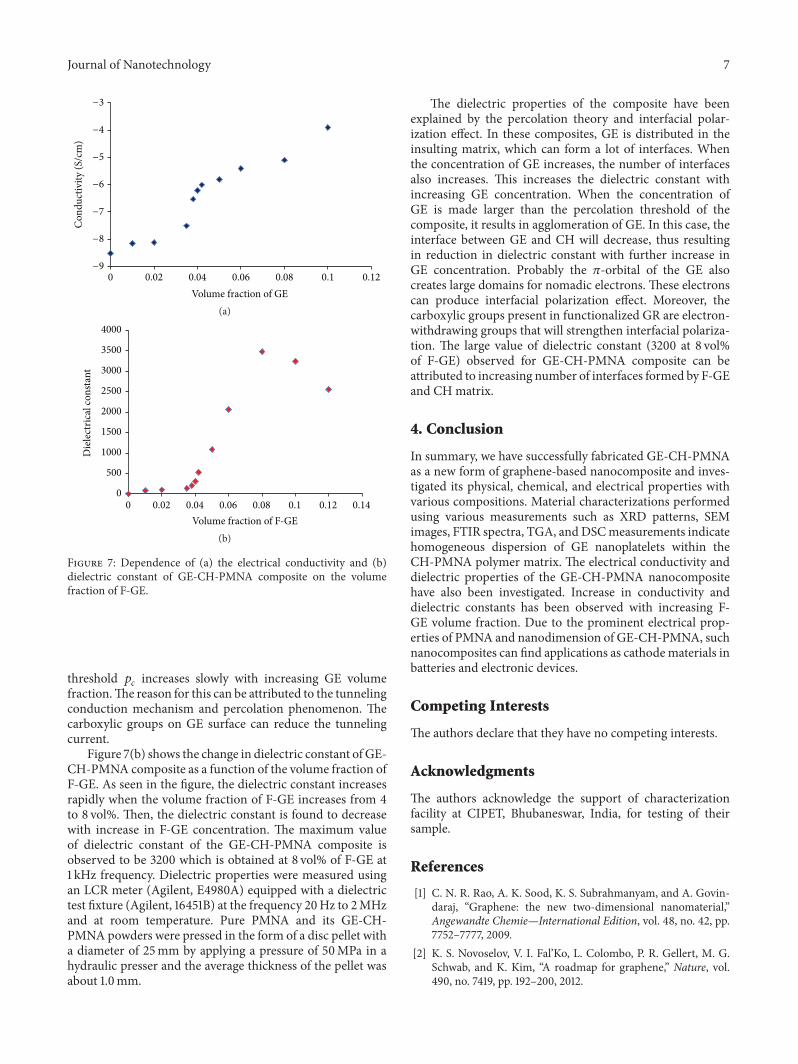
Figure 7: Dependence of (a) the electrical conductivity and (b)dielectric constant of GE-CH-PMNA composite on the volumefraction of F-GE.
threshold 𝑝𝑐increases slowly with increasing GE volume
fraction.The reason for this can be attributed to the tunnelingconduction mechanism and percolation phenomenon. Thecarboxylic groups on GE surface can reduce the tunnelingcurrent.
Figure 7(b) shows the change in dielectric constant of GE-CH-PMNA composite as a function of the volume fraction ofF-GE. As seen in the figure, the dielectric constant increasesrapidly when the volume fraction of F-GE increases from 4to 8 vol%. Then, the dielectric constant is found to decreasewith increase in F-GE concentration. The maximum valueof dielectric constant of the GE-CH-PMNA composite isobserved to be 3200 which is obtained at 8 vol% of F-GE at1 kHz frequency. Dielectric properties were measured usingan LCR meter (Agilent, E4980A) equipped with a dielectrictest fixture (Agilent, 16451B) at the frequency 20Hz to 2MHzand at room temperature. Pure PMNA and its GE-CH-PMNA powders were pressed in the form of a disc pellet witha diameter of 25mm by applying a pressure of 50MPa in ahydraulic presser and the average thickness of the pellet wasabout 1.0mm.
The dielectric properties of the composite have beenexplained by the percolation theory and interfacial polar-ization effect. In these composites, GE is distributed in theinsulting matrix, which can form a lot of interfaces. Whenthe concentration of GE increases, the number of interfacesalso increases. This increases the dielectric constant withincreasing GE concentration. When the concentration ofGE is made larger than the percolation threshold of thecomposite, it results in agglomeration of GE. In this case, theinterface between GE and CH will decrease, thus resultingin reduction in dielectric constant with further increase inGE concentration. Probably the 𝜋-orbital of the GE alsocreates large domains for nomadic electrons. These electronscan produce interfacial polarization effect. Moreover, thecarboxylic groups present in functionalized GR are electron-withdrawing groups that will strengthen interfacial polariza-tion. The large value of dielectric constant (3200 at 8 vol%of F-GE) observed for GE-CH-PMNA composite can beattributed to increasing number of interfaces formed by F-GEand CH matrix.
4. Conclusion
In summary, we have successfully fabricated GE-CH-PMNAas a new form of graphene-based nanocomposite and inves-tigated its physical, chemical, and electrical properties withvarious compositions. Material characterizations performedusing various measurements such as XRD patterns, SEMimages, FTIR spectra, TGA, andDSCmeasurements indicatehomogeneous dispersion of GE nanoplatelets within theCH-PMNA polymer matrix. The electrical conductivity anddielectric properties of the GE-CH-PMNA nanocompositehave also been investigated. Increase in conductivity anddielectric constants has been observed with increasing F-GE volume fraction. Due to the prominent electrical prop-erties of PMNA and nanodimension of GE-CH-PMNA, suchnanocomposites can find applications as cathodematerials inbatteries and electronic devices.
Competing Interests
The authors declare that they have no competing interests.
Acknowledgments
The authors acknowledge the support of characterizationfacility at CIPET, Bhubaneswar, India, for testing of theirsample.
References
[1] C. N. R. Rao, A. K. Sood, K. S. Subrahmanyam, and A. Govin-daraj, “Graphene: the new two-dimensional nanomaterial,”Angewandte Chemie—International Edition, vol. 48, no. 42, pp.7752–7777, 2009.
[2] K. S. Novoselov, V. I. Fal’Ko, L. Colombo, P. R. Gellert, M. G.Schwab, and K. Kim, “A roadmap for graphene,” Nature, vol.490, no. 7419, pp. 192–200, 2012.

8 Journal of Nanotechnology
[3] V. Georgakilas, M. Otyepka, A. B. Bourlinos et al., “Function-alization of graphene: covalent and non-covalent approaches,derivatives and applications,” Chemical Reviews, vol. 112, no. 11,pp. 6156–6214, 2012.
[4] X. Huang, X. Qi, F. Boey, and H. Zhang, “Graphene-basedcomposites,” Chemical Society Reviews, vol. 41, no. 2, pp. 666–686, 2012.
[5] V. Singh, D. Joung, L. Zhai, S. Das, S. I. Khondaker, and S. Seal,“Graphene basedmaterials: past, present and future,” Progress inMaterials Science, vol. 56, no. 8, pp. 1178–1271, 2011.
[6] Y. Shao, J. Wang, H. Wu, J. Liu, I. A. Aksay, and Y. Lin,“Graphene based electrochemical sensors and biosensors: areview,” Electroanalysis, vol. 22, no. 10, pp. 1027–1036, 2010.
[7] Y. Zhu, S. Murali, W. Cai et al., “Graphene and graphene oxide:synthesis, properties, and applications,” Advanced Materials,vol. 22, no. 35, pp. 3906–3924, 2010.
[8] C. Soldano, A. Mahmood, and E. Dujardin, “Production,properties and potential of graphene,”Carbon, vol. 48, no. 8, pp.2127–2150, 2010.
[9] H. S. Chen, T. N. Cong, W. Yang, C. Tan, Y. Li, and Y. Ding,“Progress in electrical energy storage system: a critical review,”Progress in Natural Science, vol. 19, no. 3, pp. 291–312, 2009.
[10] G. A. Snook, P. Kao, and A. S. Best, “Conducting-polymer-based supercapacitor devices and electrodes,” Journal of PowerSources, vol. 196, no. 1, pp. 1–12, 2011.
[11] T. Kuilla, S. Bhadra, D. Yao, N. H. Kim, S. Bose, and J. H.Lee, “Recent advances in graphene based polymer composites,”Progress in Polymer Science, vol. 35, no. 11, pp. 1350–1375, 2010.
[12] S. H. Ryu and A. M. Shanmugharaj, “Influence of long-chainalkylamine-modified graphene oxide on the crystallization,mechanical and electrical properties of isotactic polypropylenenanocomposites,” Chemical Engineering Journal, vol. 244, pp.552–560, 2014.
[13] S. Stankovich, D. A. Dikin, G. H. B. Dommett et al., “Graphene-based composite materials,” Nature, vol. 442, no. 7100, pp. 282–286, 2006.
[14] T. Ramanathan, A. A. Abdala, S. Stankovich et al., “Function-alized graphene sheets for polymer nanocomposites,” NatureNanotechnology, vol. 3, no. 6, pp. 327–331, 2008.
[15] Y. R. Lee, A. V. Raghu, H. M. Jeong, and B. K. Kim, “Proper-ties of waterborne polyurethane/functionalized graphene sheetnanocomposites prepared by an in situ method,”Macromolecu-lar Chemistry and Physics, vol. 210, no. 15, pp. 1247–1254, 2009.
[16] Y. Xu, Y. Wang, J. Liang et al., “A hybrid material of grapheneand poly (3,4-ethyldioxythiophene) with high conductivity,flexibility, and transparency,” Nano Research, vol. 2, no. 4, pp.343–348, 2009.
[17] H. Quan, B.-Q. Zhang, Q. Zhao, R. K. K. Yuen, and R. K. Y. Li,“Facile preparation and thermal degradation studies of graphitenanoplatelets (GNPs) filled thermoplastic polyurethane (TPU)nanocomposites,” Composites Part A: Applied Science and Man-ufacturing, vol. 40, no. 9, pp. 1506–1513, 2009.
[18] G. Eda and M. Chhowalla, “Graphene-based composite thinfilms for electronics,” Nano Letters, vol. 9, no. 2, pp. 814–818,2009.
[19] C.-P. Tien and H. Teng, “Polymer/graphite oxide compositesas high-performance materials for electric double layer capac-itors,” Journal of Power Sources, vol. 195, no. 8, pp. 2414–2418,2010.
[20] Z. Terzopoulou, G. Z. Kyzas, and D. N. Bikiaris, “Recentadvances in nanocomposite materials of graphene derivativeswith polysaccharides,”Materials, vol. 8, no. 2, pp. 652–683, 2015.
[21] H. A. Becerril, J. Mao, Z. Liu, R. M. Stoltenberg, Z. Bao, andY. Chen, “Evaluation of solution-processed reduced grapheneoxide films as transparent conductors,” ACS Nano, vol. 2, no. 3,pp. 463–470, 2008.
[22] D. A. Dikin, S. Stankovich, E. J. Zimney et al., “Preparation andcharacterization of graphene oxide paper,” Nature, vol. 448, no.7152, pp. 457–460, 2007.
[23] J. L. Vickery, A. J. Patil, and S. Mann, “Fabrication of graphene-polymer nanocomposites with higher-order three-dimensionalarchitectures,”AdvancedMaterials, vol. 21, no. 21, pp. 2180–2184,2009.
[24] M. J. McAllister, J.-L. Li, D. H. Adamson et al., “Single sheetfunctionalized graphene by oxidation and thermal expansion ofgraphite,” Chemistry of Materials, vol. 19, no. 18, pp. 4396–4404,2007.
[25] A. B. Bourlinos, D. Gournis, D. Petridis, T. Szabo, A. Szeri, andI. Dekany, “Graphite oxide: chemical reduction to graphite andsurface modification with primary aliphatic amines and aminoacids,” Langmuir, vol. 19, no. 15, pp. 6050–6055, 2003.
[26] S. Stankovich, D. A. Dikin, R. D. Piner et al., “Synthesis ofgraphene-based nanosheets via chemical reduction of exfoli-ated graphite oxide,” Carbon, vol. 45, no. 7, pp. 1558–1565, 2007.
[27] R. Justin and B. Chen, “Characterisation and drug release per-formance of biodegradable chitosan-graphene oxide nanocom-posites,” Carbohydrate Polymers, vol. 103, no. 1, pp. 70–80, 2014.
[28] J. R. Potts, D. R. Dreyer, C. W. Bielawski, and R. S. Ruoff,“Graphene-based polymer nanocomposites,” Polymer, vol. 52,no. 1, pp. 5–25, 2011.
[29] S. J. An, Y. Zhu, S. H. Lee et al., “Thin film fabrication andsimultaneous anodic reduction of deposited graphene oxideplatelets by electrophoretic deposition,” Journal of PhysicalChemistry Letters, vol. 1, no. 8, pp. 1259–1263, 2010.
[30] F. Ordikhani, E. Tamjid, and A. Simchi, “Characterizationand antibacterial performance of electrodeposited chitosan-vancomycin composite coatings for prevention of implant-asso-ciated infections,” Materials Science and Engineering C, vol. 41,pp. 240–248, 2014.
[31] D. Han, L. Yan, W. Chen, and W. Li, “Preparation of chitosan/graphene oxide composite film with enhanced mechanicalstrength in the wet state,” Carbohydrate Polymers, vol. 83, no.2, pp. 653–658, 2011.
[32] X. Wang, H. Bai, Z. Yao, A. Liu, and G. Shi, “Electrically con-ductive and mechanically strong biomimetic chitosan/reducedgraphene oxide composite films,” Journal of Materials Chem-istry, vol. 20, no. 41, pp. 9032–9036, 2010.
[33] H. Yin, Q. Ma, Y. Zhou, S. Ai, and L. Zhu, “Electrochemicalbehavior and voltammetric determination of 4-aminophenolbased on graphene-chitosan composite film modified glassycarbon electrode,” Electrochimica Acta, vol. 55, no. 23, pp. 7102–7108, 2010.
[34] L.He,H.Wang, G. Xia, J. Sun, andR. Song, “Chitosan/grapheneoxide nanocomposite films with enhanced interfacial interac-tion and their electrochemical applications,” Applied SurfaceScience, vol. 314, pp. 510–515, 2014.
[35] M. R. Mohammadi, F. Ordikhani, D. J. Fray, and F.Khomamizadeh, “Template-based growth of titanium dioxidenanorods by a particulate sol-electrophoretic depositionprocess,” Particuology, vol. 9, no. 2, pp. 161–169, 2011.
[36] M. Fang, J. Long, W. Zhao, L. Wang, and G. Chen, “pH-responsive chitosan-mediated graphene dispersions,” Lang-muir, vol. 26, no. 22, pp. 16771–16774, 2010.

Journal of Nanotechnology 9
[37] Y. Wan, Z. Lin, D. Zhang, Y. Wang, and B. Hou, “Impedimetricimmunosensor doped with reduced graphene sheets fabricatedby controllable electrodeposition for the non-labelled detectionof bacteria,” Biosensors and Bioelectronics, vol. 26, no. 5, pp.1959–1964, 2011.
[38] M. K. Pati, P. Pattojoshi, and G. S. Roy, “Fabrication and char-acterization of graphene based nanocomposite for electricalproperties,” Advances in Materials Physics and Chemistry, vol.5, no. 1, pp. 22–30, 2015.
[39] R. Devi, S. Relhan, and C. S. Pundir, “Construction of a chi-tosan/polyaniline/graphene oxide nanoparticles/polypyrrole/Au electrode for amperometric determination of urinary/plasma oxalate,” Sensors and Actuators B: Chemical, vol. 186, pp.17–26, 2013.
[40] X. Li, H. Zhou, W. Wu, S. Wei, Y. Xu, and Y. Kuang,“Studies of heavy metal ion adsorption on Chitosan/Sulfydryl-functionalized graphene oxide composites,” Journal of Colloidand Interface Science, vol. 448, pp. 389–397, 2015.
[41] R. K. Layek, S. Samanta, and A. K. Nandi, “Graphene sulphonicacid/chitosan nano biocomposites with tunablemechanical andconductivity properties,” Polymer, vol. 53, no. 11, pp. 2265–2273,2012.
[42] J. Jagiello, J. Judek, M. Zdrojek, M. Aksienionek, and L.Lipinska, “Production of graphene composite by direct graphiteexfoliation with chitosan,”Materials Chemistry and Physics, vol.148, no. 3, pp. 507–511, 2014.

Submit your manuscripts athttp://www.hindawi.com
ScientificaHindawi Publishing Corporationhttp://www.hindawi.com Volume 2014
CorrosionInternational Journal of
Hindawi Publishing Corporationhttp://www.hindawi.com Volume 2014
Polymer ScienceInternational Journal of
Hindawi Publishing Corporationhttp://www.hindawi.com Volume 2014
Hindawi Publishing Corporationhttp://www.hindawi.com Volume 2014
CeramicsJournal of
Hindawi Publishing Corporationhttp://www.hindawi.com Volume 2014
CompositesJournal of
NanoparticlesJournal of
Hindawi Publishing Corporationhttp://www.hindawi.com Volume 2014
Hindawi Publishing Corporationhttp://www.hindawi.com Volume 2014
International Journal of
Biomaterials
Hindawi Publishing Corporationhttp://www.hindawi.com Volume 2014
NanoscienceJournal of
TextilesHindawi Publishing Corporation http://www.hindawi.com Volume 2014
Journal of
NanotechnologyHindawi Publishing Corporationhttp://www.hindawi.com Volume 2014
Journal of
CrystallographyJournal of
Hindawi Publishing Corporationhttp://www.hindawi.com Volume 2014
The Scientific World JournalHindawi Publishing Corporation http://www.hindawi.com Volume 2014
Hindawi Publishing Corporationhttp://www.hindawi.com Volume 2014
CoatingsJournal of
Advances in
Materials Science and EngineeringHindawi Publishing Corporationhttp://www.hindawi.com Volume 2014
Smart Materials Research
Hindawi Publishing Corporationhttp://www.hindawi.com Volume 2014
Hindawi Publishing Corporationhttp://www.hindawi.com Volume 2014
MetallurgyJournal of
Hindawi Publishing Corporationhttp://www.hindawi.com Volume 2014
BioMed Research International
MaterialsJournal of
Hindawi Publishing Corporationhttp://www.hindawi.com Volume 2014
Nano
materials
Hindawi Publishing Corporationhttp://www.hindawi.com Volume 2014
Journal ofNanomaterials