Embed Size (px)
Citation preview
©2006 Superior Walls of America, Ltd. Page 1
Introduction
At Superior Walls we believe that our products and the structures they support need to last for generations. In order for that to happen you must give thoughtful consideration to the details of your foundation. We have written this Builder Guideline Booklet to assist you in successfully using Superior Walls on your project. Proper site preparation and framing connection details are of particular importance. You will note that we have provided excerpts from the 2003 International Residential Code for One- and Two- Family Dwellings® referred to as the “IRC” as published by the International Code Council®. These excerpts are included to aid in your understanding of the details or application being discussed in the various sections of the book. Please be aware that your municipality may have other requirements beyond those in the model code. For additional information or for help with site-specific conditions and details, please consult your design professional or contact your local Superior Walls representative.
All rights reserved. This 2006 Builder Guideline Booklet™ is copyrighted work owned by Superior Walls of America, Ltd. This Builder Guideline Booklet can be downloaded from the Superior Walls of America, Ltd. website, printed, copied and used in conjunction with the erection and deployment of the products licensed from Superior Walls of America, Ltd. This Builder Guideline Booklet, however, may not be used in any manner not in conjunction with the erection or deployment of the products licensed by Superior Walls of America, Ltd., or amended, modified, changed, or altered in any manner without the specific advance written permission from the copyright owner. For information relating to the use of this Builder Guideline Booklet, please contact: Technical Services, Superior Walls of America, Ltd., 937 East Earl Road, New Holland, PA 17557 [Phone (717) 351-9255].
Safety First
Superior Walls of America urges you to maintain a safe working environment. The protection of the health and safety of everyone on your jobsite needs to be your primary concern.
Construction work can be particularly hazardous and involve many potential areas of concern. Personal protective equipment and other precautions are essential for a safe construction work environment.
We encourage you to:
• Work to prevent accidents and injuries • Increase safety awareness • Understand and obey requirements of environmental and occupational health and safety laws
and regulations • Establish safety responsibilities for your employees

©2006 Superior Walls of America, Ltd. Page 2
Table of Contents
Building / Owner Responsibilities 3 How the Crushed Stone Footing Works 4 Site Preparation 5-11 Soils Verification 5 Required Crushed Stone Depth 6 Excavation 7-8 Drain System / Sump Pump 9 Crushed Stone Footing 10 Cold Weather Practice 10 Corner Pin and Benchmark Placement 11 Road Accessibility / Overhead Obstructions 11 Crane Accessibility 11 Special Excavation Issues 12-18 Intersecting Walls (Overdig Procedures) 12-13 Trenching 14 Daylight Basement (Frost Areas) 15-17 Daylight Basement (Non-Frost Areas) 18 Procedure to Pour Concrete Floor 19-20 Typical Floor Pour 19 Raised Floor Pour 20 Crawl Space Procedures 21-22 Crawl Space with Wood Bracing 21 Crawl Space without Wood Bracing 22 Porches, Garages and Other Inside Fill Conditions 23-24 Garage Wall 24 Framing Connection at the Top of the Wall 25-34 Typical Floor Connection with Joists Perpendicular to Foundation Wall 26-27 Fastening Schedule 28 Typical Floor Connection with Joists Parallel to Foundation Wall 28-29 “I” Joist Blocking Detail and Plywood Fabricated Blocking 30 Floor Truss Connection – Top Chord Bearing 31 Floor Truss Connection – Bottom Chord Bearing 32 Modular Connection 33 Typical Roof Truss Connection 34 Shear Walls 35 Stairwell Header 36 Backfilling 37 Window Installation Details 38-40 Door Installation Details 41-42 Garage Door Installation Details 43-44 Point Loading 45 Beam Pockets 45 Precast Column Pads 46 Support Ledges 47 Interior Finishing 48 Homeowner Guide Appendix A Checklists Appendix B-F Suggestion for Improvement Appendix G

©2006 Superior Walls of America, Ltd. Page 3
Builder / Owner Responsibilities The builder / owner is responsible for the following items:
• Building Permits and Inspections • Soils Verification Page 5, 6 • Excavation Page 7 • Placement of Drain Pipe and Sump Pit Page 9 • Installation of Filter Membrane Page 8, 9 • Cold Weather Practice Page 10 • Placement of Crushed Stone Footing Page 10 • Locating Building Corner Pins and Establishing Grade Page 11 • Site Accessibility for Trucks and Crane Page 11 • Installation of Sill Plate and Framing Attachments Page 25 • Backfilling After Concrete Floor has been Poured and Page 37
Floor Framing has been Completed In order for your Superior Walls supplier to install a product that fully meets the design and performance requirements of your project, you must provide the following information:
• Soil type or bearing capacity • All building floor plans and elevations • Design load per linear foot on the foundation • Beam and column locations, sizes and point loads • Additional point loads and locations, if any • Window and door locations and rough opening sizes • Egress Considerations • Locations and sizes of support ledges (Brickledge, slab supports, etc.) • Interior stairway locations and opening sizes • Inside fill conditions (As with garage, porch or crawlspace frost walls) • Exterior basement entry system specifications • Chimney details • Backfill conditions (rough grading plans) • Top-of-wall benchmark reference / Finished grade elevation

©2006 Superior Walls of America, Ltd. Page 4
How the Crushed Stone Footing Works
The physics of the crushed stone footing are simple:
1. The purpose of any wall footing is to distribute the wall’s load over a sufficiently large area of soil so that the weight-bearing capacity of the soil is not exceeded.
2. The load of the building is carried by the Superior Wall and is transferred to the crushed stone. 3. The load distribution path through the crushed stone is at an angle approximately 60 degrees
from the horizontal. 4. As the depth of the crushed stone layer increases, the effective bearing width on the underlying
soil also increases (see drawing below). 5. The tables in this booklet identify the required depth of the crushed stone footing for various wall
loads and soil bearing capacities.
Virgin Soil EffectiveBearing Width
Crushed Stone Footing Depth
Load
Load Distribution Path(Shaded Area)
10 1/4"
30°
60°
Crushed Stone Footing Depth (inches)
Effective Bearing Width (inches)
4 14 ⅞ 6 17 3/16 8 19 ½
10 21 13/16 12 24 ⅛ 14 26 7/16 16 28 ¾
See Page 10 for applicable 2003 IRC Code References.

©2006 Superior Walls of America, Ltd. Page 5
Site Preparation Soils Verification 1. Determine your soil type from Table 1 on this page and stone depth requirements from Table 2 on
page 6. For assistance identifying your soil type consult with: • Building Department • County Agricultural Extension Service • County Conservation District Officer • Soils Technician / Engineer • Excavator
2. Determine allowable foundation pressure and drainage characteristics (see Table 1). This will affect the required depth of the crushed stone / gravel footing.
3. Establish combined footing load per linear foot. (Consider dead load, live load, snow and wind load.) Acquire loading from building designer or engineer.
4. Determine required depth of crushed stone / gravel footing. (From Table 2. Remember to allow for this depth when determining excavation depth.)
Table 1
Properties of Soils Classified According to the Unified Soil Classification System Table reference: 2003 IRC Table R405.1
Soil Group Unified Soil Classification
System
Soil Description Drainage Characteristics
(a)
Frost Heave Potential
Volume Change Potential
Expansion (b)
Allowable Foundation Pressure
(PSF) (d)
GW Well graded gravel, gravel-sand mixtures, little or no fines
Good Low Low 3000
GP Poorly graded gravels or gravel sand mixtures, little or no fines
Good Low Low 3000
SW Well-graded sands, gravelly sands, little or no fines
Good Low Low 2000
SP Poorly graded sands or gravelly sands, little or no fines
Good Low Low 2000
GM Silty gravels, gravel-sand-silt mixtures Good Medium Low 2000
Group I Excellent
SM Silty sand, sand-silt mixtures Good Medium Low 2000 GC Clayey gravels, gravel-sand-clay mixtures Medium Medium Low 2000 SC Clayey sands, sand-clay mixture Medium Medium Low 2000 ML Inorganic silts and very fine sands, rock flour,
silty or clayey fine sands or clayey silts with slight plasticity
Medium High Low 1500(c)
Group II Fair to Good
CL Inorganic clays of low to medium plasticity, gravelly clays, sandy clays, silty clays, lean clays
Medium Medium Medium to Low
1500(c)
CH Inorganic clays of high plasticity, fat clays Poor Medium High 1500(c) Group III Poor MH Inorganic silts, micaceous or diatomaceous
fine sandy or silty soils, elastic silts Poor High High 1500(c)
OL Organic silts and organic silty clays of low plasticity
Poor Medium Medium By Test
OH Organic clays of medium to high plasticity, organic silts.
Unsatisfactory Medium High By Test
Group IV Unsatisfactory
PT Peat and other highly organic soils Unsatisfactory Medium High By Test (a) The percolation rate for good drainage is over 4 inches per hour, medium drainage is 2 inches to 4 inches per hour, and poor is less than 2 inches per hour. (b) Soils with a low potential expansion typically have a plasticity index (PI) of 0 to 15, soils with a medium potential expansion have a PI of 10 to 35 and soils with a high potential
expansion have a PI greater than 20 (c) Where the building official determines that in-place soils with an allowable bearing capacity of less than 1,500 psf are likely to be present at the site, the allowable bearing capacity
shall be determined by a soils investigation. 2003 IRC Table R401.4.1. (d) Allowable foundation pressure data from 2003 IRC Table 401.4.1.

©2006 Superior Walls of America, Ltd. Page 6
Table 2 Minimum Depth of Crushed Stone Footing (Inches)
(a) Stone must be vibrated in a maximum of 8” lifts. Typical Crushed Stone Footing Details
Clean Crushed Stone(By Others)
*STONE DEPTH ACCORDINGTO TABLE ABOVE
BackfillArea
Locate Auxiliary Drain PipeAccording to Table 3
Concrete Floor(By Others)
Virgin Soil
Alternate Auxiliary Drain Pipe Position(If Permitted By Building Code)
Filter Membrane(By Others)
Auxiliary Drain Pipe toSump or Daylight
Vapor Retarder(May be Required By Code)
Frost Line
See Note Referring to Auxiliary Drain on Page 9
Figure 1
Soil Type & Load Bearing Capacity (PSF) 1500 2000 3000 4000 Construction Type
(Assumed Wall Loading) MH, CH, CL, ML
SC, GC, SM, GM, SP, SW
GP, GW
Conventional light-frame construction 1 – Story (1100 pounds per linear foot) 4” 4” 4” 4” 2 – Story (1800 pounds per linear foot ) 4” 4” 4” 4” 3 – Story (2900 pounds per linear foot ) 12” (a) 6” 4” 4” Masonry veneer over light-frame construction 1 – Story (1500 pounds per linear foot ) 4” 4” 4” 4” 2 – Story (2700 pounds per linear foot ) 10” (a) 6” 4” 4” 3 – Story (4000 pounds per linear foot ) 20” (a) 12” (a) 6” 4”

©2006 Superior Walls of America, Ltd. Page 7
Table 3 Auxiliary Drain Pipe Minimum Locating Distance
Stone Depth Suggested Distance From Superior Wall
Minimum Distance From Superior Wall
4” 12” 3” 6” 12” 4” 8” 12” 5”
10” 12” 6” 12” 12” 7” 14” 12” 9” 16” 14” 10” 20” 16” 12”
Excavation Excavate a typical basement.
• Be sure to confirm that you are working from the approved drawing prior to digging.
• See Figure 2 on page 8 • Allow a 2’-0” overdig at base of
excavation. • Ensure compliance with OSHA
regulations. • Slope grade a minimum of 6” fall within
the first 10’-0” to divert ground water from the foundation area.
• Remember to dig for sump pit.
R401.3 Drainage. Surface drainage shall be diverted to a storm sewer conveyance or other approved point of collection so as to not create a hazard. Lots shall be graded so as to drain surface water away from foundation walls. The grade away from foundation walls shall fall a minimum of 6 inches (152 mm) within the first 10 feet (3048 mm). Exception: Where lot lines, walls, slopes or other physical barriers prohibit 6 inches (152 mm) of fall within 10 feet (3048 mm), drains or swales shall be provided to ensure drainage away from structure.
R404.1.6 Height above finished grade. Concrete and masonry
foundation walls shall extend above the finished grade adjacent to the foundation at all points a minimum of 4 inches (102 mm) where masonry veneer is used and a minimum of 6 inches (152 mm) elsewhere.
Code Reference: 2003 IRC Section R401.3
Code Reference: 2003 IRC Section R404.1.6
©2006 Superior Walls of America, Ltd. Page 8
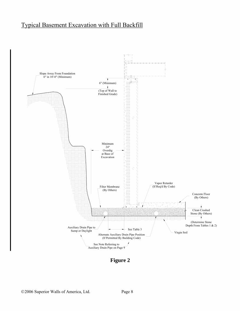
Typical Basement Excavation with Full Backfill
Figure 2
Minimum24"
Overdigat Base ofExcavation
6" (Minimum)
(Top of Wall toFinished Grade)
Concrete Floor(By Others)
Clean CrushedStone (By Others)
(Determine StoneDepth From Tables 1 & 2)
See Table 3Auxiliary Drain Pipe to
Sump or Daylight
Slope Away From Foundation6" in 10'-0" (Minimum)
Virgin SoilAlternate Auxiliary Drain Pipe Position
(If Permitted By Building Code)
Vapor Retarder(If Req'd By Code)Filter Membrane
(By Others)
See Note Referring toAuxiliary Drain Pipe on Page 9

©2006 Superior Walls of America, Ltd. Page 9
Drain System / Sump Pit Install auxiliary drain pipe.
• Use 4” perforated pipe, see Figure 1 on page 6. • Locate pipe according to Table 3 on page 7. • Direct pipe to sump or daylight drain.
a) Sump Pump, supplied by others, must be checked regularly to ensure proper working order.
b) If a daylight drain is used, install a trap to prevent the backflow of moist air into the stone footing area, which will reduce the likelihood of excessive interior humidity. (See illustration below)
• Install filter membrane prior to backfilling. Install Sump Pit
• For large foundations and in areas where you expect a high water table, you should consider using a second sump pit. (or a second outlet to daylight)
R405.1 Concrete or masonry foundations. Drains shall be provided around all concrete or masonry foundations that retain earth and enclose habitable or usable spaces located below grade. Drainage tiles, gravel or crushed stone drains, perforated pipe or other approved systems or materials shall be installed at or below the area to be protected and shall discharge by gravity or mechanical means into an approved drainage system. Gravel or crushed stone drains shall extend at least 1 foot (305 mm) beyond the outside edge of the footing and 6 inches (153 mm) above the top of the footing and be covered with an approved filter membrane material. The top of open joints of drain tiles shall be protected with strips of building paper, and the drainage tiles or perforated pipe shall be placed on a minimum of 2 inches (51 mm) of washed gravel or crushed rock at least one sieve size larger than the tile joint opening or perforation and covered with not less than 6 inches (153 mm) of the same material. Exception: A drainage system is not required when the foundation is installed on well-drained ground or sand-gravel mixture soils according to the Unified Soil Classification System, Group I Soils, as detailed in Table R405.1. Flow Direction
Code Reference: 2003 IRC Section R405.1
Note: Section R405.1 requires a drain around concrete foundations. It notes that gravel or crushed stone drains are permitted (see reference at right). The Superior Walls system utilizes the crushed stone footing as part of the code identified drain and also requires an auxiliary drainage pipe for redundancy. This auxiliary drain pipe should be permitted either inside or outside the wall. Consult your local code official for clarification.
Superior Walls does not permit the utilization of this exception.
Example of a Backflow Trap

©2006 Superior Walls of America, Ltd. Page 10
Crushed Stone Footings Place the crushed stone footing.
• Depth of stone was determined on page 5 using Table 2 on page 6.
• Use clean crushed stone, washed gravel or coarse sand. • Superior Walls recommends clean crushed 1/2”
AASHTO #8 or smaller. • If crushed stone footing is deeper than 8”, place in 8” lifts
and consolidate each lift with a plate vibrator. • Evenly grade the stone to +/- 1 inch of level. • Be sure to have enough material on hand for use in final
grading by the wall installation crew. • See Figure 1 on page 6.
R401.2 Requirements. Foundation construction shall be capable of accommodating all loads according to Section R301 and of transmitting the resulting loads to the supporting soil. Fill soils that support footings and foundations shall be designed, installed and tested in accordance with accepted engineering practice. Gravel fill used as footings for wood and precast concrete foundations shall comply with Section R403.
R402.3 Precast concrete. Approved precast concrete foundations shall be designed and installed in accordance with the provisions of this code and the manufacturer’s installation instructions.
R403.2 Footings for wood foundations. Footings for wood foundations shall be in accordance with figures R403.1 (2) and R403.1 (3). Gravel shall be washed and well graded. The maximum size stone shall not exceed 3/4 inch (19.1 mm). Gravel shall be free from organic, clayey or silty soils. Sand shall be coarse, not smaller than 1/16 inch (1.6 mm) grains and shall be free from organic, clayey or silty soils. Crushed stone shall have a maximum size of 1/2 inch (12.7mm).
Cold Weather Practice
• Do not excavate the site too far in advance of the scheduled set date. Do not place footing on frozen soil. • After the site has been excavated, insulate the area where walls are to be set and protect this area with a
waterproof covering. • Mixing calcium chloride into the stone footing and then covering it will help prevent frost infiltration. (Do not
forget to treat the “extra” stone pile – you may need it to fill-in low spaces in footing.) • Note that 6 inches of straw has approximately the same “R” value as 3 ½” of fiberglass insulation (see chart
below).
Insulating Values of Common Building Insulation Materials Insulation Material Approximate “R” Values
1” of Straw 2.0 ½” of Plywood 0.6 1” of Fiberglass Batt 3.3 1” of Extruded Polystyrene 5.0 Insulated Blankets or Tarps Per Blanket Manufacturer
These recommendations are compiled from a variety of industry sources.
Code Reference: 2003 IRC Section R403.2
Code Reference: 2003 IRC Section R401.2
Code Reference: 2003 IRC Section R402.3
Note: Section R403.2 “Footings for Wood Foundations” applies to precast concrete foundation walls based on the reference in Section 401.2 (see reference at right above).
©2006 Superior Walls of America, Ltd. Page 11
Corner Pin and Benchmark Placement • Establish a benchmark to identify your required top-of-
wall elevation. (Clearly communicate the elevation requirements to your Superior Walls supplier.)
• Set pins that define the building corners. • Pins should represent the exterior face of the Superior
Walls foundation. • Check with your Superior Walls supplier or sales
representative for specific requirements. Road Accessibility / Overhead Obstructions
• The driveway must be wide enough to allow for trailer and crane access.
• The driveway surface and any culverts or bridges must be able to accommodate the weight of the vehicles.
• 9’-0” and 10’-0” walls are delivered on a drop deck trailer and have limited ground clearance.
• The Builder / Homeowner is responsible for any additional equipment or costs necessary to provide access to work area. Consult with your Superior Walls supplier or sales representative for specific details for your jobsite.
• Verify that trees, wires and other overhead obstructions do not block site access.
Crane Accessibility
• Access to the foundation area should be prepared so the crane can be positioned in a location that allows it to reach to either side of the foundation or as specified on the drawing.
• Prepare a level crane pad area with a solid base, free of overhead obstructions (trees, wires, etc.) next to the foundation.
• Provide a level area for the trailer to be parked near the crane.
• Consult with your Superior Walls supplier or sales representative concerning specific details for your jobsite.

©2006 Superior Walls of America, Ltd. Page 12
Special Excavation Issues Intersecting Walls
• When a wall such as a garage wall or crawl space wall intersects the basement wall and rests on a precast ledge, the overdig must not exceed 5’-0” (See Figure 3).
• See page 47 for support ledge details.
Overdig Procedure
Maximum 5'-0"to Firm Bearing
IntersectingSuperior Wall
Virgin Soil
Filter Membrane
Figure 3

©2006 Superior Walls of America, Ltd. Page 13
Intersecting Walls (cont)
• When an overdig is more than 5’-0”, an intermediate support column is required unless project-specific engineering is provided.
• See page 47 for support ledge details.
Excessive Overdig Procedure
Filter Membrane
10'-0" Maximum Overdig SpanWith One Support
5'-0" Maximum
Concrete or Masonry ColumnColumn Pad SizeBased on Load
(See Tables 8, 9 or 10)
IntersectingSuperior Wall
Maximum 5'-0"to Firm Bearing
Figure 4

©2006 Superior Walls of America, Ltd. Page 14
Trenching
• Trenches are typically used for Crawl Spaces, Frost Walls, Garages, and Porches. • Trenches must be dug to provide a minimum of 24” at base of excavation (both sides of wall.) • The trenches MUST be dug below frost line. • Depth of crushed stone per Table 2. • Walls placed in trenches, as illustrated in Figure 5, do not require an auxiliary drain pipe to be
installed.
Frost Line
TrenchArea
Fros
t Wal
l
Virgin Soil
TrenchArea
Extend Crushed Stone FootingBelow Frost Line
Figure 5

©2006 Superior Walls of America, Ltd. Page 15
Daylight Basement / Above Grade Walls (Frost Areas) Option 1 – Superior Walls as Frost Wall Projects using Superior Walls as frost walls should be detailed according to Figure 6. Additional requirements include:
• Place backfill carefully to avoid displacing frost walls. • Bend slab connectors into concrete floor pour, if provided. • Bolt upper and lower walls together with 1/2” x 7” bolts at
a maximum of 48” on center. • See trenching notes on page 14.
Figure 6
Slab Connector
Fill
Virgin Soil
Stone Base
For Further InformationSee Figure 2
Stone DepthAccording to Table 2

©2006 Superior Walls of America, Ltd. Page 16
Daylight Basement / Above Grade Walls (Frost Areas) Option 2 – Crushed Stone Trench Footing Projects using Crushed Stone Trench Footings should be detailed according to Figure 7. Additional requirements include:
• Must be in virgin soil. (Bottom and both sides.) • Provide an outlet (4” pipe) to daylight or to a sump pit with pump. (Do NOT place a continuous
pipe in the trench due to the possibility of pipe crushing which could cause wall settlement.) • Trench must extend below local frost depth, as shown below. • Filter Membrane recommended per code, as shown below. • Width of trench is 36”. • Fill trench with 1/2" clean crushed stone; vibrating in 8” lifts with a plate vibrator. • Cover the exposed stones on the exterior of the wall with backfill or patio / sidewalk
construction; properly sloped to drain away from the wall. • Bend slab connectors into concrete floor pour, if provided. • Install a trap to prevent the backflow of moist air into the stone footing area which will reduce
the likelihood of excessive interior humidity (See Page 9.)
Figure 7
Slab Connector
Backfill or Patio Construction As Required
Line of Local Frost Depth
Virgin Soil
36"Required Width
Clean CrushedStone (By Others)
4" Outlet Pipe
Filter Membrane

©2006 Superior Walls of America, Ltd. Page 17
Daylight Basement / Above Grade Walls (Frost Areas) Option 3 – Fill-crete* Trench Footing Projects using Fill-crete Trench Footings should be detailed according to Figure 8. Additional requirements include:
• Trench must be in virgin soil. (Bottom and both sides.) • Bottom of trench must extend below local frost depth. • Minimum width of trench must comply with local building code requirements or Table 403.1 of
the 2003 International Residential Code. • Fill trench with Fill-crete (500 psi minimum compressive strength, air-entrained) to sub-grade
elevation to allow for topping-off with the required depth of clean crushed stone. • Cover the exposed stones on the exterior of the wall with backfill or patio / sidewalk
construction; properly sloped to drain away from the wall. • Bend slab connectors into concrete floor pour, if provided.
* Note: Fill-crete is also known as: • Flowable Mortar • Flowable Fill • Lean-mix backfill • Controlled Low Strength Material (CLSM) • Flow-crete
Figure 8
TABLE R403.1 MINIMUM WIDTH OF CONCRETE OR MASONRY
FOOTINGS (INCHES)ª LOAD-BEARING VALUE OF SOIL (psf) 1,500 2,000 3,000 ≥4,000
Conventional light-frame construction 1-Story 12 12 12 12 2-story 15 12 12 12 3-story 23 17 12 12
4-inch brick veneer over light frame or 8-inch hollow concrete masonry 1-story 12 12 12 12 2-story 21 16 12 12 3-story 32 24 16 12
8-inch solid or fully grouted masonry 1-story 16 12 12 12 2-story 29 21 14 12 3-story 42 32 21 16
For SI: 1 inch = 25.4mm, 1 pound per square foot = 0.0479 kN/m² a. Where minimum footing width is 12 inches, a single wythe of solid or fully grouted 12-inch nominal concrete masonry units is permitted to be used.
Line of Local Frost Depth
Virgin Soil
Backfill or Patio Construction As Required
Slab Connector
Fill-crete
Width PerLocal Code

©2006 Superior Walls of America, Ltd. Page 18
Daylight Basement (Non Frost Areas Only) • Footing must be on virgin soil. • Footing must be a minimum of 12” deep per 2003 IRC. • Drain the footing to daylight or a sump pit. • Cover the exposed stones on the exterior of the wall with
backfill or patio / sidewalk construction; properly sloped to drain away from the wall.
• Bend slab connectors into concrete floor pour, if provided.
R403.1.4 Minimum Depth. All exterior footings shall be placed at least 12 inches (305 mm) below the undisturbed ground. Where applicable, the depth of footings shall also conform to Sections R403.1.4.1 through R403.1.4.2
Figure 9
Code Reference: 2003 IRC Section R403.1.4
Concrete Floor(By Others)
Virgin Soil
Filter Membrane(By Others)
Patio or Loose FillSlab
Connector
Clean Crushed Stone (By Others)
12"
Min
.
Alternate Auxiliary Drain PipeAuxiliary Drain PipeSee Note Referring to
Auxiliary Drain on Page 9
For Further InformationSee Figure 2

©2006 Superior Walls of America, Ltd. Page 19
Procedures to Pour Concrete Floor Typical Floor Pour Detail
• Bend slab connectors into concrete floor pour if provided. • Fasten a piece of lath at the desired height of the concrete
floor to form a screed board. • A vapor retarder may be required under the floor slab,
check with local code official. • Allow 2” direct contact between wall footer beam and
poured concrete floor. (See Figure 10 below.)
BackfillArea
Concrete Floor(By Others)
Filter Membrane
Virgin Soil
24"Minimum Overdig
Crushed StoneFooting
Allow 2" Direct ContactBetween Wall Footer Beamand Poured Concrete Floor
Screed BoardVapor Retarder
Vapor Retarder
Screed Board
Crushed StoneFooting
Concrete Floor(By Others)
Virgin Soil
Auxiliary Drain Pipe
Figure 10
R506.1 General. Concrete slab-on-ground floors shall be a minimum 3.5 inches (89 mm) thick (for expansive soils see section R403.1.8). The specified compressive strength of concrete shall be as set forth in Section R402.2.
R506.2.2 Base. A 4-inch-thick (102 mm) base course consisting of clean graded sand, gravel, crushed stone or crushed blast-furnace slag passing a 2-inch (51 mm) sieve shall be placed on the prepared subgrade when the slab is below grade. Exception: A base course is not required when the concrete slab is installed on well-drained or sand-gravel mixture soils classified as Group I according to the Unified Soil Classification System in accordance with Table R405.1.
R506.2.3 Vapor retarder. A 6 mil (0.006 inch; 152 µm) polyethylene or approved vapor retarder with joints lapped not less than 6 inches (152mm) shall be placed between the concrete floor slab and the base course or the prepared sub-grade where no base course exists. Exception: The vapor retarder may be omitted:
1. From garages, utility buildings and other unheated accessory structures.
2. From driveways, walks, patios and other flatwork not likely to be enclosed and heated at a later date.
3. Where approved by the building official, based on local site conditions.
Code Reference: 2003 IRC Section R506.2.3
Code Reference: 2003 IRC Section R506.2.2
Code Reference: 2003 IRC Section R506.1

©2006 Superior Walls of America, Ltd. Page 20
Raised Floor Pour Detail
To pour the basement floor at an elevation higher than the typical elevation shown on page 19:
• Cut and remove the foam insulation below the desired floor surface.
• Cut and remove the interior stud facing below the desired floor surface.
• A vapor retarder may be required under the floor slab, check your local building code.
R320.4 Foam plastic protection. In areas where the probability of termite infestation is “very heavy” as indicated in figure R301.2(6), extruded and expanded polystyrene, polyisocyanurate and other foam plastics shall not be installed on the exterior face or under interior or exterior foundations walls or slab foundations located below grade. The clearance between foam plastics installed above grade and exposed earth shall be at least 6 inches (152 mm) Exceptions: 1. Buildings where the structural members of walls, floors, ceilings and roofs are entirely of noncombustible materials or pressure preservatively treated wood. 2. When in addition to the requirements of R320.1, an approved method of protecting the foam plastic and structure from subterranean termite damage is provided. 3. On the interior side of the basement walls.
BackfillArea
Cut Interior Stud Facing
Raised Floor
Virgin Soil
Frost Line
Vapor Retarder
Crushed Stone
Remove Foam Below Floorto Allow Direct Contact Between
Wall and Raised Floor
Figure 11
Code Reference: 2003 IRC Section R320.4

©2006 Superior Walls of America, Ltd. Page 21
Crawl Space Procedures
Crawl Space with Wood Bracing
Treated (2X4) @ 48" O.C.
Remove Foam Insulation From WallBehind Brace to Achieve a Tight Fit
(6) - 10d Nails Through Plywood Into Solid Blocking
(5) - 10d NailsTreated Sill Plate
(2X6) End Wall Bracing
1
Solid Blocking
2 3
Minimum DistancePer Table 4
Frost Line
Nail Brace SecurelyInto Blocking Using 16d Nails
NOTE: A Concrete Floor Poured Against The Bottom of The Wall, At a 2" Depth, May Be Used Instead of The Wood Bracing
4'-8" Panel (Maximum)
Figure 12

©2006 Superior Walls of America, Ltd. Page 22
Crawl Space without Wood Bracing For project details similar to the illustration below:
• Fill inside and outside simultaneously to secure bottom of wall.
• Auxiliary perimeter drain pipe is not required on frost walls that are below frost line.
(6) - 10d Nails Through Plywood Into Solid Blocking
1 2 3
Minimum DistancePer Table 4
Frost Line
6" (Minimum)
Virgin Soil 12" (Minimum)
6" (Minimum)
Remove Foam Insulationa Minimum of 6" Above ExposedEarth (2003 IRC Section R320.4)
Figure 13

©2006 Superior Walls of America, Ltd. Page 23
Porches, Garages and Other Inside Fill Conditions For project details similar to the illustration below:
• Use flat washers and nuts to fasten a 1/2 inch all-thread rod every 24 inches through precast holes in the bond beam.
• Bend the rod so that it is parallel to the floor pour and centered in the concrete.
• Rod length should extend at least 24 inches beyond the inside edge of the bond beam.
• Use temporary bracing on the exterior of the wall until concrete floor is poured and cured.
Frost Line
ExteriorInterior
Concrete FloorCrushed Stone
Bend 1/2" All-ThreadInto Concrete Floor @ 24" O.C.
(Supplied By Others)
Nuts and Washers atTop and Bottom of
Bond Beam
Virgin Soil
Crushed Stone
24" Minimum
36" Maximum
Double Nut
Figure 14

©2006 Superior Walls of America, Ltd. Page 24
Garage Wall
• This 4’-8” wall is used primarily for garage frost walls. • For other inside fill conditions, see instructions on page 23.
Concrete Floor
Stone Base
Frost Line
Crushed StoneFooting
4 1/2"
Figure 15
©2006 Superior Walls of America, Ltd. Page 25
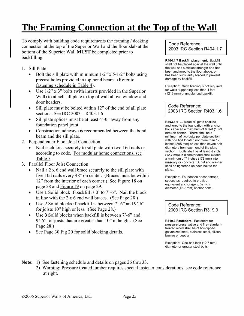
The Framing Connection at the Top of the Wall To comply with building code requirements the framing / decking connection at the top of the Superior Wall and the floor slab at the bottom of the Superior Wall MUST be completed prior to backfilling. 1. Sill Plate
• Bolt the sill plate with minimum 1/2” x 5-1/2” bolts using precast holes provided in top bond beam. (Refer to fastening schedule in Table 4).
• Use 1/2” x 3” bolts (with inserts provided in the Superior Wall) to attach sill plate to top of wall above window and door headers.
• Sill plate must be bolted within 12” of the end of all plate sections. See IRC 2003 – R403.1.6
• Sill plate splices must be at least 4’-0” away from any foundation panel joint.
• Construction adhesive is recommended between the bond beam and the sill plate.
2. Perpendicular Floor Joist Connection • Nail each joist securely to sill plate with two 16d nails or
according to code. For modular home connections, see Table 5.
3. Parallel Floor Joist Connection • Nail a 2 x 6 end wall brace securely to the sill plate with
five 10d nails every 48” on center. (Braces must be within 12” from the interior of each corner.) See Figure 18 on page 28 and Figure 19 on page 29.
• Use 1 Solid block if backfill is 0’ to 7’-6”. Nail the block in line with the 2 x 6 end wall braces. (See Page 28.)
• Use 2 Solid blocks if backfill is between 7’-6” and 9’-6” for joists 10” high or less. (See Page 28.)
• Use 3 Solid blocks when backfill is between 7’-6” and 9’-6” for joists that are greater than 10” in height. (See Page 28.)
• See Page 30 Fig 20 for solid blocking details.
R404.1.7 Backfill placement. Backfill shall not be placed against the wall until the wall has sufficient strength and has been anchored to the floor above, or has been sufficiently braced to prevent damage by backfill. Exception: Such bracing is not required for walls supporting less than 4 feet (1219 mm) of unbalanced backfill.
R403.1.6 … wood sill plate shall be anchored to the foundation with anchor bolts spaced a maximum of 6 feet (1829 mm) on center. There shall be a minimum of two bolts per plate section with one bolt located not more than 12 inches (305 mm) or less than seven bolt diameters from each end of the plate section….Bolts shall be at least ½ inch (12.7 mm) in diameter and shall extend a minimum of 7 inches (178 mm) into masonry or concrete…A nut and washer shall be tightened on each bolt to the plate… Exception: Foundation anchor straps, spaced as required to provide equivalent anchorage to ½ inch diameter (12.7 mm) anchor bolts.
R319.3 Fasteners. Fasteners for pressure preservative and fire-retardant-treated wood shall be of hot-dipped galvanized steel, stainless steel, silicon bronze or copper. Exception: One-half-inch (12.7 mm) diameter or greater steel bolts.
Note: 1) See fastening schedule and details on pages 26 thru 33.
2) Warning: Pressure treated lumber requires special fastener considerations; see code reference at right.
Code Reference: 2003 IRC Section R404.1.7
Code Reference: 2003 IRC Section R403.1.6
Code Reference: 2003 IRC Section R319.3

©2006 Superior Walls of America, Ltd. Page 26
The Framing Connection at the Top of the Wall Floor Connection: Joists Perpendicular to Superior Walls
Figure 16
1/2" Bolt
Treated Sill Plate(By Others)
Nail Each JoistUsing 2 - 16d Nails or
According to Code
Floor System(By Others)

©2006 Superior Walls of America, Ltd. Page 27
The Framing Connection at the Top of the Wall Floor Connection: Joists Perpendicular to Superior Walls
Figure 17

©2006 Superior Walls of America, Ltd. Page 28
The Framing Connection at the Top of the WallTable 4
Fastening Schedule Backfill Height
Sill Plate Bolting
Brace & Block Spacing
Number of Solid Blocks Required
Minimum Distance of Blocking
7’-6” – 9’-6” 24” OC 1 – 1/2” Bolt
3 for Joists over 10” High
5’-0”
7’-6” – 9’-6” 24” OC 1 – 1/2” Bolt
2 for Joists under 10” High
4’-0”
0’ < 7’-6” 48” OC 1 – 1/2” Bolt
48” OC / 12” from the
interior of each corner 1 2’-0”
Floor Connection: Joists Parallel to Superior Walls
(5) - 10d Nails
Treated Sill Plate
(2X6) End Wall Bracing
Solid Blocking
21 3
(6) - 10d Nails Through Plywood Into Solid Blocking
Minimum DistancePer Table 4
Figure 18

©2006 Superior Walls of America, Ltd. Page 29
The Framing Connection at the Top of the Wall Floor Connection: Joists Parallel to Superior Walls
Note: Brace and block spacing at 48” on center and within 12” from the interior of each corner.
Figure 19

©2006 Superior Walls of America, Ltd. Page 30
“I” Joist Blocking Detail
Figure 20
Treated Sill Plate
(5) - 10d Nails
Use "I Joist" Material,"Traditional Framing Lumber," or
Plywood Fabricated Blocking (Below)as Solid Blocking
(Engineered Lumber may have specificBlocking Requirements)
(2X6) End Wall Bracing
(6) - 10d Nails Through Plywood Into Solid Blocking
Minimum DistancePer Table 4
21 3
3/4" Plywood
Example of Plywood Fabricated Blocking
"d"
(2X4)
(6) - 10d Nails Through Plywood Into Blocking
(6) - 10d Nails (Typ.)
"d"

©2006 Superior Walls of America, Ltd. Page 31
(2X6) End Wall Bracing
Minimum DistancePer Table 4
(2X6) End Wall Bracing
Floor Truss Connections – Top Chord Bearing Parallel Truss
Figure 21 Perpendicular Truss
Figure 22

©2006 Superior Walls of America, Ltd. Page 32
Floor Truss Connections – Bottom Chord Bearing Parallel Truss
Minimum DistancePer Table 4
Concentrate (3) - 10d NailsAt Each (2X6) End Wall Brace
(5) - 10d NailsTreated Sill Plate
(2X6) End Wall Bracing
(6) - 10d Nails Through Plywood Into Solid Blocking
1 2
Nail Each Truss Using(2) - 16d Nails
or According to Code
Solid BlockingExample
Use "I Joist" Material,"Traditional Framing Lumber," or
Plywood Fabricated Blocking (See Page 30)as Solid Blocking
(Engineered Lumber may have specificBlocking Requirements)
Figure 24
Figure 23 Perpendicular Truss

©2006 Superior Walls of America, Ltd. Page 33
Modular Connection
• Use Superior Walls Framing Straps where it is difficult to nail the joists to the sill plate.
• The Framing Strap lies between the band joist and the sill plate and is fastened with 1-1/2” galvanized nails provided. Use 1 nail in every hole of the Framing Strap.
• Construction adhesive is recommended between the bond beam and the sill plate.
Table 5 Framing Strap Requirements
Backfill Height Framing Strap Spacing 7’-6” – 9’-6” 32” OC 0’ < 7’-6” 48” OC
10 1/4"
Treated Sill Plate
Framing Strap
Framing Strap
Top Bond Beam
1 2 3
(6) - 10d Nails ThroughPlywood Into Solid Blocking
orApply Construction Adhesive to Top
Surface of Blocking for FinishedModular Floors.
Sill Plate
Figure 25

©2006 Superior Walls of America, Ltd. Page 34
Typical Roof Truss Connection Detail
BackfillArea
1/2" Bolts(with Washers)
Virgin Soil1/2" Clean Stone
Fasten Each Truss Accordingto 2003 IRC Section R802
Slab Connector
CAUTION: DEPENDING ON PLAN DIMENSIONS, SITE CONDITIONS, AND DESIGN DETAILS, ROOF TRUSSES MAY REQUIRE STRUCTURAL CROSS BRACING AND / OR UPLIFT CLIPS. CONSULT YOUR DESIGN PROFESSIONAL.
Soffit
Figure 26

©2006 Superior Walls of America, Ltd. Page 35
Shear Wall
• A Shear wall may be required in certain uneven backfill or open floor plan conditions.
• Shear walls are required when the maximum wall lengths exceed the limits in Table 6 below, and must be individually reviewed by an engineer.
Table 6 Maximum Wall Length Without A Shear Wall
Soil Type Wall Height Differential Backfill Height SC, CL GM, SM, GC,
ML GW, GP, SW,
SP 8’-2” ≤ 7’-6”
≤ 7’-0” ≤ 6’-0”
27’-0” 32’-0” 52’-0”
36’-0” 44’-0” 70’-0”
54’-0” 66’-0” 105’-0”
9’-0” ≤ 8’-4” ≤ 7’-0” ≤ 6’-0”
21’-6” 36’-0” 58’-0”
29’-0” 48’-0” 76’-0”
42’-0” 72’-0” 116’-0”
10’-0” ≤ 9’-4” ≤ 8’-0” ≤ 7’-0” ≤ 6’-0”
18’-0” 27’-0” 40’-0” 64’-0” “X
i Onl
y” 23’-0”
36’-0” 54’-0” 86’-0”
34’-0” 54’-0” 80’-0” 128’-0”
• The calculations will change as the backfill heights change.
Figure 27

©2006 Superior Walls of America, Ltd. Page 36
Stairwell Header Procedure • Use details below for stairwell openings which are within 8
feet of basement walls. • The opening should not exceed 9’-6” in length. If a larger
opening is required consult an engineer or your Superior Walls supplier.
• Use construction adhesive between the sill plate and top bond beam of the Superior Wall.
• Build the support beam (2 x 10 sill plate and two 2 x 8’s) 2’-0” past each end of the opening without splices (see details below).
• Use ½” bolts in every hole; 2’-0” OC through the bond beam.
Allowable Backfill material for
9’-6” Stairwell Opening Wall Height (Xi / R5)
Soil Type 8’-2” * 9’ * 10’ *
GW, GP, SW, SP OK OK OK
GM, SM, GC, ML OK OK †
SC, CL OK † † † - Backfill with clean crushed stone. * - Maximum height of backfill is 6” below the top of the wall.
Effe
ctiv
e B
eam
/ Sp
ecia
l Bac
kfill
Are
a
Leng
th o
f Ope
ning
24"
24"
Effe
ctiv
e B
eam
/ Sp
ecia
l Bac
kfill
Are
a
Leng
th o
f Ope
ning
24"
24"
Bond Beam
(2x10) Sill Plate
2 - (2x8) Beam
Rim Joist
(2x10) Sill Plate2 - (2x8) Beam
9'-6
" Max
imum
9'-6
" Max
imum
Joists Perpendicular
(2X
4)'s
Nai
led
Thro
ugh
Subf
loor
Con
tinuo
us (2
X8)
Bea
m -
No
Splic
es
Joists Parallel
Con
tinuo
us (2
X8)
Bea
m -
No
Splic
es
(2x4) Every 2'-0" O.C.
Sill Plate Bolt
Bond Beam
Sill Plate Bolt
Solid BlockingPlywood Sub Floor
(2x4) Every 2'-0" O.C.
Sill Plate Bolt(2x4) Nailed ThroughSubfloor at Solid Block
Bond Beam
Plywood Sub FloorSolid Blocking
Floor Joists(Beyond)
Floor Joist Beyond
Figure 28 Figure 29

©2006 Superior Walls of America, Ltd. Page 37
Backfilling Recommendations WARNING: To comply with building code requirements, the framing / decking connection at the top of the Superior Wall and the floor slab at the bottom of the Superior Wall MUST be completed prior to backfilling! • It is the builder’s responsibility to insure proper site
conditions. • Do not use expansive soil or topsoil for backfill. See soil
chart Table 1 on page 5. • Backfill must not exceed 60 pounds per cubic foot
(PCF) equivalent fluid pressure (EFP) for any Superior Walls application.
• Maximum allowed height of backfill is 6” below the top of the Superior Wall.
• Always slope ground away from the foundation according to local code or not less than 6” fall within the first 10 feet. Provide functioning rain gutters, downspouts, and run-outs.
• Allowing heavy equipment to operate near backfilled walls may adversely affect your Superior Wall installation.
• In a condition where there is more backfill inside than outside, never exceed a 36” differential in fill heights.
Table 7
Backfill Requirements Product Line and Wall Heights Xi Walls R5 Walls
Soil Type All Heights
4’-0” / 4’-8”
8’-2” 9’-0” 10’-0”
GW, GP, SW, SP
OK OK OK OK OK
GM, SM, GC, ML
OK OK OK OK OK
SC, CL OK OK OK OK Fill with clean crushed stone
All Others Consult an Engineer
R401.3 Drainage. Surface drainage shall be diverted to a storm sewer conveyance or other approved point of collection so as to not create a hazard. Lots shall be graded so as to drain surface water away from foundation walls. The grade away from foundation walls shall fall a minimum of 6 inches (152 mm) within the first 10 feet (3048 mm). Exception: Where lot lines, walls, slopes or other physical barriers prohibit 6 inches (152 mm) of fall within 10 feet (3048 mm), drains or swales shall be provided to ensure drainage away from structure.
R404.1.6 Height above finished grade. Concrete and masonry foundation walls shall extend above the finished grade adjacent to the foundation at all points a minimum of 4 inches (102 mm) where masonry veneer is used and a minimum of 6 inches (152 mm) elsewhere.
R404.1.7 Backfill placement. Backfill shall not be placed against the wall until the wall has sufficient strength and has been anchored to the floor above, or has been sufficiently braced to prevent damage by backfill. Exception: Such bracing is not required for walls supporting less than 4 feet (1219 mm) of unbalanced backfill.
Code Reference: 2003 IRC Section R404.1.6
Code Reference: 2003 IRC Section R404.1.7
Code Reference: 2003 IRC Section R401.3

©2006 Superior Walls of America, Ltd. Page 38
Window Installation Details Always follow window manufacturer’s specifications.
Please Note: The window and door details shown here are examples only. When ordering, consider your project details carefully and specify the size of the Superior Walls’ concrete rough opening to suit your project needs. Remember to allow for things like brick returns and molding / trim clearance. Important: Always protect the concrete-embedded wood blocking from weather exposure. R5 New Construction Window Detail
Figure 30
Xi New Construction Window Detail
Figure 31
Interior FinishBy Others
WindowBy Others
Window TrimBy Others
Concrete Rough Opening
BlockingBy Others
Window TrimBy Others
Interior FinishBy Others
Concrete Rough Opening
WindowBy Others
BlockingBy Others

©2006 Superior Walls of America, Ltd. Page 39
Window Installation Details (cont)
Please Note: The window and door details shown here are examples only. When ordering, consider your project details carefully and specify the size of the Superior Walls’ concrete rough opening to suit your project needs. Remember to allow for things like brick returns and molding / trim clearance. Important: Always protect the concrete-embedded wood blocking from weather exposure. R5 Replacement Window Detail
Figure 32
Xi Replacement Window Detail
Figure 33
Concrete Rough Opening
Interior FinishBy Others
Window TrimBy Others
WindowBy Others
Interior FinishBy Others
WindowBy Others
Window TrimBy Others
Concrete Rough Opening

©2006 Superior Walls of America, Ltd. Page 40
Window Installation Details (cont)
Please Note: The window and door details shown here are examples only. When ordering, consider your project details carefully and specify the size of the Superior Walls’ concrete rough opening to suit your project needs. Remember to allow for things like brick returns and molding / trim clearance. Important: Always protect the concrete-embedded wood blocking from weather exposure.
R5 Window Detail (with Brick Veneer)
Interior FinishBy Others
WindowBy Others
Window TrimBy Others
Rough Opening Dimensioned to Here
Figure 34
Xi Window Detail (with Brick Veneer)
Interior FinishBy Others
Window TrimBy Others
WindowBy Others
Rough Opening Dimensioned to Here
Figure 35

©2006 Superior Walls of America, Ltd. Page 41
Door Installation Detail Always follow door manufacturer’s specifications.
Please Note: The window and door details shown here are examples only. When ordering, consider your project details carefully and specify the size of the Superior Walls’ concrete rough opening to suit your project needs. Remember to allow for things like brick returns and molding / trim clearance. Important: Always protect the concrete-embedded wood blocking from weather exposure. R5 New Construction Door Detail
Figure 36 Xi New Construction Door Detail
Figure 37
TrimBy Others
Interior FinishBy Others
DoorBy Others
BlockingBy Others
Concrete Rough Opening
TrimBy Others
Interior FinishBy Others
BlockingBy Others
DoorBy Others
TrimBy Others
TrimBy Others
Concrete Rough Opening

©2006 Superior Walls of America, Ltd. Page 42
Door Installation Detail (cont)
Please Note: The window and door details shown here are examples only. When ordering, consider your project details carefully and specify the size of the Superior Walls’ concrete rough opening to suit your project needs. Remember to allow for things like brick returns and molding / trim clearance. Important: Always protect the concrete-embedded wood blocking from weather exposure.
R5 Replacement Door Detail
Figure 38
Xi Replacement Door Detail
Figure 39
Interior FinishBy Others
TrimBy Others
DoorBy Others
TrimBy Others
Concrete Rough Opening
Interior FinishBy Others
DoorBy Others
TrimBy Others
TrimBy Others
Concrete Rough Opening
©2006 Superior Walls of America, Ltd. Page 43
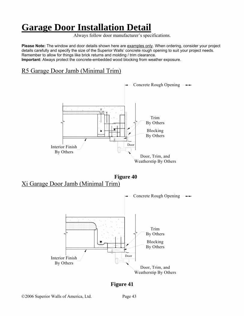
Garage Door Installation Detail Always follow door manufacturer’s specifications.
Please Note: The window and door details shown here are examples only. When ordering, consider your project details carefully and specify the size of the Superior Walls’ concrete rough opening to suit your project needs. Remember to allow for things like brick returns and molding / trim clearance. Important: Always protect the concrete-embedded wood blocking from weather exposure.
R5 Garage Door Jamb (Minimal Trim)
Figure 40 Xi Garage Door Jamb (Minimal Trim)
Figure 41
DoorInterior FinishBy Others
Door, Trim, andWeatherstip By Others
TrimBy Others
BlockingBy Others
Concrete Rough Opening
DoorInterior FinishBy Others
BlockingBy Others
TrimBy Others
Door, Trim, andWeatherstip By Others
Concrete Rough Opening

©2006 Superior Walls of America, Ltd. Page 44
Garage Door Installation Detail (cont’d)
Please Note: The window and door details shown here are examples only. When ordering, consider your project details carefully and specify the size of the Superior Walls’ concrete rough opening to suit your project needs. Remember to allow for things like brick returns and molding / trim clearance. Important: Always protect the concrete-embedded wood blocking from weather exposure.
R5 Garage Door Jamb (Ornate Trim)
Figure 42
Xi Garage Door Jamb (Ornate Trim)
Figure 43
Interior FinishBy Others
Door, Trim, andWeatherstip By Others
Door
BlockingBy Others
TrimBy Others
Concrete Rough Opening
Door, Trim, andWeatherstip By Others
Interior FinishBy Others
TrimBy Others
BlockingBy Others
Door
Concrete Rough Opening

©2006 Superior Walls of America, Ltd. Page 45
Point Loading It is important to identify any concentrated load that will rest directly on the sill plate or bond beam.
• The maximum uniform load capacity on top of the Superior Wall is 4000 pounds per linear foot (PLF).
• When ordering, identify any concentrated load exceeding 3000 pounds that rests directly on the bond beam or the sill plate, so that the factory can evaluate it and provide the proper structural members to support it.
Beam Pockets Beam pockets are designed to support beams that will be located below floor joists. When ordering, always specify the location, size (width and height) and design loading.
R606.13 Beam supports. Beams, girders or other concentrated loads supported by a wall or column shall have a bearing of at least 3 inches (76 mm) in length measured parallel to the beam upon solid masonry not less than 4 inches (102 mm) in thickness, or upon a metal bearing plate of adequate design and dimensions to distribute the load safely, or upon a continuous reinforced masonry member projecting not less than 4 inches (102 mm) from the face of the wall.
Figure 44
Code Reference: 2003 IRC Section R606.13

©2006 Superior Walls of America, Ltd. Page 46
Pre-cast Column Pads • Precast column pads may be ordered for the support of columns
designed for the loads indicated on the following charts. Consider soil bearing capacity and stone depth requirements when selecting. Interpolation for other soil values is permitted.
• Load values assume a 6” x 6” column base. Table 8
2’ x 2’ x 4-1/2” Column Pad Depth
of Stone
Excavation Width
(Minimum)
Allowable load, Based on soil bearing capacity (psf)
2000 psf soil 3000 psf soil 0” 2’-0” 8000 lbs 12,000 lbs 2” 2’-3” 9620 lbs 14,430 lbs 4” 2’-5” 11,375 lbs 15,400 lbs* 6” 2’-7” 13,285 lbs 15,400 lbs* 8” 2’-10” 15,400 lbs* 15,400 lbs*
Table 9 3’ x 3’ x 6” Column Pad
Depth of
Stone
Excavation Width
(Minimum)
Allowable load, Based on soil bearing capacity (psf)
2000 psf soil 3000 psf soil 0” 3’-0” 18,000 lbs 27,000 lbs 2” 3’-3” 20,380 lbs 28,000 lbs* 4” 3’-5” 22,920 lbs 28,000 lbs* 6” 3’-7” 25,600 lbs 28,000 lbs* 8” 3’-10” 28,000 lbs* 28,000 lbs*
*Note: Maximum allowable load limited by punching shear.
Table 10 28” Dia x 4 ½” Round Column Pad Depth
of Stone
Excavation Width
(Minimum)
Allowable load, Based on soil bearing capacity (psf)
2000 psf soil 3000 psf soil 0” 2’-4” 8,000 lbs 12,000 lbs 4” 2’-9” 11,000 lbs 17,000 lbs 6” 2’-11” 13,000 lbs 19,000 lbs 8” 3’-2” 15,000 lbs 22,000 lbs 10” 3’-4” 17,000 lbs 25,000 lbs 12” 3’-6” 19,000 lbs 28,000 lbs
Figure 45
Figure 46
Figure 47
Concrete FloorBy Others
Structural ColumnBy Others
24" X 24" X 4 1/2"Column Pad
Load Transfer Width(Excavation Width)
#3 Rebar
Depth of Stone
Structural ColumnBy Others
Concrete FloorBy Others
36" X 36" X 6"Column Pad
# 4 Rebar
Depth of Stone
Load Transfer Width(Excavation Width)
Concrete FloorBy Others
Structural ColumnBy Others
28" Dia. X 4 1/2"Round Column Pad
Load Transfer Width(Excavation Width)
#4 Rebar
Depth of Stone

©2006 Superior Walls of America, Ltd. Page 47
Support Ledges
• You may specify either a 4” or 6” projection for ledges to support:
Brick or stone veneers Adjoining walls Garage, porch or patio floor pours
These ledges may be either continuous or intermittent. You must specify their vertical and horizontal location.
• Wall ties are needed when the ledge is intended to support masonry veneers and is 16” or more below the top of the Superior Wall.
• 4” and 6” support ledges are rated for 2,900 pounds per linear foot.
• See building code reference for flashing requirements.
Specify 4" or 6"Ledge Projection
Figure 48
R703.7.4.2 Air space. The veneer shall be separated from the sheathing by an air space a minimum of 1 inch (25.4 mm) but not more than 4-1/2 inches (114 mm). The weather-resistant membrane or asphalt-saturated felt required by Section R703.2 is not required over water-repellent sheathing materials.
R703.7.4.3 Mortar or grout fill. As an alternate to the air space required by Section R703.7.4.2, mortar or grout shall be permitted to fill the air space. When the 1-inch (25.4 mm) space is filled with mortar, a weather-resistant membrane or building paper is required over studs or sheathing. When filling the air space, it is permitted to replace the sheathing and weather-resistant membrane or asphalt-saturated felt paper with a wire mesh and approved paper or an approved paper-backed reinforcement attached directly to the studs.
R703.7.5 Flashing. Flashing shall be located beneath the first course of masonry above finished ground level above the foundation wall or slab and at other points of support, including structural floors, shelf angles and lintels when masonry veneers are designed in accordance with Section R703.7. See Section R703.8 for additional requirements.
Code Reference: 2003 IRC Section R703.7.4.2
Code Reference: 2003 IRC Section R703.7.4.3
Code Reference: 2003 IRC Section R703.7.5

©2006 Superior Walls of America, Ltd. Page 48
Interior Finishing of Superior Walls
90 DEGREE OUTSIDE CORNER
Cut (2x4) Cut (2x4)
45 DEGREE OUTSIDE CORNER
Drywall
Wood Blocking(By Others)
90 DEGREE INSIDE CORNER 90 DEGREE INSIDE CORNER
Figure 49

©2006 Superior Walls of America, Ltd Homeowner Guide Appendix A
HOMEOWNER GUIDE Rev: 11/23/05 Additional copies of this Homeowner Guide are available for download at www.superiorwalls.com. Controlling Humidity and Condensation Modern construction methods have resulted in tighter, more energy-efficient homes that require planning for the control of humidity and condensation. Because a Superior Walls wall panel is constructed with a high-performance concrete mix and lined with closed-cell foam insulation, it prevents the free flow of moisture through the wall panel. Though this is a good thing when seeking to keep ground water out of your basement; it also acts to keep moisture vapor inside the house. In certain conditions of high interior humidity and low exterior temperatures, it is possible that condensation may form on the interior surface of the Superior Walls panel. Condensation can occur anytime moist air contacts a surface that has a temperature less than the dew-point of the air. Condensation may be controlled in a number of ways:
1. By reducing the amount of moisture in the air: a. Limit moisture-producing sources or activities like non-vented clothes dryers, space heaters or hot-tubs. b. Use a dehumidifier.
2. By preventing the moisture from reaching the cold wall surface: a. Use a vapor barrier (vapor retarder). b. Remove the moist air with an exhaust fan or other ventilation.
3. By increasing the temperature of the room: a. Add heat and the air will hold more moisture. b. Increase the room temperature and you will also increase the temperature of the wall surface.
It is usually most effective to use more than one of these methods in order to effectively control condensation.
“Original Equipment” Foam Insulation All Superior Walls products are tested to the UL1715 fire test standard and comply with the requirements of the 2003 International Residential Code - Section R314 (Foam Plastic) and Section R315 (Flame Spread and Smoke Density). No additional thermal barrier is required UNLESS additional foam insulation has been added after the panel was manufactured. Superior walls are delivered to your job site with either 1” or 2½” foam insulation installed as a part of the system. This gives the walls an R-5 or R-12.5 rating respectively.
Exterior Helpful Hints ● Grade – Slope the ground away from the home a minimum of 6 inches within the first 10 feet from the wall (additional slope may be required by your local building code). ● Gutters and Downspouts - Keep gutters and downspouts free of leaves and debris. Splash blocks or down spout extensions should be used to divert water away from the foundation.
Interior Finishing of Superior Walls • Corner Studs and Blocking – Always use preservative-treated lumber for corner studs and nailers placed against
the concrete. For areas where there will be objects fastened to the finished walls between existing studs, install appropriate wood blocking. (i.e. For curtain rods, cabinets, doorstops, or electrical and plumbing fixture locations.)
• Wiring and Plumbing – Using the pre-cast holes in the studs, install all electrical wiring and small plumbing lines according to local codes. Holes may be drilled through the top bond beam for wiring and plumbing drops.
• Drywall and Interior Finishes – After the corner studs and all blocking are in place, the Superior Walls are ready for drywall. Regular ½” drywall is recommended to span the stud spacing. It is best to leave a ½” gap between the concrete floor and the bottom of the drywall to prevent moisture absorption into the drywall. This moisture can cause
©2006 Superior Walls of America, Ltd Homeowner Guide Appendix A
drywall deterioration and paint finish problems. Attach the drywall using 1” drywall screws. A solid bead of construction adhesive should be applied to the top bond beam and the face of the stud. The use of paneling or other similar products should still be backed with a layer of drywall.
• Exterior Holes in Superior Wall Panels – Any exterior holes that may be required for such things as sanitary soil lines, electrical service entrance cables, or chimney flues, should be made following these simple procedures: 1. Mark-out the location and size of the hole required. 2. Use a masonry hole saw or a hammer drill with a small bit (to drill a series of holes around the perimeter of the
hole). With a hammer and chisel start to work the area inside the small holes until the hole is the required size and shape.
3. After the pipe is installed, completely seal the entire area around it with a flexible sealant to prevent water penetration. A one part urethane or polyurethane is recommended. (Do not use Acytoxy-cure silicones.)
Adding Insulation to a Superior Walls Panel When adding insulation to a Superior Walls wall panel, it is important to consider two factors to ensure that water vapor does not condense within the wall cavity: 1. Controlling the moisture content of the air trapped in the cavity while adding the insulation. (It may be necessary to use a
dehumidifier.) 2. Restricting moisture-laden air from entering the cavity from the living space or from the earth beneath the wall. (This may
be accomplished through the use of vapor barriers, sealants, and spray foams. Daylight drains require a trap on the drain line to prevent a back-flow of moist air.)
The essential issue is that you must stop moisture from entering the stud cavity.
• Fiberglass batt, cellulose, Icynene®, or other materials may perform satisfactorily if the considerations noted above are properly dealt with.
There are two other methods that will consistently yield satisfactory results and prohibit condensation from forming within the wall cavity:
• Spray-on 2-part polyurethane foam. This is a closed cell material and completely closes off the cavity from moisture
penetration. It can be obtained both professionally and as a DIY kit. Several DIY kits are available on the internet. • Add extruded/expanded polystyrene foam board between the studs, and seal between the foam board and studs with
a (“great stuff-type”) canned polyurethane. The polystyrene foam board is closed cell; moisture cannot pass through, and when used in conjunction with the canned foam, completely closes off the cavity from moisture penetration. Foam board is readily available for the DIY market, as is the canned polyurethane foam.
Generally speaking, after adding any type of exposed foam insulation to the interior of a wall assembly, the building code requires that you cover the insulation with a thermal barrier to protect the insulation from fire - see your local building code for details. NOTE: This information is general in nature and may not be applicable in every situation. Your design professional (i.e. builder, architect, engineer, or supplier) can assist you in special conditions. When in doubt, please ask for guidance concerning your particular application.

©2006 Superior Walls of America, Ltd Builder’s Checklist Appendix B
BUILDER’S CHECKLIST Rev: 11/23/05 All page references made below use the Superior Walls of America Builder Guideline Booklet (Revised January 2006) and the 2003 International Residential Code. Additional copies of this checklist are available for download at www.superiorwalls.com.
1. Provide your local Superior Walls representative with:
Floor plans and elevations Total pounds per linear foot on the foundation Beam and column locations, sizes and point loads Additional point loads and locations Window and door locations, rough opening sizes Egress Considerations Exterior finishes requiring support ledges Interior stairway locations, opening sizes (affects panel lengths) Inside fill conditions Exterior basement entry system specifications Chimney details
2. Prepare Site:
Building Permits and Inspections Soils Verification Excavation Placement of Drain Pipe and Sump Pit Installation of Filter Membrane Cold Weather Practice Placement of Crushed Stone Footing Locate Building Corner Pins and Establish Grade Site Accessibility for Trucks and Crane Installation of Sill Plate and Framing Attachments Backfilling After Concrete Floor has been Poured and Floor Framing has been Completed
3. Provide checklist from Builder Guideline Booklet for:
Excavation Concrete floor Framing Inspection
4. Provide approved drawings (Date: _______ Revision: _______) for:
Excavation Concrete Framing
5. Soil characteristics (Pg. 5)
Determine type _____ and allowable foundation pressure _________(Table 1 on Pg. 5) Determine combined footing load per linear foot __________
6. Crushed stone footing (Pg. 6)
Determine stone depth (Table #2 on Pg. 6) __________ Communicate stone depth to excavator
7. Excavation (Pg. 8)
Provide elevations
©2006 Superior Walls of America, Ltd Builder’s Checklist Appendix B
Set corner pins Communicate to excavator: site accessibility needs (trucks and crane)
8. Drain system and daylight drain or sump (Pg. 6, 7 & 9)
Communicate to excavator: placement of perforated drain pipe in reference to corner pin location (Figure 1 on Pg. 6, Table 3 on Pg. 7)
Communicate to excavator: location of daylight drain and trap (Pg. 9) or location of sump accumulation tank(s)
Install filter membrane
9. Shear walls (Pg. 35) Verify need for shear walls with SWA representative If required, verify that shear walls are attached to floor, outside wall and joist(s) above Choose shear wall construction: ___ Superior Wall panel or ___ 2 x 6 stud wall with ½” plywood
attached both sides If stud wall, communicate construction to framers
10. Basement concrete floor (Pg. 19)
NOTE: To comply with building code and Superior Walls of America, Ltd. requirements, the framing / decking connection at the top of the Superior Wall and the floor slab at the bottom of the Superior Wall MUST be completed prior to backfilling!
Communicate need to embed Superior Walls Slab Connector (if included) into concrete floor pour
Communicate thickness (3 ½”), sub base (4”), concrete psi, vapor retarder under floor (as required per code), and floor reinforcement if required
11. Crawl space (Pg. 21 & 22): Choose one of the following:
Treated wooden bracing at 48” O.C., or 12” minimum inside fill, or 2”, minimum, poured concrete floor
12. Framing / Modular connection (Pg. 25 to 34)
NOTE: To comply with building code requirements, the framing / decking connection at the top of the Superior Wall and the floor slab at the bottom of the Superior Wall MUST be completed prior to backfilling!
Determine fastening schedule (Table #4 on Pg 28) ( _____” OC) Communicate fastening schedule to framers Bolted not more than 12” from the ends of each sill plate section (R403.1.6) Framing strap (if used) lies between band joist and sill plate (Figure #25 on Pg. 33), is fastened
with 1 ½” nails provided, 1 nail per hole, Verify strap spacing (Table #5 on Pg. 33)
13. Electrical / Plumbing Communicate proper method to drill / cut holes through Superior Wall.
Exterior Holes in Superior Wall Panels – Any exterior holes that may be required for such things as sanitary soil lines, electrical service entrance cables, or chimney flues, should be made following these simple procedures:
1. Mark-out the location and size of the hole required. 2. Use a masonry hole saw or a hammer drill with a small bit (to drill a series of
holes around the perimeter of the hole). With a hammer and chisel start to work the area inside the small holes until the hole is the required size and shape.
3. After the pipe is installed, completely seal the entire area around it with a flexible sealant to prevent water penetration. A one part urethane or polyurethane is recommended. (Do not use Acytoxy-cure silicones.)

©2006 Superior Walls of America, Ltd Excavator’s Checklist Appendix C
EXCAVATOR’S CHECKLIST Rev: 11/23/05 All page references made below use the Superior Walls of America Builder Guideline Booklet (Revised January 2006) and the 2003 International Residential Code. Additional copies of this checklist are available for download at www.superiorwalls.com.
1. Builder Guideline Booklet
Obtain your personal copy of the SWA Builder’s Guideline Booklet
2. Site drawings Confirm you are working from the approved drawing before you dig Drawing date:____________ Drawing Rev:_______________
3. Building placement
Obtain required benchmark elevations from builder Excavate per set pins from builder
4. Excavation (Pg. 8)
Trench dug below frost line Verify with builder either: ____sump pump or _____ daylight drain If sump pump, number of accumulation tanks _______ Provide minimum 2’-0” over-dig at base of foundation (both sides of wall) (Pg. 8 & 14) Properly bench banks (for foundations more than 7’-6” deep, bench 2’-0” for every 5’-0” of
depth) Provide ramp for access to hole if required Pile soil a safe distance from hole Excavate for column pads as required
5. Crushed stone footing (Pg. 6)
Obtain required stone depth from builder (___inches) Dig footing per required stone depth (Table #2 on Pg. 6) Use 4 inch perforated pipe (Figure 1 on Pg. 6) and locate pipe (Table 3 on Pg. 7) Place drain pipe (Figure 1 on Pg. 6 and Table 3 on Pg. 7) Clean crushed stone (1/2” Max), washed gravel (3/4” Max), or coarse sand (Not smaller than
1/16") Consolidate stone in a maximum of 8” lifts with plate vibrator Direct drain pipe to accumulation tank(s) or daylight Evenly grade the stone to +/- 1 inch of level Leave enough stone behind for use in final grading by the wall installation crew Install filter membrane on top of stone footing prior to backfill (R405.1)
6. Basement concrete floor (Pg. 19)
Clean 4” base provided (R506.2.2)
7. Backfilling (Pg. 37) Get approval to backfill from builder
NOTE: To comply with building code requirements, the framing / decking connection at the top of the Superior Wall and the floor slab at the bottom of the Superior Wall MUST be completed prior to backfilling!

©2006 Superior Walls of America, Ltd Excavator’s Checklist Appendix C
8. Final grading (Pg. 37) Slope the final soil grade a minimum of 6” fall within the first 10’-0” to divert ground water away
from foundation (Pg. 37) Finished soil grade must be at least 6” below to of the Superior Wall (Pg. 37 )

©2006 Superior Walls of America, Ltd Concrete Work Checklist Appendix D
CONCRETE WORK CHECKLIST Rev: 11/23/05 All page references made below use the Superior Walls of America Builder Guideline Booklet (Revised January 2006) and the 2003 International Residential Code. Additional copies of this checklist are available for download at www.superiorwalls.com.
1. Builder Guideline Booklet Obtain your personal copy of the SWA Builder’s Guideline Booklet
2. Building drawings
Confirm you are working from the approved drawing Drawing date:____________ Drawing Rev:_______________
3. Crawl space (Pg. 21 & 22): Confirm, with builder, one of the following:
Treated wooden bracing at 48” OC, or 12” minimum inside fill, or 2” poured concrete floor
4. Basement concrete floor (Pg. 19)
Clean 4” base (R506.2.2) Install vapor retarder under floor pour as required by local code (R506.2.3) 3 ½” thick minimum floor thickness (R506.1) Fasten lath at the desired height of the concrete floor to form a screed board Bend slab connectors (if present) down before pouring concrete floor Provide 2” minimum concrete contact between base of wall and concrete floor
5. Raised concrete floor (at a level higher than the typical elevation) (Pg. 20)
Clean 4” base (R506.2.2) Install vapor retarder under floor pour as required by local code (R506.2.3) 3 ½” thick minimum floor thickness (R506.1) Fasten lath at the desired height of the concrete floor to form a screed board Cut and remove foam insulation at the desired floor surface Cut and remove the interior wooden stud facing at the desired floor surface

This page left intentionally blank.

©2006 Superior Walls of America, Ltd Framer’s Checklist Appendix E
FRAMER’S CHECKLIST Rev: 11/23/05 All page references made below use the Superior Walls of America Builder Guideline Booklet (Revised January 2006) and the 2003 International Residential Code. Additional copies of this checklist are available for download at www.superiorwalls.com.
1. Builder Guideline Booklet Obtain your personal copy of the SWA Builder’s Guideline Booklet
2. Building drawings
Confirm you are working from the approved drawing Drawing date:____________ Drawing Rev:_______________
3. Crawl space (Pg. 21 & 22): Confirm, with builder, one of the following:
Treated wooden bracing at 48” OC, or 12” minimum inside fill, or 2” poured concrete floor
4. Sill plate framing connection (Pg. 25 to 27)
Obtain sill plate bolting frequency from builder (Table #4 on page 28) (__24” OC or ___ 48” OC)
Use ½” x 5 ½” (minimum length) bolts with washers in top bond beam Fasten above window & door headers (Pg. 25) Use a minimum of 2 bolts per sill plate section and Bolted not more than 12” from the ends of each sill plate section (R403.1.6) Sill plate splices are at least 48” from any foundation panel joint
5. Perpendicular floor joist connection (Pg. 25)
Each joist nailed to sill plate with two 16d nails (or three 8d nails per code)
6. Parallel floor joist connection (Pg. 25) 2 x 6 end-wall braces and joist blocking located every 48” and within 12” from the interior of
each corner (Figures 18 & 19 on Pg. 28 & 29) Nail same 2 x 6 end-wall brace to sill plate with five 10d nails Obtain number of solid blocks required from builder _________ 1 solid block used if backfill is 0’ to 7’-6” 2 solid blocks used if backfill is between 7’-6” and 9’-6” for joist 10” high or less 3 solid blocks used if backfill is between 7’-6” and 9’-6” for joist that are greater than 10” high.
(See fastening details on Pg. 26 to 33) Blocking requires six 10d nails through floor (conventional construction) or construction
adhesive on top of blocking (modular construction) (Pg.33)
7. Modular connection (Pg. 33) Obtain required spacing (32” or 48” OC) for framing straps from builder (Table #5 on Pg. 33) Install framing straps between band joist and sill plate (Figure #25 on Pg. 33) Nail framing strap with 1 ½” nails provided with straps 1 nail in every nail hole

©2006 Superior Walls of America, Ltd Framer’s Checklist Appendix E
8. Wooden Shear wall (Pg. 35)
Determine from builder if a wooden shear wall is required ( ___ Yes ____ No) (Wooden shear wall is a 2 x 6 stud wall with ½” plywood attached both sides)
Shear wall attached to concrete floor, wall and floor joist(s) above
9. Stairwell header (Pg. 36). Is the long side of the stairway opening within 8’ of the parallel Superior Wall? If “YES”:
o Support beam (2 x 10 sill plate and two 2 x 8’s) 2’–0” past each end of the opening without splices
o Bolts must be present every 2’-0” OC through the beam o Openings larger than 9’-6” must be reviewed by an engineer
10. Roof truss connections (Pg. 34) Obtain sill plate bolting frequency from builder per table #4 on page 28 (__24” OC or ___ 48”
OC) Verify with builder what structural cross bracing (for wind loads or backfill) is required for the
trusses (per manufacturer’s specs) Verify with builder if uplift clips are required for the trusses
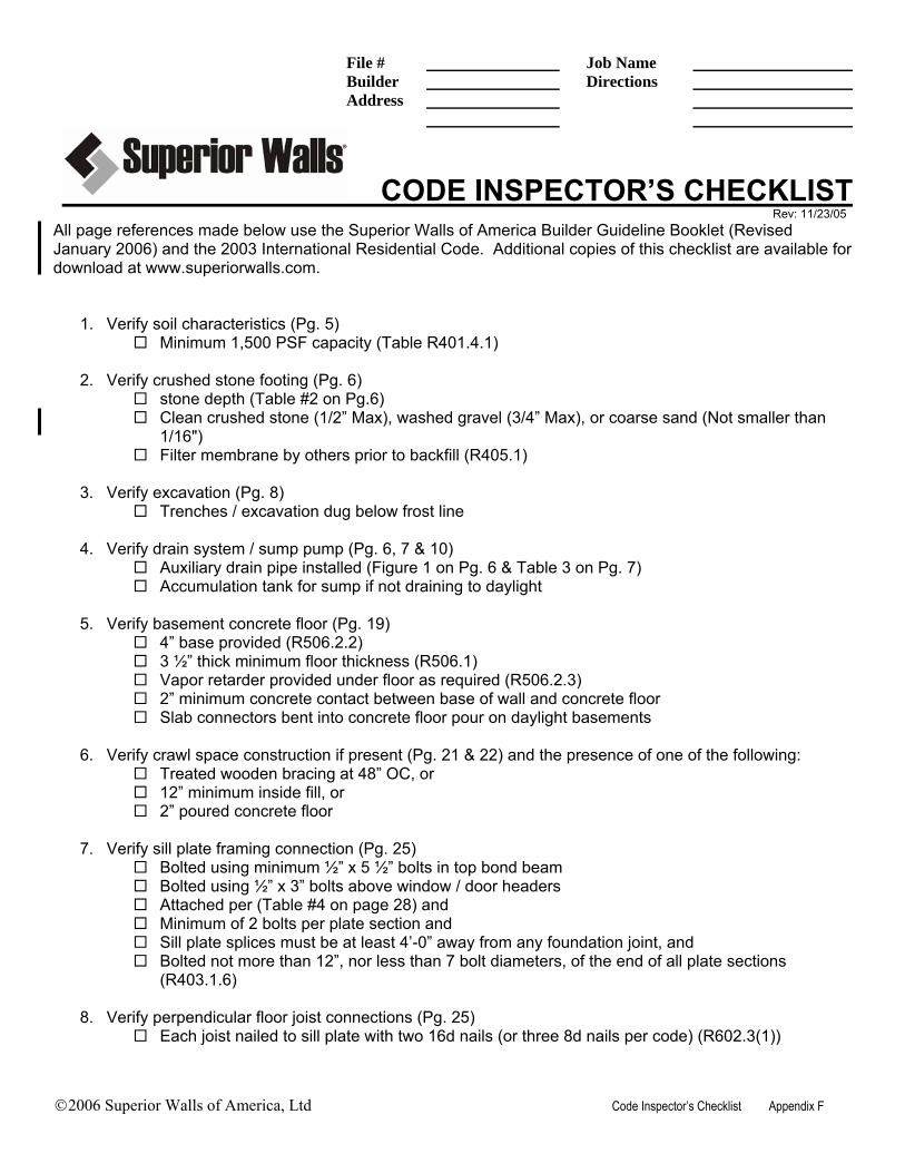
File # Job Name Builder Directions Address
©2006 Superior Walls of America, Ltd Code Inspector’s Checklist Appendix F
CODE INSPECTOR’S CHECKLIST Rev: 11/23/05 All page references made below use the Superior Walls of America Builder Guideline Booklet (Revised January 2006) and the 2003 International Residential Code. Additional copies of this checklist are available for download at www.superiorwalls.com.
1. Verify soil characteristics (Pg. 5) Minimum 1,500 PSF capacity (Table R401.4.1)
2. Verify crushed stone footing (Pg. 6)
stone depth (Table #2 on Pg.6) Clean crushed stone (1/2” Max), washed gravel (3/4” Max), or coarse sand (Not smaller than
1/16") Filter membrane by others prior to backfill (R405.1)
3. Verify excavation (Pg. 8)
Trenches / excavation dug below frost line
4. Verify drain system / sump pump (Pg. 6, 7 & 10) Auxiliary drain pipe installed (Figure 1 on Pg. 6 & Table 3 on Pg. 7) Accumulation tank for sump if not draining to daylight
5. Verify basement concrete floor (Pg. 19)
4” base provided (R506.2.2) 3 ½” thick minimum floor thickness (R506.1) Vapor retarder provided under floor as required (R506.2.3) 2” minimum concrete contact between base of wall and concrete floor Slab connectors bent into concrete floor pour on daylight basements
6. Verify crawl space construction if present (Pg. 21 & 22) and the presence of one of the following:
Treated wooden bracing at 48” OC, or 12” minimum inside fill, or 2” poured concrete floor
7. Verify sill plate framing connection (Pg. 25)
Bolted using minimum ½” x 5 ½” bolts in top bond beam Bolted using ½” x 3” bolts above window / door headers Attached per (Table #4 on page 28) and Minimum of 2 bolts per plate section and Sill plate splices must be at least 4’-0” away from any foundation joint, and Bolted not more than 12”, nor less than 7 bolt diameters, of the end of all plate sections
(R403.1.6)
8. Verify perpendicular floor joist connections (Pg. 25) Each joist nailed to sill plate with two 16d nails (or three 8d nails per code) (R602.3(1))

©2006 Superior Walls of America, Ltd Code Inspector’s Checklist Appendix F
9. Verify parallel floor joist connections (Pg. 25)
2 x 6 end-wall braces located within 12” from the interior of each corner (Figures 18 & 19 on Pg. 28 & 29)
Same 2 x 6 end-wall braces nailed to sill plate with five 10d nails 1 solid block used if backfill is 0’ to 7’-6” (nailed in-line with the 2 x 6 end-wall brace) 2 solid blocks used if backfill is between 7’-6” and 9’-6” for joists 10” high or less 3 solid blocks used if backfill is between 7’-6” and 9’-6” for joists that are 10” or higher (See
fastening details on Pg. 26 to 33) Blocking requires six 10d nails through floor (conventional construction) or construction
adhesive on top of blocking (modular construction)
10. Verify modular connection (Pg. 33) Framing strap lies between band joist and sill plate (Figure #25 on Pg. 33) Framing strap is fastened with 1 ½” nails provided with straps Verify 1 nail per hole Verify strap spacing (Table #5 on Pg. 33)
11. Verify shear walls (Pg. 35)
If present, verify that shear wall is attached to floor, outside wall and joist(s) above Shear wall must be either a Superior Wall panel or a 2 x 6 stud wall with ½” plywood attached
both sides
12. Verify stairwell header (Pg. 36). Is the long side of the stairway opening within 8’ of the parallel Superior Wall? If “YES”:
Support beam (2 x 10 sill plate and two 2 x 8’s) 2’–0” past each end of the opening without splices)
Bolts must be present every 2’-0” OC through the beam Openings larger than 9’-6” must be reviewed by an engineer
13. Verify backfilling (Pg. 37)
Before backfilling, basement floor must be poured and first floor framing / decking properly attached (R404.1.7)
Height of finished soil grade must be at least 6” below top of Superior Wall (R404.1.6)
14. Verify inside fill conditions (Pg. 23) Must not exceed 36” more inside fill than outside fill
15. Verify final grade
Slope the final soil grade a minimum of 6” fall within the first 10’-0” to divert ground water away from foundation (R401.3)
Height above finished soil grade must be at least 6” (R404.1.6)

©2006 Superior Walls of America, Ltd BGB Suggestion for Improvement Appendix G
Suggestion for Improvement Rev: 11/23/05 So that we may continually improve upon the quality of the materials we offer, please take a few moments to complete this Suggestion for Improvement form. General Information Name: _________________________ Address: _________________________ City: _________________________ State: _________________________ Zip: _________________________ Phone: _________________________ E-mail: _________________________ Please rate the following:
Content / Technical Level Disagree Neutral Agree Information in this publication is presented in a logical fashion . . . . ○ ○ ○ Each topic / section flowed smoothly to the next . . . . . . . . . . . . . . . ○ ○ ○ The content of each topic / section is sufficient . . . . . . . . . . . . . . . . ○ ○ ○
If you disagree, was it: Too much? ○ Too Little? ○ Comments / Suggestions: ________________________________________________________________________________________________________________________________________________________________________________________________________________________________________________________________________________________________________________________________________________________________________________________________________________________________________________________________________________________________________________________________________________________________________________________________________________________________________________________________________________________________________________________________________________________________________________________________________________________________________________________________________________________________________________ ________________________________________________________________________________________________________________________________________________________________________________________________________________________________________________________________________________________________________________________________________________________________________________________________________________________________________________________________________________________________________________________________________________________________________________________________________________________________________________________________________________________________________________________________________________________________________________________________________________________________________________________________________________________________________________
Please fax or mail this completed form to: Superior Walls of America, Ltd. Attn: Builder Guideline Booklet Committee 937 East Earl Road New Holland, PA 17557 Phone: (800) 452-9255 Fax: (717) 351-9264

This page left intentionally blank.


NOTES