Embed Size (px)
Citation preview
Sun Storage 2500-M2 ArraysGetting Started Guide
This document provides an overview of the installation procedure for Oracle’s Sun Storage 2500-M2 Arrays,including:
■ Sun Storage 2540-M2 array (controller tray with Fibre Channel host connectivity)
■ Sun Storage 2530-M2 array (controller tray with SAS-2 host connectivity)
■ Sun Storage 2501-M2 array (expansion tray)
For detailed information, have the Sun Storage 2500-M2 Arrays Hardware Installation Guide available as you gothrough the steps in this document.
Additional documentation is listed in the section “Documentation for This Product” and available at the Oracledocumentation web site:
http://www.oracle.com/technetwork/documentation/oracle-unified-ss-193371.html
Sun Storage Common Array ManagerOracle’s Sun Storage Common Array Manager (CAM) software is a key component for the initial configurationand operation of Sun Storage 2500-M2 Arrays hardware. It is installed on a management host cabled to the arrayvia out-of-band Ethernet (cables for this connection are provided). Note: In-band management is also supported.
To download and get started with CAM, review the latest Sun Storage Common Array Manager Quick Start Guide.CAM documentation can be found here:
http://www.oracle.com/technetwork/documentation/disk-device-194280.html
Note – It is recommended to begin the download process now so that the software is ready for installation whenhardware installation is complete.
Before You BeginReview the following documents before starting the installation:
• Important Safety Information for Sun Hardware Systems • Sun Storage 2500-M2 Arrays Hardware Release Notes
• Sun Storage 2500-M2 Arrays Safety and Compliance Manual • Sun Storage 2500-M2 Arrays Site Preparation Guide
1
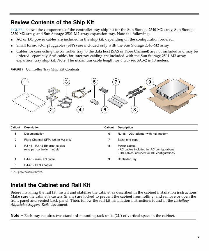
Review Contents of the Ship KitFIGURE 1 shows the components of the controller tray ship kit for the Sun Storage 2540-M2 array, Sun Storage2530-M2 array, and Sun Storage 2501-M2 array expansion tray. Note the following:
■ AC or DC power cables are included in the ship kit, depending on the configuration ordered.
■ Small form-factor pluggables (SFPs) are included only with the Sun Storage 2540-M2 array.
■ Cables for connecting the controller tray to the data host (SAS or Fibre Channel) are not included and may beordered separately. SAS cables for intertray cabling are included with the Sun Storage 2501-M2 arrayexpansion tray ship kit. Note: The maximum cable length for 6 Gb/sec SAS-2 is 10 meters.
FIGURE 1 Controller Tray Ship Kit Contents
Install the Cabinet and Rail KitBefore installing the rail kit, install and stabilize the cabinet as described in the cabinet installation instructions.Make sure the cabinet’s casters (if any) are locked to prevent the cabinet from rolling, and remove or open thefront panel and vented back panel. Then, follow the rail kit installation instructions found in the InstallingAdjustable Support Rails document.
Note – Each tray requires two standard mounting rack units (2U) of vertical space in the cabinet.
Callout Description Callout Description
1 Documentation 6 RJ-45 - DB9 adapter with null modem
2 Fibre Channel SFPs (2540-M2 only) 7 Bezel end caps
3 RJ-45 - RJ-45 Ethernet cables(one per controller module)
8 Power cables*
- AC cables included for AC configurations- DC cables included for DC configurations
* AC power cables shown.
4 RJ-45 - mini-DIN cable 9 Controller tray
5 RJ-45 - DB9 adapter
2
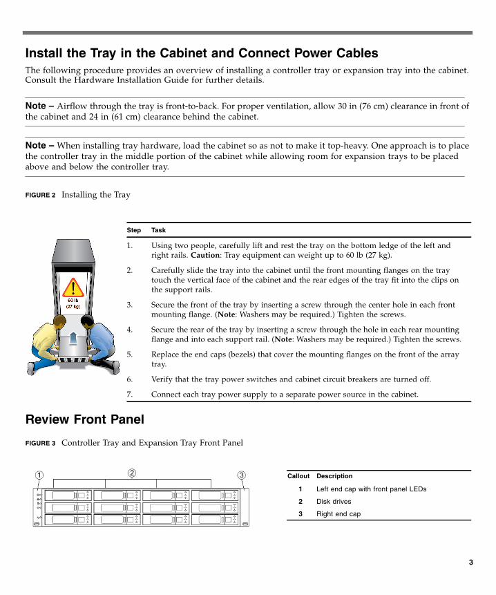
Install the Tray in the Cabinet and Connect Power CablesThe following procedure provides an overview of installing a controller tray or expansion tray into the cabinet.Consult the Hardware Installation Guide for further details.
Note – Airflow through the tray is front-to-back. For proper ventilation, allow 30 in (76 cm) clearance in front ofthe cabinet and 24 in (61 cm) clearance behind the cabinet.
Note – When installing tray hardware, load the cabinet so as not to make it top-heavy. One approach is to placethe controller tray in the middle portion of the cabinet while allowing room for expansion trays to be placedabove and below the controller tray.
FIGURE 2 Installing the Tray
Review Front Panel
FIGURE 3 Controller Tray and Expansion Tray Front Panel
Step Task
1. Using two people, carefully lift and rest the tray on the bottom ledge of the left andright rails. Caution: Tray equipment can weight up to 60 lb (27 kg).
2. Carefully slide the tray into the cabinet until the front mounting flanges on the traytouch the vertical face of the cabinet and the rear edges of the tray fit into the clips onthe support rails.
3. Secure the front of the tray by inserting a screw through the center hole in each frontmounting flange. (Note: Washers may be required.) Tighten the screws.
4. Secure the rear of the tray by inserting a screw through the hole in each rear mountingflange and into each support rail. (Note: Washers may be required.) Tighten the screws.
5. Replace the end caps (bezels) that cover the mounting flanges on the front of the arraytray.
6. Verify that the tray power switches and cabinet circuit breakers are turned off.
7. Connect each tray power supply to a separate power source in the cabinet.
Callout Description
1 Left end cap with front panel LEDs
2 Disk drives
3 Right end cap
3
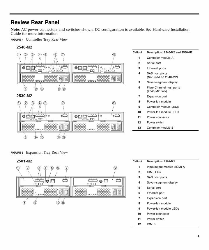
Review Rear PanelNote: AC power connectors and switches shown. DC configuration is available. See Hardware InstallationGuide for more information.
FIGURE 4 Controller Tray Rear View
FIGURE 5 Expansion Tray Rear View
Callout Description: 2540-M2 and 2530-M2
1 Controller module A
2 Serial port
3 Ethernet ports
4 SAS host ports(Not used on 2540-M2)
5 Seven-segment display
6 Fibre Channel host ports(2540-M2 only)
7 Expansion port
8 Power-fan module
9 Controller module LEDs
10 Power-fan module LEDs
11 Power connector
12 Power switch
13 Controller module B
Callout Description: 2501-M2
1 Input/output module (IOM) A
2 IOM LEDs
3 SAS host ports
4 Seven-segment display
5 Serial port
6 Ethernet port
7 Expansion port
8 Power-fan module
9 Power-fan module LEDs
10 Power connector
11 Power switch
12 IOM B
4
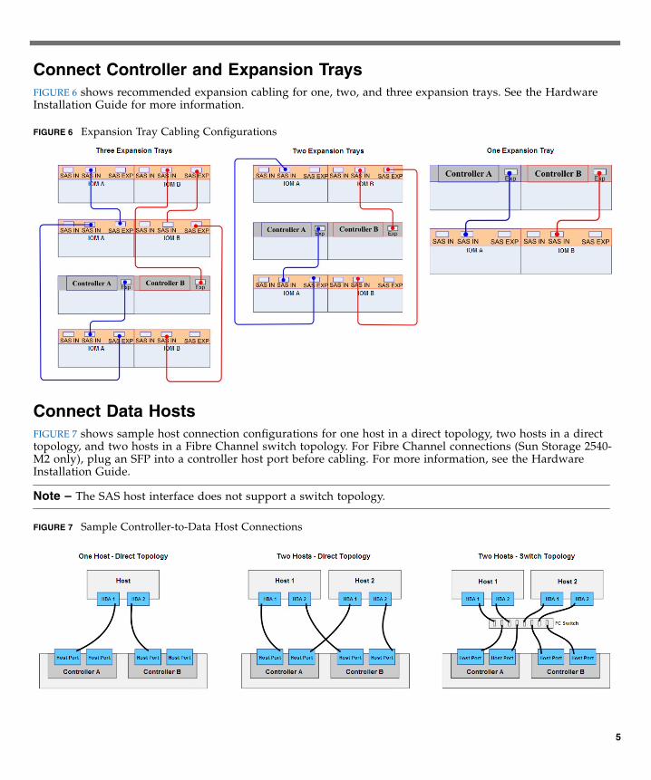
Connect Controller and Expansion TraysFIGURE 6 shows recommended expansion cabling for one, two, and three expansion trays. See the HardwareInstallation Guide for more information.
FIGURE 6 Expansion Tray Cabling Configurations
Connect Data HostsFIGURE 7 shows sample host connection configurations for one host in a direct topology, two hosts in a directtopology, and two hosts in a Fibre Channel switch topology. For Fibre Channel connections (Sun Storage 2540-M2 only), plug an SFP into a controller host port before cabling. For more information, see the HardwareInstallation Guide.
Note – The SAS host interface does not support a switch topology.
FIGURE 7 Sample Controller-to-Data Host Connections
5
Connect Management HostConnect an Ethernet cable from the management host port (Ethernet Port 1) of each controller to the LAN of themanagement host. Note: Ethernet Port 2 is reserved for access by Support personnel.
Turn on Power and Install Management Host SoftwareTo power on the array, follow the procedure in the Installation Guide. Then, install Sun Storage Common ArrayManager on the management host. If you did not previously begin the download process, see the “Sun StorageCommon Array Manager” section.
During initial array registration, you are prompted to register with the Auto Service Request (ASR) service. It ishighly recommended that you register with ASR so that Support can respond appropriately to your needs.
Documentation for This ProductAdditional documentation for Sun Storage 2500-M2 Arrays is available at:
http://www.oracle.com/technetwork/documentation/oracle-unified-ss-193371.html
Oracle Contact Information
Review safety information Sun Storage 2500-M2 Arrays Safety and Compliance Manual
Important Safety Information for Sun Hardware Systems
Review known issues and workarounds Sun Storage 2500-M2 Arrays Hardware Release Notes
Sun Storage Common Array Manager Release Notes
Prepare the site Sun Storage 2500-M2 Arrays Site Preparation Guide
Install the array Sun Storage 2500-M2 Arrays Hardware Installation Guide
Get started with the management software Sun Storage Common Array Manager Quick Start Guide
Install the management software Sun Storage Common Array Manager Installation and Setup Guide
Manage the array Sun Storage Common Array Manager Array Administration Guide
Sun Storage Common Array Manager CLI Guide
Documentation http://www.oracle.com/technetwork/indexes/documentation/index.html
Support https://support.oracle.com
Training https://education.oracle.com
Copyright © 2011, Oracle and/or its affiliates. All rights reserved.
6
Copyright © 2011, Oracle et/ou ses affiliés. Tous droits réservés.
Part No.: E20738-01Mfg No.: 7010621June 2011