Embed Size (px)
Citation preview

Summit Series SK1500 / SK2500
Control Chief Corporation 200 Williams Street, Bradford, PA 16701
814-362-6811 * 1-800-233-3016 * 814-368-4133 www.controlchief.com
Owners Manual
Failure to return the Warranty Registration document (enclosed) to Control Chief within 30 days of purchase will void any warranty
responsibilities on behalf of Control Chief Corporation
95-00-0-092 Rev 005

Control Chief Corporation, a world leader in wireless radio and infrared remote control products has, developed and expanded upon this powerful technology. More than three decades of experience in designing, manufacturing, and installing state-of-the-art remote communication systems emphasize Control Chief’s mission.
Our systems are tailored to virtually any environment or application. Control Chief provides training, technical support, and comprehensive system design to maximize performance. It is our honor to uphold this reputation of innovative engineering and superior product performance.
Publication: 95-00-0-092 Rev 005
Copyright © 2008 Control Chief Corporation
All Rights Reserved.
200 Williams Street, Bradford, Pennsylvania, 16701
Web Page: www.controlchief.com
Telephone: (814) 362-6811, FAX: (814) 368-4133

SUMMIT SERIES SK1500 / SK2500 OWNERS MANUAL
95-00-0-092 Rev 005 i Control Chief Corporation
1.0 Radio Warranty 1.1 Warranty 1.2 Warranty Period 1.3 Warranty Service 1.4 Excluded Parts 1.5 Remarks
2.0 Safety 2.1 Safety Considerations 2.2 Symbols 2.3 Warnings
3.0 Standard Components 3.1 Receiver (RX) 3.2 Transmitter (TX) 3.3 Accessories 3.3.1 Per Radio Kit 3.3.2 Per Radio Transmitter
4.0 Installation Procedure 4.1 General Precautions 4.2 Receiver Preparation 4.2.1 Installation Preparation
4.2.2 Installation Procedure 4.3 Radio Schematics 4.4 Transmitter Setup
5.0 Operation 5.1 General Precautions 5.2 Standard Operation 5.2.1 Default Power-On Procedure 5.2.2 TX Power Indication 5.3 Emergency Shutdown Procedure
6.0 Basic Troubleshooting and Maintenance 6.1 General Precautions 6.2 Transmitter Malfunction Detection 6.3 Receiver Malfunction Detection
7.0 Function Settings 7.1 Pushbutton Customization 7.2 Pushbuttons 7-12 7.3 Pushbuttons 11-12 7.4 Other Functions of the Transmitter 7.5 Other Functions of the Receiver 7.6 Downloading New Configuration Settings to Transmitter and Receiver 7.7 Remote Pairing 7.8 Manual Channel Scan
8.0 Specifications 8.1 General 8.2 Transmitter 8.3 Receiver
9.0 Appendix 9.1 Typical Receiver to Crane Interface
10.0 Mounting Template

SUMMIT SERIES SK1500 / SK2500 OWNERS MANUAL
95-00-0-092 Rev 005 1-1 Control Chief Corporation
1.0 Radio Warranty 1.1 Warranty. Control Chief Corporation guarantees that this equipment meets its published specifications at the time of
shipment from the factory. This equipment will perform as described if installed properly. However, Control Chief cannot guarantee that operation of remote control system is absolutely error-free, or without interruption. 1.2 Warranty Period. This equipment is warranted against defects in materials and workmanship for a period of one (1)
years from the date of shipment. During the warranty period, Control Chief is responsible for necessary repairs/replacement as long as the product can be proven defective. 1.3 Warranty Service. For warranty service or repair, this equipment must be returned to Control Chief Corporation.
Customer is responsible for shipping charges to Control Chief. Control Chief’s warranty covers only parts and factory labor. No onsite in and out charges are covered under this warranty. 1.4 Excluded Parts. This warranty does not include consumable parts such as joysticks, batteries, fuses, buttons, and
relays. Also, this warranty does not cover defects caused by improper installation, improper/insufficient maintenance, unauthorized modification, improper operation, ignorance of environmental specifications, and/or improper software/interfacing. 1.5 Remarks. No other warranty is expressed or implied, except for the above mentioned. The remedies provided herein
are the buyers’ sole and exclusive remedies. Control Chief shall not be liable for any direct/indirect, special, incidental, or consequential damage. Consult Control Chief’s general warranty for further information.

SUMMIT SERIES SK1500 / SK2500 OWNERS MANUAL
95-00-0-092 Rev 005 2-1 Control Chief Corporation
2.0 Safety 2.1 Safety Considerations
1. The safety guidelines in this manual are not intended to replace any rules or regulations or any applicable local, state, or federal governing laws. The following information is intended to be used in conjunction with other rules or regulations already in existence. It is important to read all safety information before operating any wireless radio remote control system.
2. Only properly trained persons designated by management should be permitted to operate wireless radio controlled equipment. Wireless radio controlled equipment should not be operated by any person who cannot read or understand signs, notices and operating instructions that pertain to the equipment.
3. Wireless radio controlled equipment should not be operated by any person with insufficient eyesight or hearing or by any person who may be suffering from a disorder or illness or is taking any medication that may impair judgment or the ability to operate equipment.
4. Do not use this device during electrical storms or under conditions of electrical interference, due to the potential for equipment communication issues. Ensure transmitter batteries are in good condition and power for receiver is correct. Installation and maintenance should be done only while the controlled equipment main power and receiver’s power are off and locked out to prevent electrical shock.
5. Any person operating wireless radio controlled equipment should possess the following knowledge and/or skills:
• Knowledge of hazards peculiar to equipment operation
• Knowledge of safety rules for radio controlled equipment
• Knowledge of standard methods of hand and/or non-verbal signaling
• Knowledge of the radio transmitter
• Limit switch test procedure
• Proper clearance of all moving parts on the radio controlled equipment
• Proper storage space for radio control transmitter when not in use
• Transferring radio control transmitter to another person
• Reporting unsafe or unusual operating conditions
• Remote controlled equipment capacity and limitations
• Procedures for testing controlled equipment
6. Aisles between equipment, stock, etc., should be free of obstructions so the radio control operator can move freely. These aisles should meet local regulations.
7. Radio operators should always position themselves for the best view of the equipment they are controlling. The equipment should never be operated blindly. The operator should always remain at a safe distance, without losing line of sight with the equipment.
8. Transmitter switches should never be mechanically blocked ON or OFF for any equipment motion. When not in use turn the transmitter OFF (RED MUSHROOM PUSHBUTTON) and remove the transmitter key.
9. After daily operation, shut off main power in crane/machine, the power to the receiver, and remove transmitter key. A secure storage space should be designated for the transmitter unit especially when not in use. This precaution is intended to prevent unauthorized use of the equipment.
10. The equipment operator should keep all body parts away from any moving parts and should never be positioned under a lifted load. Do not make a lift or move a load if anyone is in a location where they could be struck by the crane/equipment or the load.
SUMMIT SERIES SK1500 / SK2500 OWNERS MANUAL
95-00-0-092 Rev 005 2-2 Control Chief Corporation
11. If the equipment fails to respond properly, the crane/equipment operator should stop operation, turn the transmitter OFF (RED MUSHROOM PUSHBUTTON) and remove the transmitter key. The operator should immediately report the condition to his/her supervisor.
12. The crane/equipment operator should turn off the transmitter and take it with him/her when and if boarding the equipment.
13. Remote control operation should NEVER be used for “people moving” applications. Never use remote operation if there are people aboard the controlled equipment. The remote control operator should NEVER “ride” on the controlled equipment.
WARNING
ALWAYS PLACE CRANE/EQUIPMENT IN MANUAL OPERATION AND SECURE THE WIRELESS REMOTE CONTROL TRANSMITTER PRIOR TO PERFORMING ANY MAINTENANCE.
14. The equipment has been tested for correct operation before delivery from the factory. However, it must not be used in critical or hazardous operation where incorrect operation may cause personal or equipment damage. If the equipment fails to respond or behaves improperly, the equipment operator should NOT operate the equipment AND should notify his/her supervisor immediately. When serious conditions are noticed (conditions that make the crane/equipment unsafe to operate), the equipment should be shut down immediately and the supervisor notified.
CAUTION
THE RECEIVER UNIT OR RELAYS ARE NOT RATED AS EXPLOSION PROOF. THE RECEIVER UNIT MUST NOT BE INSTALLED OR OPERATED IN EXPLOSIVE ENVIRONMENTS UNLESS APPROPRIATE SECONDARY ENCLOSURE MEASURES ARE TAKEN.
WARNING
THE UNIT MUST BE WIRED TO THE CORRECT VOLTAGE; FAILURE TO DO SO MAY DAMAGE THE SYSTEM.
NOTE
IN AN EMERGENCY, PUSH “RED MUSHROOM PUSHBUTTON” TO STOP RADIO REMOTE CONTROLLED EQUIPMENT.
2.2 Symbols
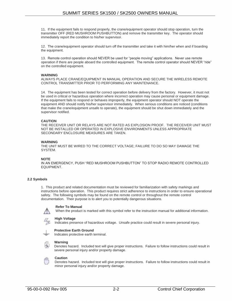
1. This product and related documentation must be reviewed for familiarization with safety markings and instructions before operation. This product requires strict adherence to instructions in order to ensure operational safety. The following symbols may be found on the remote control or throughout the remote control documentation. Their purpose is to alert you to potentially dangerous situations.
Refer To Manual
When the product is marked with this symbol refer to the instruction manual for additional information. High Voltage
Indicates presence of hazardous voltage. Unsafe practice could result in severe personal injury. Protective Earth Ground
Indicates protective earth terminal. Warning
Denotes hazard. Included text will give proper instructions. Failure to follow instructions could result in severe personal injury and/or property damage. Caution
Denotes hazard. Included text will give proper instructions. Failure to follow instructions could result in minor personal injury and/or property damage.

SUMMIT SERIES SK1500 / SK2500 OWNERS MANUAL
95-00-0-092 Rev 005 2-3 Control Chief Corporation
2.3 Warnings
1. Read this manual carefully before operating and installing this product. 2. Due to the complex nature of equipment, it is necessary to read the entire manual before installation. 3. Only authorized personnel should service this equipment. Unauthorized work on this unit will void the
warranty. 4. This manual is for reference only; please call your distributor or Control Chief if further assistance is required. 5. The equipment has been tested for correct operation before delivery from the factory. However, it must not be
used in critical or hazardous operation where incorrect operation may cause personal or equipment damage. 6. After daily operation, please shut off main power in crane/machine, the power to the receiver, and remove
transmitter key. 7. Transmitter should be placed in a safe place when not in use to avoid accidental pressing of buttons. 8. The crane/machine should be equipped with mainline contactor, limit switches, and other required safety
devices as dictated by CMAA, OSHA, or all other applicable governing regulations. 9. Do not use this device during electrical storms or under conditions of electrical interference. 10. Ensure transmitter batteries are in good condition and power for receiver is correct. 11. Installation and maintenance should be done only while the crane/machine’s main power and receiver’s
power are off and locked out to prevent electrical shock. 12. Contents of the manual may be amended by the manufacturer without notice.

SUMMIT SERIES SK1500 / SK2500 OWNERS MANUAL
95-00-0-092 Rev 005 3-1 Control Chief Corporation
3.0 Standard Components A standard and full set of SK1500/SK2500 wireless pendant consists of:
700SK3 and 700SK4 Kits include a single (1) transmitter 700DK3 and 700DK4 Kits include two (2) transmitters.
NOTE: Upon receipt of the radio kit, please identify and verify the following components are included as listed.
3.1 Receiver
SK1500 Single Speed Receiver Part Number = 701K-52539
SK2500 Two Speed Receiver Part Number = 701K-52540
3.2 Transmitter
SK1500, Single Speed Transmitter, Part Number = 701K-52530
SK2500, Two Speed Transmitter, Part Number = 701K-52531
3.3 Accessories
3.3.1 Accessories Per Radio Kit
1. Owners Manual (1 pc.) 2. 701D0023 - Spare Key (1 pc.)
3.3.2 Accessories Per Radio Transmitter
1. 0100-0230- Alkaline batteries for transmitter (6 batteries required) 2. 701K-52489 - Strap for transmitter (1 pc.) 3. 701K-52484 - Battery Holder 4. 701K-52767 - Button legend sheet for transmitter (1 pc.)

SUMMIT SERIES SK1500 / SK2500 OWNERS MANUAL
95-00-0-092 Rev 005 4-1 Control Chief Corporation
4.0 Installation Procedures 4.1 General Precautions
1. Observe all safety precautions when climbing or working on the machine. 2. Turn off the main power source of crane/machines before installation to avoid electric shock. Lockout/tagout the main power source. 3. Receiver must be installed as to not touch any part of the crane/machine or structure during the operation, except for mounting provisions. 4. The receiver must be fastened securely via shock-proof mount provided. 5. Before installation, inspect the crane/machine’s safety devices and make sure everything is in proper working condition. 6. Make sure you understand the crane/machine circuits and power distribution as well as the function setting of this remote controller, to avoid incorrect wiring. 7. To avoid any interference, the receiver must be located away from motors, frequency drives, and power cables (shown below). 8. Coil suppressors are recommended on all contactor coils and relay coils. Control Chief recommends RC type suppressors. (Control Chief part number 0700-8002)
9. The receiver should be installed on the exterior surface of the electrical control box. Mounting the receiver inside the electrical control box is not correct. An external antenna kit must be used when receiver is installed in a metal enclosure.
4.2 Receiver Preparation 4.2.1 Installation Preparation
1. Read through the following steps and procure all proper tools to complete this installation. 2. Select a proper location.
a. Select a stable place free from electrical noise, vibration, excessive heat, etc.
b. Select a place where you can see the receiver or antenna from the operator’s position.
c. Select a place where there is no interference (e.g. keep away from motors, relays, magnetic switch, and power cables).
d. Keep away from high voltage wiring and devices.
e. The Receiver’s box must be at least 1.5” (4cm) away from the other obstacles.
3. Receiver Power Supply NOTE 1: The input power source for the receiver can be
48VAC, 110VAC, 220VAC 50/60Hz (for 12/24VDC please contact Control Chief).
NOTE 2: The Factory Default is 110VAC
a. Measure your supply voltage, it must be within 10% of the selected nominal voltages; failure to do so will void the warranty.
b. Modify Power Supply Connection: After the desired power supply is confirmed, disconnect the transformer plug from the 110V connector, located in the lower left corner of the relay module board, and insert it into the correct connector on the relay module. Verify the plug is inserted correctly.
SK1500 / SK2500 Receiver
MOTOR Frequency
Converter Cable
Minimum of 3 feet separation
WARNING All / any receiver generated magnet lifting functions will be momentary in nature and cannot be maintained in the event of a power loss or fault condition. Customer MUST supply externally latching magnet circuit. The primary supply and control voltage for any external latching magnet circuit should be derived from a separately fused source. This supply should not be drawn from the receiver or any circuit controlled by the MLC (Main Line Contactor).

SUMMIT SERIES SK1500 / SK2500 OWNERS MANUAL
95-00-0-092 Rev 005 4-2 Control Chief Corporation
ON
OFF
A
OFF
ON
B
STOP
RED
MUSHROOM
PUSH BUTTON
BUTTON 1
BUTTON 3
BUTTON 5
BUTTON 7
BUTTON 11
(START)BUTTON 12
BUTTON 4
BUTTON 6
BUTTON 2
BUTTON 9 BUTTON 10
BUTTON 8
ON/OFF SWITCH A ON/OFF SWITCH B* THESE OUTPUTS ARE
ONLY AVAILABLE ON
SK2500 MODELS
NUMBER IN ( ) IS THE WIRE
NUMBER ON THE
PIGTAIL WIRE LEADS
COMING FROM THE
RECEIVER
SK1500/2500 WIRING DIAGRAM
AND
TRANSMITTER RECEIVER RELATIONSHIPMODEL:
SERIAL NO.:
(22)
(21)
(20)
(19)
(18)
(17)
(16)
(15)
(14)COM 3
COM 4
(25)
(24)
(23)
(27)
(26)
MAIN IN(3)
(2)
(1)
(4)
(5)
(6)
(7)
(8)
(9)
MAIN OUT
COM 1
AC-1
AC-2
6.3A (F3)
6.3A (F2)
DB1
DB2
0.5A (F1)
6.3A (F5)
(10)
(11)
(12)
COM 26.3A (F4)
(13) (28)COM 5
(30)
(29)SW A
SW B ROTARY KEY SWITCH
ON BOTTOM
*
*
*
*
*
*
BUTTON 1
1 SPD
BUTTON 1
2 SPD
BUTTON 2
1 SPD
BUTTON 2
2 SPD
BUTTON 3
1 SPD
BUTTON 4
1 SPD
BUTTON 3/4
2 SPD
*
BUTTON 6
1 SPD
BUTTON 5/6
2 SPD
BUTTON 5
1 SPD
BUTTON 7
1 SPD
BUTTON 8
1 SPD
BUTTON 7/8
2 SPD
BUTTON 9
1 SPD
BUTTON 10
1 SPD
BUTTON 9/10
2 SPD
BUTTON 11
1 SPD
BUTTON 12
1 SPD
BUTTON 11/12
2 SPD
4.2.2 Installation Procedure
1. Turn off the main power for crane or device.
2. Find a proper place for the receiver as detailed in the previous section.
3. Drill a hole for the 8mm stud; mount the receiver with 8mm diameter hex nut.
4. Connect wires to the control circuit of crane according to the receiver’s wiring diagram and control circuit diagram. The best place to connect the receiver is usually where the manual controls are connected to the machine controls.
5. Secure the cables between the receiver and crane so that the cable sheath will not wear out due to vibration of the crane. Check all connections. Properly terminate unused wires.
6. Turn on the main power for crane.
7. Install transmitter batteries per section 4.4 and then operate the transmitter to test every function and make sure all motions are correct (read by LED indicator).
CAUTION: When securing the cover be careful not to pinch any wires
between the case and the lid.
8. This completes the installation of receiver.
4.3 Radio Schematics
Figure 4.3
4.4 Transmitter Setup
1. Place batteries in proper direction into battery holder and insert them into the transmitter.
NOTE: It is necessary
to provide proper external
fusing on all required
commons in accordance with
the relay’s power handling
to avoid damage to the receiver and
voiding of the warranty.
SUMMIT SERIES SK1500 / SK2500 OWNERS MANUAL
95-00-0-092 Rev 005 5-1 Control Chief Corporation
5.0 Operation
NOTE: For the following procedures, the buttons on the transmitter will be referred to as noted in Figure 4.3
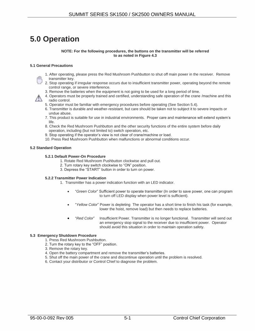
5.1 General Precautions
1. After operating, please press the Red Mushroom Pushbutton to shut off main power in the receiver. Remove
transmitter key. 2. Stop operating if irregular response occurs due to insufficient transmitter power, operating beyond the remote
control range, or severe interference. 3. Remove the batteries when the equipment is not going to be used for a long period of time. 4. Operators must be properly trained and certified, understanding safe operation of the crane /machine and this
radio control. 5. Operator must be familiar with emergency procedures before operating (See Section 5.4). 6. Transmitter is durable and weather-resistant, but care should be taken not to subject it to severe impacts or
undue abuse. 7. This product is suitable for use in industrial environments. Proper care and maintenance will extend system’s
life. 8. Check the Red Mushroom Pushbutton and the other security functions of the entire system before daily
operation, including (but not limited to) switch operation, etc. 9. Stop operating if the operator’s view is not clear of crane/machine or load. 10. Press Red Mushroom Pushbutton when malfunctions or abnormal conditions occur.
5.2 Standard Operation
5.2.1 Default Power-On Procedure
1. Rotate Red Mushroom Pushbutton clockwise and pull out. 2. Turn rotary key switch clockwise to “ON” position. 3. Depress the “START” button in order to turn on power.
5.2.2 Transmitter Power Indication
1. Transmitter has a power indication function with an LED indicator.
“Green Color” Sufficient power to operate transmitter (In order to save power, one can program to turn off LED display when power level is sufficient).
“Yellow Color” Power is depleting The operator has a short time to finish his task (for example, lower the hoist, remove load) but then needs to replace batteries.
“Red Color” Insufficient Power. Transmitter is no longer functional. Transmitter will send out an emergency stop signal to the receiver due to insufficient power. Operator should avoid this situation in order to maintain operation safety.
5.3 Emergency Shutdown Procedure
1. Press Red Mushroom Pushbutton. 2. Turn the rotary key to the “OFF” position. 3. Remove the rotary key. 4. Open the battery compartment and remove the transmitter’s batteries. 5. Shut off the main power of the crane and discontinue operation until the problem is resolved. 6. Contact your distributor or Control Chief to diagnose the problem.

SUMMIT SERIES SK1500 / SK2500 OWNERS MANUAL
95-00-0-092 Rev 005 6-1 Control Chief Corporation
6.0 Basic Troubleshooting and Maintenance 6.1 General Precautions
Daily inspection is important and will ensure safety of operation. Inspection should include testing the “Red Mushroom Pushbutton” and other safety devices and functions. If there is any doubt, operation must be stopped immediately and problems must be corrected before operation is resumed.
6.2 Transmitter Malfunction Detection
If the transmitter’s LED is rapidly flashing red, the following may have occurred: 1. Pushbutton(s) may be jammed 2. Red mushroom Pushbutton may be Depressed 3. The correct “power on” procedure may not have been properly executed.
6.3 Receiver Malfunction Detection
The receiver is equipped with simple self- diagnosing circuits and indicators. If a malfunction is detected during operation, self-diagnosing circuits will illuminate the indicators in the following sequence:
G1 R1 G2 R2 Malfunction Type
On MCU1 Fault
Blinks w/ R1 Blinks w/ RG1 DB1 / DB2 Relay Fault
Alternates w/ R1 Alternates w/ G1 Relay Driver Buffer Fault
Blinking Jammed relay
If the system is demonstrating improper operation, the following chart may help determine the cause of the malfunction:
Symptom Possible Cause
Receiver relay does not activate when associated transmitter pushbutton is depressed
1. Button may be faulty or jammed
2. Transmitter and/or receiver may be improperly coded
3. Receiver may be experiencing interference
4. Receiver may not have sufficient operating power
5. Transmitter’s Red Mushroom Pushbutton may be depressed
Intermittent operation 1. Receiver may be experiencing interference
Decreased range 1. Receiver antenna may be damaged or incorrectly installed
Transmitter does not start
1. Keyswitch may not be in the “On” position
2. Red Mushroom Pushbutton may be depressed
3. “Start” pushbutton may be defective
4. Button may be faulty or jammed

SUMMIT SERIES SK1500 / SK2500 OWNERS MANUAL
95-00-0-092 Rev 005 6-2 Control Chief Corporation
If the receiver or any of its relays fail to respond to the transmitter, the following checks may be preformed:
1 Ensure the “power on” indicator located on the front of the receiver is illuminated. If this light is off, the mainline circuit is not active.
2 Press each button on the transmitter and confirm that its associated relay’s LED is illuminated. If an LED does not illuminate, its relay is not receiving a command from the transmitter.
3 Be sure “LED 1 is illuminated. This LED is active when the “Jammed Relay Detect” circuit is working properly.
4 Be sure “LED 2” and “”LED 3” are illuminated. These LEDs are active when the receiver is getting the proper operating voltages.
5 Check fuse “F1”. This fuse is rated at .5a @ 250VAC (5x20mm) 6 Check fuses “F2-F5”. These fuses are rated at 6.3a @ 250VAC (5x20mm)

SUMMIT SERIES SK1500 / SK2500 OWNERS MANUAL
95-00-0-092 Rev 005 7-1 Control Chief Corporation
7.0 Function Settings
7.1 Pushbutton Customization
The SK1500/SK 2500 Series includes A/Off and B/Off toggle switches located at the top to the transmitter. The operation of these two toggles can be wired to operate in an A/Both/B or an A/Off/B selection mode. The A and B toggles can also either be set to respond to the EMS or to Bypass it and maintain the current state (the Default is to bypass the EMS).
The SK1500/SK 2500 radio series pushbutton programming can be altered at the factory to operate in a variety of modes. The buttons #1 and #2 can be programmed in any of the following modes:
1. Normal Momentary Operation (Default on all 12 buttons) 2. Dual Motor 1- When the pushbutton is released from 2
nd speed to the neutral position, the 1
st
speed relay is briefly activated until the button is completely released. (Only available on buttons 1&2) 3. Dual Motor 2- When the pushbutton is released from 2
nd speed to the neutral position, the 1
st speed
relay does not activate. (Only available on buttons 1&2) 4. Interlocked - All six motion groups are by default interlocked but can be NON-Interlocked.
7.2 Pushbuttons 7-12
1. On/Off: This allows the button pair to operate a single relay turning on and off.2. 2. Toggle: This mode allows each button to be alternated between an open and closed state, and maintain that
state until pressed again.
7.3 Pushbuttons 11-12
1. Inching 1: To activate, press and hold “Aux 1” (Start) button then press motion button. To deactivate,
inching function, press and release “Aux1” (Start) button again. 2. Inching 2: To activate, press and hold “Aux 1” (Start) button then press motion button. To deactivate,
release “Aux1” (Start) button
This time can be set from 0.1 to 0.5 seconds in increments of 0.1 seconds. (Not used in default)
NOTE:
Once the radio has been turned on via the START button (operating the Alarm relay) it will function the same as a normal button.
7.4 Other Functions of the Transmitter
Some of the other functions of the transmitter that can be set in software are: 1. The Transmitting mode can be set to continuous (default) or non-continuous transmit (to save power and
increase battery life). 2. An Auto Off feature is available to save power and increase battery life: Adjustable from 30 seconds to 10
minutes (default). 3. LED ON (default) or OFF (to save power and increase battery life). 4. The system channel can be programmed into the transmitter from channel 1 to 70. 5. TX Emission Power: 8 Stages are available from “Ultra High” to “Ultra Low” where as high is the default TX
power.
SUMMIT SERIES SK1500 / SK2500 OWNERS MANUAL
95-00-0-092 Rev 005 7-2 Control Chief Corporation
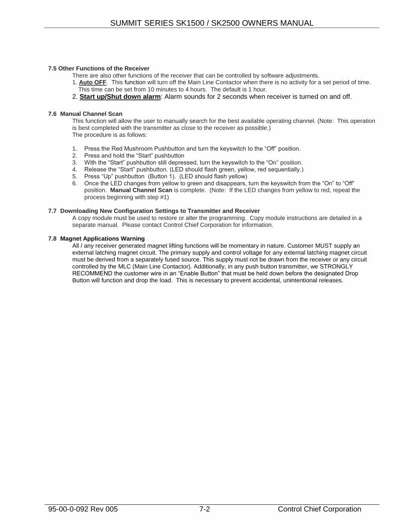
7.5 Other Functions of the Receiver
There are also other functions of the receiver that can be controlled by software adjustments. 1. Auto OFF. This function will turn off the Main Line Contactor when there is no activity for a set period of time.
This time can be set from 10 minutes to 4 hours. The default is 1 hour.
2. Start up/Shut down alarm: Alarm sounds for 2 seconds when receiver is turned on and off.
7.6 Manual Channel Scan
This function will allow the user to manually search for the best available operating channel. (Note: This operation is best completed with the transmitter as close to the receiver as possible.) The procedure is as follows: 1. Press the Red Mushroom Pushbutton and turn the keyswitch to the “Off” position. 2. Press and hold the “Start” pushbutton 3. With the “Start” pushbutton still depressed, turn the keyswitch to the “On” position. 4. Release the “Start” pushbutton. (LED should flash green, yellow, red sequentially.) 5. Press “Up” pushbutton (Button 1). (LED should flash yellow) 6. Once the LED changes from yellow to green and disappears, turn the keyswitch from the “On” to “Off”
position. Manual Channel Scan is complete. (Note: If the LED changes from yellow to red, repeat the
process beginning with step #1) 7.7 Downloading New Configuration Settings to Transmitter and Receiver
A copy module must be used to restore or alter the programming. Copy module instructions are detailed in a separate manual. Please contact Control Chief Corporation for information.
7.8 Magnet Applications Warning
All / any receiver generated magnet lifting functions will be momentary in nature. Customer MUST supply an external latching magnet circuit. The primary supply and control voltage for any external latching magnet circuit must be derived from a separately fused source. This supply must not be drawn from the receiver or any circuit controlled by the MLC (Main Line Contactor). Additionally, in any push button transmitter, we STRONGLY RECOMMEND the customer wire in an “Enable Button” that must be held down before the designated Drop Button will function and drop the load. This is necessary to prevent accidental, unintentional releases.
SUMMIT SERIES SK1500 / SK2500 OWNERS MANUAL
95-00-0-092 Rev 005 8-1 Control Chief Corporation
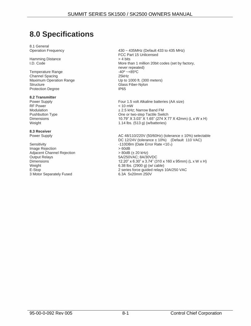
8.0 Specifications 8.1 General Operation Frequency 430 ~ 435MHz (Default 433 to 435 MHz) FCC Part 15 Unlicensed Hamming Distance > 4 bits I.D. Code More than 1 million 20bit codes (set by factory, never repeated) Temperature Range -40º ~+85ºC Channel Spacing 25kHz Maximum Operation Range Up to 1000 ft. (300 meters) Structure Glass Fiber-Nylon Protection Degree IP65 8.2 Transmitter
Power Supply Four 1.5 volt Alkaline batteries (AA size) RF Power < 10 mW Modulation ± 2.5 kHz; Narrow Band FM Pushbutton Type One or two-step Tactile Switch Dimensions 10.79” X 3.03” X 1.65” (274 X 77 X 42mm) (L x W x H) Weight 1.14 lbs. (513 g) (w/batteries) 8.3 Receiver
Power Supply AC 48/110/220V (50/60Hz) (tolerance ± 10%) selectable DC 12/24V (tolerance ± 10%) (Default 110 VAC) Sensitivity -110DBm (Date Error Rate <10-3) Image Rejection > 60dB Adjacent Channel Rejection > 80dB (± 20 kHz) Output Relays 5A/250VAC; 8A/30VDC Dimensions 12.20” x 6.30” x 3.74” (310 x 160 x 95mm) (L x W x H) Weight 6.38 lbs. (2900 g) (w/ cable) E-Stop 2 series force guided relays 10A/250 VAC 3 Motor Separately Fused 6.3A 5x20mm 250V

SUMMIT SERIES SK1500 / SK2500 OWNERS MANUAL
95-00-0-092 Rev 005 9-1 Control Chief Corporation
9.0 Appendix
9.1 Example shown of a typical Crane control with 2 speeds, 5 motors.

SUMMIT SERIES SK1500 / SK2500 OWNERS MANUAL
95-00-0-092 Rev 005 10-1 Control Chief Corporation
10.800"
3.150"
8.300"
2.890"
4.405"6.670"
.950"
.750"
6.317"1.400"
M6 (METRIC)
MOUNTING SCREW, NUT,
WASHERS AND BASE
VIBRATION
DAMPENING
RUBBER BUSHING
(4 PLACES)
120" LONG
PVC JACKET CABLE
(0.70" DIA.)
30 CONDUCTOR
16 AWG
WEIGHT: 6.39 LBS.
(WITH CABLE)
30 CONDUCTORS. 16 AWG
WITH FORK TERMINALS
20" OF LOOSE CONNECTORS
EXPOSED BEYOND PVC JACKET
10.0 Mounting Template

Installation Questions?
Technical assistance is available from Control Chief.
Please call us at 814-362-6811 or email the service department at [email protected]

Control Chief Corporation 200 Williams Street
PO Box 141 Bradford, PA 16701
814-362-6811 * 1-800-233-3016 * 814-368-4133 (fax) www.controlchief.com


![017 11/1 hinata MIYAZAKI 2017] · 2017. 11. 1. · hinata MIYAZAKI 2017] in 092-432-7612 092-262-8331 092-477-7255 092-432-5833 092-415-8118 092-432-7611 092-477-7545 092-473-0816](https://img.dokumen.tips/doc/110x75/60552fb60f45cc681a77ab1f/017-111-hinata-miyazaki-2017-2017-11-1-hinata-miyazaki-2017-in-092-432-7612.jpg)


![[Shinobi] Claymore 092](https://img.dokumen.tips/doc/110x75/568bd5b31a28ab2034996af8/shinobi-claymore-092.jpg)