Embed Size (px)
Citation preview
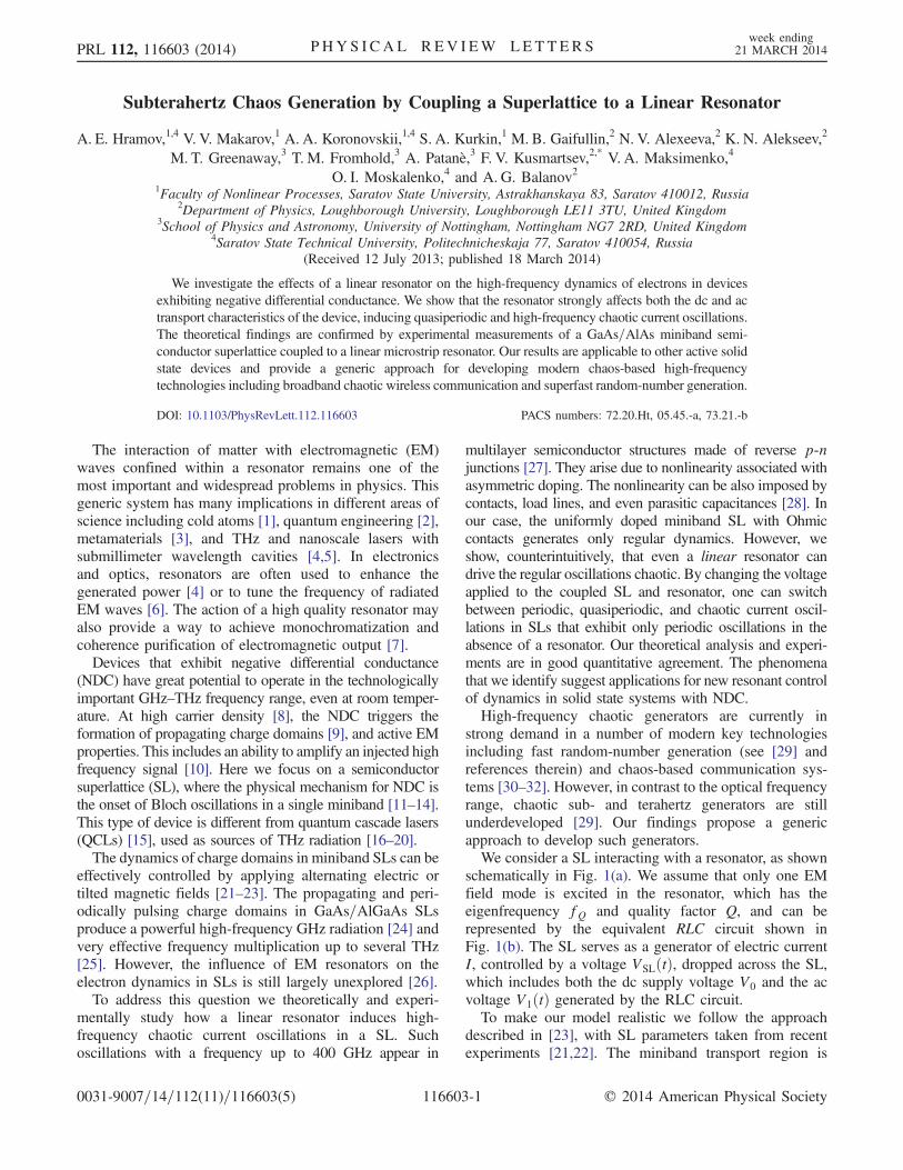
Loughborough UniversityInstitutional Repository
Subterahertz chaosgeneration by coupling asuperlattice to a linear
resonator
This item was submitted to Loughborough University's Institutional Repositoryby the/an author.
Citation: HRAMOV, A.E. ... et al, 2014. Subterahertz chaos generation bycoupling a superlattice to a linear resonator. Physical Review Letters, 112 (11),116603.
Additional Information:
• This article was published in the journal Physical Review Let-ters [ c© American Physical Society]. It is also available at:http://dx.doi.org/10.1103/PhysRevLett.112.116603
Metadata Record: https://dspace.lboro.ac.uk/2134/17299
Version: Published
Publisher: c© American Physical Society
Rights: This work is made available according to the conditions of the Cre-ative Commons Attribution-NonCommercial-NoDerivatives 4.0 International(CC BY-NC-ND 4.0) licence. Full details of this licence are available at:https://creativecommons.org/licenses/by-nc-nd/4.0/
Please cite the published version.
Subterahertz Chaos Generation by Coupling a Superlattice to a Linear Resonator
A. E. Hramov,1,4 V. V. Makarov,1 A. A. Koronovskii,1,4 S. A. Kurkin,1 M. B. Gaifullin,2 N. V. Alexeeva,2 K. N. Alekseev,2
M. T. Greenaway,3 T. M. Fromhold,3 A. Patanè,3 F. V. Kusmartsev,2,* V. A. Maksimenko,4
O. I. Moskalenko,4 and A. G. Balanov21Faculty of Nonlinear Processes, Saratov State University, Astrakhanskaya 83, Saratov 410012, Russia
2Department of Physics, Loughborough University, Loughborough LE11 3TU, United Kingdom3School of Physics and Astronomy, University of Nottingham, Nottingham NG7 2RD, United Kingdom
4Saratov State Technical University, Politechnicheskaja 77, Saratov 410054, Russia(Received 12 July 2013; published 18 March 2014)
We investigate the effects of a linear resonator on the high-frequency dynamics of electrons in devicesexhibiting negative differential conductance. We show that the resonator strongly affects both the dc and actransport characteristics of the device, inducing quasiperiodic and high-frequency chaotic current oscillations.The theoretical findings are confirmed by experimental measurements of a GaAs=AlAs miniband semi-conductor superlattice coupled to a linear microstrip resonator. Our results are applicable to other active solidstate devices and provide a generic approach for developing modern chaos-based high-frequencytechnologies including broadband chaotic wireless communication and superfast random-number generation.
DOI: 10.1103/PhysRevLett.112.116603 PACS numbers: 72.20.Ht, 05.45.-a, 73.21.-b
The interaction of matter with electromagnetic (EM)waves confined within a resonator remains one of themost important and widespread problems in physics. Thisgeneric system has many implications in different areas ofscience including cold atoms [1], quantum engineering [2],metamaterials [3], and THz and nanoscale lasers withsubmillimeter wavelength cavities [4,5]. In electronicsand optics, resonators are often used to enhance thegenerated power [4] or to tune the frequency of radiatedEM waves [6]. The action of a high quality resonator mayalso provide a way to achieve monochromatization andcoherence purification of electromagnetic output [7].Devices that exhibit negative differential conductance
(NDC) have great potential to operate in the technologicallyimportant GHz–THz frequency range, even at room temper-ature. At high carrier density [8], the NDC triggers theformation of propagating charge domains [9], and active EMproperties. This includes an ability to amplify an injected highfrequency signal [10]. Here we focus on a semiconductorsuperlattice (SL), where the physical mechanism for NDC isthe onset of Bloch oscillations in a single miniband [11–14].This type of device is different from quantum cascade lasers(QCLs) [15], used as sources of THz radiation [16–20].The dynamics of charge domains in miniband SLs can be
effectively controlled by applying alternating electric ortilted magnetic fields [21–23]. The propagating and peri-odically pulsing charge domains in GaAs=AlGaAs SLsproduce a powerful high-frequency GHz radiation [24] andvery effective frequency multiplication up to several THz[25]. However, the influence of EM resonators on theelectron dynamics in SLs is still largely unexplored [26].To address this question we theoretically and experi-
mentally study how a linear resonator induces high-frequency chaotic current oscillations in a SL. Suchoscillations with a frequency up to 400 GHz appear in
multilayer semiconductor structures made of reverse p-njunctions [27]. They arise due to nonlinearity associated withasymmetric doping. The nonlinearity can be also imposed bycontacts, load lines, and even parasitic capacitances [28]. Inour case, the uniformly doped miniband SL with Ohmiccontacts generates only regular dynamics. However, weshow, counterintuitively, that even a linear resonator candrive the regular oscillations chaotic. By changing the voltageapplied to the coupled SL and resonator, one can switchbetween periodic, quasiperiodic, and chaotic current oscil-lations in SLs that exhibit only periodic oscillations in theabsence of a resonator. Our theoretical analysis and experi-ments are in good quantitative agreement. The phenomenathat we identify suggest applications for new resonant controlof dynamics in solid state systems with NDC.High-frequency chaotic generators are currently in
strong demand in a number of modern key technologiesincluding fast random-number generation (see [29] andreferences therein) and chaos-based communication sys-tems [30–32]. However, in contrast to the optical frequencyrange, chaotic sub- and terahertz generators are stillunderdeveloped [29]. Our findings propose a genericapproach to develop such generators.We consider a SL interacting with a resonator, as shown
schematically in Fig. 1(a). We assume that only one EMfield mode is excited in the resonator, which has theeigenfrequency fQ and quality factor Q, and can berepresented by the equivalent RLC circuit shown inFig. 1(b). The SL serves as a generator of electric currentI, controlled by a voltage VSLðtÞ, dropped across the SL,which includes both the dc supply voltage V0 and the acvoltage V1ðtÞ generated by the RLC circuit.To make our model realistic we follow the approach
described in [23], with SL parameters taken from recentexperiments [21,22]. The miniband transport region is
PRL 112, 116603 (2014) P HY S I CA L R EV I EW LE T T ER Sweek ending
21 MARCH 2014
0031-9007=14=112(11)=116603(5) 116603-1 © 2014 American Physical Society
discretized into N ¼ 480 layers, each of widthδx ¼ 0.24 nm, small enough to approximate a continuumand ensure convergence of the numerical scheme. Thediscretized current continuity equation [33] is
eδxdnmdt
¼ Jm−1 − Jm; m ¼ 1;…; N; (1)
where e > 0 is the electron charge , nm is the charge densityat the right-hand edge of themth layer, at position x ¼ mδx,and Jm−1 and Jm are the areal current densities at the left-and right-hand boundaries of the mth layer
Jm ¼ enmvdðF̄mÞ; (2)
where F̄m is the mean field in the mth layer [23]. The driftvelocity, vdðF̄Þ, corresponding to the electric field, F̄, canbe calculated as in [34]:
vd ¼Δd2ℏ
I1ðΔ=2kBTÞI0ðΔ=2kBTÞ
eF̄dτ=ℏ1þ ðeF̄dτ=ℏÞ2 ; (3)
where d ¼ 8.3 nm is the period of the SL, Δ ¼ 19.1 meVis the miniband width, T ¼ 4.2 K is the temperature, kB isthe Boltzmann constant and InðxÞ, where n ¼ 0, 1, is amodified Bessel function of the first kind.The electric fields Fm and Fmþ1 at the left- and right-
hand edges of the mth layer, respectively, are related by thediscretized Poisson equation [33]
Fmþ1 ¼eδxε0εr
ðnm − nDÞ þ Fm; m ¼ 1;…; N; (4)
where ε0 and εr ¼ 12.5 are, respectively, the absolute andrelative permittivities and nD ¼ 3 × 10²² m−3 is the n-typedoping density in the SL layers [21]. The current densityinjected into the contact layers of the SL subjected tothe field F0 is J0 ¼ σF0, where σ ¼ 3788 Sm−1 is theconductivity of the heavily doped emitter [23]. The voltageVSL dropped across the SL defines a global constraint:
VSL ¼ U þ δx2
XN
m¼1
ðFm þ Fmþ1Þ; (5)
where the voltageU dropped across the contacts includes theeffect of charge accumulation and depletion in the emitter andcollector regions, and the voltage across the contact resistance[23], R ¼ 17 Ω. Finally, the current through the device is
IðtÞ ¼ AN þ 1
XN
m¼0
Jm; (6)
where A ¼ 5 × 10⁻¹⁰ m2 is the cross-sectional area of theSL [13,21,23].We apply Kirchoff’s equations to the equivalent circuit
shown in Fig. 1(b) and obtain the following equations:
dV1
dt¼ IðVSLÞ − I1
C;
dI1dt
¼ V0 − VSL þ RI1 þ RlIðVSLÞL
;
(7)
where V1ðtÞ and I1ðtÞ are, respectively, the voltageacross the capacitor and the current through the inductor[see Fig. 1(b)]. Thus, the voltage dropped across the SL isVSL ¼ V1 þ V0. The eigenfrequency of the resonator isfQ ¼1=ð2π ffiffiffiffiffiffiffi
LCp Þ and the quality factor is Q ¼ ð1=RÞ ffiffiffiffiffiffiffiffiffi
L=Cp
.The current through the SL is either constant or oscillates
depending on the voltage V0 applied to the circuit. If theSL is decoupled from the resonator (V1 ¼ 0), its current-voltage characteristic, IðVSLÞ, is of the Esaki-Tsu type [11]and the current oscillations are always periodic [23].However, if the resonator is coupled to the SL, the circuitbehavior changes greatly.In the coupled regime, the IðVSLÞ characteristic obtained
by averaging the current IðtÞ [Eq. (6)] over time is shown inFig. 2 by the dark gray (red) curve, which has a formsimilar to one discussed in [35]. In both cases there arecharge domains, whose instabilities or transformation leadto the appearance of specific features in the IðVÞ curves.However, we considerminiband transport, while inRef. [35]sequential tunneling is discussed.For low voltages, the IðV0Þ curve is Ohmic and the
current attains a maximum value when V0 ¼ Vcrit (markedby the arrow in Fig. 2). Thereafter, the current tends todecrease with increasing V0 due to the onset of Blochoscillations. However, for V0 > Vcrit there is a series ofpeaks in IðV0Þ, which do not occur in the absence ofthe resonator. These peaks correspond to the transitionsbetween the periodic and chaotic dynamical regimes. Toillustrate this, in Fig. 2 we superimpose a bifurcationdiagram in which each point shows the local maximumvalue of V1ðtÞ (RH scale) obtained for each V0 value(omitting any initial transient behavior). Thus, for a givenV0, a single point in the bifurcation diagram representseither a steady state or periodicV1ðtÞ oscillations. Similarly,several separated points indicate period-added oscillationsand a complex set of points implies either quasiperiodic orchaotic behavior. Figure 2 reveals that each peak in theIðV0Þ curve corresponds to a transition between differenttypes of dynamics in the bifurcation diagram. With
I( )VSL
Rl R
LC
-V0
V1
(a) (b)
ResonatorMicrowaves
Superlattice
I1
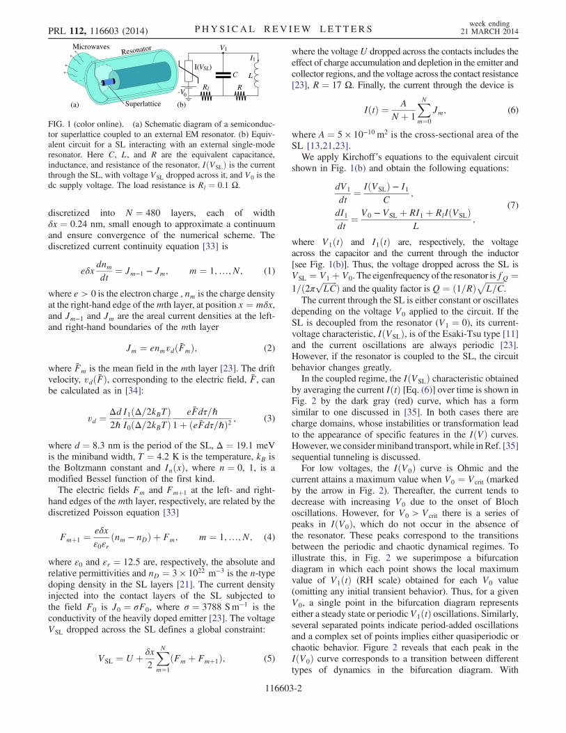
FIG. 1 (color online). (a) Schematic diagram of a semiconduc-tor superlattice coupled to an external EM resonator. (b) Equiv-alent circuit for a SL interacting with an external single-moderesonator. Here C, L, and R are the equivalent capacitance,inductance, and resistance of the resonator, IðVSLÞ is the currentthrough the SL, with voltage VSL dropped across it, and V0 is thedc supply voltage. The load resistance is Rl ¼ 0.1 Ω.
PRL 112, 116603 (2014) P HY S I CA L R EV I EW LE T T ER Sweek ending
21 MARCH 2014
116603-2
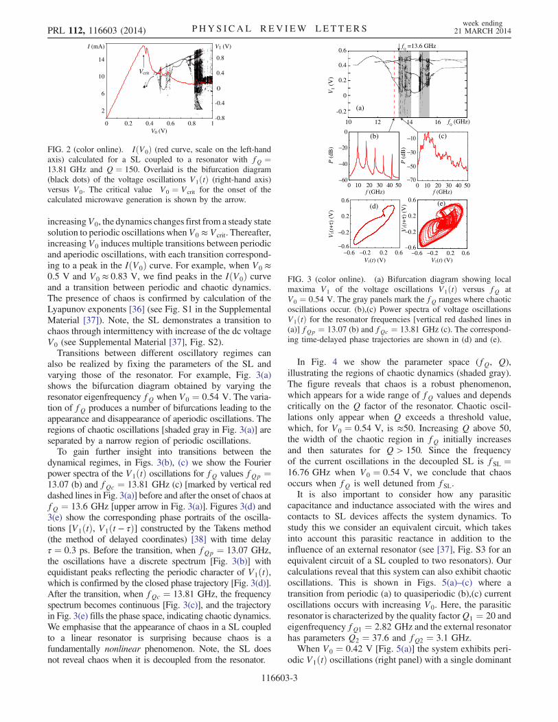
increasingV0, the dynamics changes first from a steady statesolution to periodic oscillations whenV0 ≈ Vcrit. Thereafter,increasing V0 induces multiple transitions between periodicand aperiodic oscillations, with each transition correspond-ing to a peak in the IðV0Þ curve. For example, when V0 ≈0.5 V and V0 ≈ 0.83 V, we find peaks in the IðV0Þ curveand a transition between periodic and chaotic dynamics.The presence of chaos is confirmed by calculation of theLyapunov exponents [36] (see Fig. S1 in the SupplementalMaterial [37]). Note, the SL demonstrates a transition tochaos through intermittency with increase of the dc voltageV0 (see Supplemental Material [37], Fig. S2).Transitions between different oscillatory regimes can
also be realized by fixing the parameters of the SL andvarying those of the resonator. For example, Fig. 3(a)shows the bifurcation diagram obtained by varying theresonator eigenfrequency fQ when V0 ¼ 0.54 V. The varia-tion of fQ produces a number of bifurcations leading to theappearance and disappearance of aperiodic oscillations. Theregions of chaotic oscillations [shaded gray in Fig. 3(a)] areseparated by a narrow region of periodic oscillations.To gain further insight into transitions between the
dynamical regimes, in Figs. 3(b), (c) we show the Fourierpower spectra of the V1ðtÞ oscillations for fQ values fQp ¼13.07 (b) and fQc ¼ 13.81 GHz (c) [marked by vertical reddashed lines in Fig. 3(a)] before and after the onset of chaos atfQ ¼ 13.6 GHz [upper arrow in Fig. 3(a)]. Figures 3(d) and3(e) show the corresponding phase portraits of the oscilla-tions [V1ðtÞ, V1ðt − τÞ] constructed by the Takens method(the method of delayed coordinates) [38] with time delayτ ¼ 0.3 ps. Before the transition, when fQp ¼ 13.07 GHz,the oscillations have a discrete spectrum [Fig. 3(b)] withequidistant peaks reflecting the periodic character of V1ðtÞ,which is confirmed by the closed phase trajectory [Fig. 3(d)].After the transition, when fQc ¼ 13.81 GHz, the frequencyspectrum becomes continuous [Fig. 3(c)], and the trajectoryin Fig. 3(e) fills the phase space, indicating chaotic dynamics.We emphasise that the appearance of chaos in a SL coupledto a linear resonator is surprising because chaos is afundamentally nonlinear phenomenon. Note, the SL doesnot reveal chaos when it is decoupled from the resonator.
In Fig. 4 we show the parameter space (fQ, Q),illustrating the regions of chaotic dynamics (shaded gray).The figure reveals that chaos is a robust phenomenon,which appears for a wide range of fQ values and dependscritically on the Q factor of the resonator. Chaotic oscil-lations only appear when Q exceeds a threshold value,which, for V0 ¼ 0.54 V, is ≈50. Increasing Q above 50,the width of the chaotic region in fQ initially increasesand then saturates for Q > 150. Since the frequencyof the current oscillations in the decoupled SL is fSL ¼16.76 GHz when V0 ¼ 0.54 V, we conclude that chaosoccurs when fQ is well detuned from fSL.It is also important to consider how any parasitic
capacitance and inductance associated with the wires andcontacts to SL devices affects the system dynamics. Tostudy this we consider an equivalent circuit, which takesinto account this parasitic reactance in addition to theinfluence of an external resonator (see [37], Fig. S3 for anequivalent circuit of a SL coupled to two resonators). Ourcalculations reveal that this system can also exhibit chaoticoscillations. This is shown in Figs. 5(a)–(c) where atransition from periodic (a) to quasiperiodic (b),(c) currentoscillations occurs with increasing V0. Here, the parasiticresonator is characterized by the quality factorQ1 ¼ 20 andeigenfrequency fQ1 ¼ 2.82 GHz and the external resonatorhas parameters Q2 ¼ 37.6 and fQ2 ¼ 3.1 GHz.When V0 ¼ 0.42 V [Fig. 5(a)] the system exhibits peri-
odic V1ðtÞ oscillations (right panel) with a single dominant
-0.8
-0.4
0
0.4
0.8
0 0.2 0.4 0.6 0.8 1
2
6
10
14
I (mA)
V0 (V)
V1 (V)
Vcrit
FIG. 2 (color online). IðV0Þ (red curve, scale on the left-handaxis) calculated for a SL coupled to a resonator with fQ ¼13.81 GHz and Q ¼ 150. Overlaid is the bifurcation diagram(black dots) of the voltage oscillations V1ðtÞ (right-hand axis)versus V0. The critical value V0 ¼ Vcrit for the onset of thecalculated microwave generation is shown by the arrow.
-0.2
0
0.2
0.4
0.6
12 14 16 fQ (GHz)
V1
(V)
10
fQ =13.6 GHz
0 10 20 30 40 50
−0.6
−0.2
0.2
0.6
−0.2 0.2 0.6−0.6
−0.2
0.2
0.6
(b)
0 10 20 30 40 50
−0.6 −0.2 0.2 0.6
P (
dB)
P (
dB)
f (GHz)
−0.6
−60
−40
−20
−70
−50
−30
−10
V1(t) (V)
V1(
t+τ)
(V
)
V1(
t+τ)
(V
)
0(c)
(d) (e)
V1(t) (V)
f (GHz)
(a)
FIG. 3 (color online). (a) Bifurcation diagram showing localmaxima V1 of the voltage oscillations V1ðtÞ versus fQ atV0 ¼ 0.54 V. The gray panels mark the fQ ranges where chaoticoscillations occur. (b),(c) Power spectra of voltage oscillationsV1ðtÞ for the resonator frequencies [vertical red dashed lines in(a)] fQp ¼ 13.07 (b) and fQc ¼ 13.81 GHz (c). The correspond-ing time-delayed phase trajectories are shown in (d) and (e).
PRL 112, 116603 (2014) P HY S I CA L R EV I EW LE T T ER Sweek ending
21 MARCH 2014
116603-3
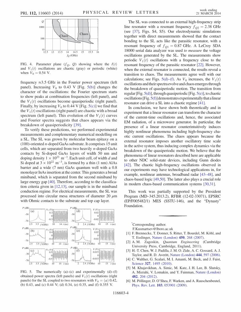
frequency ≈3.5 GHz in the Fourier power spectrum (leftpanel). Increasing V0 to 0.43 V [Fig. 5(b)] changes thecharacter of the oscillations: the Fourier spectrum startsto show peaks at combination frequencies (left panel), andthe V1ðtÞ oscillations become quasiperiodic (right panel).Finally, by increasing V0 to 0.44 V [Fig. 5(c)] we find thatthe V1ðtÞ oscillations (right panel) are chaotic with a broadspectrum (left panel). This evolution of the V1ðtÞ curvesand Fourier spectra suggests that chaos appears via thebreakdown of quasiperiodicity [39].To verify these predictions, we performed experimental
measurements and complementary numerical modelling ona SL. The SL was grown by molecular beam epitaxy on a(100)-oriented n-dopedGaAs substrate. It comprises 15 unitcells, which are separated from two heavily n-doped GaAscontacts by Si-doped GaAs layers of width 50 nm anddoping density 1 × 10²³ m−3. Each unit cell, of width d andSi doped at 3 × 10²² m−3, is formed by a thin (1 nm) AlAsbarrier and a wide (7 nm) GaAs quantum well with a 0.8monolayer InAs insertion at the center. This generates a broadminiband, which is separated from the second miniband bylarge energy gap [40]. Therefore, according to the classifica-tion criteria given in [12,13], our sample is in the minibandconduction regime. For electrical measurements, the SL wasprocessed into circular mesa structures of diameter 20 μmwith Ohmic contacts to the substrate and top cap layer.
The SL was connected to an external high-frequency stripline resonator with a resonant frequency fQ2 ¼ 2.38 GHz(see [37], Figs. S4, S5). Our electrodynamic simulationstogether with direct measurements showed that the contactbonding to the SL acts like the parasitic resonator, with aresonant frequency of fQ1 ¼ 0.87 GHz. A LeCroy SDA18000 serial data analyzer was used to measure the voltageoscillations generated by the SL. The measurements showperiodic V1ðtÞ oscillations with a frequency close to theresonant frequency of the parasitic resonator [22]. However,when the external resonator is connected, the results reveal atransition to chaos. The measurements agree well with ourcalculations; see Figs. 5(d)–(f). As V0 increases, the V1ðtÞoscillationsandtheir spectraevolveandchaosemerges throughthe breakdown of quasiperiodic motion. The transition fromregular [Fig. 5(d)], throughquasiperiodic [Fig. 5(e)], to chaoticoscillations[Fig.5(f)]demonstratesexperimentallythatalinearresonator can drive a SL into a chaotic regime [41].In conclusion, we have shown both theoretically and in
experiment that a linear resonator can transform the characterof the current-time oscillations and, hence, the associatedEM radiation, of a microwave generator. In particular, thepresence of a linear resonator counterintuitively induceshighly nonlinear phenomena including high-frequency cha-otic current oscillations. The chaos appears because theexternal resonator imposes another oscillatory time scalein the active system, thus inducing complex dynamics via thebreakdown of the quasiperiodic motion. We believe that thephenomena of linear resonators described here are applicableto other NDC solid-state devices, including Gunn diodes[42]. The chaotic high-frequency oscillations observed inour experiments may have technological applications in, forexample, nonlinear antennas, broadband radar [43–48], andchaos-based logic [49,50]. The latter also plays a crucial rolein modern chaos-based communication systems [30,31].
This work was partially supported by the PresidentProgram (MD–345.2013.2), RFBR (12-02-33071), EPSRC(EP/F005482/1) MES (SSTU-146), and the “Dynasty”Foundation.
*Corresponding [email protected]
[1] F. Brennecke, T. Donner, S. Ritter, T. Bourdel, M. Köhl, andT. Esslinger, Nature (London) 450, 268 (2007).
[2] A. M. Zagoskin, Quantum Engineering (CambridgeUniversity Press, Cambridge, England, 2011).
[3] H.-T. Chen, W. J. Padilla, J. M. O. Zide, A. C. Gossard, A. J.Taylor, and R. D. Averitt, Nature (London) 444, 597 (2006).
[4] C. Walther, G. Scalari, M. I. Amanti, M. Beck, and J. Faist,Science 327, 1495 (2010).
[5] M. Khajavikhan, A. Simic, M. Katz, J. H. Lee, B. Slutsky,A. Mizrahi, V. Lomakin, and Y. Fainman, Nature (London)482, 204 (2012).
[6] M. Pöllinger, D. O’Shea, F. Warken, and A. Rauschenbeutel,Phys. Rev. Lett. 103, 053901 (2009).
10
100
1000
12.5 13 13.5 14 14.5 15 15.5 16
Q
fQ (GHz)
ChaosChaos
FIG. 4. Parameter plane (fQ, Q) showing where the IðtÞand V1ðtÞ oscillations are chaotic (gray) or periodic (white)when V0 ¼ 0.54 V.
f (GHz) 10 2 2.4-70
-30
P (dB)
15 t (ns)
V (V)(a)
-70
-30
P (dB)
(b)
-70
-30
P (dB)(c)
-0.020
0.02
f (GHz) 2 2.4
f (GHz) 2 2.4
10 15 t (ns)
V (V)
-0.020
0.02
10 15 t (ns)
V (V)
-0.0150
0.015
2.5 f (GHz) 10 3.5-70
-30
P (dB)
14 t (ns)
V1 (V) (d)
2.5 f (GHz) 10 3.5-70
-30
P (dB)
14 t (ns)
-0.40
0.4V1 (V) (e)
2.5 f (GHz) 10 3.5-70
-30
P (dB)
14 t (ns)
V1 (V) (f)
-0.30
0.3
-0.50
0.5
FIG. 5. The numerically (a)–(c) and experimentally (d)–(f)obtained power spectra (left panels) and V1ðtÞ oscillations (rightpanels) for the SL coupled to two resonators with V0 ¼ ðaÞ 0.42,(b) 0.43, and (c) 0.44 V; (d) 0.34, (e) 0.35, and (f) 0.355 V.
PRL 112, 116603 (2014) P HY S I CA L R EV I EW LE T T ER Sweek ending
21 MARCH 2014
116603-4

[7] X. R. Huang, D. P. Siddons, A. T. Macrander, R. W. Peng,and X. S. Wu, Phys. Rev. Lett. 108, 224801 (2012).
[8] H. Kroemer, Proc. IEEE 52, 1736 (1964).[9] J. B. Gunn, IBM J. Res. Dev. 8, 141 (1964).
[10] H.W.Thim, IEEETrans.ElectronDevices14, 517 (1967); I. V.Altukhov, M. S. Kagan, S. G. Kalashnikov, V. V. Kukushkin,and S.M. Ovechkin, Sov. Tech. Phys. Lett. 6, 237 (1980).
[11] L. Esaki and R. Tsu, IBM J. Res. Dev. 14, 61 (1970).[12] Andreas Wacker and Antti-Pekka Jauho, Phys. Rev. Lett.
80, 369 (1998).[13] A. Wacker, Phys. Rep. 357, 1 (2002).[14] F. Klappenberger, K. N. Alekseev, K. F. Renk, R. Scheuerer, E.
Schomburg, S. J. Allen, G. R. Ramian, S. S. Scott, A. Kovsh,V. Ustinov, and A. Zhukov, Eur. Phys. J. B 39, 483 (2004);A. A.IgnatovandV. I.Shashkin,Sov.Phys.JETP66,526(1987).
[15] Note that active EM properties of the single miniband SLsare distinctly different from QCLs, whose generationinvolves a population inversion [16–18]. Usually QCLsare engineered to avoid NDC [16]. They are routinely ableto generate EM emission within the frequency range frommidinfrared to around one THz [19]. However, for lasing inthe sub-THz range QSLs require a low temperature [19] anda very strong magnetic field [20].
[16] J. Faist, F. Capasso, D. L. Sivco, C. Sirtori, A. L.Hutchinson, and A. Y. Cho, Science 264, 553 (1994).
[17] R. Köhler, A. Tredicucci, F. Beltram, H. E. Beere, E. H.Linfield, A. Giles Davies, D. A. Ritchie, R. C. Iotti, and F.Rossi, Nature (London) 417, 156 (2002).
[18] T. Schmielau and M. F. Pereira, Jr, Appl. Phys. Lett. 95,231111 (2009).
[19] G. Scalari, C. Walther, M. Fischer, R. Terazzi, H. Beere, D.Ritchie, and J. Faist, Laser Photonics Rev. 3, 45 (2009).
[20] A.Wade, G. Fedorov, D. Smirnov, S. Kumar, B. S.Williams,Q. Hu, and J. L. Reno, Nat. Photonics 3, 41 (2009).
[21] T. M. Fromhold et al., Nature (London) 428, 726 (2004).[22] N. Alexeeva, M. T. Greenaway, A. G. Balanov, O.
Makarovsky, A. Patanè, M. B. Gaifullin, F. Kusmartsev,and T. M. Fromhold, Phys. Rev. Lett. 109, 024102 (2012).
[23] M. T. Greenaway, A. G. Balanov, E. Scholl, and T. M.Fromhold, Phys. Rev. B 80, 205318 (2009).
[24] K. Hofbeck et al., Phys. Lett. A 218, 349 (1996); H. Eisele,S. P. Khanna, and E. H. Linfield, Appl. Phys. Lett. 96,072101 (2010).
[25] C. P. Endres, F. Lewen, T. F. Giesen, S. Schlemmer, D. G.Paveliev, Y. I. Koschurinov, V. M. Ustinov, and A. E. Zhucov,Rev. Sci. Instrum. 78, 043106 (2007); P. Khosropanah,A. Baryshev, W. Zhang, W. Jellema, J. N. Hovenier, J. R.Gao,T.M.Klapwijk,D. G. Paveliev,B. S.Williams, S.Kumar,Q.Hu, J. L.Reno,B.Klein, and J. L.Hesler,Opt. Lett.34, 2958(2009); D. G. Paveliev, Y. I. Koshurinov, A. S. Ivanov, A. N.Panin, V. L. Vax, V. I. Gavrilenko, A. V. Antonov, V.M.Ustinov, and A. E. Zhukov, Semiconductors 46, 121 (2012).
[26] K. F. Renk, B. Stahl, A. Rogl, T. Janzen, D. Pavel’ev, Yu.Koshurinov, V. Ustinov, and A. Zhukov, Phys. Rev. Lett. 95,126801 (2005); A. A. Ignatov, Semicond. Sci. Technol. 26,055015 (2011).
[27] K. A. Lukin, H. A. Cerdeira, and A. A. Colavita, Appl.Phys. Lett. 71, 2484 (1997); K. A. Lukin, H. A. Cerdeira,and P. P. Maximov, ibid. 83, 4643 (2003).
[28] E. Schöll, Nonlinear Spatio-Temporal Dynamics andChaos in Semiconductors (Cambridge University Press,Cambridge, England, 2001).
[29] W. Li, I. Reidler, Y. Aviad, Y. Huang, H. Song, Y. Zhang, M.Rosenbluh, and I. Kanter, Phys. Rev. Lett. 111, 044102 (2013).
[30] Special Issue on Applications of Nonlinear Dynamics toElectronic and Information Engineering, edited by M.Hasler et al. [Proc. IEEE. 90, 5 (2002)].
[31] F. C. M. Lau and C. K. Tse, Chaos-Based Digital Commu-nication Systems: Operating Principles, Analysis Methods,and Performance Evaluation (Springer, New York, 2003).
[32] H.-P. Ren, M. S. Baptista, and C. Grebogi, Phys. Rev. Lett.110, 184101 (2013).
[33] To calculate the charge dynamics in the SL, and thus obtainthe current-voltage IðVSLÞ characteristics, we numericallysolve the discrete current continuity and Poisson equations.
[34] Yu. A. Romanov, Opt. Spectrosc. 33, 917 (1972).[35] B. J. Keay, S. Zeuner, S. Allen, K. Maranowski, A. Gossard,
U. Bhattacharya, and M. Rodwell, Phys. Rev. Lett. 75, 4102(1995).
[36] A. A. Koronovskii, A. E. Hramov, V. A. Maximenko, O. I.Moskalenko, K. N. Alekseev, M. T. Greenaway, T.M. From-hold, and A. G. Balanov, Phys. Rev. B 88, 165304 (2013).
[37] See Supplemental Material at http://link.aps.org/supplemental/10.1103/PhysRevLett.112.116603 for theLyapunov analysis, the equivalent circuit of a SL coupledto two resonators, our experimental setup of the SL withexternal microstrip resonator, the results of our electrody-namic calculations of the mode parameters of the microstripresonator, and illustrations of the transition from periodic tochaotic dynamics in the SL system.
[38] F. Takens, Lectures Notes in Mathematics (Springer-Verlag,Berlin, 1981), p. 366.
[39] V. S. Anishchenko, Dynamical Chaos—Models and Experi-ments. Appearance Routes and Structure of Chaos in SimpleDynamical Systems (World Scientific, Singapore, 1995).
[40] A. Patanè,D. Sherwood,L. Eaves, T.M. Fromhold,M.Henini,P. C. Main, and G. Hill, Appl. Phys. Lett. 81, 661 (2002).
[41] The resonator imposes a new oscillatory time scale in thesystem, thus inducing quasiperiodic current oscillations.Under certain conditions, when the nonlinear mixing [e.g.,by nonlinearity in vdðFÞ dependence] of oscillations withdifferent time scales is strong enough, the quasiperiodicmotion loses its stability [39], which leads to the appearanceof chaos in the system (see also [37], Fig. S6).
[42] I. V. Altukhov, M. S. Kagan, S. G. Kalashnikov, and V. V.Kukushkin, Sov. Tech. Phys. Lett. 2, 186 (1976); Sov. Phys.Semicond. 13, 1148 (1979).
[43] A. A. Koronovskii, O. I Moskalenko, and A. E Hramov,Phys. Usp. 52, 1213 (2009).
[44] G. S. Nusinovich, A. N. Vlasov, and T. M. Antonsen, Phys.Rev. Lett. 87, 218301 (2001).
[45] V. Dronov, M. R. Hendrey, T. M. Antonsen, and E. Ott,Chaos 14, 30 (2004).
[46] Yu. A. Kalinin, A. A. Koronovskii, A. E. Khramov, E. N.Egorov, and R. A. Filatov, Plasma Phys. Rep. 31, 938 (2005).
[47] B. S. Dmitriev, A. Hramov, A. Koronovskii, A. Starodubov,D. Trubetskov, and Y. Zharkov, Phys. Rev. Lett. 102,074101 (2009).
[48] R. A. Filatov, A. E. Hramov, Y. P. Bliokh, A. A. Koronov-skii, and J. Felsteiner, Phys. Plasmas 16, 033106 (2009).
[49] S. Sinha, and W. L. Ditto, Phys. Rev. Lett. 81, 2156 (1998).[50] B. Kia, A. Dari, W. L. Ditto, and M. L. Spano, Chaos 21,
047520 (2011).
PRL 112, 116603 (2014) P HY S I CA L R EV I EW LE T T ER Sweek ending
21 MARCH 2014
116603-5