Embed Size (px)
Citation preview

Review of terahertz and subterahertz wireless communicationsJohn Federici and Lothar Moeller Citation: Journal of Applied Physics 107, 111101 (2010); doi: 10.1063/1.3386413 View online: http://dx.doi.org/10.1063/1.3386413 View Table of Contents: http://scitation.aip.org/content/aip/journal/jap/107/11?ver=pdfcov Published by the AIP Publishing Articles you may be interested in Sub-terahertz microsecond optically controlled switch with GaAs active element beyond the photoelectricthreshold Rev. Sci. Instrum. 87, 014704 (2016); 10.1063/1.4939673 Probing a dielectric resonator acting as passive sensor through a wireless microwave link Rev. Sci. Instrum. 85, 094704 (2014); 10.1063/1.4894264 Remote vibration measurement: A wireless passive surface acoustic wave resonator fast probing strategy Rev. Sci. Instrum. 83, 055001 (2012); 10.1063/1.4705728 Detecting optically synthesized quasi-monochromatic sub-terahertz phonon wavepackets by ultrafast x-raydiffraction Appl. Phys. Lett. 100, 094101 (2012); 10.1063/1.3688492 Terahertz antenna based on graphene J. Appl. Phys. 107, 104313 (2010); 10.1063/1.3427536
Reuse of AIP Publishing content is subject to the terms at: https://publishing.aip.org/authors/rights-and-permissions. Download to IP: 128.187.112.19 On: Tue, 12 Apr 2016
19:06:31
APPLIED PHYSICS REVIEWS—FOCUSED REVIEW
Review of terahertz and subterahertz wireless communicationsJohn Federici1,a� and Lothar Moeller2,b�
1Department of Physics, New Jersey Institute of Technology, Newark, New Jersey, 07102 USA2Bell Labs, Alcatel-Lucent, Holmdel, New Jersey 07733, USA
�Received 4 November 2009; accepted 9 March 2010; published online 9 June 2010�
According to Edholm’s law, the demand for point-to-point bandwidth in wireless short-rangecommunications has doubled every 18 months over the last 25 years. It can be predicted that datarates of around 5–10 Gb/s will be required in ten years. In order to achieve 10 Gb/s data rates, thecarrier frequencies need to be increased beyond 100 GHz. Over the past ten years, several groupshave considered the prospects of using sub-terahertz �THz� and THz waves �100–2000 GHz� as ameans to transmit data wirelessly. Some of the reported advantages of THz communications linksare inherently higher bandwidth compared to millimeter wave links, less susceptibility toscintillation effects than infrared wireless links, and the ability to use THz links for securecommunications. Our goal of this paper is to provide a comprehensive review of wireless sub-THzand THz communications. © 2010 American Institute of Physics. �doi:10.1063/1.3386413�
TABLE OF CONTENTS
I. OVERVIEW OF REVIEW: ADVANTAGES OFTERAHERTZ COMMUNICATION SYSTEMS. . . . 1
II. THZ AND SUB-THZ COMMUNICATIONS:BASIC CONSIDERATIONS. . . . . . . . . . . . . . . . . . . 3
A. Free space propagation versus guided THzwaves. . . . . . . . . . . . . . . . . . . . . . . . . . . . . . . . . 3
B. Directionality of THz radiation. . . . . . . . . . . . 4C. Scintillation. . . . . . . . . . . . . . . . . . . . . . . . . . . . 4D. Atmospheric and free-space damping
including fog, rain, and snow. . . . . . . . . . . . . 5E. Indoor versus outdoor. . . . . . . . . . . . . . . . . . . . 7
III. SECURE WIRELESS THZCOMMUNICATIONS. . . . . . . . . . . . . . . . . . . . . . . 9
IV. THZ HARDWARE FOR WIRELESSCOMMUNICATIONS. . . . . . . . . . . . . . . . . . . . . . . 11
A. Methods of THz generation. . . . . . . . . . . . . . . 111. Optoelectronic. . . . . . . . . . . . . . . . . . . . . . . 112. Microwave frequency multipliers. . . . . . . . 133. Quantum cascade lasers. . . . . . . . . . . . . . . . 13
B. Methods of THz detection forcommunication links. . . . . . . . . . . . . . . . . . . . . 13
C. THz antennas. . . . . . . . . . . . . . . . . . . . . . . . . . 14V. IMPLEMENTATION OF THZ
COMMUNICATION. . . . . . . . . . . . . . . . . . . . . . . . . 15A. THz generator specific modulation schemes.. 15
1. Optoelectronic systems. . . . . . . . . . . . . . . . 152. Schottky diode mixer systems. . . . . . . . . . . 15
B. THz generator independent modulationschemes. . . . . . . . . . . . . . . . . . . . . . . . . . . . . . . 16
C. Clock recovery. . . . . . . . . . . . . . . . . . . . . . . . . 17VI. THZ AND SUB-THZ COMMUNICATION
SYSTEMS. . . . . . . . . . . . . . . . . . . . . . . . . . . . . . . . . 17A. Optoelectonic systems. . . . . . . . . . . . . . . . . . . 17
1. Time-domain systems. . . . . . . . . . . . . . . . . 172. Photonic MMW/UTC-PD optoelectronic
systems. . . . . . . . . . . . . . . . . . . . . . . . . . . . . 19B. Integrated circuit systems. . . . . . . . . . . . . . . . . 20C. Microwave multiplier systems. . . . . . . . . . . . . 20
VII. SUMMARY AND CONCLUSIONS. . . . . . . . . . . 20
I. OVERVIEW OF REVIEW: ADVANTAGES OFTERAHERTZ COMMUNICATION SYSTEMS
The field of terahertz �THz� spectroscopy, imaging, andtechnology has grown dramatically over the past fifteenyears.1 In conjunction with new and improved THz sourcesand detectors,2–7 THz spectrometers and imaging systems8
have become routine laboratory instruments and have foundseveral niche and industrial applications including explosiveand concealed weapon detection,9–12 pharmaceutical qualitycontrol,13 biology/medicine,14 and nondestructive evaluation/quality control.15–17 Over the past ten years, several groupshave considered the prospects of using THz waves as ameans to transmit data. Numerous papers covering variousaspects of the topic—THz sources and detectors, modulationschemes, wireless communication measurements—havebeen reported in the literature. We comprehensively reviewapproaches to wireless THz communication.
In the literature, there are various definitions of the THzfrequency range. For the purposes of this paper, we shalldefine the sub-THz region as covering 0.1–0.3 THz and theTHz region as covering 0.3–10 THz. For the sake of brevityin the paper, we shall use the term “THz” to generically referto the 0.1–10 THz range, unless otherwise specified. Data
a�Electronic mail: [email protected]. Phone: 973-596-8482.b�Electronic mail: [email protected]. Phone: 732-888-7237.
JOURNAL OF APPLIED PHYSICS 107, 111101 �2010�
0021-8979/2010/107�11�/111101/22/$30.00 © 2010 American Institute of Physics107, 111101-1
Reuse of AIP Publishing content is subject to the terms at: https://publishing.aip.org/authors/rights-and-permissions. Download to IP: 128.187.112.19 On: Tue, 12 Apr 2016
19:06:31

communication systems that operate, for example, at 94 GHzand below will not be covered by this review unless theydirectly related to data communications in the sub-THz orTHz range. We further limit the review of the field to includeTHz waves as the free-space carrier of data.
Commercial wireless point-to-point microwave commu-nications systems currently operate at carrier frequencies ashigh as 18 to 30 GHz �K band and Ka band�. Several re-search projects in the fields of electronics and fiber opticshave focused in the past on developing devices for commu-nication system running at 60 GHz signals. The high oxygenabsorption peak in this frequency bands strongly attenuatesradio signals allowing the design of low interference picocellmobile communication systems with ultrahigh capacity.18,19
Even at higher frequencies up to 300 GHz the Federal Com-munications Commission �FCC� has started to allocate fre-quency bands for mobile, satellite, and wireless links.20
Historically, individual �point-to-point� and aggregated�within a volume of space� bandwidth demands for wirelessnetworking have increased rapidly over the last two decades.One way of meeting these bandwidth demands is to increasethe spectral utilization efficiency by applying advancedmodulation techniques, which enable increased point-to-point data rates, enhanced sharing of a given band of fre-quencies, and higher amounts of frequency reuse within avolume of space. However, Shannon’s channel capacity for-mula, even when extended to wireless networking in ashared volume of space through the use of multi-input/multioutput approaches, shows an upper limit for this strat-egy. Beyond this point transmission bands at higher carrierfrequencies have to be accessed to provide sufficient trans-mission capacity. According to Edholm’s law ofbandwidth,21 the demand for bandwidth in wireless short-range communications has doubled every 18 months over thelast 25 years. �e.g., from less than 1 kb/s for wireless telem-etry in 1984 to more than 100 Mb/s with 802.11n wirelesslocal area networks in 2009.� From this recent trend, it canbe predicted that data rates of around 5–10 Gb/s will berequired in ten years. A review by Koch22 in 2007 suggeststhat THz based communications systems will replace orsupplement Wireless LAN systems in 2017–2023. Bluetoothand wireless LAN operate at carrier frequencies of onlya few gigahertz, so their bandwidth is limited.22 Even ultra-wide bandwidth technology for indoor communications isonly expected to achieve data rates of only 110–200 Mb/s forstandard distance and 500 Mb/s at reduced distances.23
In the latest United States Federal Strategic SpectrumPlan,24 it is recognized that Federal agencies universallyhave an increased demand for higher data throughput andbandwidth—in particular for wireless broadband applica-tions. “These requirements may mean wider operating band-widths and/or spectrum access in higher frequency bands al-though most requirements for mobile communications focuson use of spectrum below 5 GHz.” It is interesting to notethat in the section of the report discussing future federalspectrum requirements above 30 GHz, THz communicationis not mentioned as an emerging application. The 30–300GHz �or EHF� portion of the spectrum is anticipated to beused for radiolocation �radar� service, in particular near 35,
90, 140, and 240 GHz for which there are atmospheric win-dows for transmission. Above 300 GHz, the frequencies arenot allocated currently but probably will be in the future. Themain applications envisioned are radio astronomy and re-mote sensing, not communications. According to this report,the National Science Foundation believes that new alloca-tions in the 0.275 to 1 THz region may be needed within adecade for radio astronomy and other science services. Cur-rently, the main thrust is to use the higher frequency bands�275–2400 GHz� for radio astronomy research. It is antici-pated that as research and development applications above300 GHz emerge, the spectrum requirements will be updated,and frequency bands allocated.
An increasing demand for wireless service equates to adesire for more bandwidth and consequently an implied in-crease in carrier frequency for communications and datatransfers. However, as will be discussed in subsequent sec-tions, in conjunction with the high bandwidth potential, THzwireless links will exhibit an intrinsically short path lengthand line-of-sight communication. In his discussion of futureTHz communication systems, Mann25 considers these limita-tions and suggests that the commercial application of THzcommunication links would be a niche in which very highdata rates are required over short distances on a multipoint topoint/multipoint basis �i.e., the “first” and “last mile” prob-lem�. For example, fast dedicated internet access for users incities where the cost of laying optical cables is prohibitivelyhigh is one possible application. Mann further suggests thatthe compact nature of THz system would allow it to complywith strict planning regulations in cities. THz communicationsystems with gigabit or higher data rates could enable a widevariety of high bandwidth applications including26 wirelessextensions of broadband access fiber optical networks, wire-less extension of high-speed wired local networks,27 a wire-less bridge between lower data rate wireless local networksand high speed fiber-optical networks, high-definition televi-sion �HDTV�,28 and broadband indoor picocells to handlehigh demand from a number of mobile users.
In addition to the intrinsic advantage of potentially ultra-high bandwidth in THz communication links, several otheradvantages or general properties of THz communicationlinks have been identified in the literature. In some instances,THz wireless communication links offer some advantageover microwave links as well as free-space infrared �IR�based systems. Below is a summary:
• THz communications have the potential for increasedbandwidth capacity compared to microwave systems.
• THz communications are inherently more directionalthan microwave or millimeter �MMW� links due toless free-space diffraction of the waves. A detailedanalysis of the link budget29 estimates that a 10%bandwidth for a 350 GHz link would require antennagains of 22 dB, 27 dB, 30 dB, and 33 dB for linkdistances of 1 m, 3 m, 5 m, and 10 m, respectively.The large gain per antenna requires the THz emissionto be highly directional and, therefore, line of sightdetection is required.
• THz communications can be implemented as a “se-
111101-2 J. Federici and L. Moeller J. Appl. Phys. 107, 111101 �2010�
Reuse of AIP Publishing content is subject to the terms at: https://publishing.aip.org/authors/rights-and-permissions. Download to IP: 128.187.112.19 On: Tue, 12 Apr 2016
19:06:31

cure” communications link. THz can support ultrahighbandwidth spread spectrum systems, which can enablesecure communication, large capacity networks, andprotection against channel jamming attacks.30 Thistopic will be discussed in Sec. III.
• There is lower attenuation of THz radiation comparedto IR under certain atmospheric conditions �e.g., fog�.Under certain weather conditions and for specific linklength requirements THz can enable reliable commu-nication where IR based systems would fail.
• Time varying fluctuations in the real refractive indexof the atmospheric path leads to scintillation effects inwireless communications. For THz radiation, thesescintillation effects are smaller than for IR radiationallowing THz to provide longer links compared towireless IR.
• THz communication links are a viable solution for thelast mile and first mile problem.26,31 The last and firstmile problem refers to establishing broadbanded, mul-tiuser local wireless connections to high speed net-works �i.e., fiber-optical�. As an example, THz wire-less links could be used as part of the last miletransmission of multiple channel HDTV signals.27
• The THz frequency range is largely unregulated.22 Inthe United States, 275–300 GHz is reserved32 for mo-bile communications. In Europe, above 275 GHz isavailable for communications.
Communications systems using THz waves, due to theinherently higher bandwidth with increased frequencies com-pared to microwave systems are an excellent candidate tomeet the demand for higher bandwidths. However, therehave been relatively few studies of either analog or digitaldata transmission using THz radiation to date. This in part isdue to the fact that the required compact components forcommunication systems �like planar integrated circuits, am-plifiers and antenna arrays� do not exist above 125 GHz. Yetrecent technological progress in key technologies such asSiGe, BiCMMOS, and InP suggests that they might be avail-able in a few years from now.29 Simple components likeintegrated voltage controlled oscillators were demonstratedby Bell Laboratories in InP HBT technology with outputpower of �10 dBm at 350 GHz. Recently, integrated milli-meter wave integrated circuit �MMIC� chip sets have beendeveloped at 125 GHz and utilized in a 10 Gb/s 800 m longwireless link.33 Likely, fully electronic THz communicationssystems running at carrier frequencies of a few 100 GHz willbecome reality in the near future when sufficiently fast andpowerful integrated circuit electronics are available. Conse-quently, most of the THz communications measurementsdone to date have used alternative hardware �such as THztime-domain systems, microwave mixers, etc.�. Studies ofTHz communications issues have largely focused on itemssuch as indoor and outdoor channel modeling, study ofpropagation effects, evaluation of modulation schemes, andTHz hardware components.
The intrinsic advantage of THz communication systemscompared to microwave or millimeter wave systems is thatof higher bandwidth. However, what about the other compet-
ing frequency range, namely free-space IR communications?IR free space communication links at 1.5 �m wavelengthare the most common optical transmission vehicle for shortreach �up to 10 km�. As previously noted by Koch,22 wirelessIR systems are 30 years old, yet the highest data rates re-ported are 155 Mb/s.34 A 2007 review of the field in Ref. 35shows no improvement beyond the 155 Mb/s data rate re-ported in 2001. Only recently has a 10 Gb/s data rate beendemonstrated in a simulated atmospheric environment.36 Thekey to increasing the IR wireless data rate to 10 Gb/s wasadvanced modulation formats such as orthogonal frequencydivision multiplexing. Coherence detection and multiple in-put multiple output �MIMO� processing as been used to dem-onstrate a 100 Gb/s per channel link.109
Two of the most important issues with IR free-spacecommunications are transceiver misalignment due to atmo-spheric turbulence and/or humidity fluctuations in the beampath �i.e., scintillation� as well as atmospheric absorbance ofthe IR signal.37 Atmospheric turbulence and humidity fluc-tuations cause temporally and spatially dependence varia-tions in the atmospheric real refractive index. Consequently,the location of the IR beam on the receiver tends to vary intime leading to scintillation effects. This effect will be dis-cussed in Sec. II. Another possible advantage of THz com-pared to IR communication systems that has been identified22
is that intensity modulation and detection with IR photode-tectors is not as sensitive as THz heterodyne detectors. More-over, there is more ambient IR light noise typically presentcompared to ambient THz noise. Lastly, there is an eyesafety issue with IR wavelengths requiring that the IR trans-mitted power be limited to eye-safe power levels.
II. THZ AND SUB-THZ COMMUNICATIONS: BASICCONSIDERATIONS
In this section, basic considerations of THz and sub-THzcommunication are discussed including
• Free space versus guided waves.• Directionality.• Scintillations.• Atmospheric and free-space damping including fog,
rain, and dust/smoke.• Indoor versus outdoor communication.
A. Free space propagation versus guided THz waves
Unlike the near-IR wavelengths for which low loss op-tical fibers are available, THz fibers �such as bare metalwires,38 hollow-glass metallic waveguides,39 and photoniccrystal fibers40� are characterized by a fairly sizeable attenu-ation: typically in the 0.01–0.03 cm−1 range. Therefore, it isunlikely that THz communication systems will utilized THzfibers for propagation over long distances since fiber opticalcommunication systems can carry very high data rates�100 Gb /s over long �tens of kilometer� distances. Forshort distance transmission less than a meter �for example,through a barrier such as a wall�, THz fibers might be pref-erable to the intrinsic attenuation and scattering by buildingmaterial. However, for longer distances through a building,
111101-3 J. Federici and L. Moeller J. Appl. Phys. 107, 111101 �2010�
Reuse of AIP Publishing content is subject to the terms at: https://publishing.aip.org/authors/rights-and-permissions. Download to IP: 128.187.112.19 On: Tue, 12 Apr 2016
19:06:31

the radio-over-fiber �RoF� method �described in Sec. VI� canuse optical fibers to deliver THz modulated optical signals tothe exterior of buildings before converting to free space THzradiation. As THz sources and detectors are developed forcommunication, THz waveguides may fill a critical role inthe coupling of radiation between THz components.
B. Directionality of THz radiation
The importance of the diffractive effects in free-spaceTHz systems can be explored using the Friis formula. Fol-lowing the analysis of Brown,41 the power supplied to theload of the receiving antenna is given by
Pout = Pin� �
4�d�2
GrGtFr��r,�r�Ft��t,�t��p, �1�
where Pin is the input power to the transmitting antenna, G isthe antenna gain, F is the normalized intensity pattern func-tion, � is the path power transmission factor, p is the polar-ization coupling efficiency, � is the wavelength of the radia-tion, and d is the distance between the transmitting �t� andreceiving �r� antenna. The angles � and � refer to sphericalcoordinates at either the receiver or transmitter. The free-space loss factor �� /4�d�2 arises from two effects: �1� Theassumption that the receiving antenna is detecting the far-field radiation of the transmitting antenna leads to treatingthe source as emitting a spherical-like wave whose powerdecreases as 1 /d2 with distance. �2� The factor of �2 arisesfrom the diffraction limited directivity �Dmax� or alternativelythe solid angle which defines the extent of the diffractingintensity pattern function such as: Dmax=4� /=4�Aeff /�2,for which Aeff is the effective area of the detector.
The antenna gain and directivity are related by
Gt =Prad
PinDt, �2�
where Prad is the power radiated by the antenna. If we as-sume that the radiation and input powers are matched, thenthe gain of the antenna is equal to the directivity. In this case,Eq. �1� can be rewritten as
Pout = PinAtAr
d2�2Fr��r,�r�Ft��t,�t��p, �3�
where At and Ar refer to the effective areas of the transmitterand receiver, respectively. According to Eq. �3�, the powerreceived at a detector varies as 1 /�2 so the efficiency ofdetection improves as the wavelength decreases or the THzfrequency increases. This implies that THz communicationsare inherently more directional than microwave or MMWlinks due to less free-space diffraction of the waves. Conse-quently, THz communication systems will typically be line-of-sight systems.
Mann25 used a simplified version of Eq. �3� to estimatethe maximum data transmission distance of a 400 GHz ver-sus a 60 GHz system. Despite the fact that THz sources arecurrently less powerful than comparably sized microwave
sources, the maximum distances for data transmission��1.9–2.0 km� are comparable. The low power of a 400GHz system is compensated by the fact that the 400 GHzradiation diffracts less than 60 GHz radiation.
C. Scintillation
Real refractive index fluctuations can destroy the flatphase front of an IR light beam when it passes a few kilo-meters of air. Local temperature, pressure, or humidity gra-dients, which are generated by thermals and turbulences nearground level, cause small refractive index variations acrossthe wave front of the beam. Even if a single local refractiveindex fluctuation only slightly distorts the wave’s phasefront, the effect can accumulate over a few kilometers ofpropagation distance resulting into a complete or almostcomplete destruction of the phase front. As a consequence,on the receiver side the beam cross section appears as aspeckle pattern �Fig. 1� with huge local and temporal inten-sity variations preventing detection of constantly sufficientsignal power. In the absence of fog, these scintillation effectsare the main link length limitation in free-space IR commu-nication systems. Complex equalizer schemes for phase frontcorrection based on mirrors arrays were proposed as countermeasure but could not show so far convincing performance.As will be discussed below, THz beams are much less sus-ceptibly to scintillation compared to IR beams.
The refraction index of air in the millimeter wave bandup to a few hundred gigahertz can be well approximated asfunction of temperature and pressure by
nmmW � 1 +7.76
TPa + 4810
Pv
T � 10−6, �4�
where T, Pa, Pv stand for the temperature in kelvin, the at-mospheric pressure in kilopascal, and the water vapor pres-sure in kilopascal, respectively.42 Similarly, for IR wave-lengths the refraction index of air can be written as:
nIR � 1 + 7.76 � 10−6�1 + 7.52 � 10−3�−2�Pa
T
� 1 + 7.76 � 10−6 Pa
T, �5�
where � stands for the wavelength in micrometers.43 Theformula does not consider humidity as it only insignificantlydegrades IR propagation. Under the assumption of relevantair parameters a numerical comparison of both formulasshows that even at high levels of water vapor pressure the
FIG. 1. �Color online� Air turbulence causes refractive index fluctuationsresulting into speckle �intensity variations at receiver� that limits the reachof IR systems.
111101-4 J. Federici and L. Moeller J. Appl. Phys. 107, 111101 �2010�
Reuse of AIP Publishing content is subject to the terms at: https://publishing.aip.org/authors/rights-and-permissions. Download to IP: 128.187.112.19 On: Tue, 12 Apr 2016
19:06:31
refraction index changes in both the THz and IR bands arecomparable. Since scintillation effects are driven by varia-tions in phase, the relevant parameter is the variation in theoptical path length relative to the electromagnetic wave-length. Since the variation in the optical path length for boththe IR and THz are comparable �the changes in refractiveindex are commensurate�, the relative magnitudes of thephase variations are predominately determined by the elec-tromagnetic wavelength. The wavelength of THz at�200 GHz is approximately 1000 times longer than thewavelength of 1.5 �m light. Consequently, scintillation andspeckle effects in the THz beam are expected to be signifi-cantly smaller than in the IR.
There have been some measurements of scintillation ef-fects at 97 GHz which showed that the long-term probabilitydistribution of scintillation amplitudes could be modeled bythe Mousley–Vilar equation.44 Knowledge of the scintillationamplitude distribution can be used to predict the degradationof the communication link due to scintillation. The only ex-perimental evidence that has been published concerning theeffect of scintillation on THz communication is a brief com-ment in Ref. 33. That paper describes the effect of wind onthe THz communication measurements at 125 GHz. As windvelocity increases, the lateral deviation of the THz beamfrom the receiver axis also increases which caused the inputpower to the receiver to decrease. However, since the de-tected power was greater than the minimum required, theauthors did not observe any increase in bit-error-ratio.
D. Atmospheric and free-space damping including fog,rain, and snow
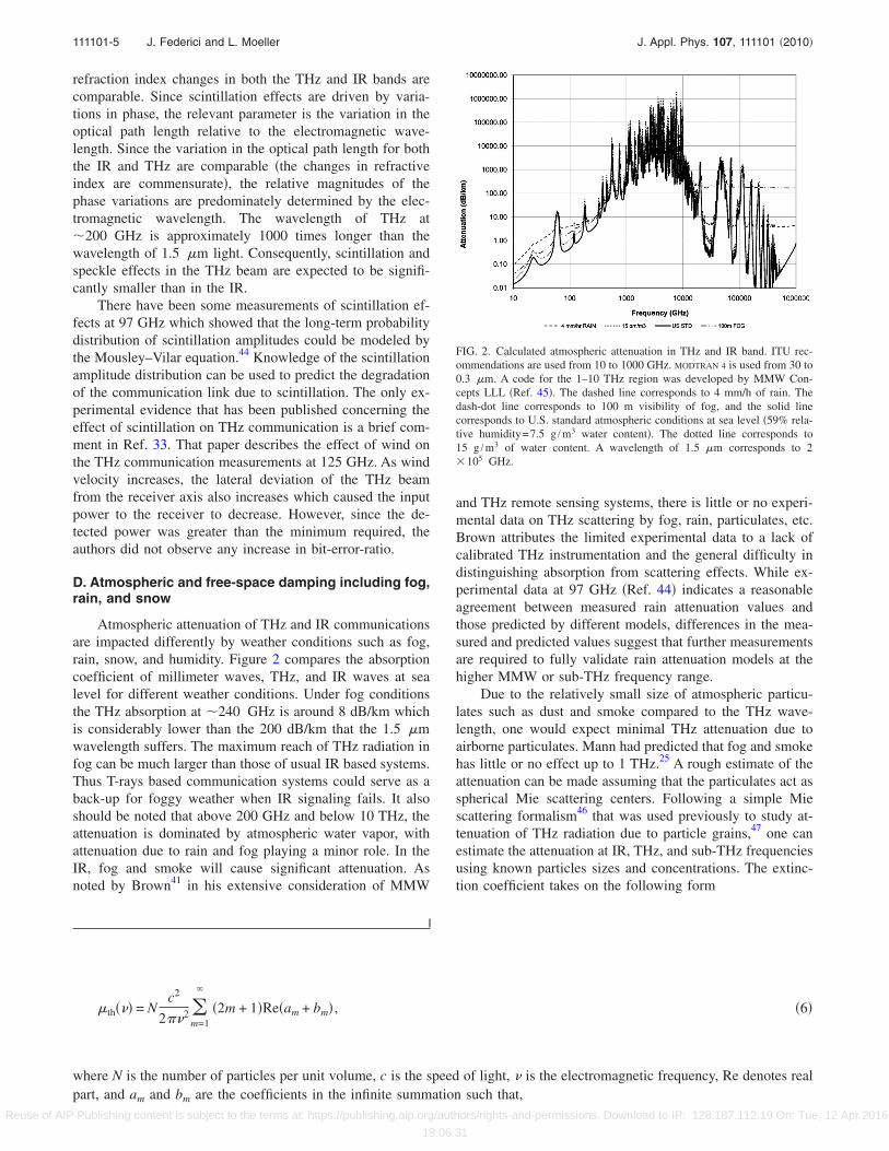
Atmospheric attenuation of THz and IR communicationsare impacted differently by weather conditions such as fog,rain, snow, and humidity. Figure 2 compares the absorptioncoefficient of millimeter waves, THz, and IR waves at sealevel for different weather conditions. Under fog conditionsthe THz absorption at �240 GHz is around 8 dB/km whichis considerably lower than the 200 dB/km that the 1.5 �mwavelength suffers. The maximum reach of THz radiation infog can be much larger than those of usual IR based systems.Thus T-rays based communication systems could serve as aback-up for foggy weather when IR signaling fails. It alsoshould be noted that above 200 GHz and below 10 THz, theattenuation is dominated by atmospheric water vapor, withattenuation due to rain and fog playing a minor role. In theIR, fog and smoke will cause significant attenuation. Asnoted by Brown41 in his extensive consideration of MMW
and THz remote sensing systems, there is little or no experi-mental data on THz scattering by fog, rain, particulates, etc.Brown attributes the limited experimental data to a lack ofcalibrated THz instrumentation and the general difficulty indistinguishing absorption from scattering effects. While ex-perimental data at 97 GHz �Ref. 44� indicates a reasonableagreement between measured rain attenuation values andthose predicted by different models, differences in the mea-sured and predicted values suggest that further measurementsare required to fully validate rain attenuation models at thehigher MMW or sub-THz frequency range.
Due to the relatively small size of atmospheric particu-lates such as dust and smoke compared to the THz wave-length, one would expect minimal THz attenuation due toairborne particulates. Mann had predicted that fog and smokehas little or no effect up to 1 THz.25 A rough estimate of theattenuation can be made assuming that the particulates act asspherical Mie scattering centers. Following a simple Miescattering formalism46 that was used previously to study at-tenuation of THz radiation due to particle grains,47 one canestimate the attenuation at IR, THz, and sub-THz frequenciesusing known particles sizes and concentrations. The extinc-tion coefficient takes on the following form
�th��� = Nc2
2��2 �m=1
�2m + 1�Re�am + bm� , �6�
where N is the number of particles per unit volume, c is the speed of light, � is the electromagnetic frequency, Re denotes realpart, and am and bm are the coefficients in the infinite summation such that,
FIG. 2. Calculated atmospheric attenuation in THz and IR band. ITU rec-ommendations are used from 10 to 1000 GHz. MODTRAN 4 is used from 30 to0.3 �m. A code for the 1–10 THz region was developed by MMW Con-cepts LLL �Ref. 45�. The dashed line corresponds to 4 mm/h of rain. Thedash-dot line corresponds to 100 m visibility of fog, and the solid linecorresponds to U.S. standard atmospheric conditions at sea level �59% rela-tive humidity=7.5 g /m3 water content�. The dotted line corresponds to15 g /m3 of water content. A wavelength of 1.5 �m corresponds to 2�105 GHz.
111101-5 J. Federici and L. Moeller J. Appl. Phys. 107, 111101 �2010�
Reuse of AIP Publishing content is subject to the terms at: https://publishing.aip.org/authors/rights-and-permissions. Download to IP: 128.187.112.19 On: Tue, 12 Apr 2016
19:06:31

am =�m� �y��m�x� − n�m�y��m� �x��m� �y��m�x� − n�m�y��m� �x�
bm =n�m� �y��m�x� − �m�y��m� �x�n�m� �y��m�x� − �m�y��m� �x�
� where � �m�z� = zjm�z��m�z� = zhm
�2��z� � . �7�
Here jm�z� and hm�2��z� are spherical Bessel functions of the
first kind and third kind, respectively. The parameter z can beeither x=2��r /c or y=2��nr /c, where r is the radius of thespherical particle and n is the frequency independent refrac-tive index of the particle.
As an example, we can estimate the attenuation due tobattlefield48 or wildfire particulates and smoke49 using Eqs.�6� and �7�. As shown in Fig. 3, IR wavelengths are stronglyattenuated while THz and sub-THz wavelengths would en-able communications through a much longer link distance.
The attenuation of THz radiation is a function of altitudeand temperature. At higher altitudes, the humidity decreasesleading to a large increase in the maximum distance for THzcommunication. Figure 4 illustrates the predicted channel ca-pacity as a function of frequency for a link from the groundto an unmanned aerial vehicle at 5 km altitude.50 The modelassumes a linear channel which is distorted by white Gauss-ian noise and atmospheric absorption. It calculates the chan-nel capacity based on the Shannon–Hartley theorem and thesystem parameters shown in the legend of Fig. 4. We com-pare three cases such as: �a� the channel bandwidth is fixed at100 MHz �dotted curve� and �b� the channel bandwidthsequals 10% of the carrier frequency �solid curve�. In bothcases we assume signal propagation under vacuum condi-tions �no absorption�. To visualize the atmospheric effects onthe communication link, we assume in case �c� the channelbandwidth to be again 10% of the carrier frequency but alsomoderate rain with 4 mm/h precipitation across the signalpropagation path. Due to strong attenuation at higher THzfrequencies, the effective channel capacity is reduced. Aboveabout 500 GHz the channel capacity drops sharply about fiveorders of magnitude. From this we can conclude that ultra-high capacity channels ��10 Gb /s� with transmission dis-tances of over several kilometers have to operate in the fre-quency range between approximately 100 and 300 GHz.
As an example of how humidity and other weather con-ditions effect THz communication, we theoreticallyconsider51 a communication link operating around 250 GHz
�Fig. 5�. As illustrated in the figure inset, 250 GHz is chosenbecause it is roughly in the middle of the 200–300 GHzatmospheric transmission window. A 100 Gb/s differentialphase-shift keying signal is encoded on the 250 GHz carrieron the transmitter side by means of a Mach–Zehnder modu-lator �MZM�, driving in push-pull operation. The sub-THzsignal propagates through a channel whose water content canbe varied. The inlay in Fig. 5 shows qualitatively the impactof humidity on the transmission band. Clearly, the channelattenuation increases but also the passband is tilted with in-creasing water content. The resulting bandwidth limitationcauses significant distortions which we visualize by simulat-ing the baseband eye diagram of the received signal. Thebaseband signal is generated by down mixing the receivedsignal and launching it through a Mach–Zehnder interferom-eter to convert its phase coding into an amplitude modula-tion. In the first case, we assume standard weather conditionsand plot �Fig. 6� the eye diagram for back-to-back, 1, 2, and3 km transmission distances. To highlight the impairment bychannel bandwidth reduction, we normalize the received sig-nal power �no attenuation by absorption�. After about 3 kmthe eye diagram is completely closed preventing high qualitydata communication. In the second case �Fig. 5� we assumerain at a rate of 4 mm/h across the free space propagationarea. As expected the impairments are even stronger than in
FIG. 3. �Color online� Predicted IR �a�, THz, and sub-THz �b� attenuationdue to spherical airborne particles. For the calculation, parameters compa-rable to battlefield fog oil particles are used: particle density 5�106 /cc,0.2 �m particle radius, and a real index of 1.5.
FIG. 4. �Color online� Channel capacity vs frequency for a link between theground and an airborne vehicle at 5 km altitude. The communications chan-nel follows a line of sight path from the ground to the vehicle at an angle of30° relative to the horizontal. The dotted line corresponds to a fixed band-width of 100 MHz, the solid line corresponds to a 10% bandwidth invacuum, while the dashed line corresponds to 10% bandwidth in rain at arate of 4 mm/h. For this calculation, the transmitter power is assumed to be0.5 W. The diameter of both the transmitter and receiver antennas is 7.5 cm,the noise figure is 8 dB, and the antenna loss is 3 dB.
111101-6 J. Federici and L. Moeller J. Appl. Phys. 107, 111101 �2010�
Reuse of AIP Publishing content is subject to the terms at: https://publishing.aip.org/authors/rights-and-permissions. Download to IP: 128.187.112.19 On: Tue, 12 Apr 2016
19:06:31

the case of standard weather conditions. The eye diagram isalready completely closed after 2 km transmission. Thissimulation shows that weather conditions have to be consid-ered during the system design. To mitigate eye distortions, itcould be better to split the 100 Gb/s data load onto ten chan-nels �each at 10 Gb/s� which are frequency spaced. Otheralternatives could be to apply more bandwidth efficientmodulation formats e.g., quadrature phase-shift keying orsignal equalization on the receiver side.
E. Indoor versus outdoor
In considering the atmospheric attenuation of THzwaves, clearly certain spectral “windows” are available forTHz communication such as the 200–300 GHz window ofFig. 2. Based on the strong atmospheric attenuation, Koch22
concludes that practical THz communication distances arelimited to several tens of meters. Therefore, he predicts thatTHz wireless systems will be limited to medium-link andshort link indoor applications since outdoor scenarios aremuch less likely unless adverse weather conditions are rare.Since both indoor and outdoor THz systems exhibit smallerdiffractive effects at THz frequencies compared to micro-wave frequencies, one would expect that any THz systemwould require line of sight connection between transmitterand receiver. For outdoor systems, this restriction is less of aproblem, for example, if the transmitter and receivers wereplaced on roof-tops of buildings. For indoor systems, onewould have to rely on nonline of sight paths including reflec-tions from walls. Clearly objects or people moving in thebeam path will severely disrupt the communication channel.
Using the Friis equation, a simple estimation for a reli-able indoor THz link suggests that 31 dB gain per antenna isneeded to compensate for free space damping.22 A more de-tailed analysis of the link budget29 estimates that a 10%bandwidth for a 350 GHz THz link would require antennagains of 22 dB, 27 dB, 30 dB, and 33 dB for link distances of1 m, 3 m, 5 m, and 10 m, respectively. The large gain perantenna requires the THz emission to be highly directionaland therefore line of sight detection is required. It is impor-tant to note that this modality of a THz wireless data link isvery different from today’s indoor wireless communicationsystems. Consequently, implementation of an indoor linkTHz communication cannot be just an extension of existingtechnology but must involves the development of new con-cepts and ideas to make it feasible.22
As a further example of the need for new ideas, objectscan block line of sight �people moving around in a room� sothat alternative nonline of sight routes, such as reflectionsfrom walls, are required for a THz communications link.However, since the reflection from typically buildingmaterials52 would introduce additional losses in the links,highly reflecting mirrors are needed. In addition, steerablehigh-gain antennas are required to connect from another pathin case the primary path is blocked.
A key hardware component to implementing indoor THzcommunications is reflective “wall paper” that increases theTHz reflection53 from walls in the event of a nonline of sightpath in a room. The first version of the reflecting paper54
used alternating layers of plastics �real refractive indices 1.7and 1.59�. Stacked alternative layers produced a relativelyhigh reflectivity �76%� at 187 GHz with a �16 GHz band-width. One advantage of these dielectric mirrors is that theyare flexible since they can be fabricated with flexible plastics.However, the maximum reflectivity is limited by the indexdifference between the different layers. An improved versionof the mirrors, described in Ref. 55, consists of alternatingstacks of polypropylene �n=1.53� and high resistivity silicon�n=3.418�. These mirrors, due to the large index differencebetween adjacent layers, have high reflectivity ��95%� forboth s-polarization and p-polarization regardless of incidentangle. The bandwidth of the mirrors is limited to �56 GHzdue to the shifting of the p-polarization reflection band withincident angle. Measurements of the dispersive properties ofthe mirror show that the group delay is on the order of a 5 ps�Ref. 56� with some variation in both the THz frequency�between 0.25 and 0.4 THz� and polarization. Unfortunately,the 63 �m thick crystalline silicon layers are not flexible.However, a flexible high-index dielectric could be fabricatedby mixing high resistivity silicon or TiO2 powder with poly-propylene and coextruded.57 This should improve both thequality and uniformity of a flexible dielectric THz mirror.
In order to characterize the indoor THz communicationchannel, ray tracing, and Monte Carlo simulations wereperformed.22 Ray tracing techniques can be used since theTHz wavelength is small compared to the geometric size oftypical indoor scatterers. Consequently, the THz communica-tion channel can be described using basic parameters such asfree-space attenuation, reflection coefficients from objects inthe room, antenna gains, and the power delay profile. Thepower delay profile refers to the path length difference be-tween the direct line of sight and once or twice reflected THzradiation. Clearly, there will be a time delay in the data at thereceiving antenna depending of which path is taken. If thedata rate were too high, there would be intersymbol interfer-ence �ISI� between data traveling along the multiple paths.
In the simulation environment, models are included forpeople and objects. They are placed randomly in a “cell” orroom and geometrically modeled with planes of appropriatedimensions and THz reflectivity. People are considered to betotally absorbing. Metallic surfaces are considered to reflectTHz radiation perfectly. Reflection of smooth objects aremodeled with Fresnel equations using the known complexindices of refraction and angles of incidence as input data. Insome of the earlier simulations, it was shown that high gain
FIG. 5. �Color online� Simulating distortions to eye diagrams from atmo-spheric attenuation.
111101-7 J. Federici and L. Moeller J. Appl. Phys. 107, 111101 �2010�
Reuse of AIP Publishing content is subject to the terms at: https://publishing.aip.org/authors/rights-and-permissions. Download to IP: 128.187.112.19 On: Tue, 12 Apr 2016
19:06:31

antennas are required for indoor THz communication links.In addition, the placement of people was considered to bestatic. The simulations have been improved26 to consider mo-tion of people including their speed movement, direction ofmotion, and changes in direction of motion. The simulationallows people to be moving in the room for 30 s. The THztransmitter is positioned on the ceiling while the receiver is
located on a desktop in the room. Monte Carlo ray tracingfrom transmitter to receiver establishes THz communicationchannel statistical properties.
The simulation calculates the THz power at the receiverfrom direct line of site paths, once reflected paths, and twicereflected paths. The assumed sensitivity limit for detection is�110 dBm. 30% of all simulated paths are interrupted by
FIG. 6. �Color online� �a� Simulated transmission bands as a function of frequency and link distance for standard weather conditions. Simulated eye diagramsfor transmission distances of �b� 0 km, �c� 1 km, �d� 2 km, and �e� 3 km. Equivalent transmission �f� and eye diagrams for rain at a rate of 4 mm/h at linkdistances of �g� 1 km and �h� 2 km.
111101-8 J. Federici and L. Moeller J. Appl. Phys. 107, 111101 �2010�
Reuse of AIP Publishing content is subject to the terms at: https://publishing.aip.org/authors/rights-and-permissions. Download to IP: 128.187.112.19 On: Tue, 12 Apr 2016
19:06:31

interfering objects. Shadowing effects are observed predomi-nately near static objects such as furniture and walls. Whiledirect line of sight is not feasible due to moving objects,twice reflected power should be avoided: more than �100dBm of power from twice reflected path is available only30% of time. Once reflected paths provide more than �95dBm of the power 65% of the time. Consequently, the indoorlink design should depend on direct line of sight power andonce reflected light.
If the data rate were too high, there would be ISI be-tween the multiple paths. Consequently, the data rate must beslow enough to eliminate ISI. For the simulated channels,90% have a time delay spread of less then 10 ns. From thismaximum time delay, Piesiewicz et al.26 estimate a maxi-mum data rate of 5 Mb/s on a given binary channel. Multiplechannels would be required to achieve gigabit per seconddata rates. Since the THz beams are highly directional,Piesiewicz et al. suggest that “smart” �steerable� antennascould utilize one propagation path at a time and thereforeeliminate ISI. However, such an antenna system still needs tobe developed and evaluated.
In summary, from these simulations it is concluded that�a� alternative routes are needed in which THz reflects off ofwalls to make the system robust against obstacles blocking aprimary line-of-sight path of the THz beam. Only direct lineof sight and once reflected beams should be utilized, �b�dielectric mirrors improve indoor THz communications byincreasing the reflectivity of the walls for nonline of sightlinks, and �c� interference �ISI� among the various beampaths limits the maximum data rate in a single binary chan-nel. Multiple channels are required for gigabit per seconddata rates. �d� Lastly, high gain and smart steerable THzantennas are needed to switch between different link paths tominimize ISI.
III. SECURE WIRELESS THZ COMMUNICATIONS
Many papers in the THz scientific literature—whetherthey discuss THz sources, detectors, components, orcommunication—typically motivate their work by rightfullyclaiming that THz can be used for “secure” communications.Scenarios for secure links might include stealthy short dis-tance communications between vehicles �manned or un-manned� and personnel. Unmanned vehicles may requireshort-distance secure communications links so that they canreceive instructions/transmit data before dispersing to con-duct their remote controlled or autonomous mission. In orderfor the link to be secure, unauthorized personnel should notbe able to identify either the data via eavesdropping on com-munication channels or the presence of a communicationlink.
A major driving force within the United States Depart-ment of Defense �DOD� for secure wireless THz communi-cations may result from plans24 for broadband mobile-on-the-move technologies using both terrestrial and satelliteunits. DOD expects that its requirements beyond 2014 willbe driven by a transition to wideband networks. This shift intechnology mirrors the DOD’s desire to shift from a manualspectrum management plan to an autonomous electromag-
netic spectrum management regime. Beyond 2014, DOD’sspectrum use will be driven by the transition to widebandnetwork waveform wireless networks that contribute toDOD’s network centric warfare model. Through such newtechnology, DOD plans a combat system that can linkground, maritime, aeronautical, and space operations withlayered redundancy, constant connectivity, and situationalawareness. Clearly, for such a system high bandwidth andsecure communications are essential. As part of a completesystem, THz communication links could provide both ofthese essential features.
What are the characteristics of THz communication thatmakes it secure? �a� highly directional beams compared tomicrowave communications, �b� less scattering of radiationcompared to IR wireless, �c� limited propagation distancedue to atmospheric attenuation, �d� encryption of the beam,�e� large channel bandwidth for spread spectrum techniqueswhich enable antijamming and low probability of detectionsystems, and �f� hidden THz signals in the background noise.
Since the frequency of THz radiation is larger than thatof microwaves, beams of THz radiation will diffract less dur-ing free-space propagation. Consequently, as discussed pre-viously, THz communication is typically line-of-sight. Sincethe THz communication beams are highly directional, it ispossible to minimize the area over which THz radiation canbe detected. Microwave wireless communication is less di-rectional; the side-lobes of microwave radiation could bemore easily detected by unauthorized personnel. On the otherextreme of frequency, IR wireless communications are morehighly directional than THz due to the higher carrier fre-quency and smaller potential beam diameter. However, IRradiation is more efficiently scattered by airborne particles.Scattered IR radiation from airborne particles could be de-tected thereby compromising the communication channel.
Intrinsic atmospheric attenuation of THz radiation, whilelimiting the maximum distance for wireless communications,could also be a benefit for secure links. Atmospheric absorp-tion controls signal spreading and limits the detection area.Attenuated wavelengths in IR links �5–7 �m� can be usedfor secure communications.37 For short distances, data trans-mission to the intended target detector can be facilitatedsince the radiation is highly directional. However, the link issecure over longer distances since the radiation is absorbedby the atmosphere. Similarly for THz radiation outside of alimited propagation distance, the THz radiation is highly ab-sorbed by the atmosphere making unwanted detection of datavery difficult. The communication of such systems can belimited by absorption to certain geographic areas thus it willbe much more difficult to detect and intercept the signalsoutside of these areas by eavesdropping even when the sys-tem is running in a broadcasting mode.
In addition to the intrinsic propagation properties thatenable secure THz communication, the technological advan-tage of an ultrawide-bandwidth communication system canreduce an adversary’s chances for successful attacks on aprotected link. For example, the large channel bandwidth ofTHz systems allows for specific protection measures forchannels against various standoff attacks like jamming. An-other advantage of ultrahigh bandwidth THz systems, in ad-
111101-9 J. Federici and L. Moeller J. Appl. Phys. 107, 111101 �2010�
Reuse of AIP Publishing content is subject to the terms at: https://publishing.aip.org/authors/rights-and-permissions. Download to IP: 128.187.112.19 On: Tue, 12 Apr 2016
19:06:31

dition to immunity against standoff jamming attacks, couldbe the ability for completely hiding information exchange.
Communication systems can be roughly subdivided intothree different categories of security. Well-known are meth-ods for encrypting data using codes thus only a receiver withthe right key can decode and read the information. However,this method does not tell the receiver if eavesdropping takesplace along the link. Quantum cryptography establishes dataexchange based on entangled states of particles. Suchschemes indicate to the receiver possible eavesdropping at-tempts. However, eavesdroppers or other unauthorized thirdparties will at least be able to notice that data exchange be-tween sender and receiver is on going. We are suggesting athird and novel kind of secure THz communication: an ultra-wide bandwidth THz channel allows for low probability ofdetection communication such that the communication linkscan be in principle be completely hidden such that a thirdparty would not even notice that signals are exchanged.
The atmospheric THz transmission window with a centerfrequency around 240 GHz offers about 100 GHz of band-width. Spreading the data throughout the 100 GHz band-width makes the system difficult to jam because an adversarywould need to generate high power to overwhelm the THzreceiver. The key to this antijamming technique is to effi-ciently spread the data throughout the available THz band-width using high speed modulators and demodulators. Whileit will take still some time before ultrawide bandwidth modu-lators and demodulators for THz signaling are available,technology for designing multiplexers and demultiplexers toperform logic data processing at 100 Gb/s already exists forultrahigh speed fiber communication at 1.5 �m wave-lengths. We explain the operation principle of the frequencyspreading system by means of Fig. 7. A 1 Mb/s data signal,modulated on the continuous wave �cw� output of a THzsource, is encrypted using a long code sequence at a chip rateof 100 Gb/s. A signal from a jamming attack that does notcarry the correct codeword but possesses the right carrierfrequency and chip rate will get further spectrally broadenedin the decoder by approximately a factor of �2 depending onthe chosen modulation format. Assuming that the transmittersignal is perfectly deconvoluted and has a spectral efficiencyof about 1 bit/s/Hz then narrow bandwidth post filtering atthe decoder output results in a rejection ratio for jammingattacks of about 40 dB, i.e., a potential jammer must possessa technology advantage allowing for building sources that
output several orders of magnitude more power in order toprevent communication. However, it will probably be ex-tremely challenging to modulate 100 Gb/s data signals on acarrier at 240 GHz due to the required unusually highbandwidth-to-carrier-frequency ratios.
As an example, of the frequency spreading, consider abroadcast configuration in which the THz signal is emitted ata power level of �14 dBm �which can be reached, for ex-ample, with an integrated multiplied microwave source�, andintensity-wise evenly radiated across an area of 10 km2 size.A receiver antenna with an effective aperture of 1 m2 wouldcollect about �104 dBm power. This level is sufficient todetect the data at high quality if the decoding can be assumedto be lossless and a 20 dB link margin can account for atmo-spheric propagation losses. A 20 dB power margin to com-pensate for coding and decoding losses can be achieved byincreasing the emitter power to about 4 mW.58 In principlethe receiver noise is limited by the thermal noise of the an-tenna. Thus at room temperature and a signal bandwidth of�Bsig�1 MHz, the antenna noise after narrow bandwidthfiltering accumulates to No=kBT �Bsig=4 fW leading to asignal-to-noise ratio of approximately 10 dB. If a loop finder,used to locate a hidden sender, is steering directly in thedirection of the emitter but does not have the right codesequence to decode the signal then it would measure theemitted signal as a slightly enhanced antenna noise. Morequantitatively, the detected ultrawide bandwidth signalwould appear as an antenna temperature enhancement of�T�−104 dBm / �kB�100 GHz��30 mK.
Although this amount is very small compared to possiblenatural environmental sources, the signal spectrum could inprinciple be completely hidden in the thermal noise by using“channel cooling.” The idea is sketched in Fig. 8. The aper-ture of the THz emitter is surrounded by a mounted cooledplate and radiates into the area where a receiver and a pos-sible loop finder is located. It can be shown that if the loopfinder were far enough away such that its spatial resolution isnot high enough to selectively detect the emitter aperture andthe cooled plate, it would measure only an average antennanoise that could be chosen to be adjusted to the environmentlevel. Hence, the emitter would be in its active frequencyrange spectrally invisible. This example is just intended toillustrate the main idea behind channel cooling for conceal-ing the emitter. The amount of cooling depends on severalsystem parameters like, distance, plate size, received power,apertures of the loop finder and emitter. However, we expectthat under assumption of reasonable system parameters acooling of a few degrees kelvin for a plate with size compa-
FIG. 7. �Color online� Schematic of hidden THz communication link utiliz-ing ultrawide THz bandwidth. The spreading factor is 105 �100 Gb/s:1Mb/s�.
FIG. 8. �Color online� Channel cooling together with spread spectrum tech-niques result in a spectrally invisible emitter.
111101-10 J. Federici and L. Moeller J. Appl. Phys. 107, 111101 �2010�
Reuse of AIP Publishing content is subject to the terms at: https://publishing.aip.org/authors/rights-and-permissions. Download to IP: 128.187.112.19 On: Tue, 12 Apr 2016
19:06:31
rable to the emitter aperture is sufficient to hide the sender.We mention that a more detailed analysis is required to fullydescribe the potential of this method, e.g., the concept worksbest if absorption losses in the atmosphere can be neglected.
IV. THZ HARDWARE FOR WIRELESSCOMMUNICATIONS
In this section, we will review the basic hardware forTHz communications links including methods of THz gen-eration, THz detection, and modulation.
A. Methods of THz generation
1. Optoelectronic
Using optoelectronic generation, one has a variety ofoptions to convert beat frequencies from visible/near IR laserbeams to THz signals including via photodetection �e.g.,unitraveling-carrier photodiode �UTC-PD�, comb frequencygenerators�, cw photomixing, and of course time-domainTHz generation. Since optoelectronic THz sources have beenrecently reviewed,59 we emphasize the highlights that arerelevant for THz communication. In this section, we willfocus on THz generation by ultrafast pulsed lasers, rectifica-tion in fast PDs �e.g., UTC-PD and optical frequency combgenerators�, and cw photomixing.
One of the older methods for the generation and detec-tion of THz radiation utilizes photoconductive antenna�PDA� structures. The PDAs are typically fabricated using afast photoconductive material �for example, low-temperaturegrown GaAs� which acts as a fast switch in a metallic �e.g.,gold� antenna structure. When the unilluminated structure isbiased with a constant voltage, no current flows in the devicesince there are virtually no optical induced charge carriers inthe photoconductive switch. Upon illumination with a shortoptical pulse, for example from a mode-locked Ti:sapphirelaser, the photoconductive switch closes �becomes highlyconductive�, and there is a brief surge of current in the an-tenna structure. By Maxwell’s equations for electromagnet-ics, the time-varying current induces a freely propagatingTHz electromagnetic wave. This structure, which is exten-sively used in THz time-domain spectroscopy �THz-TDS�, iswell-known60 and will not be reviewed here. The pulses,which are generated and received by THz emitter and detec-tor modules, possess a bandwidth of roughly 0.1 to 2.5 THz�wavelength range of 0.12 to 3 mm�. The technology hasbeen sufficiently developed that photoconductive THzsources and detectors, as well as cw photomixers, are com-mercially available from companies such as Physical Do-mains, T-Ray Science, and GigaOptics.
Related to the PDA structure for THz-TDS are cw pho-tomixers for THz radiation.61,62 In the literature, photomixingis sometimes called optical heterodyne conversion in a pho-toconductive switch. However, it should be noted that opti-mizing the photoconductive devices for THz time-domaindoes not necessarily also optimize the devices for cw photo-mixing. In the photomixing process, two colinear optical ornear-IR beams illuminate the photomixing structure. The twobeams are typically narrow optical bandwidth laser sourceswhich are frequency stabilized. For efficient photomixing,
the polarizations, frequencies, and phases of the input opticalbeams must be stable. Similarly �as will be discussed below�a stable pulse repetition rate is important for both THz-TDSand optical frequency comb generation of THz radiation. Thephotomixing process produces a THz beam at the differencefrequency of the two laser beams. The THz frequency isadjusted by tuning the difference frequency of the two IRlaser sources. Whereas the time-domain method produces aTHz pulse that is spectrally broad, the cw mixing methodproduces a narrowband THz signal which is typically limitedby the linewidth of the lasers to roughly 1–2 MHz.
As pointed out by Duffy et al.,61 photomixing is funda-mentally different from second-order ��2� nonlinearitieswhich give rise to difference frequency generation. For the��2� processes, two optical photons produce a single low en-ergy THz photon with low quantum efficiency. Conse-quently, photomixing is more efficient that ��2� differencefrequency generation at low THz frequencies. At higher THzfrequencies, ��2� nonlinearities are more efficient due to para-sitic impedances which limit the THz bandwidth of photo-mixers. Duffy identified several factors which restrict theTHz power of cw photomixers including the lifetime of pho-tocarriers, which limits the high THz frequency response,and thermal dissipation, which caps the optical illuminationpowers and bias voltage levels. For a dual-dipole design, themaximum THz output powers for a single emitter areroughly 3 �W. Arrays of emitters or large gap antennas thatproduce tens of microwatts of THz power are commerciallyavailable.
A recent review of microwave and millimeter wave gen-eration by optical comb techniques can be found in Ref. 63.An optical frequency comb refers to the optical spectrum ofa periodic pulse train. Typically the pulse train is generatedeither by a pulsed mode-locked laser system or by modula-tion of a continuous laser beam. Ideally, the spectrum con-sists of a set of discrete frequencies which are separated infrequency by a stable pulse repetition rate. When the opticalfrequency comb illuminates a high-speed PD detector, theoptical signal is rectified producing an electronic output sig-nal within the electronic bandwidth of the PD detector. Theelectrical output is produced at the frequency interval of thecomb and its harmonics. A key feature of the high-speeddetector is that it must have an electronic bandwidth in thesub-THz to THz range.
Over the past ten years, the UTC-PD has emerged as aviable high-bandwidth device for optical generation ofMMW and sub-THz radiation. UTC-PDs have been devel-oped for both 1.5 �m light using InP/InGaAs �Ref. 64� aswell as 800 nm light using GaAs/AlGaAs.65 The UTC-PD isa heterojunction PD with a p-type absorptive region. Anelectron-hole pair is generated in the absorption layer when aphoton is absorbed. The photogenerated electron movesthrough a nonlight absorbing collection layer and into then-layer at high velocity. Since the hole carrier moves veryslowly in the p-type region due to a diffusion blocking layer,the response of the device—which is in the sub-THzband—is determined by the electron’s velocity. AlternativePD structures, such as the separated-transport recombination
111101-11 J. Federici and L. Moeller J. Appl. Phys. 107, 111101 �2010�
Reuse of AIP Publishing content is subject to the terms at: https://publishing.aip.org/authors/rights-and-permissions. Download to IP: 128.187.112.19 On: Tue, 12 Apr 2016
19:06:31
PD, have been demonstrated as THz emitters as well.66 Arecent review of high-power radiofrequency and THz PDscan be found in Ref. 67.
Variations in the optical frequency comb technique en-able the generation of either multiple sub-THz frequencies orsingle frequencies. For example, a photomixing geometrycan be used. Two single-frequency 1.5 �m lasers beams canbe combined, amplified, and then illuminate the UTC-PD togenerate tunable THz radiation.64,67,68 In another embodi-ment, by splitting the output of an optical comb frequencygenerator, one then can use injection-locked lasers to eachselect out a single optical frequency. By combining and am-plifying the two selected frequencies, and then illuminating aUTC-PD, power is generated at the difference frequency ofthe two visible wavelengths corresponding to an integralmultiple of the combs frequency interval.69 Conceptually, theoptical frequency comb method of THz generation is equiva-lent to all-electronic frequency mixing techniques in whichthe optical frequency comb sources are replace by phase-locked microwave sources which are detuned in frequency tothe THz range.70 The frequency comb is generated by cou-pling the microwave sources to a nonlinear transmission linepulse generator. The generation of THz radiation by opticalfrequency combs from two mode-locked Ti:sapphire lasershas also been demonstrated.71
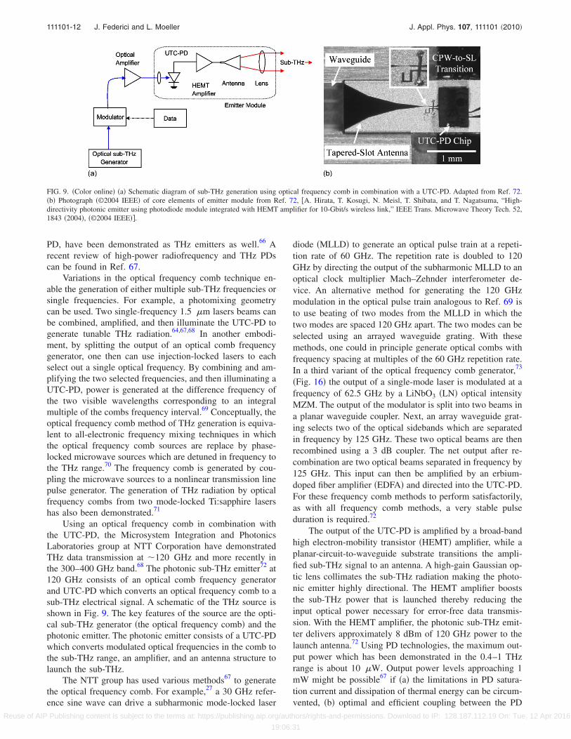
Using an optical frequency comb in combination withthe UTC-PD, the Microsystem Integration and PhotonicsLaboratories group at NTT Corporation have demonstratedTHz data transmission at �120 GHz and more recently inthe 300–400 GHz band.68 The photonic sub-THz emitter72 at120 GHz consists of an optical comb frequency generatorand UTC-PD which converts an optical frequency comb to asub-THz electrical signal. A schematic of the THz source isshown in Fig. 9. The key features of the source are the opti-cal sub-THz generator �the optical frequency comb� and thephotonic emitter. The photonic emitter consists of a UTC-PDwhich converts modulated optical frequencies in the comb tothe sub-THz range, an amplifier, and an antenna structure tolaunch the sub-THz.
The NTT group has used various methods67 to generatethe optical frequency comb. For example,27 a 30 GHz refer-ence sine wave can drive a subharmonic mode-locked laser
diode �MLLD� to generate an optical pulse train at a repeti-tion rate of 60 GHz. The repetition rate is doubled to 120GHz by directing the output of the subharmonic MLLD to anoptical clock multiplier Mach–Zehnder interferometer de-vice. An alternative method for generating the 120 GHzmodulation in the optical pulse train analogous to Ref. 69 isto use beating of two modes from the MLLD in which thetwo modes are spaced 120 GHz apart. The two modes can beselected using an arrayed waveguide grating. With thesemethods, one could in principle generate optical combs withfrequency spacing at multiples of the 60 GHz repetition rate.In a third variant of the optical frequency comb generator,73
�Fig. 16� the output of a single-mode laser is modulated at afrequency of 62.5 GHz by a LiNbO3 �LN� optical intensityMZM. The output of the modulator is split into two beams ina planar waveguide coupler. Next, an array waveguide grat-ing selects two of the optical sidebands which are separatedin frequency by 125 GHz. These two optical beams are thenrecombined using a 3 dB coupler. The net output after re-combination are two optical beams separated in frequency by125 GHz. This input can then be amplified by an erbium-doped fiber amplifier �EDFA� and directed into the UTC-PD.For these frequency comb methods to perform satisfactorily,as with all frequency comb methods, a very stable pulseduration is required.72
The output of the UTC-PD is amplified by a broad-bandhigh electron-mobility transistor �HEMT� amplifier, while aplanar-circuit-to-waveguide substrate transitions the ampli-fied sub-THz signal to an antenna. A high-gain Gaussian op-tic lens collimates the sub-THz radiation making the photo-nic emitter highly directional. The HEMT amplifier booststhe sub-THz power that is launched thereby reducing theinput optical power necessary for error-free data transmis-sion. With the HEMT amplifier, the photonic sub-THz emit-ter delivers approximately 8 dBm of 120 GHz power to thelaunch antenna.72 Using PD technologies, the maximum out-put power which has been demonstrated in the 0.4–1 THzrange is about 10 �W. Output power levels approaching 1mW might be possible67 if �a� the limitations in PD satura-tion current and dissipation of thermal energy can be circum-vented, �b� optimal and efficient coupling between the PD
FIG. 9. �Color online� �a� Schematic diagram of sub-THz generation using optical frequency comb in combination with a UTC-PD. Adapted from Ref. 72.�b� Photograph �©2004 IEEE� of core elements of emitter module from Ref. 72, �A. Hirata, T. Kosugi, N. Meisl, T. Shibata, and T. Nagatsuma, “High-directivity photonic emitter using photodiode module integrated with HEMT amplifier for 10-Gbit/s wireless link,” IEEE Trans. Microwave Theory Tech. 52,1843 �2004�, �©2004 IEEE��.
111101-12 J. Federici and L. Moeller J. Appl. Phys. 107, 111101 �2010�
Reuse of AIP Publishing content is subject to the terms at: https://publishing.aip.org/authors/rights-and-permissions. Download to IP: 128.187.112.19 On: Tue, 12 Apr 2016
19:06:31
and launch antenna can be realized, and �c� arrays of anten-nas can be used to combine the THz power from many PDsinto a more powerful THz source.
2. Microwave frequency multipliers
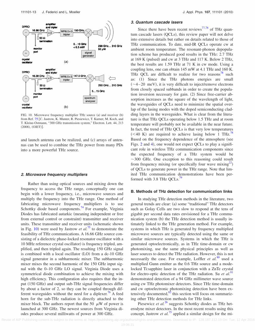
Rather than using optical sources and mixing down thefrequency to access the THz range, conceptually one canbegin with a lower frequency, i.e., microwave sources andmultiply the frequency into the THz range. One method offabricating microwave frequency multipliers is to useSchottky diode based components.74 For example, VirginiaDiodes has fabricated autarkic �meaning independent or freefrom external control or constraint� transmitter and receiverunits. These transmitter and receiver units �schematic shownin Fig. 10� were used by Jastrow et al.75 to demonstrate thefeasibility of THz communications. A 16.66 GHz source con-sisting of a dielectric phase-locked resonator oscillator with a10 MHz reference crystal oscillator� is frequency tripled, am-plified, and then tripled again. The resulting 150 GHz signalis combined with a local oscillator �LO� from a dc-10 GHzsignal generator in a subharmonic mixer. The subharmonicmixer mixes the second harmonic of the 150 GHz input sig-nal with the 0–10 GHz LO signal. Virginia Diode uses asymmetrical diode combination to achieve the mixing withhigh efficiency. This configuration also requires that the in-put �150 GHz� and output sub-THz signal frequencies differby about a factor of 2, so they can be coupled through dif-ferent waveguides without the need for a diplexer.76 A feedhorn for the sub-THz radiation is directly attached to themixer block. The authors report that the 50 �W of power islaunched at 300 GHz. The newest sources from Virginia di-odes produce several milliwatts of power at 300 GHz.
3. Quantum cascade lasers
Since there have been recent reviews77,78 of THz quan-tum cascade lasers �QCLs�, this review paper will not delveinto extensive details but rather on details related to those ofTHz communication. To date, mid-IR QCLs operate cw atambient room temperature. The resonant-phonon depopula-tion scheme has produced good results in the THz: 2.7 THzat 169 K �pulsed� and cw at 3 THz and 117 K. Below 2 THz,the best results are 1.59 THz at 71 K in cw mode. Using acoupling lens, one can obtain 145 mW at 4.1 THz and 160 K.THz QCL are difficult to realize for two reasons78 suchas: �1� Since the THz photons energies are small��4–20 meV�, it is very difficult to inject/remove electronsfrom closely spaced subbands in order to create the popula-tion inversion necessary for gain. �2� Since free-carrier ab-sorption increases as the square of the wavelength of light,the waveguides of QCLs need to minimize the spatial over-lap of the lasing modes with the doped semiconducting clad-ding layers in the waveguides. What is clear from the litera-ture is that THz QCLs operating below 1.5 THz and at roomtemperature will probably not be available in the near future.In fact, the trend of THz QCLs is that very low temperatures��40 K� are required to achieve lasing below 1 THz.78
Based on the frequency dependence of the atmosphere �seeFigs. 2 and 4�, one would not expect QCLs to play a signifi-cant role in wireless THz communication components sincethe expected frequency of a THz system would be�300 GHz. One exception to this reasoning could resultfrom frequency mixing �or specifically four wave mixing22�of QCLs to generate power in the THz range. Note that lim-ited THz communication demonstrations have been per-formed with 3.8 THz QCLs.79
B. Methods of THz detection for communication links
In studying THz detection methods in the literature, twogeneral trends are clear: �a� some “traditional” THz detectorssuch as Golay Cells are two slow to respond at the tens ofgigabit per second data rates envisioned for a THz commu-nication system �b� the THz detection method is usually in-timately linked to the THz generation method. For example,systems in which THz is generated by frequency multipliedmicrowave sources are typically detected using the same orsimilar microwave sources. Systems in which the THz isgenerated optoelectronically, as in THz time-domain or cwphotomixing, use the same physical principles as well aslaser sources to detect the THz radiation. However, this is notnecessarily the case. For example, Loffler et al.80 used amultiplied Gunn emitter as the 0.6 THz source and a mode-locked Ti:sapphire laser in conjunction with a ZnTe crystalfor electro-optic detection of the THz radiation. Su et al.81
demonstrated detection of a 94 GHz millimeter wave sourceusing cw THz photomixer detectors. Since THz time-domainand cw optoelectronic photomixing detection have been ex-tensively documented,82 this section will focus on summariz-ing other THz detection methods for THz links.
Piesewicz et al.26 suggests Schottky diodes as THz het-erodyne mixer detectors. In the most recent results using thisconcept, Jastrow et al.75 applied a similar design for the mi-
FIG. 10. Microwave frequency multiplier THz source �a� and receiver �b�from Ref. 75 �C. Jastrow, K. Munter, R. Piesiewicz, T. Kurner, M. Koch, andT. Kleine-Ostmann, “300 GHz transmission system,” Electron. Lett. 44, 213�2008�, �©IET��.
111101-13 J. Federici and L. Moeller J. Appl. Phys. 107, 111101 �2010�
Reuse of AIP Publishing content is subject to the terms at: https://publishing.aip.org/authors/rights-and-permissions. Download to IP: 128.187.112.19 On: Tue, 12 Apr 2016
19:06:31

crowave multiplier receiver to mix down the incoming THzradiation to a intermediate frequency �IF� of 5 GHz �Fig. 9�.Note that on the receiver side, the fundamental microwaveoscillator is tuned to 16.38 GHz compared to 16.66 GHz onthe transmitter. Consequently, the high frequency signal in-putted to the Schottky diode sub-harmonic receiver mixer is147.5 GHz rather than 150 GHz as in the transmitter. Theintermediate frequency from the sub-harmonic mixer is then2� �150−147.5�=5 GHz. The factor of 2 in the calculationresults from the fact that the second harmonic of the input isused in the mixing process. While the microwave oscillatorsfor both the transmitter and receiver are freely running inde-pendent of each other, their frequencies need to be stabilizedsuch that the IF is fixed.
The experiments by Hirata et al.72 with 120 GHz sub-THz communication systems used a variety of detection sys-tems including Schottky diodes, mixers, and all-electronicInP MMICs.73,33 The MMIC chipset which is used for theall-electronic transmitters and receivers has an on-wafermeasured bit error ratio �BER� of 10−12 at 11 Gb/s. It isinteresting to note that unlike Jastrow et al.’s work in whichthe THz transmitter and receiver operate on the same physi-cal principles �i.e., Schottky devices�, Hirata et al. can usetheir Schottky diode detectors with a variety of THz sourcesincluding optical millimeter wave sources �e.g., optical fre-quency comb/UTC-PD�. Since the THz source and MMICreceivers are independent of each other, the receiver unitmust include a clock recovery circuit.
C. THz antennas
Koch suggests22 that planar antenna structures on dielec-tric lenses and waveguide feed horns are most promising forTHz communications. Planar antenna structures can bereadily integrated with other planar devices whereas wave-guide feed horns have excellent performance and low loss. Inthe case of the UTC-PD THz source, both antenna types areused. Figure 11�a� illustrates a simple THz source comprisedof a planar antenna and silicon lens. �Many standard PDAstructure devices �either time-domain or cw photomixing�have a similar construction�. The THz radiation interactswith the planar antenna as it is radiated into space. The sili-
con lens reduces the divergence of the THz radiation fromthe antenna. An external lens is then used to collimate thelight. Figure 11�b� illustrates the coupling of the UTC-PDoutput first into waveguide structure. The sub-THz signalsfrom the UTC-PD chip are coupled to a tapered slot antennavia a coplanar waveguide. The sub-THz radiation is emittedfrom the antenna into the rectangular wave guide. The wave-guide connects to a feed horn which then couples the radia-tion to free space.72
References 61 and 62 discuss some of the basic scienceand engineering design considerations of planar antennas andcircuitry for cw photomixing antennas. The capacitance ofthe interdigitated electrodes presents a major challenge indesigning high output power antennas. Many of the earlyphotomixers were of the log-spiral type. The advantage ofthe log-spiral is a large THz bandwidth. The disadvantage islow output power at higher THz frequencies. If one is willingto sacrifice THz bandwidth for improved THz power, thendipole and slot antennas are alternatives. Dual dipole de-signs, which have the advantage of efficient designs for high-frequency operation, exhibit more symmetric beam patternsand commensurately higher beam-coupling than single ele-ment designs. Whereas, dual dipole designs work best athigher frequencies, dual-slot antenna designs are bestedsuited for high power output �1 THz since it is more diffi-cult to tune out the capacitance of the interdigitated elec-trodes with the slot design than the dual dipole design. Aspointed out by Duffy et al.,61 log-spirals, single, and dualdipoles and slots have limited optical-power handling capa-bility since the electrode region is limited to a fairly smallarea. The area is limited by �a� partial cancellation of photo-currents due to a phase mismatch across the illuminated ac-tive region and �b� the requirement for a small capacitance ofthe electrode region thereby, enabling inductive tuning.Duffy suggests that a distributed photomixer may improvethe bandwidth and output power of photomixers above 1THz. The company T-Ray Science has introduced arrays ofphotomixers and transmitters that take advantage of the highoptical illumination powers that are available for cw photo-mixing. Using their photomixing antenna arrays, they dem-onstrate 1.2 �W microwatts of THz power for 100 mW of
FIG. 11. �Color online� Left: illustration of a planar antenna, silicon lens, and external lens as a sub-THz source. The planar antenna is fabricated on top ofa thin layer of high speed photoconductive material. Right: schematic of the waveguide-output photodetector module �adapted from Ref. 72�.
111101-14 J. Federici and L. Moeller J. Appl. Phys. 107, 111101 �2010�
Reuse of AIP Publishing content is subject to the terms at: https://publishing.aip.org/authors/rights-and-permissions. Download to IP: 128.187.112.19 On: Tue, 12 Apr 2016
19:06:31
optical input power. Due to the array design, a silicon lens isnot required to collimate the THz beam. Their wide aperture�1 mm� antenna can produce �55 �W of power with 100mW of optical pumping power. In both of their array andwide aperture designs, they do not observe a saturation inTHz power as the optical power is increased.
V. IMPLEMENTATION OF THZ COMMUNICATION
In order to encode a THz carrier with data, clearly somesort of modulation scheme is required. The modulationscheme could either be a direct modulation of a THz source,which is intimately tied to the operational principles of thesource, or an external modulator which in principle could beused on a variety of THz sources. In Secs. V A and V B, webriefly review a variety of modulation methods that are ap-plicable to THz communications. First, we treat modulatorschemes that are specific to a particular method of THz gen-eration. Second, we review modulator methods that are inde-pendent of the particular choice of a THz source. In thisreview, we consider only modulation schemes that can im-press arbitrary data patterns on the THz carrier. In addition towireless communication, data modulation on THz signalscould find application in sensing. When imprinting code se-quences on pulse trains, ranging information from far dis-tance scattering objects can be obtained to define selectivemeasurement intervals. This technique is known fromM-sequence radar where digital beam modulation enhancesthe system’s unambiguous range.83,84
A. THz generator specific modulation schemes
Clearly any modulation methods for THz communica-tion must be capable of encoding THz radiation with randombit patterns in the case of digital data transmission. For bothTHz time-domain systems as well as cw photomixing sys-tems, one of the standard methods for modulating the THzwaveform is a delay line. Most time-domain THz systemsuse slow mechanical scanning delay lines, or mirror shakers�15–300 Hz repetition rate�8 to detect the THz waveform ona point by point basis. Following the example of THz TDS,cw photomixing systems �e.g., two laser sources are typicallymultiplied or mixed in a device such as a PDA structure�typically use a mechanically scanning delay rail85–87 to varythe optical path of the two IR laser beams after the beamshave been combined. The mechanical modulation tech-niques, however, do not easily permit random delays whichwould be required for THz data transmission. Improvementsto the mechanical modulation methods have included piezo-electric delay lines, which can be modulated with arbitraryvoltage waveforms but have limited data rates �kHz�.
1. Optoelectronic systems
One method for directly modulating the THz beam froma photoconductive THz antenna is to directly modulate thebias voltage that is applied to the device.88,89 Since the gen-erated THz is directly proportional to the applied voltageacross the photoconductive gap in these devices, a modula-tion of the applied voltage directly modulates the power ofTHz radiation with a 100% depth of modulation. Modulation
rates of �1 MHz have been demonstrated with thismethod.88 The data rate in these types of modulation experi-ments, however, is limited to the detection bandwidth of thephotoconductive THz detectors to 1MHz.
References 88 and 89 utilize modulation of the THztransmitter bias for time-domain THz communication. Analternative method for modulating cw THz beams, which aregenerated by the optical mixing of two IR beams in a pho-toconductive THz antenna, is to modulate the phase �or am-plitude� of one of the IR beams.90 For this method, the phase�or amplitude� of one of the IR beams is modulated at highspeeds using a Lithium niobate modulator. Moreover, arbi-trary waveforms or bit patterns can be generated by applyingthe appropriate voltage waveform to the Lithium Niobatemodulator. Since the bandwidth of the modulator can be ashigh as the several gigahertz, one can in principle generatevery high bit-rate patterns with this method. The currentlimitation with this method is the bandwidth of the photo-conductive THz receivers.
For cw photomixing, the phase of the THz beam de-pends on the phase difference of the two IR beams whichmix to generate the THz beam. If both beams were phasemodulated in unison, there would be no phase shift imposedon the THz beam. Consequently, for the cw photomixermodulation described in Ref. 90, the phase of only one of theIR beams that generates the THz radiation is modulated. Thedetection of THz by cw photomixers is a phase sensitivemeasurement: the output of the mixer depends on the relativephase between the incoming THz and the two IR beamswhich act as a LO for the mixer. Consequently, the signalfrom the photomixer not only depends on the amplitude ofthe THz signal but also on the phase of the incoming THzsignal which could be altered due to a changing separationbetween the THz transmitter and receiver. If the phase of theTHz beam were unimportant, alternatively one could ampli-tude modulate one or both of the optical beams. This ap-proach of amplitude modulating the optical beams is used todata encode the optical frequency comb/UTC-PD THz gen-erator �described in Sec. IV A 1�. As illustrated in Fig. 16,the optical frequency comb is modulated by data signals viaa Lithium Niobate optical modulator and then amplified by asecond EDFA.91
An alternative method for electronically controlling thephase of a THz beam is through a liquid crystal. While 2�radian phase shifts have been demonstrated, the liquid crystaldevice necessitates low speed switching operation92–94 ren-dering it not useful for the high data rates envisioned for aTHz communication system.
2. Schottky diode mixer systems
Mueller and DeMaria95 proposed a THz modulator basedon a sideband-generator which modulates the phase of theradiation upon reflection from a modulated Schottky diode.Essentially, the device acts as an optical delay line whoseposition can be modulated up to GHz bandwidth. The devicerequires �50–100 mW of input THz power and produces amodulated output of 2–4mW.
Improvements to Schottky mixer technology have en-abled electronic modulation to THz carrier signals. As illus-
111101-15 J. Federici and L. Moeller J. Appl. Phys. 107, 111101 �2010�
Reuse of AIP Publishing content is subject to the terms at: https://publishing.aip.org/authors/rights-and-permissions. Download to IP: 128.187.112.19 On: Tue, 12 Apr 2016
19:06:31

trated in Fig. 10, the modulated data can be introducedthrough the IF port of the mixer �labeled signal generator inthe figure�. The modulator method used by Jastrow et al.75 toboth modulate and detect the frequency multiplied micro-wave sources is based on GaAs Schottky barrier diodes74 asthe nonlinear elements in the THz frequency mixers andmultipliers. Crowe et al. attribute the success of these THzcomponents to three areas of technological innovation:
• The development of advanced fabrication technologiesenabling precise fabrication of terahertz diodes and in-tegrated diode circuits.
• The use of advanced computer aided design tools tosimulate and optimize both the linear and nonlinearportions of the circuit.
• The development of innovative circuit designs. In par-ticular, the inclusion of planar diodes enables the re-moval of the whisker-contact which is by far the mostdifficult and irreproducible part of the componentassembly.
Planar diode chips enables the integration of multiplediodes in the circuit design incorporating more complicatedcircuit designs and higher power throughput. Moreover, theplanar diodes enable the circuits to operate over an entirewaveguide band eliminating the need for mechanical tuningmechanisms.
B. THz generator independent modulation schemes
Several approaches for external THz modulators havebeen discussed96 including ferroelectric materials, liquidcrystals,93,94 and optically or electronically free carriers insemiconductor structures.97,98 Optically or electrically drivenexternal intensity and phase modulators based on activemetamaterials have been demonstrated.99 However, all ofthese methods show limited carrier frequency, modulationbandwidth, or modulation index.
Several THz modulators are based on the free-carrierabsorption of THz radiation by either optically or electricallyinjected free carriers. Encoding of data on the THz beam isachieved by controllably modulating the free-carrier concen-tration in the device. One approach for the direct modulationof THz radiation was demonstrated97 using an optically con-trolled mixed type-I/type-II GaAs/AlAs multiple quantumwell structure. The long photocarrier lifetimes �0.91 ms� inthe structure enables sizeable photoinduced carrier densitiesfor low optical pumping power. When the device is illumi-nated with visible or near IR light, the increase in free-carrierdensity results in free carrier absorption of THz radiationwhich passes through the sample. The device requires low�40 K� temperatures for operation and does not exhibit betterthan a 72% reduction in THz transmission upon illumination.
Another electronic modulator but one that still requiredlow operating temperatures, utilized five identical parabolicquantum wells with equally spaced electron subbands.98 Anapplied electrical field was used to control the electron occu-pation of the quantum wells and thus the THz free-carrierabsorption of the low temperature device. Room temperatureoperation of an electrically driven THz modulator was
achieved by confining a two-dimensional �2D� electron gasat a GaAs/AlGaAs heterointerface.100 Using fabrication tech-nology for producing high electron mobility transistors, theelectron density of the electron gas can be controlled by theapplication of an external gate voltage. Problematically, themaximum depth of modulation for the device was only 3%.The modulation bandwidth was �10 kHz.
A silicon waveguide has also been used as a THz modu-lator. The waveguide is coated with optically transparentfilms enabling illumination of the waveguide and optical in-jection of free carriers in the waveguide to modulate THztransmission. The waveguide modulated required 240 mW ofaverage power at 980 nm to achieve 70% modulation.101
Further improvements to an optically injected free-carrier ab-sorption THz modulator can we achieved by integrating thenonlinear element �e.g., the photodoping region� into a pho-tonic bandgap or metamaterial structure.96 A photonic band-gap or metamaterial structure—for example, fabricated byalternating layers of high and low refractive index—exhibitsspectral bands of high or low photonic transmission. Theintroduction of a nonlinear layer into the otherwise repetitivestructure has two effects such as: �a� introduction of a defectmode by breaking the periodicity of the photonic crystalstructure and �b� potentially strong enhancement of the opti-cal nonlinearity of the defect layer due to high localization ofthe electric field at the defect mode frequency. One structureconstructed from alternating layers of crystalline SiO2 andMgO with a semi-insultating GaAs wafer as a defect layerexhibited a 600 GHz defect band with a FWHM bandwidthof 5–16 GHz. The authors measured the free electron life-time in the GaAs to be 170 ps. Based on this lifetime, theyestimate a maximum switching rate �by optical illumination�to be 5 GHz. They estimate a 50% amplitude modulationcorresponding to a 1015–1016 /cm3 concentration of opticallyinduced carriers in a 1 �m thick photoexcited layer. But noexperimental results verifying these predictions are pre-sented.
Another example of a photonic bandgap/metamaterialstructure for an electronically controllable THz modulator isbased on a 2D slit ring resonator �SRR� structure.102 Themeasured phase and amplitude of a transmitted THz wavethrough the structure is shown in Fig. 12. This single layerstructure exhibits photonic resonances at 0.81 THz from theindividual SRRs and at 1.7 THz from a collective resonanceassociated with the SRR periodicity. The resonators are fab-ricated on a 1 �m thick epitaxial layer of n-doped GaAs.The SRR and GaAs layer form a Schottky diode structure.The application of a voltage to the diode structure modifiesthe free carrier concentration in the depletion zone and con-sequently modifies the tuning of the dielectric properties nearthe optical bandgaps of the SRRs resulting in a voltage con-trolled change in the THz transmission. At zero voltage biasthe photonic bandgap THz transmission resonances are weakbecause the intrinsic free carriers shunt the metamaterial’scapacitive gaps, leading to relatively small THz absorption atresonance. When a reverse bias voltage is applied to thedevice, the depletion region increases in size thereby causingan increase in oscillator strength, and THz absorbance, forboth resonances.
111101-16 J. Federici and L. Moeller J. Appl. Phys. 107, 111101 �2010�
Reuse of AIP Publishing content is subject to the terms at: https://publishing.aip.org/authors/rights-and-permissions. Download to IP: 128.187.112.19 On: Tue, 12 Apr 2016
19:06:31
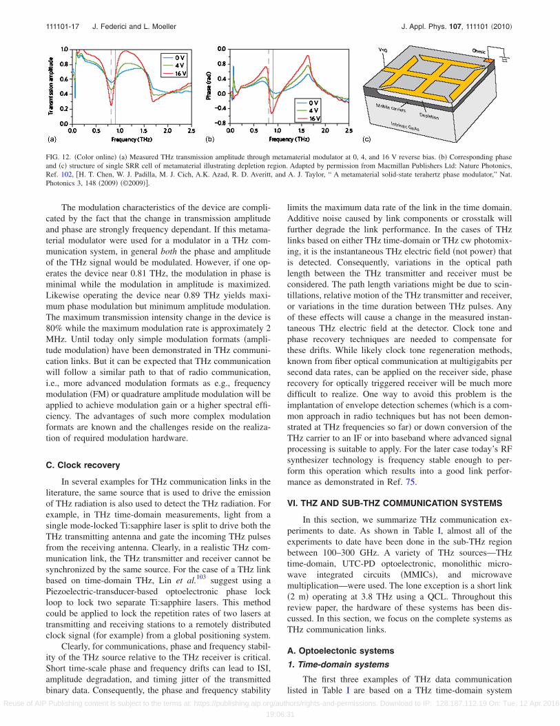
The modulation characteristics of the device are compli-cated by the fact that the change in transmission amplitudeand phase are strongly frequency dependant. If this metama-terial modulator were used for a modulator in a THz com-munication system, in general both the phase and amplitudeof the THz signal would be modulated. However, if one op-erates the device near 0.81 THz, the modulation in phase isminimal while the modulation in amplitude is maximized.Likewise operating the device near 0.89 THz yields maxi-mum phase modulation but minimum amplitude modulation.The maximum transmission intensity change in the device is80% while the maximum modulation rate is approximately 2MHz. Until today only simple modulation formats �ampli-tude modulation� have been demonstrated in THz communi-cation links. But it can be expected that THz communicationwill follow a similar path to that of radio communication,i.e., more advanced modulation formats as e.g., frequencymodulation �FM� or quadrature amplitude modulation will beapplied to achieve modulation gain or a higher spectral effi-ciency. The advantages of such more complex modulationformats are known and the challenges reside on the realiza-tion of required modulation hardware.
C. Clock recovery
In several examples for THz communication links in theliterature, the same source that is used to drive the emissionof THz radiation is also used to detect the THz radiation. Forexample, in THz time-domain measurements, light from asingle mode-locked Ti:sapphire laser is split to drive both theTHz transmitting antenna and gate the incoming THz pulsesfrom the receiving antenna. Clearly, in a realistic THz com-munication link, the THz transmitter and receiver cannot besynchronized by the same source. For the case of a THz linkbased on time-domain THz, Lin et al.103 suggest using aPiezoelectric-transducer-based optoelectronic phase lockloop to lock two separate Ti:sapphire lasers. This methodcould be applied to lock the repetition rates of two lasers attransmitting and receiving stations to a remotely distributedclock signal �for example� from a global positioning system.
Clearly, for communications, phase and frequency stabil-ity of the THz source relative to the THz receiver is critical.Short time-scale phase and frequency drifts can lead to ISI,amplitude degradation, and timing jitter of the transmittedbinary data. Consequently, the phase and frequency stability
limits the maximum data rate of the link in the time domain.Additive noise caused by link components or crosstalk willfurther degrade the link performance. In the cases of THzlinks based on either THz time-domain or THz cw photomix-ing, it is the instantaneous THz electric field �not power� thatis detected. Consequently, variations in the optical pathlength between the THz transmitter and receiver must beconsidered. The path length variations might be due to scin-tillations, relative motion of the THz transmitter and receiver,or variations in the time duration between THz pulses. Anyof these effects will cause a change in the measured instan-taneous THz electric field at the detector. Clock tone andphase recovery techniques are needed to compensate forthese drifts. While likely clock tone regeneration methods,known from fiber optical communication at multigigabits persecond data rates, can be applied on the receiver side, phaserecovery for optically triggered receiver will be much moredifficult to realize. One way to avoid this problem is theimplantation of envelope detection schemes �which is a com-mon approach in radio techniques but has not been demon-strated at THz frequencies so far� or down conversion of theTHz carrier to an IF or into baseband where advanced signalprocessing is suitable to apply. For the later case today’s RFsynthesizer technology is frequency stable enough to per-form this operation which results into a good link perfor-mance as demonstrated in Ref. 75.
VI. THZ AND SUB-THZ COMMUNICATION SYSTEMS
In this section, we summarize THz communication ex-periments to date. As shown in Table I, almost all of theexperiments to date have been done in the sub-THz regionbetween 100–300 GHz. A variety of THz sources—THztime-domain, UTC-PD optoelectronic, monolithic micro-wave integrated circuits �MMICs�, and microwavemultiplication—were used. The lone exception is a short link�2 m� operating at 3.8 THz using a QCL. Throughout thisreview paper, the hardware of these systems has been dis-cussed. In this section, we focus on the complete systems asTHz communication links.
A. Optoelectonic systems
1. Time-domain systems
The first three examples of THz data communicationlisted in Table I are based on a THz time-domain system
FIG. 12. �Color online� �a� Measured THz transmission amplitude through metamaterial modulator at 0, 4, and 16 V reverse bias. �b� Corresponding phaseand �c� structure of single SRR cell of metamaterial illustrating depletion region. Adapted by permission from Macmillan Publishers Ltd: Nature Photonics,Ref. 102, �H. T. Chen, W. J. Padilla, M. J. Cich, A.K. Azad, R. D. Averitt, and A. J. Taylor, “ A metamaterial solid-state terahertz phase modulator,” Nat.Photonics 3, 148 �2009� �©2009��.
111101-17 J. Federici and L. Moeller J. Appl. Phys. 107, 111101 �2010�
Reuse of AIP Publishing content is subject to the terms at: https://publishing.aip.org/authors/rights-and-permissions. Download to IP: 128.187.112.19 On: Tue, 12 Apr 2016
19:06:31
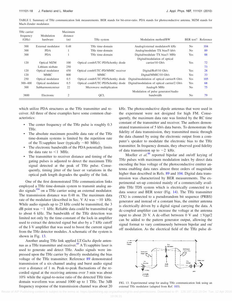
which utilize PDA structures as the THz transmitter and re-ceiver. All three of these examples have some common char-acteristics:
• The center frequency of the THz pulse is roughly 0.3THz.
• The absolute maximum possible data rate of the THztime-domain systems is limited by the repetition rateof the Ti:sapphire laser �typically �80 MHz�.
• The electronic bandwidth of the PDA potentially limitsthe data rate to �1 MHz.
• The transmitter to receiver distance and timing of thegating pulses is adjusted to detect the maximum THzsignal detected at the peak of THz pulse. Conse-quently, timing jitter of the laser or variations in theoptical path length degrades the quality of the link.
One of the first demonstrated THz communication linksemployed a THz time-domain system to transmit analog au-dio signals104 on a THz carrier using an external modulator.The transmission distance was 0.48 m. The maximum datarate of the modulator �described in Sec. V A� was �10 kHz.While audio signals up to 25 kHz could be transmitted, the 3dB point was �1 kHz. Reliable data could be transmitted upto about 6 kHz. The bandwidth of the THz detection waslimited not only by the time-constant of the lock-in amplifierused to extract the detected signal but also by a 7 kHz cutoffof the I-V amplifier that was used to boost the current signalfrom the THz detector modules. A schematic of the system isshown in Fig. 13.
Another analog THz link applied LT:GaAs dipole anten-nas as a THz transmitter and receiver.89 A Ti:sapphire laser isused to generate and detect THz. Audio signals were im-pressed upon the THz carrier by directly modulating the biasvoltage of the THz transmitter. Reference 89 demonstratedtransmission of a six-channel analog and burst audio signalover a distance of 1 m. Peak-to-peak fluctuations of the re-corded signal at the receiving antenna over 3 min was about10% while the signal-to-noise ratio of the detected THz time-domain waveform was around 1000 up to 1 THz. The 3dBfrequency response of the transmission channel was about 20
kHz. The photoconductive dipole antennas that were used inthe experiment were not designed for high FM. Conse-quently, the maximum data rate was limited by the RC timeconstant of the transmitter and receiver. The authors demon-strated transmission of 5 kb/s data bursts. To demonstrate thefidelity of data transmission, they transmitted music throughthe data channel by using the electronic output from a com-puter’s speaker to modulate the electronic bias to the THztransmitter. In frequency domain, they observed good fidelityof data transmission up to �2 kHz.
Moeller et al.88 reported bipolar and on/off keying ofTHz pulses with maximum modulation index by direct dataencoding the bias voltage of the photoconductive emitter an-tenna enabling data rates almost three orders of magnitudehigher than described in Refs. 89 and 104. Digital data trans-mission was characterized by BER measurements. The ex-perimental set-up consisted mainly of a commercially avail-able THz TDS system which is electrically connected to adata source and BER tester �Fig. 14�. The THz transmitter�TX� is connected to a pseudorandom bit sequence �PRBS�generator and instead of a constant bias, the emitter antennais electrically driven by a digital signal carrying the data. Adc-coupled amplifier can increase the voltage at the antennainput to about 20 V. A dc-offset between 0 V and �Vpp/2can be added to the pattern generator output, allowing thesignal format to vary continuously between bipolar and on/off modulation. As the electrical field of the THz pulse di-
TABLE I. Summary of THz communication link measurements. BER stands for bit-error-ratio. PDA stands for photoconductive antenna. MZM stands forMach-Zender modulator.
THz carrierfrequency
�GHz�Modulationhardware
Maximumdistance
�m� THz system Modulation method/BW BER test? Reference
300 External modulator 0.48 THz time-domain Analog/external modulator/6 kHz No 104300 PDA 1 THz time-domain Analog/modulate TX bias/5 kb/s No 89300 PDA 1 THz time-domain Digital/modulate TX bias/1 MHz Yes 88
120 Optical MZM 100 Optical comb/UTC-PD/Schottky diodeDigital/modulation of optical
carrier/10 Gb/s Yes 72
120Lithium niobate
Optical modulator250450 Optical comb/UTC-PD/MMIC receiver Digital/RoF/10 Gb/s Yes
7328
120 MMIC 800 MMIC Digital/MMIC/10 Gb/s Yes 33250 Optical modulator 0.5 Optical comb/UTC-PD/Schottky diode Digital/modulation of optical carrier/8 Gb/s Yes 105
300–400 Optical modulator 0.5 Optical comb/UTC-PD/Schottky diode Digital/modulation of optical carrier/2 Gb/s Yes 68300 Subharmonicmixer 22 Microwave multiplication Analog/6 MHz No 75
3800 Electronic 2 QCLModulation of pulse generator/Audio
bandwidth No 79
FIG. 13. Experimental setup for analog THz communication link using anexternal THz modulator �adapted from Ref. 103�.
111101-18 J. Federici and L. Moeller J. Appl. Phys. 107, 111101 �2010�
Reuse of AIP Publishing content is subject to the terms at: https://publishing.aip.org/authors/rights-and-permissions. Download to IP: 128.187.112.19 On: Tue, 12 Apr 2016
19:06:31

rectly depends on the sign and the amount of the appliedantenna bias, the PRBS data are linearly mapped onto theTHz signal and form its envelope. Sufficient bandwidth ofthe entire electrical path avoids ISI resulting in rectangular-shaped driving data pulses. The output of the detector an-tenna is launched via a high gain transimpedance amplifier��106 V /A� with �580 kHz bandwidth into a preamplifier�PA�. The PA increases the voltage swing to at least 2 Vbefore passing a low pass filter �LP� with 10 MHz 3dB band-width for noise reduction, and finally entering the BERtester’s decision gate. Phase-coupled clock tones synchronizethe pattern generator and BER tester but oscillate asynchro-nously relative to the optical pulse train of the modelockedlaser. The time delay between the optical pulses that activatethe emitter and detector photoconductive switches was ad-justed to maximize the electrical receiver output. Impair-ments due to both electrical ISI �eye closure� and additivenoise were observed. The decision gate’s threshold and sam-pling phase is set for a minimum BER.
At error-free operation �BER�10−8� a high impedancesampling scope recorded 0.5, 1, and 1.5 Mb/s eye diagrams�Figs. 15�b�–15�d�� at the PA output, showing the data-ratedependent ISI caused by limited receiver bandwidth. Eyediagrams of bipolar and on/off modulation with the sametransmitter voltage swing �TVS� look similar. This is ex-pected since the ac-coupled detector blocks offsets and satu-ration effects appear to be small at relevant swing levels. Atlow TVS, receiver noise �Fig. 15�d�� limits the BER=1�10−4 which is manageable using forward error correctingcodes.106 At this BER level we determined the minimal re-quired TVS for different data rates to quantify ISI causedperformance degradations �Fig. 15�e��. A comparison with asecond order LP filter simulations of the receiver shows goodagreement with the measurement. Increasing the TVS widensthe eye which results into a reduced BER. Tests showed thatlong �223−1� and short �27−1� PRBSs yield same BER per-formance.
2. Photonic MMW/UTC-PD optoelectronic systems
The NTT group in Japan has been developing sub-THzcommunication links for the past several years.67 Over that
time they have achieved substantial innovations in hardwarecomponents. Their contributions listed in Table I focus onthree types of systems such as: �a� photonic MMW/UTC-PDsub-THz sources and Schottky diode detectors,72�b� photonicMMW/UTC-PD sub-THz sources and MMIC receivers,73
and �c� an integrated MMIC transmitter and receiver.33 Thefirst two are RoF systems. RoF systems73 refer to modulatingoptical carrier signals at millimeter wave frequencies. Theoptical signals can be routed to a sub-THz transmitter mod-ule using low loss optical fibers. Within the THz transmittermodule, the modulated optical beam is converted to a sub-THz signal using a UTC-PD and then launched into free-space using a feed horn. The details of the hardware arediscussed in Sec. IV A 1. The motivation for the RoF tech-nology as opposed to a conventional millimeter-wave com-munication link are several fold. One drawback of a conven-tional wireless millimeter-wave system is that it requires lineof sight. While a rooftop to rooftop link would be conceptu-ally straight forward, delivering the MMW signal from theinterior of a building, for example, to the roof could be prob-lematic due to attenuating obstacles. Therefore, the availablelocations for setting up wireless equipment are limited. ARoF system could be a very attractive solution to this prob-lem because the millimeter wave signals can be transmitted
FIG. 14. THz communication set-up based on THz TDS system �Ref. 88�.HA high voltage amplifier, PCS photoconductive switch, TA transimpedanceamplifier, PA preamplifier, LP low pass, and Clk clock tone from Ref. 88 �L.Möller, J. Federici, A. Sinyukov, C. Xie, H. C. Lim, and R. C. Giles, “Dataencoding on terahertz signals for communication and sensing,” Opt. Lett.33, 393 �2008� �©2008��.
FIG. 15. �Color online� Eye diagrams at different date rates and error-freeoperation ��a�–�c�� and�d� at 1.5 Mb/s with BER=10−4; measured and simu-lated required TVS at different data rates �e�. Simulated eye diagrams showgood agreement with Figs. 15�a�–15�c� from Ref. 88 �L. Möller, J. Federici,A. Sinyukov, C. Xie, H. C. Lim, and R. C. Giles, “Data encoding on tera-hertz signals for communication and sensing,” Opt. Lett. 33, 393 �2008��©2008��.
111101-19 J. Federici and L. Moeller J. Appl. Phys. 107, 111101 �2010�
Reuse of AIP Publishing content is subject to the terms at: https://publishing.aip.org/authors/rights-and-permissions. Download to IP: 128.187.112.19 On: Tue, 12 Apr 2016
19:06:31

over long distances by using optical fibers with an opticalfrequency comb as discussed in Sec. IV A 1. Conceptually,one can generated the optical frequency comb, encode thedata on the optical carrier using an optical modulator, andthen route the optical signals through a building to a sub-THz transmitter located on a rooftop. Since a high-gain sub-THz antenna requires highly precise alignment, scintillationeffects due to wind or even the motion of buildings willcause variations in the received power. Figure 16 shows apossible configuration for a RoF system which would firsttransmit optical carriers through a building via fibers, convertthe optical comb to wireless sub-THz radiation, and thentransform received wireless sub-THz radiation back into in-frared light which is then launched back to optical fibers.
Another motivation and advantage of the RoF system isthat it can easily be integrated into a high-speed optical fibercommunication link as part of a first mile and last milesolution.27 Conceptually, optical communication systems canprovide high-speed �40 Gb/s�, long distance point-to-pointcommunication via optical fibers. However, in order to dis-tribute data from a node to the end users, one needs to main-tain the high data rate as the data is split among multiplemobile users.
Figure 16 shows a schematic of a RoF wireless link sys-tem. The transmitter is composed of a low-phase-noise pho-tonic millimeter-wave generator �described in Sec. IV A 1�which outputs an optical frequency comb: an optical carrierupon which a sub-THz signal is impressed. The output of thephotonic millimeter-wave generator passes through the datamodulator �described in Sec. V A�. At this point, the digitaldata �which is generated by a bit-error-rate tester� is encodedonto the optical/sub-THz carrier. When the data modulatedoptical frequency comb illuminates the UTC-PD module, theoptical frequency comb is electro-optically converted andamplified by the UTC-PD module to a sub-THz signal. Thegenerated sub-THz signal �with data� is then transmittedfrom a high-gain antenna. In Hirata’s earlier work �see, forexample, Ref. 72�, the received sub-THz signal can be de-tected by either a Schottky diode detector or mixer. TheSchottky diode detection system exhibited a 10−10 BER witha projected maximum distance of 100 m. For the RoF systemdescribed in Ref. 73, the received sub-THz signal is detected,amplified, and demodulated by a receiver module using areceiver MMIC chip.107 The demodulated data signals are
then converted to an optical signal by an electro-optic con-verter and launched into a fiber-optic cable. Finally the opti-cal signal is converted into an electronic signal and launchedto a BER tester. A BER below 10−12 at 10 Gb/s is reportedfor a wireless link distance of 250 m. The estimated maxi-mum transmission distance is about 2 km.28
B. Integrated circuit systems
While the 1.5 �m fiber-optical components of the RoFsystems enable easy integration with high-speed optical com-munications systems, there is a drawback of the photonicapproach in terms of additional optical components, systemsize, total cost, and added power consumption. Clearly, re-placing the optoelectronic THz source with an integratedelectronic device—which would work in concert with theMMIC receiver chip—could eliminate many of these issues.Yamaguchi et al.33 implemented a flexible coplanar wave-guide MMIC chipset,108 which included amplifiers, modula-tors, and demodulators, as the sub-THz transmitter and re-ceiver in a 10 Gb/s wireless link. The link exhibited a 10−12
BER over 800 m distance. The authors estimate a maximumtransmission distance of 2 km. An interesting note in theirpaper is that scintillation effects due to the effect of wind onthe propagating sub-THz radiation were measurable. Aswind velocity increased, the receiver axis deviation also in-creased which caused the input power to decrease. However,since the input power even in the presence of the wind wasgreater than the minimum required, the authors did not ob-serve any increase in BER due to the wind.
C. Microwave multiplier systems
Analog video signal transmission has been demonstratedat 300 GHz using a microwave multiplier system.75 The sys-tem, described in Sec. IV A 2�, consists of a frequency mul-tiplied �6�� 16.66 GHz LO. The resulting 150 GHz signal isconverted to a 290–310 GHz signal using a subharmonicmixer and a dc-10 GHz signal generator. The receiver LO is16.38 GHz so that the IF of the receiver �5 GHz� is detectedusing heterodyne methods. To demonstrate data transmis-sion, a color video baseband signal with 6 MHz bandwidth ismodulated on a UHF carrier �855.25 MHz� which then actsas the “signal generator” to be transmitted over a THz link.At the receiver, the 5 GHz IF is mixed down to baseband andfeed to a standard TV card. The TV card input requires aminimum signal to noise ratio of 40 dB. The image quality isviewed on computer screen. Using just the THz feed horns,excellent picture quality is reported upto 0.5 m with signifi-cant degradation observable at transmission distances of 0.8m. When lenses collimate the THz radiation, a maximumlink distance of 22 m is achieved.
VII. SUMMARY AND CONCLUSIONS
THz communication links potentially offer several ad-vantages compared to microwave and IR wireless links in-cluding inherently higher bandwidth compared to microwavelinks and less attenuation under foggy weather or smoke con-ditions compared to IR links. Moreover, by taking advantageof the wide bandwidth available in the THz range, one can
FIG. 16. �a� Schematic of experimental setup for outdoor data communica-tion �adapted from Ref. 73�. �b� Details of the various subsystems �adaptedfrom Ref. 73�.
111101-20 J. Federici and L. Moeller J. Appl. Phys. 107, 111101 �2010�
Reuse of AIP Publishing content is subject to the terms at: https://publishing.aip.org/authors/rights-and-permissions. Download to IP: 128.187.112.19 On: Tue, 12 Apr 2016
19:06:31

implement secure communications links in the THz range.While future THz communications links will probably utilizeTHzIC/MMIC due to their inherently lower-cost comparedto optoelectronic systems, near-term systems utilizing fre-quency multipliers can provide milliwatts of THz power andseveral gigahertz of bandwidth which should be suitable forreasonable �several hundreds of meters� link distances. Op-toelectronic based systems, such as RoF systems, may findniche applications in which direct coupling of wireless THzlinks to high-speed fiber-optical systems is the major consid-eration. Several key challenges remain. First and for most isthe development of high power THz sources within the THzatmospheric transmission windows, as well as compatiblehigh sensitivity detectors, and modulation hardware. Sinceone of the potentially major benefits of THz communicationsis the wide bandwidth, hardware systems that take advantageof the 100 GHz of available bandwidth should be developedover the next several years. Aside from hardware issues, theattenuation and scintillation properties of the atmosphere, in-cluding the effect of fog, rain, and smoke, need to be experi-mentally quantified as THz systems are developed. Lastly,analogous to the development of radio communication, ad-vanced modulation formats need to be applied to the THzlinks to achieve modulation gain or a higher spectral effi-ciency.
ACKNOWLEDGMENTS
The authors would like to thank all of our colleagueswhose work contributed to this review paper. Technical dis-cussions with S. Personick and C. Xie are gratefully ac-knowledged.
1A. Redo-Sanchez and X.-C. Zhang, IEEE J. Sel. Top. Quantum Electron.14, 260 �2008�.
2M. Tonouchi, Nat. Photonics 1, 97 �2007�.3P. H. Siegel, IEEE Trans. Microwave Theory Tech. 50, 910 �2002�.4P. Mukherjee and B. Gupta, Int. J. Infrared Millim. Waves 29, 1091�2008�.
5G. K. Kitaeva, Laser Phys. Lett. 5, 559 �2008�.6K. L. Vodopyanov, Laser Phys. 19, 305 �2009�.7V. Bratman, M. Glyavin, T. Idehara, Y. Kalynov, A. Luchinin, V.Manuilov, S. Mitsudo, I. Ogawa, T. Saito, Y. Tatematsu, and V. Zapevalov,IEEE Trans. Plasma Sci. 37, 36 �2009�.
8W. L. Chan, J. Deibel, and D. M. Mittleman, Rep. Prog. Phys. 70, 1325�2007�.
9R. Appleby and H. B. Wallace, IEEE Trans. Antennas Propag. 55, 2944�2007�.
10M. C. Kemp, 33rd International Conference on Infrared and MillimeterWaves and the 16th International Conference on Terahertz Electronics,IRMMW-THz 2008 �IEEE, New Jersey, 2008�.
11J. F. Federici, B. Schulkin, F. Huang, D. Gary, R. Barat, F. Oliveira, and D.Zimdars, Semicond. Sci. Technol. 20, S266 �2005�.
12J. F. Federici, D. Gary, R. Barat, and Z.-H. Michalopoulou, in Counter-Terrorism Detection Techniques of Explosives, edited by J. Yinon�Elsevier, Boston, 2007�.
13J. A. Zeitler and L. F. Gladden, Eur. J. Pharm. Biopharm. 71, 2 �2009�.14P. H. Siegel, IEEE Trans. Microwave Theory Tech. 52, 2438 �2004�.15Y. L. Hor, J. F. Federici, and R. L. Wample, Appl. Opt. 47, 72 �2008�.16J. F. Federici, R. L. Wample, D. Rodriguez, and S. Mukherjee, Appl. Opt.
48, 1382 �2009�.17D. Zimdars, J. S. White, G. Fichter, G. Sucha, and S. Williamson, in
Ultrasonic and Advanced Methods or Non Destructive Testing and Mate-rials Characterization, edited by C. H. Chen �World Scientific, Singapore,2007�, Chap. 13, pp. 303–323.
18S. K. Reynolds, B. A. Floyd, U. R. Pfeiffer, T. Beukema, J. Grzyb, C.
Haymes, B. Gaucher, and M. Soyuer, IEEE J. Solid-State Circuits 41,2820 �2006�.
19R. Heidemann, R. Hofstetter, and H. Schmuck, IEEE MTT-S Int. Micro-wave Symp. Dig. 1, 483 �1994�.
20http://www.fcc.gov/oet/spectrum/.21S. Cherry, IEEE Spectrum 41, 50 �2004�.22M. Koch, Terahertz Frequency Detection and Identification of Materials
and Objects, Nato Science for Peace and Security Series—B: Physics andBiophysics, edited by R. E. Miles, X. C. Zhang, H. Eisele, and A. Krotkus�Springer Science and Business Media, Dordrecht, Netherlands, 2007�, pp.325–338.
23S. Roy, J. Foerster, V. Srinivasa Somayazulu, and D. Leeper, Proc. IEEE92, 295 �2004�.
24Spectrum Management for the 21st Century The President’s SpectrumPolicy Initiative, Federal Strategic Spectrum Plan, March 2008. http://www.ntia.doc.gov/reports/2008/FederalStrategicSpectrumPlan2008.pdf.
25C. M. Mann, “Towards Terahertz Communications Systems,” TerahertzSources and Systems, edited by R. Miles et al. �Kluwer Academic, Neth-erlands, 2001�, pp. 261–267.
26R. Piesiewicz, J. Jemai, M. Koch, and T. Kürner, Proc. SPIE 5727, 166�2005�.
27A. Hirata, M. Harada, and T. Nagatsuma, J. Lightwave Technol. 21, 2145�2003�.
28A. Hirata, T. Nagatsuma, T. Kosugi, H. Takahashi, R. Yamaguchi, N.Shimizu, N. Kukutsu, K. Murata, Y. Kado, H. Ikegawa, H. Nishikawa, andT. Nakayama, Proc. SPIE 6772, 67720B �2007�.
29R. Piesiewicz, T. Kleine-Ostmann, N. Krumbholz, D. Mittleman, M.Koch, J. Schoebel, and T. Kurner, IEEE Antennas Propag. Mag. 49, 24�2007�.
30H.-H. Chen, CDMA Technologies �Wiley, New York, 2007�, Chaps. 2.6.5–2.6.7.
31T. Nagatsuma, Talk PL-4 Conference Digest of the 2006 Joint 31st Inter-national Conference on IR and MMW, Sept. 18–22, 2006 Shanghai,�China� �IEEE, New Jersey�.
32http://www.ntia.doc.gov/osmhome/allochrt.pdf.33R. Yamaguchi, A. Hirata, T. Kosugi, H. Takahashi, N. Kukutsu, T. Na-
gasuma, Y. Kado, H. Ikegawa, H. Nishikawa, and T. Nakayama, RWS2008, Jan. 22–24, 2008 Orlando, FL �IEEE, New Jersey� p. 695.
34V. Jungnickel, T. Haustein, A. Forck, and C. Von Helmolt, Electron. Lett.37, 314 �2001�.
35K.-D. Langer and J. Grubor, Proceedings of 2007 9th International Con-ference on Transparent Optical Networks, ICTON, July 1–5, 2007 Rome,�IEEE, New Jersey�, Vol. 3, pp. 146–151.
36N. Cvijetic, D. Qian, and T. Wang, Optical Fiber Conference, 2008 Feb.24–28, 2008 San Diego �OSA, Washington, DC�.
37D. Kedar and S. Arnon, IEEE Commun. Mag. 42, S2 �2004�.38K. Wang and D. M. Mittleman, Nature �London� 432, 376 �2004�.39B. Bowden, J. A. Harrington, and O. Mitrofanov, J. Appl. Phys. 104,
093110 �2008�.40J.-K. Lu, C.-P. Yu, H.-C. Chang, H.-W. Chen, and Y.-T. Li, Appl. Phys.
Lett. 92, 064105 �2008�.41E. R. Brown, in Terahertz Sensing Technology, edited by D. L. Woolard,
W. R. Loerop, and M. S. Shur �World Scientific, Singapore, 2003�, Vol. 2;Intern. J. High Speed Electron. Systems 13, 995 �2003�.
42R. L. Freeman, Radio System Design for Telecommunications, 2nd ed.�Wiley, New York, 1997�, p. 7.
43L. C. Andrews and R. L. Phillips, Laser Beam Propagation Through Ran-dom Media �SPIE, Bellingham, WA, 1998�.
44S. A. Khan, A. N. Tawfik, C. J. Gibbins, and B. C. Gremont, IEEE Trans.Antennas Propag. 51, 3109 �2003�.
45The original calculation was published in M. J. Rosker and H. B. Wallace,“Imaging through the atmosphere at terahertz frequencies”, 2007 IEEEMTT-S International Microwave Symposium Digest, art. no. 4263933, pp.773–776. Fig. 2 is based on an improved calculation from MMW con-cepts. www.mmwconcepts.com.
46C. F. Bohren and D. R. Huffman, Absorption and Scattering of Light bySmall Particles �Wiley, New York, 1983�.
47A. Bandyopadhyay, A. Sengupta, R. B. Barat, D. E. Gary, J. F. Federici,M. Chen, and D. B. Tanner, Int. J. Infrared Millim. Waves 28, 969 �2007�.
48B. Wu, B. Marchant, and M. Kavehrad, Military Communications Confer-ence, MILCOM 2007, Oct. 29–31, 2007 Orlando, FL �IEEE, New Jersey�,pp. 1–6.
49Y. M. Noh, D. Muller, D. H. Shin, H. Lee, J. S. Jung, K. H. Lee, M. Cribb,Z. Li, and Y. J. Kim, Atmos. Environ. 43, 879 �2009�.
111101-21 J. Federici and L. Moeller J. Appl. Phys. 107, 111101 �2010�
Reuse of AIP Publishing content is subject to the terms at: https://publishing.aip.org/authors/rights-and-permissions. Download to IP: 128.187.112.19 On: Tue, 12 Apr 2016
19:06:31

50H. B. Wallace, �private communication�. www.mmwconcepts.com.51H. B. Wallace and C. Xie, �private communication�. www.mmwcon-
cepts.com.52R. Piesiewicz, T. Kleine-Ostmann, N. Krumbholz, D. Mittleman, M.
Koch, and T. Kürner, Electron. Lett. 41, 1002 �2005�.53S. Wietzke, C. Jansen, and M. Koch, Kunststoffe International 99, 37
�2009�.54D. Turchinovich, A. Kammoun, P. Knobloch, T. Dobbertin, and M. Koch,
Appl. Phys. A: Mater. Sci. Process. 74, 291 �2002�.55N. Krumbholz, K. Gerlach, F. Rutz, M. Koch, R. Piesiewicz, T. Kürner,
and D. Mittleman, Appl. Phys. Lett. 88, 202905 �2006�.56I. A. Ibraheem, N. Krumbholz, D. Mittleman, and M. Koch, IEEE Microw.
Wirel. Compon. Lett. 18, 67 �2008�.57S. Wietzke, C. Jansen, F. Rutz, D. M. Mittleman, and M. Koch, Polym.
Test. 26, 614 �2007�.58The company Virginia Diodes �VDI� offers a 300 GHz source based on
frequency multiplier chain technology with 30 mW output power.59D. Saeedkia and S. Safavi-Naeini, J. Lightwave Technol. 26, 2409 �2008�.60See, for example, D. Mittleman, in Sensing with Terahertz Radiation, ed-
ited by D. Mittleman �Springer, New York, 2003�.61S. M. Duffy, S. Verghese, and K. A. McIntosh, in Sensing with Terahertz
Radiation, edited by D. Mittleman �Springer, New York, 2003�.62E. R. Brown, in Terahertz Sensing Technology, Electronic Devices and
Advanced Systems Technology, edited by D. L. Woolard, W. R. Loerop,and M. S. Shur �World Scientific, New Jersey, 2003�, Vol. 1.
63See collection of papers in T. E. Darcie, A. Stohr, and P. K. L. Yu, J.Lightwave Technol. 26, 2336 �2008�.
64H. Ito, Y. Hirota, A. Hirata, T. Nagatsuma, and T. Ishibashi, Electron. Lett.37, 1225 �2001�.
65Y.-T. Li, J. W. Shi, C. Y. Huang, N.-W. Chen, S.-H. Chen, J.-I. Chyi, andC.-L. Pan, IEEE Photon. Technol. Lett. 20, 1342 �2008�.
66Y. T. Li, J.-W. Shi, C. Y. Huang, N. W. Chen, S.-H. Chen, J. I. Chyi, Y. C.Wang, C.-S. Yang, and C. L. Pan, IEEE J. Quantum Electron. 46, 19�2010�.
67T. Nagatsuma, H. Ito, and T. Ishibashi, Laser Photonics Rev. 3, 123�2009�.
68T. Nagatsuma, H.-J. Song, Y. Fujimoto, K. Miyake, A. Hirata, K. Ajito, A.Wakatsuki, T. Furuta, N. Kukutsu, and Y. Kado, MWP09—2009 Interna-tional Topical Meeting on Microwave Photonics, 2009 Oct. 14–26, 2008Valencia, Spain �IEEE, New Jersey�.
69S. Fukushima, C. F. C. Silva, Y. Muramoto, and A. J. Seeds, J. LightwaveTechnol. 21, 3043 �2003�.
70D. W. Van der Weide, J. Murakowski, and F. Keilmann, IEEE Trans.Microwave Theory Tech. 48, 740 �2000�.
71T. Yasui, Y. Kabetani, E. Saneyoshi, S. Yokoyama, and T. Araki, Appl.Phys. Lett. 88, 241104 �2006�.
72A. Hirata, T. Kosugi, N. Meisl, T. Shibata, and T. Nagatsuma, IEEE Trans.Microwave Theory Tech. 52, 1843 �2004�.
73A. Hirata, H. Takahashi, R. Tamaguchi, T. Kosugi, K. Murata, T. Nagat-suma, N. Kukutsu, and Y. Kado, J. Lightwave Technol. 26, 2338 �2008�.
74T. W. Crowe, D. W. Porterfield, J. L. Hesler, and W. L. Bishop, Joint 31stInternational Conference on Infrared Millimeter Waves and 14th Interna-tional Conference on Terahertz electronics, September 2006 �IEEE, NewJersey, 2006�.
75C. Jastrow, K. Munter, R. Piesiewicz, T. Kurner, M. Koch, and T. Kleine-Ostmann, Electron. Lett. 44, 213 �2008�.
76Tom Crowe, Virginia Diodes �private communication�.77S. Kumar and A. W. M. Lee, IEEE J. Sel. Top. Quantum Electron. 14, 333
�2008�.78B. S. Williams, Nat. Photonics 1, 517 �2007�.79P. D. Grant, S. R. Laframboise, R. Dudek, M. Grat, A. Bezinger, and H. C.
Liu, Electron. Lett. 45, 952 �2009�.80T. Loeffler, T. May, C. A. Weg, A. Alcin, B. Hils, and H. G. Roskos, Appl.
Phys. Lett. 90, 091111 �2007�.81K. Su, Z. Liu, R. Barat, D. Gary, Z.-H. Michalopoulou, and J. F. Federici,
Appl. Opt. 49, E13 �2010�.82Sensing with Terahertz Radiation D. Mittleman �Springer, New York,
2003�.83J. Sachs, P. Peyerl, and M. Rossberg, IEEE Proc. IMTC/99, Venice, Italy,
May 24–26, 1999 �IEEE, New Jersey� Vol. 3, pp. 1390–1395.84D. J. Daniels, “Ground Penetrating Radar,” 2nd ed. �IEE, London, 2004�,
Chap. 6.6.2.85A. Nahata, J. T. Yardley, and T. F. Heinz, Appl. Phys. Lett. 75, 2524
�1999�.86K. J. Siebert, H. Quast, R. Leonhardt, T. Loffler, M. Thomson, T. Bauer,
H. G. Roskos, and S. Czasch, Appl. Phys. Lett. 80, 3003 �2002�.87N. Karpowicz, H. Zhong, J. Xu, K.-I. Lin, J.-S. Hwang, and X.-C. Zhang,
Semicond. Sci. Technol. 20, S293 �2005�.88L. Möller, J. Federici, A. Sinyukov, C. Xie, H. C. Lim, and R. C. Giles,
Opt. Lett. 33, 393 �2008�.89T.-A. Liu, G.-R. Lin, Y.-C. Chang, and C.-L. Pan, Opt. Express 13, 10416
�2005�.90A. M. Sinyukov, Z. Liu, Y. L. Hor, K. Su, R. B. Barat, D. E. Gary, Z.-H.
Michalopoulou, I. Zorych, J. F. Federici, and D. Zimdars, Opt. Lett. 33,1593 �2008�.
91A. Hirata, T. Kosugi, H. Takahashi, R. Yamaguchi, F. Nakajima, T. Furuta,H. Ito, H. Sugahara, Y. Sato, and T. Nagatsuma, IEEE Trans. MicrowaveTheory Tech. 54, 1937 �2006�.
92H.-Y. Wu, C.-F. Hsieh, T.-T. Tang, R.-P. Pan, and C.-L. Pan, IEEE Photon.Technol. Lett. 18, 1488 �2006�.
93Z. Ghattan, T. Hasek, R. Wilk, M. Shahabadi, and M. Koch, Opt. Com-mun. 281, 4623 �2008�.
94R. Wilk, N. Vieweg, A. Kopschinski, and M. Koch, Opt. Express 17, 7377�2009�.
95E. R. Mueller and A. J. DeMaria, Proc. SPIE 5727, 151 �2005�.96P. Kužel and F. Kadlec, C. R. Phys. 9, 197 �2008�.97I. H. Libon, S. Baumgartner, M. Hempel, N. E. Hecker, J. Feldmann, M.
Koch, and P. Dawson, Appl. Phys. Lett. 76, 2821 �2000�.98R. Kersting, G. Strasser, and K. Unterrainer, Electron. Lett. 36, 1156
�2000�.99H.-T. Chen, W. J. Padilla, J. O. Zide, A. C. Gossard, A. J. Taylor, and R.
D. Averitt, Nature �London� 444, 597 �2006�.100T. Kleine-Ostmann, P. Dawson, K. Pierz, G. Hein, and M. Koch, Appl.
Phys. Lett. 84, 3555 �2004�.101D. G. Cooke and P. U. Jepsen, Opt. Express 16, 15123 �2008�.102H.-T. Chen, W. J. Padilla, M. J. Cich, A. K. Azad, R. D. Averitt, and A.
J. Taylor, Nat. Photonics 3, 148 �2009�.103G. R. Lin, Y. C. Chang, T. A. Liu, and C. L. Pan, Appl. Opt. 42, 2843
�2003�.104T. Kleine-Ostmann, K. Pierz, G. Hein, P. Dawson, and M. Koch, Elec-
tron. Lett. 40, 124 �2004�.105H. J. Song, K. Ajito, A. Hirata, A. Wakatsuki, T. Furuta, N. Kukutsu, and
T. Nagatsuma, 34th International Conference on Infrared, Millimeter, andTerahertz Waves, IRMMW-THz 2009, Sept. 21–25, 2009 Busan �Korea��IEEE, New Jersey�.
106See e.g. International Telecommunications Union standard ITU-TG.975.1 at http://www.itu.int.
107T. Kosugi, T. Shibata, T. Enoki, M. Muraguchi, A. Hirata, T. Nagatsuma,and H. Kyuragi, IEEE Int. Microw. Symp. Tech. Dig. 1, 129 �2003�.
108T. Kosugi, M. Tokumitsu, T. Enoki, M. Muraguchi, A. Hirata, and T.Nagatsuma, 2004 IEEE CSIC Symp. Dig., Monterey, CA, Oct. 24–27,2004 �IEEE, New Jersey�, pp. 171–174.
109N. Cvijetic, D. Qian, J. Yu, Y.-K.Huang, and T. Wang, European Confer-ence on Optical Communication �ECOC� 2009, Sept. 20–24, 2009, Vi-enna, Austria �IEEE, New Jersey�.
111101-22 J. Federici and L. Moeller J. Appl. Phys. 107, 111101 �2010�
Reuse of AIP Publishing content is subject to the terms at: https://publishing.aip.org/authors/rights-and-permissions. Download to IP: 128.187.112.19 On: Tue, 12 Apr 2016
19:06:31