Embed Size (px)
Citation preview
Chapter 13
STANDARD MAINTENANCEGUIDELINES - SUBSTATIONSMarch 1992
Power System Maintenance ManualT OF ENER
GYD
EPA
RTMEN
U
E
NIT
ED
STAT S OFA
ER
ICA
M
AREA POWERADMINISTRATION
STANDARD MAINTENANCE GUIDELINE SUBSTATIONS
MARCH 1992
WESTERN AREA POWER ADMINISTRATIONPOWER SYSTEM MAINTENANCE MANUAL
CHAPTER 13
Approved for Publication and Distribution
Steven F. SchweitzerSteven F. SchweitzerDirector, Division of PowerSystem Maintenance
3/2/92Date

Disclaimer
The information contained in this manual regarding commercial products or firms may not be used foradvertising or promotional purposes and is not to be construed as an endorsement of any product or firmby the Western Area Power Administration (Western). The information contained in this manual wasdeveloped for Western; no warranty as to the accuracy, usefulness, or completeness is expressed orimplied when used by other entities.
Table of Contents
Introduction....................................................................................................................................... 1
Substation Inspection.................................................................................................................. 01-1
Transformers ............................................................................................................................... 02-1
Circuit BreakersSF6 ..................................................................................................................................... 03-1Oil ........................................................................................................................................ 03-4Air ........................................................................................................................................ 03-9Vacuum ............................................................................................................................. 03-12
ReactorsAir Core ............................................................................................................................... 04-1Oil Filled .............................................................................................................................. 04-2
Capacitors ................................................................................................................................... 05-1
Voltage Regulators...................................................................................................................... 06-1
Oil-Filled Reclosers ...................................................................................................................... 07-1
Disconnect Switches ................................................................................................................... 08-1
Storage Batteries......................................................................................................................... 09-1
Battery Chargers ......................................................................................................................... 10-1
i
INTRODUCTION
This manual contains standard maintenance guidelines for substation equipment. The standardguidelines list only the basic tasks to be completed during maintenance on a specific type of equipment.Other tasks considered necessary should be performed at the discretion of the Area or District. Theseguidelines do not replace the manufacturer's detailed instructions.
The development of the standard maintenance guidelines assures that all Western Area and DistrictOffices are completing the same tasks for each maintenance job accomplished. Although the details andfrequency of each task may vary due to differences in manufacturer's instructions, equipment design, ageof equipment, number and severity of operations, etc., utilizing standard guidelines will enhanceproductivity and system reliability.
In addition to manufacturer's instructions, Western has a number of manuals to assist field personnel insafety and maintenance related issues. Safety rules and procedures can be found in the Power SystemSafety Manual (PSSM). Further safety and maintenance procedures are also discussed in the PowerSystem Maintenance Manual (PSMM). For assistance on Maintenance Information System (MIS) codes,please refer to the MIS Daily Work Report User Manual.
1

EQUIPMENT CLASS (CLASS CODE): NoneJOB DESCRIPTION (JOB CODE): Substation Inspection (SSI)INSPECTION INTERVAL: Determined by the Substation Classification Program
Each category includes general items to be checked during an inspection of a substation. The order ofthe categories or the items listed under the categories may vary at the discretion of the Area or DistrictOffice. Safety procedures for each step will not be mentioned, however, all safety requirements will beadhered to during the job. This list does not replace any inspection forms already created, but serves asa guideline for items which should be addressed during substation inspections.
RECOMMENDED ITEMS FOR INSPECTION
I. Fences and Yard1. Warning signs on fences2. Security (locks, alarms, fence, etc.)3. Yard lighting4. Weed abatement5. Soil erosion and contamination6. Oil containment and/or secondary containment7. Cable trenches8. Surface water monitoring systems9. General housekeeping
a. Rags, debris, etc.b. Loose asbestos
II. All Outside Equipment1. Oil leaks2. Counter readings3. Oil levels in bushings, tanks, and tap-changer compartments4. Gas pressures5. Operation of fans, heaters, and compressors6. Deterioration, rust, or other damage to buswork and support structures7. Solid ground connections8. Paint condition, PCB labels, and designation labels9. Condition of operating platforms
III. Environmental Compliance1. Interior and exterior stored materials and wastes
a. Insulating oils and gasesb. Solvents and lubricantsc. Paintsd. Pesticidese. Spare batteries and acidsf. Other chemicals or substances
01-1
2. Storage containersa. All barrels or containers (approved, properly documented, and labeled)b . Secondary containment c. Flammable materials cabinets
3. SPCC plan — if requiredIV. Buildings
1. Overall structure (roof, floors, doors, gutters, downspouts, exterior walls, foundations, cable entries, paint, etc.)
2. Heaters/air conditioners (temperature settings, timers, and filters)3. Water heaters and coolers4. Sinks, showers, toilets, drains, eye wash, and water supply5. Indoor lighting, emergency lights, and lighting covers6. Fire protection (service date on fire extinguishers)7. General housekeeping
a. Rags, debris, etc.b. Loose asbestosc. Ventilation of dust generation areas
V. Storage Batteries (PSMM, chapter 9, Storage Battery Maintenance)VI. Battery Backup Systems
1. UPS system2. Motor-generator base, windings, commutator, rings, brushes, shaft, and bearings3. Charger transformer or reactor4. Dial switch or rheostat
VII. Annunciator Board (abnormal indications)VIII. Switchboards and Control Equipment (relay targets set)
It is recommended that a thermographic survey be conducted on an annual basis. Problems that areidentified by the survey should be scheduled for repair.
It is also recommended that ground mat resistance testing be performed in accordance with PSMM,chapter 8, Ground Mat Resistance Testing Procedures.
01-2

EQUIPMENT CLASS (CLASS CODE): Transformers - Power and Grounding (TRW), Phase Shifting (TRP), & Load Tap Changing (TRC)
VOLTAGE: All Voltages JOB DESCRIPTION (JOB CODE): Complete Service (CSE)MAINTENANCE INTERVAL: 5 Years
Each step listed includes general maintenance procedures to be followed during a complete service on apower transformer. The order of the steps or the procedures listed under the steps may vary at thediscretion of the Area or District Office. Safety procedures for each step will not be mentioned, however,all safety requirements will be adhered to during the job.
Step 1 - Safety and Clearances1. Develop and review the Job Hazard Analysis.2. Hold a tailgate safety meeting.3. Secure the necessary clearances and place personal protective grounds.
Step 2 - Diagnostic TestsPerform diagnostic tests on transformer in accordance with instructions from test equipment manufacturers, transformer manufacturers, and established maintenance procedures. Test transformer oil and tap-changer oil if so equipped.
1. Oil tests (dissolved gas analysis, dielectric test, color test, acidity test, moisture test, and interfacial tension (IFT) test)
2. Turns ratio test (Omit this test for grounding transformers. For phase-shifting transformers, test to verify the phase angle shift.)
3. Power factor test4. Test for gas in the nitrogen blanket (if applicable)
Step 3 - External Inspection and Maintenance1. Inspection of the transformer includes the concrete pad, bolts, grounds, bushings, oil
leakage, paint condition, and all connections.2. Maintenance includes the following:
A. Checking all temperature and pressure switches to ensure operation at the proper values.
B. Checking gauge calibrations.C. Lubricating, cleaning, adjusting, aligning, and checking control circuits.D. Test operating fans and pumps (if applicable).E. Making any needed repairs.
3. Record all required gauge, meter, and counter readings.4. Perform tap-changer maintenance if so equipped.
Step 4 - If applicable, check the oil conservator system. Perform any necessary maintenance.
02-1

Step 5 - Drain and process oil if the oil tests indicate a problem. For phase-shifting and tap-changing transformers, drain the tap changer and inspect the contacts, spring mechanisms, operating cabinet, etc., per manufacturer's instructions.
Step 6 - Internal Maintenance1. Accessing the tank includes removing the cover, ventilating, testing the oxygen level, and
visually inspecting the interior.2. Check for loose bolts, winding blocking, and insulation condition. Also, check to ensure all
leads are secured and properly placed.3. Check for any signs of arcing or abnormal discoloration of the insulation that would indicate
overheating.4. Verify that all tools have been removed from the tank.5. Replace cover and seal.6. Vacuum the transformer, if so designed, to specifications.7. Refill with oil to proper level.
Step 7 - Place the Transformer in Service1. Clean and/or repaint/touch up transformer.2. Clean up work area.3. Remove personal protective grounds.4. Do a walk-around inspection.5. Release clearance on transformer and return to normal status.6. Place transformer back in service.
02-2

EQUIPMENT CLASS (CLASS CODE): Transformers - Power and Grounding (TRW), Phase Shifting (TRP), & Load Tap Changing (TRC)
VOLTAGE: All Voltages JOB DESCRIPTION (JOB CODE): Partial Service (PSE)MAINTENANCE INTERVAL: 1 Year
Each step listed includes general maintenance procedures to be followed during a partial service on apower transformer. The order of the steps or the procedures listed under the steps may vary at thediscretion of the Area or District Office. Safety procedures for each step will not be mentioned, however,all safety requirements will be adhered to during the job.
Step 1 - Safety and Clearances1. Develop and review the Job Hazard Analysis.2. Hold a tailgate safety meeting.3. Secure the necessary clearances and place personal protective grounds.
Step 2 - Diagnostic TestsPerform diagnostic tests on transformer in accordance with instructions from test equipment manufacturers, transformer manufacturers, and established maintenance procedures.
1. Oil tests (dissolved gas analysis, dielectric test, color test, acidity test, and interfacial tension (IFT) test)
2. Test for gas in the nitrogen blanket (if applicable)
Step 3 - Test Operate and Service (If applicable)1. Test operate the cooling fans and repair if needed.2. Test operate oil pumps and repair if needed.
Step 4 - External Inspection and Maintenance1. Inspection of the transformer includes the concrete pad, bolts, grounds, bushings, oil
leakage, paint condition, and all connections.2. Maintenance includes the following:
A. Checking all temperature and pressure switches to ensure operation at the proper values.
B. Checking gauge calibrations.C. Lubricating, cleaning, adjusting, aligning, and checking control circuits.D. Making any needed repairs.
3. Record all required gauge, meter, and counter readings.4. Test operate the tap changer if so equipped.
Step 5 - Check the nitrogen pressure (if applicable) and add nitrogen as required. Also check the oil conservator system (if applicable).
02-3
Step 6 - Place the Transformer in Service1. Test all alarms (including control center alarms) and switches.2. Clean and/or repaint/touch up transformer.3. Clean up work area.4. Remove personal protective grounds.5. Do a walk-around inspection.6. Release clearance on transformer and return to normal status.7. Place transformer back in service.
02-4

EQUIPMENT CLASS (CLASS CODE): SF6 Gas Circuit Breaker (CIG)VOLTAGE: All VoltagesJOB DESCRIPTION (JOB CODE): Complete Service (CSE)MAINTENANCE INTERVAL: 6 Years
Each step listed includes general maintenance procedures to be followed during a complete service on agas circuit breaker. The order of the steps or the procedures listed under the steps may vary at thediscretion of the Area or District Office. Safety procedures for each step will not be mentioned, however,all safety requirements will be adhered to during the job.
Step 1 - Safety and Clearances1. Develop and review the Job Hazard Analysis.2. Hold a tailgate safety meeting.3. Secure the necessary clearances and place personal protective grounds.
Step 2 - Diagnostic TestsPerform premaintenance diagnostic tests on breaker in accordance with instructions from test equipment manufacturers, breaker manufacturers, and established maintenance procedures.
1. Contact resistance test2. Power factor insulation test3. Motion analyzer (time travel) test (69 kV and greater only)4. Trip test5. Moisture test on the gas
Step 3 - External Inspection and Cabinet Maintenance1. Inspection of the breaker includes the concrete pad, bolts, grounds, bushings, paint
condition, and all connections.2. Maintenance includes the following:
A. Checking all temperature and pressure switches to ensure operation at the proper values.
B. Checking gauge calibrations.C. Lubricating, cleaning, adjusting, aligning, and checking control circuits, compressors, and
pumps.D. Verifying the correct operation of heaters.E. Making any needed repairs.
3. Record all required gauge, meter, and counter readings.
Step 4 - For breakers equipped with pneumatic operators, drain and inspect the air tanks.
03-1
Step 5 - Remove SF6 gas from the breaker.1. Transfer the gas from the breaker (use a gas processing unit).2. Pull a vacuum on the breaker to ensure all of the gas has been removed.3. Release the vacuum on the breaker with dry air or nitrogen to avoid pulling moisture into the
tanks.
Step 6 - Internal Maintenance1. Accessing the tank includes opening the tank, vacuuming any residue (if present),
ventilating, and wiping the inside of the tank with approved solvent.2. Inspect all parts for wear and damage including the fiberglass components and seals.3. Install factory-recommended overhaul and sealer kits. Replace all desiccant materials, if
applicable.4. Perform any repairs or adjustments.5. Seal the breaker tank and pull a vacuum per manufacturer's specifications. If the vacuum
holds for the specified amount of time, this indicates that no leaks are present.6. Refill the tank to the proper pressure.
Step 7 - Diagnostic Tests1. Perform post maintenance diagnostic tests on breaker in accordance with instructions from
test equipment manufacturers, breaker manufacturers, and established maintenance procedures.A. Contact resistance testB. Motion analyzer (time travel) test, if necessaryC. Power factor testD. Trip testE. Moisture test on the gas
2. Test operate the breaker and record the number of operations. The tests should include all alarms (including control center alarms), switches, and manufacturer's recommendations.
Step 8 - Place the Breaker in Service1. Clean and/or repaint/touch up breaker.2. Clean up work area.3. Remove personal protective grounds.4. Do a walk-around inspection.5. Release clearance on breaker and return to normal switching.6. Place breaker back in service.
03-2

EQUIPMENT CLASS (CLASS CODE): SF6 Gas Circuit Breaker (CIG)VOLTAGE: All VoltagesJOB DESCRIPTION (JOB CODE): Partial Service (PSE)MAINTENANCE INTERVAL: 1 Year
Each step listed includes general maintenance procedures to be followed during a partial service on agas circuit breaker. The order of the steps or the procedures listed under the steps may vary at thediscretion of the Area or District Office. Safety procedures for each step will not be mentioned, however,all safety requirements will be adhered to during the job.
Step 1 - Safety and Clearances1. Develop and review the Job Hazard Analysis.2. Hold a tailgate safety meeting.3. Secure the necessary clearances and place personal protective grounds.
Step 2 - Diagnostic TestsPerform diagnostic tests on the breaker in accordance with instructions from test equipment manufacturers, breaker manufacturers, and established maintenance procedures.
1. Contact resistance test2. Motion analyzer (time travel) test (69 kV and greater only), if necessary3. Power factor insulation test4. Trip test5. Moisture test on gas
Step 3 - External Inspection and Cabinet Maintenance1. Inspection of the breaker includes the concrete pad, bolts, grounds, bushings, paint
condition, and all connections.2. Maintenance includes the following:
A. Checking all temperature and pressure switches to ensure operation at the proper values.
B. Checking gauge calibrations.C. Lubricating, cleaning, adjusting, aligning, and checking control circuits, compressors, and
pumps.D. Verifying the correct operation of heaters.E. Making any needed repairs.
3. Record all required gauge, meter, and counter readings.
Step 4 - Place the Breaker in Service1. Test operate the breaker and record the number of operations. The tests should include all
alarms (including control center alarms), switches, and manufacturer's recommendations.2. Clean and/or repaint/touch up breaker.3. Clean up work area.4. Remove personal protective grounds.5. Do a walk-around inspection.6. Release clearance on breaker and return to normal switching.7. Place breaker back in service.
03-3

EQUIPMENT CLASS (CLASS CODE): Oil Circuit Breaker (CIO)VOLTAGE: 69 kV and GreaterJOB DESCRIPTION (JOB CODE): Complete Service (CSE)MAINTENANCE INTERVAL: 69 kV = 2.5 Years
Greater than 69 kV = 6 Years
Each step listed includes general maintenance procedures to be followed during a complete service onan oil circuit breaker. The order of the steps or the procedures listed under the steps may vary at thediscretion of the Area or District Office. Safety procedures for each step will not be mentioned, however,all safety requirements will be adhered to during the job.
Step 1 - Safety and Clearances1. Develop and review the Job Hazard Analysis.2. Hold a tailgate safety meeting.3. Secure the necessary clearances and place personal protective grounds.
Step 2 - Diagnostic TestsPerform premaintenance diagnostic tests on breaker in accordance with instructions from test equipment manufacturers, breaker manufacturers, and established maintenance procedures.
1. Contact resistance test2. Motion analyzer (time travel) test3. Trip test4. Power factor (includes bushings, oil, etc.) test
Step 3 - Filter the oil to remove both carbon and water.
Step 4 - External Inspection and Cabinet Maintenance1. Inspection of the breaker includes the concrete pad, bolts, grounds, bushings, leakage from
any gasket or opening, paint condition, and all connections.2. Maintenance includes the following:
A. Checking all temperature and pressure switches to ensure operation at the proper values.
B. Checking gauge calibrations.C. Lubricating, cleaning, adjusting, aligning, and checking control circuits, compressors, and
pumps.D. Verifying the correct operation of heaters.E. Making any needed repairs.
3. Record all required gauge, meter, and counter readings.
Step 5 - For breakers equipped with pneumatic operators, drain and inspect the air tanks.
Step 6 - Internal Maintenance1. Accessing the tank includes removing the door, ventilating, visually inspecting the interior,
and wiping down the tank and interior parts.2. Maintenance of the internal parts (contacts, interrupter assemblies, internal CT's, resistors,
capacitors, and lift rods) includes checking, measuring, adjusting, aligning, and making repairs as needed. Lubricate all parts and components that are required to be lubricated. Replace any seals and gaskets if necessary. Replace all desiccant materials, if applicable.
3. Reseal the tank.4. Refill the tank to the proper oil level and inspect for leaks.
03-4

Step 7 - Diagnostic Tests1. Perform post maintenance diagnostic tests on breaker in accordance with instructions from
test equipment manufacturers, breaker manufacturers, and established maintenance procedures.A. Contact resistance testB. Motion analyzer (time travel) test, if necessaryC. Power factor (includes bushings, oil, etc.) testD. Oil dielectric testE. Trip test
2. Test operate the breaker and record the number of operations. The tests should include all alarms (including control center alarms), switches, and manufacturer's recommendations.
Step 8 - Place the Breaker in Service1. Clean and/or repaint/touch up breaker.2. Clean up work area.3. Remove personal protective grounds.4. Do a walk-around inspection.5. Release clearance on breaker and return to normal switching.6. Place breaker back in service.
03-5

EQUIPMENT CLASS (CLASS CODE): Oil Circuit Breaker (CIO)VOLTAGE: 69 kV and GreaterJOB DESCRIPTION (JOB CODE): Partial Service (PSE)MAINTENANCE INTERVAL: 1 Year
Each step listed includes general maintenance procedures to be followed during a partial service on anoil circuit breaker. The order of the steps or the procedures listed under the steps may vary at thediscretion of the Area or District Office. Safety procedures for each step will not be mentioned, however,all safety requirements will be adhered to during the job.
Step 1 - Safety and Clearances1. Develop and review the Job Hazard Analysis.2. Hold a tailgate safety meeting.3. Secure the necessary clearances and place personal protective grounds.
Step 2 - Diagnostic TestsPerform diagnostic tests on the breaker in accordance with instructions from test equipment manufacturers, breaker manufacturers, and established maintenance procedures.
1. Contact resistance test2. Motion analyzer (time travel) test, if necessary3. Oil dielectric test4. Trip test
Step 3 - External Inspection and Cabinet Maintenance1. Inspection of the breaker includes the concrete pad, bolts, grounds, bushings, leakage from
any gasket or opening, paint condition, and all connections.2. Maintenance includes the following:
A. Checking all temperature and pressure switches to ensure operation at the proper values.
B. Checking gauge calibrations.C. Lubricating, cleaning, adjusting, aligning, and checking control circuits, compressors, and
pumps.D. Verifying the correct operation of heaters.E. Making any needed repairs.
3. Record all required gauge, meter, and counter readings.
Step 4 - Place the Breaker in Service1. Test operate the breaker and record the number of operations. The tests should include all
alarms (including control center alarms), switches, and manufacturer's recommendations.2. Clean and/or repaint/touch up breaker.3. Clean up work area.4. Remove personal protective grounds.5. Do a walk-around inspection.6. Release clearance on breaker and return to normal switching.7. Place breaker back in service.
03-6

EQUIPMENT CLASS (CLASS CODE): Oil Circuit Breaker (CIO)VOLTAGE: Under 69 kVJOB DESCRIPTION (JOB CODE): Complete Service (CSE)MAINTENANCE INTERVAL: 1 Year
Each step listed includes general maintenance procedures to be followed during a complete service onan oil circuit breaker. The order of the steps or the procedures listed under the steps may vary at thediscretion of the Area or District Office. Safety procedures for each step will not be mentioned, however,all safety requirements will be adhered to during the job.
Step 1 - Safety and Clearances1. Develop and review the Job Hazard Analysis.2. Hold a tailgate safety meeting.3. Secure the necessary clearances and place personal protective grounds.
Step 2 - Diagnostic TestsPerform premaintenance diagnostic tests on breaker in accordance with instructions from test equipment manufacturers, breaker manufacturers, and established maintenance procedures.
1. Contact resistance test2. Motion analyzer (time travel) test3. Trip test4. Power factor (includes bushings, oil, etc.) test
Step 3 - If necessary, filter the oil to remove both carbon and water.
Step 4 - External Inspection and Cabinet Maintenance1. Inspection of the breaker includes the concrete pad, bolts, grounds, bushings, leakage from
any gasket or opening, paint condition, and all connections.2. Maintenance includes the following:
A. Checking all temperature and pressure switches to ensure operation at the proper values.
B. Checking gauge calibrations.C. Lubricating, cleaning, adjusting, aligning, and checking control circuits, compressors, and
pumps.D. Verifying the correct operation of heaters.E. Making any needed repairs.
3. Record all required gauge, meter, and counter readings.
Step 5 - For breakers equipped with pneumatic operators, drain and inspect the air tanks (if necessary).
Step 6 - Internal Maintenance (If necessary)1. Accessing the tank includes lowering the tank, visually inspecting the interior, and wiping
down the tank interior.2. Maintenance of the internal parts (contacts, interrupter assemblies, internal CT's, resistors,
and capacitors) includes checking, measuring, adjusting, aligning, and making repairs as needed. Lubricate all parts and components that are required to be lubricated. Replace any seals and gaskets if necessary. Replace all desiccant materials, if applicable.
3. Reset the tank.4. Refill the tank to the proper oil level and inspect for leaks.
03-7

Step 7 - Diagnostic Tests (If necessary)1. Perform post maintenance diagnostic tests on breaker in accordance with instructions from
test equipment manufacturers, breaker manufacturers, and established maintenance procedures.A. Contact resistance testB. Motion analyzer (time travel) testC. Power factor (includes bushings, oil, etc.) testD. Trip test
2. Test operate the breaker and record the number of operations. The tests should include all alarms (including control center alarms), switches, and manufacturer's recommendations.
Step 8 - Place the Breaker in Service1. Clean and/or repaint/touch up breaker.2. Clean up work area.3. Remove personal protective grounds.4. Do a walk-around inspection.5. Release clearance on breaker and return to normal switching.6. Place breaker back in service.
03-8

EQUIPMENT CLASS (CLASS CODE): Air Circuit Breaker (CIA)VOLTAGE: All VoltagesJOB DESCRIPTION (JOB CODE): Complete Service (CSE)MAINTENANCE INTERVAL: 6 Years
Each step listed includes general maintenance procedures to be followed during a complete service onan air circuit breaker. The order of the steps or the procedures listed under the steps may vary at thediscretion of the Area or District Office. Safety procedures for each step will not be mentioned, however,all safety requirements will be adhered to during the job.
Step 1 - Safety and Clearances1. Develop and review the Job Hazard Analysis.2. Hold a tailgate safety meeting.3. Secure the necessary clearances and place personal protective grounds.
Step 2 - Diagnostic TestsPerform diagnostic tests on the breaker in accordance with instructions from test equipment manufacturers, breaker manufacturers, and established maintenance procedures.
1. Contact resistance test2. Motion analyzer (time travel) test3. Dielectric test4. Moisture test
Step 3 - External Inspection and Cabinet Maintenance1. Inspection of the breaker includes the concrete pad, bolts, grounds, bushings, paint
condition, and all connections.2. Maintenance includes the following:
A. Checking all temperature and pressure switches to ensure operation at the proper values.
B. Checking gauge calibrations.C. Lubricating, cleaning, adjusting, aligning, and checking control circuits, compressors, and
pumps.D. Verifying the correct operation of heaters.E. Making any needed repairs.
3. Record all required gauge, meter, and counter readings.
Step 4 - Internal Inspection1. Check the contacts for excessive wear and replace if necessary.2. Check the interrupters and insulating parts for burns or cracks that may indicate thermal
aging. Repair or replace if necessary.3. Check the blast valves. Re-build if necessary.4. Replace all desiccant materials, if applicable.
03-9
Step 5 - For breakers equipped with pneumatic operators, drain and inspect the air tanks.
Step 6 - Place the Breaker in Service1. Test operate the breaker and record the number of operations. The tests should include all
alarms (including control center alarms), switches, and manufacturer's recommendations.2. Clean and/or repaint/touch up breaker.3. Clean up work area.4. Remove personal protective grounds.5. Do a walk-around inspection.6. Release clearance on breaker and return to normal switching.7. Place breaker back in service.
03-10
EQUIPMENT CLASS (CLASS CODE): Air Circuit Breaker (CIA)VOLTAGE: All VoltagesJOB DESCRIPTION (JOB CODE): Partial Service (PSE)MAINTENANCE INTERVAL: 1 Year
Each step listed includes general maintenance procedures to be followed during a partial service on anair circuit breaker. The order of the steps or the procedures listed under the steps may vary at thediscretion of the Area or District Office. Safety procedures for each step will not be mentioned, however,all safety requirements will be adhered to during the job.
Step 1 - Safety and Clearances1. Develop and review the Job Hazard Analysis.2. Hold a tailgate safety meeting.3. Secure the necessary clearances and place personal protective grounds.
Step 2 - Diagnostic TestsPerform diagnostic tests on the breaker in accordance with instructions from test equipment manufacturers, breaker manufacturers, and established maintenance procedures.
1. Contact resistance test2. Motion analyzer (time travel) test, if necessary3. Dielectric test4. Moisture test
Step 3 - External Inspection and Cabinet Maintenance1. Inspection of the breaker includes the concrete pad, bolts, grounds, bushings, paint
condition, and all connections.2. Maintenance includes the following:
A. Checking all temperature and pressure switches to ensure operation at the proper values.
B. Checking gauge calibrations.C. Lubricating, cleaning, adjusting, aligning, and checking control circuits, compressors, and
pumps.D. Verifying the correct operation of heaters.E. Making any needed repairs.
3. Record all required gauge, meter, and counter readings.
Step 4 - Place the Breaker in Service1. Test operate the breaker and record the number of operations. The tests should include all
alarms (including control center alarms), switches, and manufacturer's recommendations.2. Clean and/or repaint/touch up breaker.3. Clean up work area.4. Remove personal protective grounds.5. Do a walk-around inspection.6. Release clearance on breaker and return to normal switching.7. Place breaker back in service.
03-11
EQUIPMENT CLASS (CLASS CODE): Vacuum Circuit Breaker (CIV)VOLTAGE: Under 69 kVJOB DESCRIPTION (JOB CODE): Complete Service (CSE)MAINTENANCE INTERVAL: 6 Years
Each step listed includes general maintenance procedures to be followed during a complete service on avacuum circuit breaker. The order of the steps or the procedures listed under the steps may vary at thediscretion of the Area or District Office. Safety procedures for each step will not be mentioned, however,all safety requirements will be adhered to during the job.
Step 1 - Safety and Clearances1. Develop and review the Job Hazard Analysis.2. Hold a tailgate safety meeting.3. Secure the necessary clearances and place personal protective grounds.
Step 2 - Diagnostic TestsPerform diagnostic tests on the breaker in accordance with instructions from test equipment manufacturers, breaker manufacturers, and established maintenance procedures.
1. Contact resistance test2. Motion analyzer (time travel) test
Step 3 - External Inspection and Cabinet Maintenance1. Inspection of the breaker includes the concrete pad, bolts, grounds, bushings, paint
condition, and all connections.2. Maintenance includes the following:
A. Checking all temperature and pressure switches to ensure operation at the proper values.
B. Checking gauge calibrations.C. Lubricating, cleaning, adjusting, aligning, and checking control circuits, compressors, and
pumps.D. Verifying the correct operation of heaters.E. Making any needed repairs.
3. Record all required gauge, meter, and counter readings.
Step 4 - Internal Maintenance1. Measure the contact wear.2. Perform a power factor test.3. Replace all desiccant materials, if applicable.
Step 5 - For breakers equipped with pneumatic operators, drain and inspect the air tanks.
Step 6 - Place the Breaker in Service1. Test operate the breaker and record the number of operations. The tests should include all
alarms (including control center alarms), switches, and manufacturer's recommendations.2. Clean and/or repaint/touch up breaker.3. Clean up work area.4. Remove personal protective grounds.5. Do a walk-around inspection.6. Release clearance on breaker and return to normal switching.7. Place breaker back in service.
03-12
EQUIPMENT CLASS (CLASS CODE): Vacuum Circuit Breaker (CIV)VOLTAGE: Under 69 kVJOB DESCRIPTION (JOB CODE): Partial Service (PSE)MAINTENANCE INTERVAL: 1 Year
Each step listed includes general maintenance procedures to be followed during a partial service on avacuum circuit breaker. The order of the steps or the procedures listed under the steps may vary at thediscretion of the Area or District Office. Safety procedures for each step will not be mentioned, however,all safety requirements will be adhered to during the job.
Step 1 - Safety and Clearances1. Develop and review the Job Hazard Analysis.2. Hold a tailgate safety meeting.3. Secure the necessary clearances and place personal protective grounds.
Step 2 - Diagnostic TestsPerform diagnostic tests on the breaker in accordance with instructions from test equipment manufacturers, breaker manufacturers, and established maintenance procedures.
1. Contact resistance test2. Motion analyzer (time travel) test, if necessary
Step 3 - External Inspection and Cabinet Maintenance1. Inspection of the breaker includes the concrete pad, bolts, grounds, bushings, paint
condition, and all connections.2. Maintenance includes the following:
A. Checking all temperature and pressure switches to ensure operation at the proper values.
B. Checking gauge calibrations.C. Lubricating, cleaning, adjusting, aligning, and checking control circuits, compressors, and
pumps.D. Verifying the correct operation of heaters.E. Making any needed repairs.
3. Record all required gauge, meter, and counter readings.
Step 4 - Place the Breaker in Service1. Test operate the breaker and record the number of operations. The tests should include all
alarms (including control center alarms), switches, and manufacturer's recommendations.2. Clean and/or repaint/touch up breaker.3. Clean up work area.4. Remove personal protective grounds.5. Do a walk-around inspection.6. Release clearance on breaker and return to normal switching.7. Place breaker back in service.
03-13

EQUIPMENT CLASS (CLASS CODE): Air-Core Reactor (RSE or RSH)VOLTAGE: All VoltagesJOB DESCRIPTION (JOB CODE): Complete Service (CSE)MAINTENANCE INTERVAL: 6 Years
Each step listed includes general maintenance procedures to be followed during a complete service onan air-core reactor. The order of the steps or the procedures listed under the steps may vary at thediscretion of the Area or District Office. Safety procedures for each step will not be mentioned, however,all safety requirements will be adhered to during the job.
Step 1 - Safety and Clearances1. Develop and review the Job Hazard Analysis.2. Hold a tailgate safety meeting.3. Secure the necessary clearances and place personal protective grounds.
Step 2 - Perform visual inspections and maintenance in accordance with reactor manufacturer's instructions.
Step 3 - Check and tighten bolts.
Step 4 - Check the ground on and the condition of the guard fence where applicable. Repair as necessary.
Step 5 - Check connections and condition of winding. Varnish if needed.
Step 6 - Place the Air-Core Reactor in Service1. Clean up work area.2. Remove personal protective grounds.3. Do a walk-around inspection.4. Release clearance on reactor.5. Place reactor back in service.
04-1

EQUIPMENT CLASS (CLASS CODE): Oil-Filled Reactor (RSE or RSH)VOLTAGE: All VoltagesJOB DESCRIPTION (JOB CODE): Complete Service (CSE)MAINTENANCE INTERVAL: 6 Years
Each step listed includes general maintenance procedures to be followed during a complete service onan oil-filled reactor. The order of the steps or the procedures listed under the steps may vary at thediscretion of the Area or District Office. Safety procedures for each step will not be mentioned, however,all safety requirements will be adhered to during the job.
Step 1 - Safety and Clearances1. Develop and review the Job Hazard Analysis.2. Hold a tailgate safety meeting.3. Secure the necessary clearances and place personal protective grounds.
Step 2 - Visual Inspection1. Check and clean bushings2. Check the gauges
Step 3 - Diagnostic TestsPerform diagnostic tests on oil-filled reactors in accordance with instructions from test equipment manufacturers, reactor manufacturers, and established maintenance procedures.
1. Oil tests (dissolved gas analysis, dielectric test, color test, acidity test, moisture test, and interfacial tension (IFT) test)
2. Power factor test
Step 4 - Test operate the fans and pumps.
Step 5 - Place the Oil-Filled Reactor in Service1. Clean up work area.2. Remove personal protective grounds.3. Do a walk-around inspection.4. Release clearance on reactor.5. Place reactor back in service.
04-2
EQUIPMENT CLASS (CLASS CODE): Capacitor (CAE or CAH)VOLTAGE: All VoltagesJOB DESCRIPTION (JOB CODE): Complete Service (CSE)MAINTENANCE INTERVAL: 1 Year
Each step listed includes general maintenance procedures to be followed during a complete service on acapacitor bank. The order of the steps or the procedures listed under the steps may vary at thediscretion of the Area or District Office. Safety procedures for each step will not be mentioned, however,all safety requirements will be adhered to during the job.
Step 1 - Safety and Clearances1. Develop and review the Job Hazard Analysis.2. Hold a tailgate safety meeting.3. Secure the necessary clearances and place personal protective grounds.
Step 2 - Inspections1. Visually inspect the electrical connections and fuses.2. Make sure that all insulators, bus supports, fuses, and capacitor bushings are clean.3. Visually inspect bushings and cans for damage.
Step 3 - If applicable, perform any necessary diagnostic tests on transformer banks associated withthe capacitors.
Step 4 - Place the Capacitor in Service1. Clean up work area.2. Remove personal protective grounds.3. Do a walk-around inspection.4. Release clearance on capacitor.5. Place capacitor back in service.
05-1

EQUIPMENT CLASS (CLASS CODE): Voltage Regulator (VOL)VOLTAGE: All VoltagesJOB DESCRIPTION (JOB CODE): Complete Service (CSE)MAINTENANCE INTERVAL: 6 Years
Each step listed includes general maintenance procedures to be followed during a complete service on avoltage regulator. The order of the steps or the procedures listed under the steps may vary at thediscretion of the Area or District Office. Safety procedures for each step will not be mentioned, however,all safety requirements will be adhered to during the job.
Step 1 - Safety and Clearances1. Develop and review the Job Hazard Analysis.2. Hold a tailgate safety meeting.3. Secure the necessary clearances and place personal protective grounds.
Step 2 - Diagnostic TestsPerform diagnostic tests on voltage regulator in accordance with instructions from test equipment manufacturers, voltage regulators manufacturers, and established maintenance procedures.
1. Dielectric test2. Total combustible gas test
Step 3 - Visually inspect the bushings and clean the bushing connections. - Check all gauges.
Step 4 - Test operate the fans and pumps where applicable.
Step 5 - Internal Inspection1. Drain and filter tap-changer oil.2. Inspect the contacts and other internal parts.3. Perform any needed maintenance.4. Refill the tap changer to the proper level.
Step 6 - Place the Voltage Regulator in Service1. Test operate the voltage regulator. The tests should include all alarms (including control
center alarms), switches, and manufacturer's recommendations.2. Clean and/or repaint/touch up voltage regulator.3. Clean up work area.4. Remove personal protective grounds.5. Do a walk-around inspection.6. Release clearance on voltage regulator and return to normal status.7. Place voltage regulator back in service.
06-1

EQUIPMENT CLASS (CLASS CODE): Voltage Regulator (VOL)VOLTAGE: All VoltagesJOB DESCRIPTION (JOB CODE): Partial Service (PSE)MAINTENANCE INTERVAL: 1 Year
Each step listed includes general maintenance procedures to be followed during a partial service on avoltage regulator. The order of the steps or the procedures listed under the steps may vary at thediscretion of the Area or District Office. Safety procedures for each step will not be mentioned, however,all safety requirements will be adhered to during the job.
Step 1 - Safety and Clearances1. Develop and review the Job Hazard Analysis.2. Hold a tailgate safety meeting.3. Secure the necessary clearances and place personal protective grounds.
Step 2 - Diagnostic TestsPerform diagnostic tests on voltage regulator in accordance with instructions from test equipment manufacturers, voltage regulators manufacturers, and established maintenance procedures.
1. Dielectric test2. Total combustible gas test
Step 3 - Visually inspect the bushings and clean the bushing connections.- Check all gauges.
Step 4 - Test operate the fans and pumps.
Step 5 - Place the Voltage Regulator in Service1. Test operate the voltage regulator. The tests should include all alarms (including control
center alarms), switches, and manufacturer's recommendations.2. Clean and/or repaint/touch up voltage regulator.3. Clean up work area.4. Remove personal protective grounds.5. Do a walk-around inspection.6. Release clearance on voltage regulator and return to normal status.7. Place voltage regulator back in service.
06-2
EQUIPMENT CLASS (CLASS CODE): Oil-Filled Recloser (LIN)VOLTAGE: All VoltagesJOB DESCRIPTION (JOB CODE): Complete Service (CSE)MAINTENANCE INTERVAL: 5 Years
Each step listed includes general maintenance procedures to be followed during a complete service onan oil-filled recloser. The order of the steps or the procedures listed under the steps may vary at thediscretion of the Area or District Office. Safety procedures for each step will not be mentioned, however,all safety requirements will be adhered to during the job.
Step 1 - Safety and Clearances1. Develop and review the Job Hazard Analysis.2. Hold a tailgate safety meeting.3. Secure the necessary clearances and place personal protective grounds.
Step 2 - Diagnostic TestsPerform premaintenance diagnostic tests on recloser in accordance with instructions from test equipment manufacturers, recloser manufacturers, and established maintenance procedures.
1. Contact resistance test2. Trip coil current test3. Trip test
Step 3 - Filter the oil to remove both carbon and water.
Step 4 - External Inspection and Cabinet Maintenance1. Inspection of the recloser includes the bolts, grounds, bushings, leakage from any gasket or
opening, paint condition, and all connections.2. Cabinet maintenance includes the following:
A. Checking gauge calibrations.B. Lubricating, cleaning, adjusting, aligning, and checking control circuits.C. Making any needed repairs.
3. Record all required counter readings.
Step 5 - Internal Maintenance1. Drop the tank for internal access.2. Maintenance of the internal parts (contacts, interrupter assemblies, resistors, and capacitors)
includes checking, measuring, adjusting, aligning, and making repairs as needed. Lubricate all parts and components that are required to be lubricated. Replace any seals and gaskets if necessary.
3. Reset the tank.4. Refill the tank to the proper oil level and inspect for leaks.
07-1

Step 6 - Diagnostic Tests1. Perform post maintenance diagnostic tests on recloser in accordance with instructions from
test equipment manufacturers, recloser manufacturers, and established maintenance procedures.A. Contact resistance testB. Trip coil current testC. Oil dielectric testD. Trip test
2. Test operate the recloser and record the number of operations. The tests should include all alarms (including control center alarms), switches, and manufacturer's recommendations.
Step 7 - Place the Recloser in Service1. Clean and/or repaint/touch up recloser.2. Clean up work area.3. Remove personal protective grounds.4. Do a walk-around inspection.5. Release clearance on recloser and return to normal switching.6. Place recloser back in service.
07-2
EQUIPMENT CLASS (CLASS CODE): Oil-Filled Recloser (LIN)VOLTAGE: All VoltagesJOB DESCRIPTION (JOB CODE): Partial Service (PSE)MAINTENANCE INTERVAL: 1 Year
Each step listed includes general maintenance procedures to be followed during a partial service on anoil-filled recloser. The order of the steps or the procedures listed under the steps may vary at thediscretion of the Area or District Office. Safety procedures for each step will not be mentioned, however,all safety requirements will be adhered to during the job.
Step 1 - Safety and Clearances1. Develop and review the Job Hazard Analysis.2. Hold a tailgate safety meeting.3. Secure the necessary clearances and place personal protective grounds.
Step 2 - External Inspection1. Check all cables, bolts, grounds, bushings, and connections.2. Check for any leakage from gaskets or openings.3. Check the paint condition.4. Clean up any oil spots.
Step 3 - Filter the oil to remove carbon and water if necessary.
Step 4 - Place the Recloser in Service1. Clean and/or repaint/touch up recloser.2. Clean up work area.3. Remove personal protective grounds.4. Do a walk-around inspection.5. Release clearance on recloser and return to normal switching.6. Place recloser back in service.
07-3
EQUIPMENT CLASS (CLASS CODE): Disconnect Switch (SWD or SWF)VOLTAGE: All VoltagesJOB DESCRIPTION (JOB CODE): Switch Maintenance (SWM)MAINTENANCE INTERVAL: 6 Years
Each step listed includes general maintenance procedures to be followed during switch maintenance ona disconnect switch. The order of the steps or the procedures listed under the steps may vary at thediscretion of the Area or District Office. Safety procedures for each step will not be mentioned, however,all safety requirements will be adhered to during the job.
Step 1 - Safety and Clearances1. Develop and review the Job Hazard Analysis.2. Hold a tailgate safety meeting.3. Secure the necessary clearances and place personal protective grounds.
Step 2 - Inspection and Maintenance1. Check for loose bolts and nuts, tighten if needed.2. Examine the contact surfaces for wear or pitting.
A. To clean the contacts, use steel wool to polish. Wipe clean and apply grease to the surface.
B. If severe damage has occurred, replace damaged parts.3. Examine the switch blade contact alignment and realign if necessary. Test operate as a unit
(three phase operation).4. Check all galvanized surfaces for chips. If chipping has occurred, use "Galvan-Ox" or
equivalent as a touch-up.5. Grease any parts equipped with grease fittings.
08-1
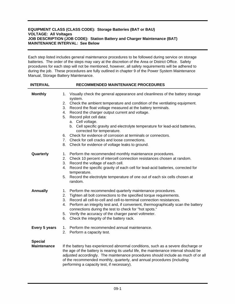
EQUIPMENT CLASS (CLASS CODE): Storage Batteries (BAT or BAU)VOLTAGE: All VoltagesJOB DESCRIPTION (JOB CODE): Station Battery and Charger Maintenance (BAT)MAINTENANCE INTERVAL: See Below
Each step listed includes general maintenance procedures to be followed during service on storagebatteries. The order of the steps may vary at the discretion of the Area or District Office. Safetyprocedures for each step will not be mentioned, however, all safety requirements will be adhered toduring the job. These procedures are fully outlined in chapter 9 of the Power System MaintenanceManual, Storage Battery Maintenance.
INTERVAL RECOMMENDED MAINTENANCE PROCEDURES
Monthly 1. Visually check the general appearance and cleanliness of the battery storage system.
2. Check the ambient temperature and condition of the ventilating equipment.3. Record the float voltage measured at the battery terminals.4. Record the charger output current and voltage.5. Record pilot cell data:
a. Cell voltage.b. Cell specific gravity and electrolyte temperature for lead-acid batteries,
corrected for temperature.6. Check for evidence of corrosion at terminals or connectors.7. Check for cell cracks and loose connections.8. Check for evidence of voltage leaks to ground.
Quarterly 1. Perform the recommended monthly maintenance procedures.2. Check 10 percent of intercell connection resistances chosen at random.3. Record the voltage of each cell.4. Record the specific gravity of each cell for lead-acid batteries, corrected for
temperature.5. Record the electrolyte temperature of one out of each six cells chosen at
random.
Annually 1. Perform the recommended quarterly maintenance procedures.2. Tighten all bolt connections to the specified torque requirements.3. Record all cell-to-cell and cell-to-terminal connection resistances.4. Perform an integrity test and, if convenient, thermographically scan the battery
connections during the test to check for "hot spots."5. Verify the accuracy of the charger panel voltmeter.6. Check the integrity of the battery rack.
Every 5 years 1. Perform the recommended annual maintenance.2. Perform a capacity test.
SpecialMaintenance If the battery has experienced abnormal conditions, such as a severe discharge or
the age of the battery is nearing its useful life, the maintenance interval should be adjusted accordingly. The maintenance procedures should include as much of or all of the recommended monthly, quarterly, and annual procedures (including performing a capacity test, if necessary).
09-1
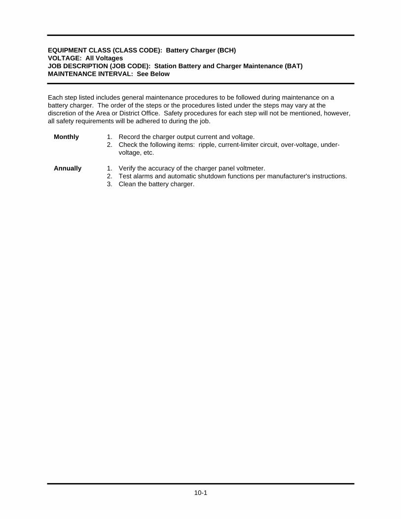
EQUIPMENT CLASS (CLASS CODE): Battery Charger (BCH)VOLTAGE: All VoltagesJOB DESCRIPTION (JOB CODE): Station Battery and Charger Maintenance (BAT)MAINTENANCE INTERVAL: See Below
Each step listed includes general maintenance procedures to be followed during maintenance on abattery charger. The order of the steps or the procedures listed under the steps may vary at thediscretion of the Area or District Office. Safety procedures for each step will not be mentioned, however,all safety requirements will be adhered to during the job.
Monthly 1. Record the charger output current and voltage.2. Check the following items: ripple, current-limiter circuit, over-voltage, under-
voltage, etc.
Annually 1. Verify the accuracy of the charger panel voltmeter.2. Test alarms and automatic shutdown functions per manufacturer's instructions.3. Clean the battery charger.
10-1