Embed Size (px)
Citation preview

Substation Buildings
Document Number: 1-11-FR-14
VERSION 1.0 June 2018

This functional requirement document is in line with the organisation's 1-11-ACS-14 Substation Buildings Asset Class Strategy
Intellectual property rights and disclaimer
This document is published in accordance with the requirements of Chapter 5 of the National Electricity Rules (NER). It is a functional requirement document only and is not intended to contain any comprehensive or project specific designs, specifications or other information. Whilst care has been taken to ensure that the contents of this document are accurate, ElectraNet Pty Limited (ElectraNet) does not represent or warrant that the information contained in this document is complete, accurate or adequate in any respect. ElectraNet reserves the right to amend this document at any time without notice to any person.
The user must carefully examine and check the information contained in this document and carry out its own independent technical and legal assessment and due diligence to ensure that the information in this document is used appropriately and that in doing so, all requirements (including requirements at law) are satisfied. For the avoidance of any doubt, the publication of this document does not limit or detract from the user’s obligations at law, and does not and will not give rise to any claim (including, without limitation, in contract, tort, equity, under statute or otherwise) against ElectraNet or any of its ‘Associates’ (as that term is defined in Corporations Act 2001 (Cth)).
All intellectual property rights (including without limitation any copyright, patents, logos, designs, circuit layouts, trademarks, moral rights and know how) in the whole and every part of this document are owned by or licenced to ElectraNet. Except as expressly provided in Chapter 5 of the NER or with the prior written consent of ElectraNet, the contents of this document cannot be used, transferred, copied, modified or reproduced in whole or in part in any manner or form or in any media.
© ElectraNet Pty Limited. All rights reserved.

Substation Buildings l Document No: 1-11-FR-14
Security Classification: Public WHEN PRINTED THIS DOCUMENT IS UNCONTROLLED
Date: June 2018
Version: 1.0 ©ElectraNet Pty Limited 2018 – all rights reserved
Page 3 of 48
Contents
1. Definitions .................................................................................................................. 6
2. Purpose and Scope ................................................................................................... 8
3. Referenced Documents ............................................................................................ 9
4. Substation Buildings............................................................................................... 11 4.1 Building General ..........................................................................................................11
4.1.1 Introduction .............................................................................................................11 4.1.2 Forms of Substation Buildings ................................................................................11 4.1.3 Structural Design ....................................................................................................12 4.1.4 Drawings and Information to be Submitted to ElectraNet ........................................13 4.1.5 Building Rules Certification by Private Certifier .......................................................13 4.1.6 Acceptance of Design and Drawings ......................................................................13
4.2 Transportable Buildings ..............................................................................................13 4.2.1 Introduction .............................................................................................................13 4.2.2 Structural Design ....................................................................................................14 4.2.3 Footing Design .......................................................................................................14 4.2.4 Base Frame Chassis ..............................................................................................14 4.2.5 Floor .......................................................................................................................14 4.2.6 Walls and Roof .......................................................................................................15 4.2.7 Access Stairs ..........................................................................................................16 4.2.8 Factory Acceptance Test or Inspection ...................................................................16
4.3 Precast Concrete Building ..........................................................................................16 4.3.1 Introduction .............................................................................................................16 4.3.2 Structural Design ....................................................................................................16 4.3.3 Footing Design .......................................................................................................17 4.3.4 Manufacture of Precast Units ..................................................................................17 4.3.5 Marking of Precast Units .........................................................................................17 4.3.6 Precast Tolerances .................................................................................................17 4.3.7 Precast Finish .........................................................................................................17 4.3.8 Handling Precast Units ...........................................................................................18 4.3.9 Lifting Devices ........................................................................................................18
4.4 Masonry Blockwork Building ......................................................................................19 4.4.1 Preparation .............................................................................................................19 4.4.2 Blockwork Materials ................................................................................................19 4.4.3 Masonry Block Workmanship..................................................................................20
4.5 Pavement around Building ..........................................................................................22 4.5.1 General ...................................................................................................................22 4.5.2 Subgrade ................................................................................................................22 4.5.3 Herbicide ................................................................................................................23 4.5.4 Pavement Material ..................................................................................................23 4.5.5 Tolerances ..............................................................................................................23
4.6 Other Common Requirements for All Types of Building ..........................................24 4.6.1 External Entry/Exit Doors ........................................................................................24 4.6.2 Exit Signs ...............................................................................................................24 4.6.3 Electrical - General .................................................................................................25 4.6.4 Air Conditioning ......................................................................................................25 4.6.5 Lighting ...................................................................................................................26 4.6.6 Cable Ladder and Risers ........................................................................................27 4.6.7 Intruder Alarms .......................................................................................................27

Substation Buildings l Document No: 1-11-FR-14
Security Classification: Public WHEN PRINTED THIS DOCUMENT IS UNCONTROLLED
Date: June 2018
Version: 1.0 ©ElectraNet Pty Limited 2018 – all rights reserved
Page 4 of 48
4.6.8 Security ..................................................................................................................28 4.6.9 Fire Extinguishers ...................................................................................................28
4.7 Site Water Supply ........................................................................................................28
5. Control Building ...................................................................................................... 30 5.1 General .........................................................................................................................30 5.2 Floor .............................................................................................................................30 5.3 Electrical .......................................................................................................................30
5.3.1 General ...................................................................................................................30 5.3.2 AC Distribution Board .............................................................................................30 5.3.3 DC Power for Control Buildings ..............................................................................31 5.3.4 Earthing / Bonding ..................................................................................................31
5.4 Air Conditioning ...........................................................................................................32 5.5 Fire Alarm Services .....................................................................................................32
5.5.1 General ...................................................................................................................32 5.5.2 Design Drawings.....................................................................................................32 5.5.3 Inspection of the Works (for Transportable Buildings) .............................................32 5.5.4 Detectors ................................................................................................................32 5.5.5 Access ....................................................................................................................33 5.5.6 Alarm Bell ...............................................................................................................33 5.5.7 Fire Indicator Panel (FIP) ........................................................................................33 5.5.8 DC Power supply ....................................................................................................33 5.5.9 Connection to Substation Data System ...................................................................33 5.5.10 Location Diagram ....................................................................................................33 5.5.11 Radio Interference ..................................................................................................33 5.5.12 Air Conditioning Shutdown ......................................................................................33 5.5.13 Conduits and Wiring ...............................................................................................34 5.5.14 Maintenance Manuals .............................................................................................34 5.5.15 Spares ....................................................................................................................34 5.5.16 Tests .......................................................................................................................34 5.5.17 Tests and Service during the Defects Liability Period .............................................34
5.6 Diagram Board .............................................................................................................34 5.7 Furniture .......................................................................................................................34
6. Amenities Building .................................................................................................. 36 6.1 General .........................................................................................................................36 6.2 Drainage .......................................................................................................................36
6.2.1 General ...................................................................................................................36 6.2.2 Drainage Layout Drawings ......................................................................................36 6.2.3 Septic System .........................................................................................................37 6.2.4 Testing ....................................................................................................................37
6.3 Plumbing ......................................................................................................................37 6.3.1 Regulations .............................................................................................................37 6.3.2 Access ....................................................................................................................38 6.3.3 Testing ....................................................................................................................38 6.3.4 Drawings for Water Supply .....................................................................................38 6.3.5 Workmanship ..........................................................................................................38 6.3.6 Connection from Council Mains ..............................................................................39 6.3.7 External Reticulation ...............................................................................................40 6.3.8 Wastes ...................................................................................................................40
6.4 Electrical .......................................................................................................................40 6.5 Air Conditioning ...........................................................................................................40 6.6 Fittings and Fixtures ....................................................................................................41
6.6.1 General ...................................................................................................................41

Substation Buildings l Document No: 1-11-FR-14
Security Classification: Public WHEN PRINTED THIS DOCUMENT IS UNCONTROLLED
Date: June 2018
Version: 1.0 ©ElectraNet Pty Limited 2018 – all rights reserved
Page 5 of 48
6.6.2 Schedule of Fixtures and Fittings ............................................................................41 6.6.3 Hardware ................................................................................................................41 6.6.4 Mirror ......................................................................................................................41 6.6.5 Furniture .................................................................................................................42 6.6.6 Diagram Board .......................................................................................................42 6.6.7 Substation Padlock and Key Boards .......................................................................42
6.7 Fire Alarm Services .....................................................................................................43
7. Shed ......................................................................................................................... 44
7.1.1 General ...................................................................................................................44 7.1.2 Shed Electrical ........................................................................................................44 7.1.3 Fire Services ...........................................................................................................44 7.1.4 Extinguisher ............................................................................................................44 7.1.5 Furniture .................................................................................................................44
8. Brownfield Buildings............................................................................................... 45 8.1 General .........................................................................................................................45 8.2 Clearance and Equipment Spacing in Buildings .......................................................45
Substation Buildings l Document No: 1-11-FR-14
Security Classification: Public WHEN PRINTED THIS DOCUMENT IS UNCONTROLLED
Date: June 2018
Version: 1.0 ©ElectraNet Pty Limited 2018 – all rights reserved
Page 6 of 48
1. Definitions
In this document the following words and expressions will have the following meanings:
Item Meaning
AC Alternating Current.
AS Australian Standard, as publication by Standards Australia (Standards Association of Australia).
BTU British Thermal Unit.
Contractor A contractor engaged by ElectraNet or a Customer (including a third party IUSA provider engaged by a Customer or any contractor engaged by such third party IUSA provider) to perform any design, construction or related services in relation to assets or infrastructure which are connected, or to be connected, to ElectraNet’s transmission network
Customer A party who wants to establish or modify a connection to ElectraNet’s transmission network but does not include a third party IUSA provider
DC Direct Current.
DPTI Department of Planning, Transport and Infrastructure.
EHV Extra High Voltage.
ELCB Earth Leakage Circuit Breaker
FIP Fire Indicator Panel.
GIS Gas Insulated Switchgear.
GPO General Purpose Outlet.
LED Light Emitting Diode.
low voltage or LV Nominal voltage exceeding 50 volts alternating current or 120 volts direct current, but not exceeding 1000 volts alternating current or 1500 volts direct current.
MDD Maximum Dry Density.
NATA National Association of Testing Authorities Australia.
PVC Polyvinyl Chloride.
RCD Residual Current Device
SAA SAA Approvals is accredited by the Joint Accreditation Service of Australia and New Zealand (JAS-ANZ) as a third party certification body to issue of Certificates of Approval for declared and non-declared electrical equipment that has proven to comply with the safety requirements of the applicable Australian Standard.
SCADA Supervisory Control And Data Acquisition.
SSD System Switching Diagram.
Standard Drawing A drawing developed by ElectraNet as a complete design to be used for construction.
Standard Drawings are not intended to be revised or renumbered.

Substation Buildings l Document No: 1-11-FR-14
Security Classification: Public WHEN PRINTED THIS DOCUMENT IS UNCONTROLLED
Date: June 2018
Version: 1.0 ©ElectraNet Pty Limited 2018 – all rights reserved
Page 7 of 48
Item Meaning
Template Drawing A drawing developed by ElectraNet as the basis for design.
Template Drawings are intended to be revised and renumbered as required to complete the design.
third party IUSA Has the same meaning as defined in the National Electricity Rules
TPS Thermoplastic-sheathed

Substation Buildings l Document No: 1-11-FR-14
Security Classification: Public WHEN PRINTED THIS DOCUMENT IS UNCONTROLLED
Date: June 2018
Version: 1.0 ©ElectraNet Pty Limited 2018 – all rights reserved
Page 8 of 48
2. Purpose and Scope
The purpose of this document is to describe the functional requirements for Substation Buildings and their integration into the overall substation requirements.
The building technologies of Transportable, Precast Concrete and Masonry are presented with site specific documentation discussing which may be most appropriate for the Control and Amenities buildings. Sections on sheds and brownfield buildings are also included.
This document is mainly aimed at providing the functional requirements for buildings covering protection, control, amenities, telecommunications (subject to building form) and storage functions.
This document does not specifically cover the requirements for buildings to be used for indoor Gas Insulated Switchgear (GIS), Static Var Compensator protection and control and metal clad switchgear which can be used for applications up to and including 33 kV.
This document also covers the requirements for establishing a site water supply.

Substation Buildings l Document No: 1-11-FR-14
Security Classification: Public WHEN PRINTED THIS DOCUMENT IS UNCONTROLLED
Date: June 2018
Version: 1.0 ©ElectraNet Pty Limited 2018 – all rights reserved
Page 9 of 48
3. Referenced Documents
The table below lists applicable legislations, standards, referenced documents:
Legislation
SAEA Electricity Act 1996 (SA)
SAER South Australia Electricity (General) Regulations 2012 (SA) under the SAEA
NER National Electricity Rules
ETC Electricity Transmission Code TC/08
SAA HB59:1994 Ergonomics - The human factor A practical approach to work systems design
South Australian Development Act 1993
Standards
AS/NZS 1170.0:2002 Structural design actions - General principles
AS/NZS 1170.2:2011 (R2016) Structural design actions - Wind actions
AS/NZS 1170.4:2007 Structural design actions - Earthquake actions in Australia
AS/NZS 1214:2016 Hot–dip galvanized coatings on threaded fasteners (ISO metric course thread series) (ISO 19684:2004, MOD)
AS 1289.5.1.1:2017 Methods of testing soils for engineering purposes - Soil compaction and density tests - Determination of the dry density / moisture content relation of a soil using standard compactive effort
AS/NZS 1547:2012 On-site domestic wastewater management
AS/NZS 1554.1 :2014 Structural steel welding - Welding of steel structures
AS 1565:1996 Copper and copper alloys - Ingots and castings
AS 2067 :2016 Substations and high voltage installations exceeding 1 kV a.c.
AS 2419.1 :2017 Fire hydrant installation – System design, installation and commissioning
AS 2870 :2011 Residential slabs and footing construction
AS/NZS 3000:2007 Electrical Installations (known as the Australian/New Zealand Wiring Rules)
AS 3600:2009 + Amdt 1:2010 + Amdt 2:2013
Concrete structures
AS 3610:1995 Formwork for concrete
AS 3700 :2011 Masonry structures
AS 3798:2007 + Amdt 1:2008 Guidelines on earthworks for commercial and residential developments
AS 3850.1:2015 Prefabricated concrete elements - General requirements
AS 3850.2:2015 Prefabricated concrete elements - Building construction
AS 4100:1998 (R2016)/Amdt 1-2012
Steel Structures
AS/NZS 4671:2001 Steel reinforcing materials

Substation Buildings l Document No: 1-11-FR-14
Security Classification: Public WHEN PRINTED THIS DOCUMENT IS UNCONTROLLED
Date: June 2018
Version: 1.0 ©ElectraNet Pty Limited 2018 – all rights reserved
Page 10 of 48
AS/NZS 4680 :2006 Hot–dip galvanized (zinc) coatings on fabricated ferrous articles
ElectraNet’s Documentation
1-11-FR-03 Electronic Security
1-11-FR-09 Substation Configuration
1-11-FR-17 Substation Support Structures and Footings
1-10-ADM-01 Telecommunications Buildings
1-11-ADM-14 Substation Buildings

Substation Buildings l Document No: 1-11-FR-14
Security Classification: Public WHEN PRINTED THIS DOCUMENT IS UNCONTROLLED
Date: June 2018
Version: 1.0 ©ElectraNet Pty Limited 2018 – all rights reserved
Page 11 of 48
4. Substation Buildings
4.1 Building General
4.1.1 Introduction
4.1.1.1 This document describes the functional requirements for the use of three types of buildings covering the use of transportable buildings and permanent buildings, i.e. those which can only be constructed on site.
4.1.1.2 Typically when transportable buildings are nominated for a specific project the substation design needs to cater for multiple buildings throughout the substation.
4.1.1.3 Typically transportable control buildings will be sized to accommodate the protection and control functions for a maximum of nine switching bays.
4.1.1.4 Typically when permanent buildings are nominated for a specific project the substation design will need to cater for one or two buildings.
4.1.1.5 Permanent buildings will be multipurpose with dedicated rooms allocated for various functions described in this document.
4.1.1.6 Permanent buildings will typically have to be sized for the ultimate requirements of the substation and will need to have space allocation to allow for equipment replacement over the design life of the substation, in such a manner that minimises outage times.
4.1.1.7 Document 1-11-FR-09 covering substation configuration will provide more detail on determining the number and placement of buildings within substation.
4.1.1.8 The design life for transportable buildings must be 25 years.
4.1.1.9 The design life for a permanent building must be 50 years.
4.1.1.10 Buildings under the cover of this document must always have a minimum of entry/exit doors, and in multi-room buildings each room must have two independent entry/exit points.
4.1.1.11 All buildings including cable, duct and trench entries must be appropriately sealed to prevent vermin entry.
4.1.2 Forms of Substation Buildings
4.1.2.1 Substation buildings must be constructed as:
a) Transportable buildings - steel frames with colorbond steel sheeting walls;
b) Precast concrete buildings; or
c) Masonry Blockwork Buildings.

Substation Buildings l Document No: 1-11-FR-14
Security Classification: Public WHEN PRINTED THIS DOCUMENT IS UNCONTROLLED
Date: June 2018
Version: 1.0 ©ElectraNet Pty Limited 2018 – all rights reserved
Page 12 of 48
4.1.2.2 The layout of the precast concrete and the masonry blockwork type buildings must include a well demarcated battery room, a well demarcated LV AC Switchboard room to contain the AC changeover board and main distribution board for the substation as well as a separate amenities area. This requirement is waived for transportable type buildings because of limitations imposed by the need to transport them to site via national highways.
4.1.2.3 Windows are prohibited unless specifically requested via the project engineering contract specifications.
4.1.2.4 All roof sheeting and building cladding must be fixed with anti-tamper fixings.
4.1.2.5 All entry/exit doors to substation buildings must open to the outside.
4.1.2.6 Further requirements specific to each form of building construction are provided in succeeding clauses.
4.1.2.7 This document does not cover the detailed requirements for telecommunications buildings. However, this document does cover the general requirements that would be applicable to transportable telecommunications buildings. Refer to document 1-10-ADM-01 for telecommunications building detailed requirements.
4.1.3 Structural Design
4.1.3.1 Wind loading for each building, and the associated footings, must be assessed in accordance with the requirements of AS 2067:2016 clause 2.3 which makes reference to the AS/NZS 1170 series of Standards.
4.1.3.2 The wind loading annual probability of exceedance for ultimate limit states must be 1/1000 based on a design working life of 50 years and an importance level of 3 in accordance with Appendix F of AS/NZS 1170.0:2002, irrespective of building type.
4.1.3.3 The Terrain Category must be 2 unless indicated otherwise in site specific documentation.
4.1.3.4 The topographic, direction, shielding and terrain wind multipliers must be site specific and must be derived in accordance with AS/NZS 1170.2.
4.1.3.5 Equipment loading considerations must be in accordance with AS 2067:2016 clause 2.3.
4.1.3.6 The floor and support system must be designed for the actual equipment loadings with a minimum requirement of:
d) A dead load of 5 kPa for electrical panels;
e) A dead load of 15 kPa for battery areas;
f) Should metal clad switchboard be installed the floor support system will need to cater for the standing load of the switchboard and any reaction forces during breaker operation; and
g) A live load of 4 kPa plus a point load of 1.8 kN at any point over the remainder of the floor area (including Amenities Building).

Substation Buildings l Document No: 1-11-FR-14
Security Classification: Public WHEN PRINTED THIS DOCUMENT IS UNCONTROLLED
Date: June 2018
Version: 1.0 ©ElectraNet Pty Limited 2018 – all rights reserved
Page 13 of 48
4.1.3.7 Earthquake loads must be assessed in accordance with AS 2016:2016 clause 2.3 which makes reference to AS 1170.4.
4.1.3.8 The earthquake loading annual probability of exceedance for ultimate limit states must be 1/1000 based on a design working life of 50 years and an importance level of 3.
4.1.3.9 Other loads must be assessed in accordance with the AS/NZS 1170 series of Standards.
4.1.3.10 All of the above Structural Design requirements also apply to dedicated telecommunications buildings irrespective of their location.
4.1.4 Drawings and Information to be Submitted to ElectraNet
4.1.4.1 The Contractor must submit all of the following information, in the specified time frame prior to fabrication or construction of the buildings.
a) Structural Engineer’s Certificate;;
b) Civil, Structural and Architectural Engineering Drawings;
c) Ancillary Service Drawings and manuals including fire and intruder alarm services;
d) Septic or Sewerage drainage design and drawings; and
e) All remaining drawings required by the Local Council to obtain Building Approval for the installation of the buildings.
4.1.5 Building Rules Certification by Private Certifier
4.1.5.1 The Contractor must submit the necessary documentation and drawings for all works requiring building rules certification prior to construction in accordance with 1-11-FR-17 Substation Support Structures and Footings.
4.1.6 Acceptance of Design and Drawings
4.1.6.1 In accordance with 1-11-FR-17 Substation Support Structures and Footings all designs for foundations and structural elements including design certificates produced for the work to be carried out under this specification must be subject to review and acceptance by the Principal.
4.2 Transportable Buildings
4.2.1 Introduction
4.2.1.1 Unless indicated in site specific documentation, transportable buildings must be single-storey, steel framed, insulated construction using Colorbond pre-painted steel sheeting to internal and external walls and roof.
4.2.1.2 Apart from telecommunications buildings, unless indicated in site specific documentation the transportable building must be elevated at least 500 mm above the ground.

Substation Buildings l Document No: 1-11-FR-14
Security Classification: Public WHEN PRINTED THIS DOCUMENT IS UNCONTROLLED
Date: June 2018
Version: 1.0 ©ElectraNet Pty Limited 2018 – all rights reserved
Page 14 of 48
4.2.1.3 Transportable telecommunications buildings must are to be directly mounted at ground level on a suitably compacted area.
4.2.1.4 ElectraNet has Template Drawings identifying key features to be provided with and within the various transportable buildings.
4.2.2 Structural Design
4.2.2.1 Steel structure strength must be in accordance with AS 4100.
4.2.2.2 Beam deflections and foundation differential movements must be limited to within acceptable limits set in the design standards to ensure that the operation of doors and contact based intruder or other alarm systems is not compromised.
4.2.3 Footing Design
4.2.3.1 The footing design must be in accordance with AS 3600 and must incorporate the recommendations of the site Geotechnical Investigation Report.
4.2.3.2 Transportable telecommunications buildings do not require concrete footings.
4.2.3.3 The design must consider the interface with structure anchorages and cast-in holding down bolts.
4.2.4 Base Frame Chassis
4.2.4.1 The design and fabrication of the base frame chassis must take into account the length and depth of local galvanizing baths so the elements can be successfully galvanized.
4.2.4.2 The structural base frame of the buildings must consist of at least two main steel bearers running the entire length of the building.
4.2.4.3 Steel joists must be provided at regular intervals and be welded or bolted to the steel base.
4.2.4.4 All welds must be in accordance with AS 1554.1.
4.2.4.5 All steelwork must be hot-dip galvanized to AS 4680 after fabrication to achieve the specified design life.
4.2.4.6 The Contractor must supply all fittings and assembly requirements to install the building on the footings.
4.2.4.7 Refer to document 1-10-ADM-01 for the requirements for the telecommunications buildings.
4.2.5 Floor
4.2.5.1 The floor must be a minimum 15 mm compressed fibre-cement and be securely fixed to the joists to provide a strong and rigid platform.

Substation Buildings l Document No: 1-11-FR-14
Security Classification: Public WHEN PRINTED THIS DOCUMENT IS UNCONTROLLED
Date: June 2018
Version: 1.0 ©ElectraNet Pty Limited 2018 – all rights reserved
Page 15 of 48
4.2.5.2 Alternatively, a flooring system, which provides equivalent strength to the fibre-cement system and equivalent fire protection from below, may be considered.
4.2.5.3 The internal floor must be covered with seam welded heavy-duty vinyl sheet with a 100 mm skirting.
4.2.5.4 Refer to document 1-10-ADM-01 for the requirements for the telecommunications buildings.
4.2.6 Walls and Roof
4.2.6.1 The walls and roof must be galvanized steel stud and plate construction.
4.2.6.2 The roof slope must be at least 5 degree to permit free draining of water.
4.2.6.3 The walls must be insulated with 50 mm fibreglass insulation and the roof with 50 mm thick fibreglass insulation having Sisalation 453 bonded to the insulation.
4.2.6.4 External walls must have a ‘Colorbond’ pre-painted Zincalume steel finish and may be lightly profiled.
4.2.6.5 All joins of wall panels must be formed in such a way as to prevent the ingress of moisture and dust.
4.2.6.6 Panel to panel joins must provide a tight, strong and rigid finish.
4.2.6.7 Internal walls and ceiling must be lined with MESA profile ribbed cladding.
4.2.6.8 The roof must have a ‘Colorbond’ pre-painted Zincalume steel finish in continuous lengths from ridge to gutter.
4.2.6.9 The colour of the building’s exterior Colorbond cladding must be Colorbond Paperbark.
4.2.6.10 All work must be erected plumb, square and in proper alignment and relationship with the building framing.
4.2.6.11 All flashings must be steel accessory feed in Colorbond all suitably scribed, folded, sealed and lapped as necessary.
4.2.6.12 Minimum laps in pitched areas to be 100 mm and in horizontal areas to be 150 mm.
4.2.6.13 All horizontal laps must be sealed with two beads of Selleys silicone sealant 780.
4.2.6.14 Sealant at stop ends, around drops and penetrations must be Selleys silicone sealant 780 to provide a waterproof installation.
4.2.6.15 The Contractor must provide and fix ‘Colorbond’ gutters for the full length of the external wall(s) of the building and supply and install “Great Barrier Leaf” or approved equivalent leaf guard.

Substation Buildings l Document No: 1-11-FR-14
Security Classification: Public WHEN PRINTED THIS DOCUMENT IS UNCONTROLLED
Date: June 2018
Version: 1.0 ©ElectraNet Pty Limited 2018 – all rights reserved
Page 16 of 48
4.2.6.16 Downpipes and stormwater drainage must be provided by the Contractor to the Buildings in accordance with the requirements of the Local Authority.
4.2.6.17 Downpipes must direct water into the subsurface stormwater drainage system or to the rainwater tank, as appropriate.
4.2.6.18 Full-length weather hoods must be provided above each doorway.
4.2.6.19 All weather hoods must be formed from ‘Colorbond’ steel and must project a minimum 600mm from the point of attachment.
4.2.6.20 All external fixings must be stainless steel or galvanized to meet the design life of the building.
4.2.6.21 Refer to document 1-10-ADM-01 for the requirements for the telecommunications buildings. Gutters and downpipes are not required for telecommuncations buildings.
4.2.7 Access Stairs
4.2.7.1 Access stairs must be supplied and be so designed that they can be installed after installation of the building.
4.2.7.2 All access steelwork must be hot-dip galvanized to AS/NZS 4680 after fabrication.
4.2.7.3 All access fixings must also be galvanized in accordance with AS/NZS 1214.
4.2.8 Factory Acceptance Test or Inspection
4.2.8.1 After fabrication and prior to the building being taken to site, the ElectraNet will conduct a factory acceptance inspection.
4.2.8.2 For the period of the inspection, the Contractor will provide an electrical supply connected to the building electrical system.
4.2.8.3 At least one week’s notice is to be given to the Principal to arrange a mutually agreeable time for the inspection.
4.2.8.4 All items deemed to be unsatisfactorily completed will be noted and remedial works will be undertaken prior to the building being delivered to site.
4.3 Precast Concrete Building
4.3.1 Introduction
4.3.1.1 Unless indicated in site specific documentation, precast concrete buildings must be single-storey with precast concrete walls and a steel support structure for a Colorbond pre-painted steel sheeting roof.
4.3.2 Structural Design
4.3.2.1 Precast concrete panels or units must be designed in accordance with AS 3600.

Substation Buildings l Document No: 1-11-FR-14
Security Classification: Public WHEN PRINTED THIS DOCUMENT IS UNCONTROLLED
Date: June 2018
Version: 1.0 ©ElectraNet Pty Limited 2018 – all rights reserved
Page 17 of 48
4.3.2.2 Roof steelwork must be designed in accordance with AS 4100.
4.3.2.3 Roofing system must be Bondor ‘metecnospan’ insulated roofing panels, with a nominal width of 100 mm.
4.3.2.4 Beam deflections and foundation differential movements must be limited to within acceptable limits set in the design standards to ensure that the operation of doors and contact based intruder or other alarm systems is not compromised.
4.3.3 Footing Design
4.3.3.1 The footing design must be in accordance AS 3600 and must incorporate the recommendations of the site Geotechnical Investigation Report.
4.3.3.2 The foundation for the precast building must limit differential movement and settlement according to the geotechnical assessment.
4.3.4 Manufacture of Precast Units
4.3.4.1 Formwork used for precast concrete panels must comply with AS 3610.
4.3.4.2 The manufacture and installation of precast concrete panels must comply with AS 3850.1 and AS 3850.2.
4.3.4.3 Concrete of precast units must be grade N40.
4.3.5 Marking of Precast Units
The Contractor must identify precast units by marks which:
a) Remain legible until after the unit has been fixed in place;
b) Are not visible in the completed structure;
c) Show the date of casting; and
d) Show the correct orientation of the unit.
4.3.6 Precast Tolerances
4.3.6.1 Precast concrete units must comply with acceptable deviations outlined in the most stringent of Table 3.4.3 of AS 3610 or Table 2.5 of AS 3850.2.
4.3.6.2 Tolerances for fixings and embedded components in precast concrete units must be in accordance with the most stringent of Table 5.3.1 of AS 3610 or Table 2.6 of AS 3850.2.
4.3.7 Precast Finish
4.3.7.1 External finish must be “Natural” with “Light Exposure Sand blast”. Internal finish must be Class 2.
4.3.7.2 Class 2 surface finish required for tolerances in accordance with Table 3.4.2 of AS 3610.

Substation Buildings l Document No: 1-11-FR-14
Security Classification: Public WHEN PRINTED THIS DOCUMENT IS UNCONTROLLED
Date: June 2018
Version: 1.0 ©ElectraNet Pty Limited 2018 – all rights reserved
Page 18 of 48
4.3.7.3 Site specific documentation will confirm if any in painting of internal walls or special surface finishes will be needed on the floors.
4.3.8 Handling Precast Units
4.3.8.1 The National code of practice for precast, tilt-up and concrete elements in building construction (2008) must be referred to for guidance on handling precast concrete elements.
4.3.8.2 Precast concrete wall panels must be transported in accordance with local traffic regulations, erected as discrete elements and temporarily braced securely and accurately in their final positions in accordance with AS 3850.2, then roof steelwork erected and completed before the temporary bracing is removed.
4.3.8.3 Components and materials, including fasteners, braces, shims, jointing strips, sealant, flashings, grout and mortar, must be provided by the Contractor as appropriate.
4.3.8.4 The precast units must not be lifted or supported at points other than designation points.
4.3.8.5 The Contractor must use handling methods which do not overstress, warp or damage the units.
4.3.8.6 No other work can proceed in the area of temporary bracing until the erection of all precast concrete panels and steel have been completed.
4.3.8.7 Chemical anchors are not permitted to be used as temporary bracing.
4.3.8.8 Temporary attachments must only be removed after erection of the structure. The Contractor must seal or otherwise make good residual recesses.
4.3.8.9 The Contractor must protect precast concrete units against staining, discolouration and damage.
4.3.8.10 All repairs should be carried out in accordance with the manufacturer’s Quality Plan, Work Method Statements and as agreed by ElectraNet.
4.3.9 Lifting Devices
4.3.9.1 Each lifting device must be designed for a working load at least 1.65 times the maximum calculated static load at that point and an ultimate load of 4 times the maximum static load.
4.3.9.2 Lifting attachments, holes and other temporary fixings for handling purposes must not be placed on visible faces of units. Recess lifting attachments such as ferrules, or other types of cast-in fixings, and provide plugs for sealing.

Substation Buildings l Document No: 1-11-FR-14
Security Classification: Public WHEN PRINTED THIS DOCUMENT IS UNCONTROLLED
Date: June 2018
Version: 1.0 ©ElectraNet Pty Limited 2018 – all rights reserved
Page 19 of 48
4.4 Masonry Blockwork Building
4.4.1 Preparation
4.4.1.1 The use of masonry blockwork at ElectraNet substations is increasingly diminishing due to the use of prefabricated buildings. However, in built up areas and city locations, planning permission conditions might require the use of masonry blockwork.
4.4.1.2 In such instances, the Contractor must construct all blockwork in accordance with the requirements of AS 3700.
4.4.1.3 The Contractor must, prior to commencing block-laying, survey all foundations for blockwork so as to ensure that the lines and levels of the foundations and any reinforcing bars are correct and that the specified bond can be achieved.
4.4.1.4 The footing design must be in accordance AS 3600 and must incorporate the recommendations of the site Geotechnical Investigation Report.
4.4.1.5 In the event that blockwork foundations are incorrect in line or level, or that specified bonding cannot be achieved, the Contractor must immediately so advise ElectraNet and must not commence block-laying until approved to do so by ElectraNet.
4.4.1.6 The Contractor must clean all blockwork foundations using brooming, water-jetting, degreasing solvents, wire brushing, scabbling and other methods as necessary so as to remove all mud, soil, grease, form oil, concrete laitance, rust and other detrimental materials.
4.4.1.7 The Contractor must employ only skilled, experienced tradesmen to carry out masonry block-laying.
4.4.2 Blockwork Materials
4.4.2.1 All blockwork materials must comply with Section 11 of AS 3700.
4.4.2.2 Concrete masonry blocks must not be less than Class 15 MPa.
4.4.2.3 The Contractor must not use blocks that are cracked, chipped, crumbling, malformed, discoloured, pre-used, or otherwise of inferior quality.
4.4.2.4 Fine aggregates for use in mortar must be uniformly graded to the approval of ElectraNet and must satisfy the following sieve grading:
Table 4-1 Sieve Gradings for Fine Aggregates for use in mortar
Sieve Aperture % By Weight Passing Sieve
4.75 mm 100
2.36 mm 99 – 100
75 microns 0 – 10
4.4.2.5 Fine aggregates for use in mortar must consist of clean, sharp, washed sand, such as plasterer's sand.

Substation Buildings l Document No: 1-11-FR-14
Security Classification: Public WHEN PRINTED THIS DOCUMENT IS UNCONTROLLED
Date: June 2018
Version: 1.0 ©ElectraNet Pty Limited 2018 – all rights reserved
Page 20 of 48
4.4.2.6 The Contractor must not use detergents or plasticising additives in mortar.
4.4.2.7 Unless otherwise shown on the drawings mortar used in the construction of blockwork must be classification M4 in accordance with Section 11.4 of AS 3700 and mixed in the following proportions by volume:
Table 4-2 Mortar mixtures and proportions
Constituent Parts by Volume
Portland Cement to AS 3972 1
Hydrated Lime or Lime Putty 0 to 0.25
Sand 3
4.4.2.8 All mortar constituents must be accurately measured in suitable containers.
4.4.2.9 The use of shovels for measuring mortar constituents is not acceptable.
4.4.2.10 Mortar in which the specified proportions of all constituents have not been incorporated in an accurately measured and well-mixed manner must be liable to rejection together with any blockwork in which such mortar has been used.
4.4.2.11 Hand mixing or retempering of mortar will not be permitted.
4.4.2.12 Grout for use to fill cores in masonry blockwork must comply with Section 11.7 of AS 3700.
4.4.2.13 Aggregate must be rounded river gravel.
4.4.2.14 For reinforced masonry, grout must have a Portland cement content (excluding the mass of any supplementary cementitious materials like Fly Ash) of not less than 300kg/m3.
4.4.2.15 At least three weeks before grouting commences, the Contractor must supply to ElectraNet, for approval, documentation or certification that the materials to be used for all masonry blockwork, including mortar and grout, comply with AS 3700 and this Specification. A blockwork grout mix design must also be submitted where applicable.
4.4.2.16 Reinforcing for reinforced blockwork must comply with AS/NZS 4671.
4.4.2.17 All damp proof courses, flashings, weatherings, solid copings, sills, thresholds, lintels, wall ties, air bricks and vent faces for use in masonry blockwork must be in accordance with Section 4 of AS 3700.
4.4.3 Masonry Block Workmanship
4.4.3.1 Blockwork construction must be carried out in accordance with Section 12 of AS 3700, except that full mortar bedding must be used for all partially grouted blockwork.
4.4.3.2 The Contractor must protect all masonry blockwork materials in accordance with Sections 12.4, 12.9 and 12.10 of AS 3700.

Substation Buildings l Document No: 1-11-FR-14
Security Classification: Public WHEN PRINTED THIS DOCUMENT IS UNCONTROLLED
Date: June 2018
Version: 1.0 ©ElectraNet Pty Limited 2018 – all rights reserved
Page 21 of 48
4.4.3.3 The Contractor must build all blockwork true and plumb within the tolerances set out in Section 12.5 of AS 3700.
4.4.3.4 The Contractor must grout blockwork using immersion vibrators.
4.4.3.5 The Contractor must comply with Sections 11 and 12 of AS 3700 for all cavity walls, joint finishes, damp-proof courses, temporary bracing, protection during construction, and cleaning-down.
4.4.3.6 The Contractor must use special blocks with knock-out cleaning holes in the first course of all lifts of grouted blockwork walls.
4.4.3.7 The Contractor must rod off all mortar fins protruding into blockwork cores to be grouted, and must clean out and remove all mortar and rubbish from cores, prior to placing reinforcing.
4.4.3.8 The Contractor must not grout blockwork cores until at least two days after completion of laying.
4.4.3.9 In the event that a grouted hollow blockwork wall higher than 1.8 metres is to be constructed, the Contractor must carry out construction in 1.8 metre maximum height lifts and must not commence any new lift until the previous lift has been fully grouted.
4.4.3.10 The Contractor must thoroughly compact each lift of grout in blockwork cores using immersion vibrators, or by rodding when, in the opinion of ElectraNet, vibrators cannot be used.
4.4.3.11 Grout to fill cores in masonry blockwork must be placed at a workability slump appropriate for the work to be undertaken and no water must be added to any grout mix after the grout has left the batching plant.
4.4.3.12 The grout must be sampled, tested and evaluated for compressive strength in accordance with the requirements for concrete given in Section 17.1 of AS 3600, except the testing frequency must be as follows:
Table 4-3 – Grout testing frequency
Number of Batches Per Day Number of Samples
1 1
2 to 5 2
6 to 10 3
11 to 20 4
For each additional 10 batches, one additional sample must be taken.
Each Sample must consist of not less than 2 test cylinders.
One (1) slump test must be taken from each truck.
Where more than one plant is involved, the concrete from each plant must be sampled separately in accordance with this Clause.
4.4.3.13 All sampling (slump tests and test cylinders) must be carried out on site and the Contractor must supply the labour and materials required for taking slump tests and making the grout test cylinders.

Substation Buildings l Document No: 1-11-FR-14
Security Classification: Public WHEN PRINTED THIS DOCUMENT IS UNCONTROLLED
Date: June 2018
Version: 1.0 ©ElectraNet Pty Limited 2018 – all rights reserved
Page 22 of 48
4.4.3.14 The Contractor must at all times keep a detailed record of all test cylinders taken.
4.4.3.15 All test specimens must be cured and tested by an approved NATA registered laboratory.
4.4.3.16 The Contractor must inform ElectraNet of any test results indicating failure to meet the strength required not later than 14 days after testing.
4.4.3.17 Grout not meeting the requirements of this Specification must be liable to rejection.
4.4.3.18 All rejected grout must be removed and replaced by the Contractor.
4.4.3.19 Surfaces of grout exposed to the sun must be covered with hessian or other approved absorptive materials as soon as the grout has hardened and all surfaces, including formwork, covering materials and exposed grout must be kept continuously wet for a period of not less than seven days.
4.4.3.20 Polythene or other approved material may be used to surround all surfaces continuously for a period of seven days.
4.4.3.21 All grout test results must be attached to the Quality Assurance package to be submitted at the end of the works. Cylinder test records must include at least the following information:
a) Date of test;
b) Cylinder number;
c) Age of grout (days);
d) Diameter and length of cylinder;
e) Grout mass and density;
f) Capping details;
g) Crushing load; and
h) Grout strength.
4.5 Pavement around Building
4.5.1 General
4.5.1.1 Pavement is required around either concrete or masonry buildings, for the purpose of site drainage.
4.5.1.2 The pavement course must be constructed after construction of reinforced concrete footings, pipes and backfill.
4.5.2 Subgrade
4.5.2.1 The subgrade must consist of the upper surface of trench backfill, or that portion of the works located beneath the specified pavement layer, kerbs and gutters.

Substation Buildings l Document No: 1-11-FR-14
Security Classification: Public WHEN PRINTED THIS DOCUMENT IS UNCONTROLLED
Date: June 2018
Version: 1.0 ©ElectraNet Pty Limited 2018 – all rights reserved
Page 23 of 48
4.5.2.2 Following the installation of all underground services in the appropriate locations, the approved benching works must be trimmed off to allow for the required thicknesses, grades and levels of subsequent construction.
4.5.2.3 Subgrade must be compacted to a density of no less than 95% of its MDD in accordance with AS 1289.5.1.1 and AS 3798, to a minimum depth of 150mm using approved compaction equipment.
4.5.2.4 No subsequent construction must be placed until the subgrade has been compacted, graded and tested to the satisfaction of ElectraNet.
4.5.3 Herbicide
4.5.3.1 On the approved subgrade surface, the Contractor must supply and spray herbicide in accordance with the manufacturer's instructions.
4.5.3.2 The Contractor must notify ElectraNet two days prior to the completion of the formed surface.
4.5.3.3 Herbicide must not be applied in windy conditions.
4.5.3.4 Herbicide must be covered with pavement material immediately after it has been sprayed.
4.5.4 Pavement Material
4.5.4.1 Pavement material must be 20 mm in accordance with the DPTI Specification, preferably PM2/20 QG or equal approved.
4.5.4.2 Pavement material must be uncontaminated, moisture conditioned and mixed as appropriate to achieve a consistency deemed satisfactory by ElectraNet.
4.5.4.3 Pavement material must be spread evenly, to such a depth as to allow the layer depth to be achieved after compaction. The material must be compacted to a density of not less than 98% compaction, in accordance with AS 1289.5.1.1 and AS 3798, using approved compaction equipment.
4.5.4.4 During compaction, pavement must be graded as necessary to maintain the specified shape. Pavement must be trimmed to the specified levels to give a uniform, tightly bound texture.
4.5.4.5 Pavement must be constructed on top of the approved subgrade.
4.5.4.6 Pavement will not be accepted as completed until the pavement has been inspected and approved by ElectraNet.
4.5.5 Tolerances
4.5.5.1 The subgrade surface must be finished to within a tolerance of +6 mm, -10 mm from the design level at any point, and must not deviate from a 3 metre straight edge by more than 10mm.
4.5.5.2 The pavement surface must be finished to within a tolerance of +6 mm from the design level at any point, and must not deviate from a 3 metre straight edge by more than 6 mm.

Substation Buildings l Document No: 1-11-FR-14
Security Classification: Public WHEN PRINTED THIS DOCUMENT IS UNCONTROLLED
Date: June 2018
Version: 1.0 ©ElectraNet Pty Limited 2018 – all rights reserved
Page 24 of 48
4.6 Other Common Requirements for All Types of Building
4.6.1 External Entry/Exit Doors
4.6.1.1 Each external entry/exit door must be a security grade door.
4.6.1.2 The door frames for all external entry/exit doors must be of security grade.
4.6.1.3 Each door must be of material and design that compliments the external walls of the building.
4.6.1.4 Double width doorways must be two identical sections.
4.6.1.5 Each door must have three (3) heavy-duty stainless steel hinges.
4.6.1.6 The non-entry half of the door must be securely fixed with a top and bottom locking mechanism.
4.6.1.7 The doors must be designed to prevent the entry of dust or weather elements in and around the frame and centre seal.
4.6.1.8 All substation door furniture must be supplied and installed by the Contractor and is to be Schlage P515-167 OR Kaba MS78 with 270-30 handles or equivalent approved by ElectraNet.
4.6.1.9 ElectraNet will supply the locking barrel mechanism with the Contractor being responsible for the scheduling of the task of supplying the locking barrel.
4.6.1.10 The Contractor must notify the Asset and Operations Administrative Assistant at least 15 working days prior to the locking barrel being required.
4.6.1.11 Door closers and panic bars are required for all access doors.
4.6.1.12 The Contractor must provide and fix:
a) Raven R.P.31 door seals to all external doors;
b) White rubber door stops to all swing doors; and
c) 100mm cabin hooks to all external doors.
4.6.2 Exit Signs
4.6.2.1 An approximately 380 mm x 160 mm AC powered exit sign, using LED globes, with battery backup and self-monitoring facilities must be mounted above each exit point. Details of the preferred brands are referred to in document 1-11-ADM-14.
4.6.2.2 For multi-room buildings additional powered exit signs will need to be provided to define the two most direct exit routes from each room, catering for the possibility that all rooms may not be provided with dedicated external exit/entry doors to the yard.

Substation Buildings l Document No: 1-11-FR-14
Security Classification: Public WHEN PRINTED THIS DOCUMENT IS UNCONTROLLED
Date: June 2018
Version: 1.0 ©ElectraNet Pty Limited 2018 – all rights reserved
Page 25 of 48
4.6.3 Electrical - General
4.6.3.1 The electrical installation must be suitable for connection to a 400V AC, 50 Hz mains supply.
4.6.3.2 For transportable control buildings the mains cable point of entry must be via a floor entry gland plate and then transition to the overhead cable ladder system for top entry into the sub board.
4.6.3.3 For precast concrete and masonry control buildings the main power cables must enter the dedicated LV AC room via conduits or cable trenches to suit bottom entry into the main changeover board.
4.6.3.4 For precast concrete and masonry control buildings outgoing essential supply and non-essential supply cables from the main distribution switchboard must leave the dedicated LV AC room via conduits, cable trenches or cable ladder systems to suit the design of the switchboard which will accommodate either top or bottom entry for these cables.
4.6.3.5 It is preferred that all power cables feeding sub boards in different rooms within precast concrete and masonry control buildings use the cable ladder systems and that all power cables feeding equipment in the yard leave the dedicated LV AC room via conduits or cable trenches.
4.6.3.6 The electrical installation of the buildings must be designed and wired in accordance with AS/NZ wiring rules AS 3000. Specific requirements for each building are provided in the following sections.
4.6.3.7 All building wiring must be run along or within the wall/ceiling cavity.
4.6.3.8 All switches and GPOs must be flush-mounted and white.
4.6.3.9 All GPO circuits must be protected by RCDs.
4.6.3.10 GPOs must be mounted approximately 300 mm above floor level except as shown on the ElectraNet Template Drawings.
4.6.3.11 Surface mounted conduits, switches and GPOs will only be permitted where the building design does not provide wall or ceiling cavities.
4.6.3.12 Provision for metering is not required.
4.6.4 Air Conditioning
4.6.4.1 All buildings within a substation, apart from the shed, must be equipped with reverse cycle air conditioning systems.
4.6.4.2 Transportable buildings or rooms where protection and control equipment, telecommunications equipment and battery banks and associated chargers are located must have redundancy with the air conditioning systems.
4.6.4.3 Transportable buildings or rooms where main LV AC switchboards, amenities, i.e. lunch room and any workshops, when specified, do not require redundant air conditioning systems.

Substation Buildings l Document No: 1-11-FR-14
Security Classification: Public WHEN PRINTED THIS DOCUMENT IS UNCONTROLLED
Date: June 2018
Version: 1.0 ©ElectraNet Pty Limited 2018 – all rights reserved
Page 26 of 48
4.6.4.4 Transportable buildings must be fitted with split system air conditioners as indicated on ElectraNet’s Template Drawings covering building layouts.
4.6.4.5 Multi-room precast concrete and masonry buildings can be fitted with ducted systems covering all of the rooms or a number of split system air conditioners where each unit is allocated to a single room, meeting the redundancy principles defined in this section.
4.6.4.6 All air conditioners must be auto restart after a power outage and self-defrosting in the event of icing up.
4.6.4.7 Air conditioners in the control buildings must be fitted with monitoring alarm contacts for air-conditioner failure and over temperature and connected to the substation Remote Terminal Unit.
4.6.4.8 Dust filters must be used on any ventilators or grilles to the exterior of the buildings. The switchyard cable entry points to the buildings are to be sealed off with a removable seal upon completion of installing the cables to prevent ingress of dust and vermin.
4.6.4.9 All steelwork required to support the external compressor unit must be galvanized and bolted or welded to the building frame. An external pad-lockable isolating switch must be fitted adjacent to the air conditioning unit. ElectraNet will supply a padlock for this purpose.
4.6.4.10 A minimum 20 mm diameter PVC condensate drain to each air conditioning unit must be installed.
4.6.4.11 Drains must extend vertically down the walls of the building (with a minimum of three fixings to each drain) to a suitable drainage point such as a roof guttering down pipe or where there is a concrete path.
4.6.4.12 The drain must be extended via a reducer in 50 mm diameter PVC pipes through the concrete path slab to frog flaps.
4.6.5 Lighting
4.6.5.1 The internal lighting for transportable control buildings and all rooms inside precast concrete and reinforced masonry buildings must be based on fittings similar to those used for 36 W double batten fluorescent lights, but fitted with LED globes.
4.6.5.2 The lighting circuits must be wired to switches located adjacent to the entry doors.
4.6.5.3 Each transportable control building or room within precast concrete and reinforced masonry buildings must have a minimum of two AC/DC powered emergency lights with self-testing features using similar fittings to the other lights. Details of the preferred brands are referred to in document 1-11-ADM-14.
4.6.5.4 The internal building and external building entrance lighting must be suitably rated LED T2 type tube globes and associated fittings.

Substation Buildings l Document No: 1-11-FR-14
Security Classification: Public WHEN PRINTED THIS DOCUMENT IS UNCONTROLLED
Date: June 2018
Version: 1.0 ©ElectraNet Pty Limited 2018 – all rights reserved
Page 27 of 48
4.6.5.5 The minimum level of 320 LUX must be achieved inside all buildings under normal operating conditions. The minimum level of 1 LUX must be achieved under emergency escape conditions.
4.6.5.6 A weatherproof LED fitting must be mounted above each external entry door at the ends of the building and wired to external weatherproof switches located adjacent to the external entry doors.
4.6.5.7 All other external light fittings shown on the ElectraNet’s Template Drawings, listed in document 1-11-ADM-14, must also use LED based fittings, and must be controlled by separate switches near the building entry doors.
4.6.5.8 In accordance with AS 3000 requirements all lighting circuits except for the self-monitored battery backed emergency and exit light circuits must have RCD protection.
4.6.5.9 However, if the dedicated AC/DC power exit lights and emergency light fittings share the same circuit as other lighting fittings, i.e. non segregated light circuits, then non-segregated lighting circuits must have be RCD protection.
4.6.6 Cable Ladder and Risers
4.6.6.1 Cable ladder and riser must be designed for a minimum load of 55 kg/m.
4.6.6.2 Cable ladder must be designed and installed in a manner such that the lowest point of the ladder is 2700 mm above floor level.
4.6.6.3 Cable ladder must be supported by trapeze supports from the ceiling with the maximum spacing suitable for cable ladder design loading.
4.6.6.4 The cable ladder risers must be mounted on channel supports fixed to the wall.
4.6.6.5 A cable ladder riser cover must be 300 mm deep and removable for future cable laying.
4.6.6.6 Junctions and joins must be made with proprietary brackets and accessories. Cable ladder widths must be as shown on the ElectraNet’s Standard and Template Drawings.
4.6.6.7 Drip moulds must be provided to enclose the cable entry riser.
4.6.6.8 For multi-room control buildings cable ladder systems can be used for cabling between different rooms in the building.
4.6.6.9 The same design general requirements apply for telecommunication buildings, in addition to the specific requirements contained in document 1-10-ADM-01.
4.6.7 Intruder Alarms
4.6.7.1 All substation buildings must be connected to a central intruder alarm system as specified by ElectraNet, as specified in document 1-11-FR-03.
4.6.7.2 ElectraNet uses a combined security and fire alarm/detection system.

Substation Buildings l Document No: 1-11-FR-14
Security Classification: Public WHEN PRINTED THIS DOCUMENT IS UNCONTROLLED
Date: June 2018
Version: 1.0 ©ElectraNet Pty Limited 2018 – all rights reserved
Page 28 of 48
4.6.8 Security
4.6.8.1 All substation buildings external building entry/exit doors must be provided with reed type switches or approved alternative to indicate when an external building entry/exit door is opened.
4.6.8.2 The switch cables must be clearly marked and terminated in a wall-mounted junction box above the cable ladder and connected to the monitoring system.
4.6.8.3 In the junction box, each switch cable is to be allocated two terminals.
4.6.9 Fire Extinguishers
4.6.9.1 Fire extinguishers must be installed based on a fire risk assessment, and compliance with the relevant Australian Standards. Typically as a minimum there must be one fire extinguisher at each exit point of the building, as well as in dedicated battery rooms.
4.6.9.2 The Contractor must supply and install 5.0 kg Carbon Dioxide hand-held fire extinguishers as indicated on the ElectraNet’s Template Drawings.
4.6.9.3 The extinguishers must have SAA approval and be of the stored pressure type. The height between the top of extinguishers and floor must be 1200 mm.
4.6.9.4 Location signs or labels must be installed above all extinguishers and they must be clearly visible at all times.
4.6.9.5 Fire extinguishers in external locations must be installed in a lockable glass-fronted cabinet.
4.7 Site Water Supply
4.7.1.1 For metropolitan locations or where a suitable water main exists, the site is be connected to a permanent reticulated water supply by a non-conductive pipe.
4.7.1.2 When specified on a site specific basis, the permanent reticulated water supply connection must be sized to support firefighting requirements in accordance with AS 2419.1 to ensure enough water capacity is available for firefighting purposes.
4.7.1.3 At remote substation locations, or where a suitable water main does not exist, an approved 9 kilolitre (2000 gallon) rainwater tank must be provided. The tank must be provided with a 20-year warranty and must be vermin-proof.
4.7.1.4 The water tank must be reticulated to the amenities facilities such as the toilet and sinks by means of a suitable pump. The pump must be located in a secure, concealed position such that any discharge of water from failure of the pump must be adequately drained.
4.7.1.5 The tank must be filled with potable water at the date of Practical Completion.

Substation Buildings l Document No: 1-11-FR-14
Security Classification: Public WHEN PRINTED THIS DOCUMENT IS UNCONTROLLED
Date: June 2018
Version: 1.0 ©ElectraNet Pty Limited 2018 – all rights reserved
Page 29 of 48
4.7.1.6 Where appropriate, the rainwater tank must be positioned such that it can be supplied from the Amenities Building gutters or other onsite facilities to allow the capture of stormwater/grey water for re-use within the amenities facilities for toilet flushing.
4.7.1.7 A 90 mm overflow outlet must be provided. The overflow outlet must connect to a 90 mm vertical pipe to discharge over a gully grate to the stormwater drainage system.
4.7.1.8 The bedding for the rainwater tank and the tie down detail must be as per the manufacturer’s requirements and must be approved by ElectraNet.
4.7.1.9 A standard outdoor tap must be installed at a convenient location and height downstream of the pressure pump. This tap will be used by maintenance personnel to source water for routine weed spraying programmes within the substation.
4.7.1.10 The amenities facilities must include connection to a sewer or septic system as required by the local authority and a water supply provided by connecting to the reticulated local supply or provided with the rainwater tank.
Substation Buildings l Document No: 1-11-FR-14
Security Classification: Public WHEN PRINTED THIS DOCUMENT IS UNCONTROLLED
Date: June 2018
Version: 1.0 ©ElectraNet Pty Limited 2018 – all rights reserved
Page 30 of 48
5. Control Building
5.1 General
5.1.1.1 Control buildings must comply with the general requirements in Section 4.1 and this section.
5.1.1.2 The term control building can be applied to a transportable building where its prime function is to house protection and control equipment for the substation, or for a multi-room precast concrete or masonry building.
5.2 Floor
5.2.1.1 The internal floor is to be designed so that the panels can be anchored to it.
5.2.1.2 Allowance is to be made for the addition of future panels where floor space is designated as future.
5.2.1.3 The panels must be fixed to the floor via a plinth.
5.2.1.4 Where transportable buildings are used the panels can also be fixed via guide rails embedded in the floor.
5.3 Electrical
5.3.1 General
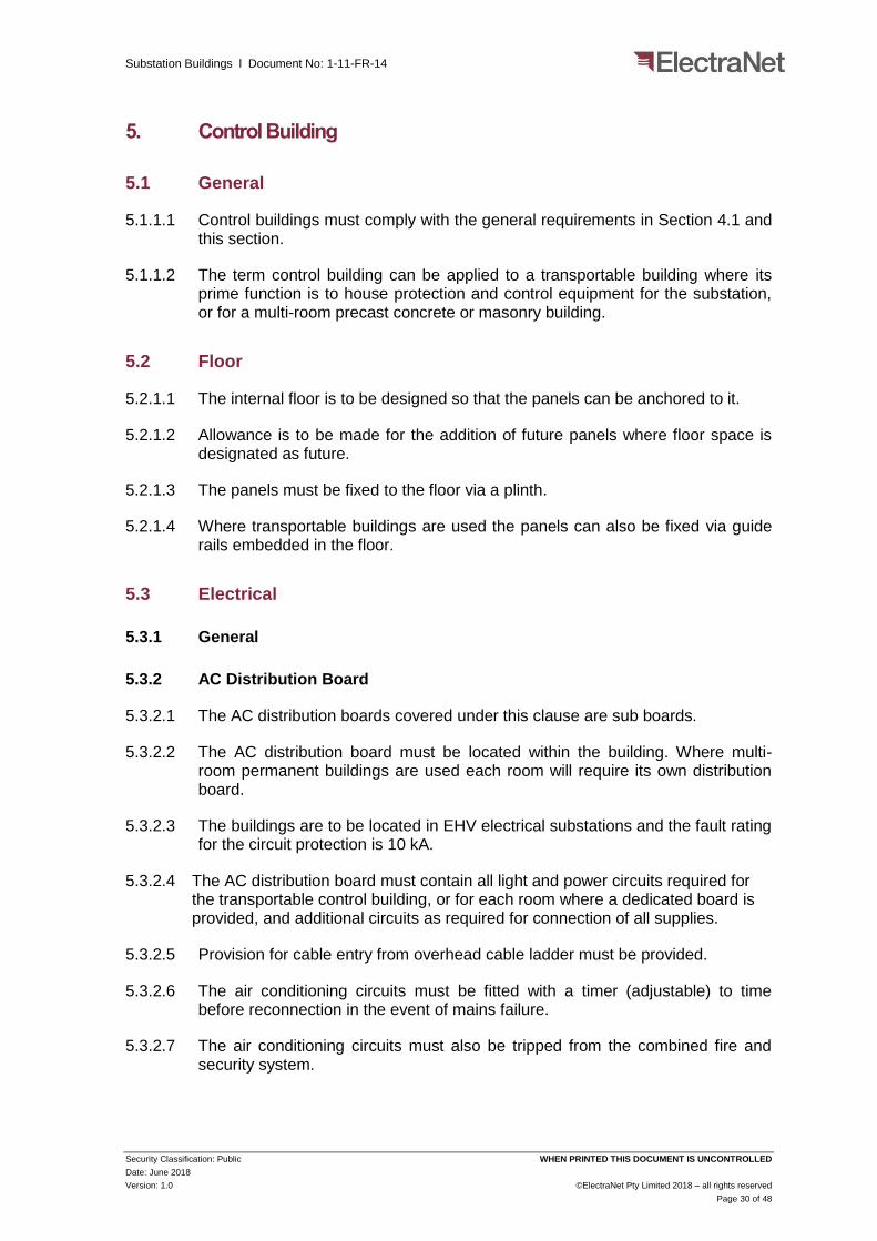
5.3.2 AC Distribution Board
5.3.2.1 The AC distribution boards covered under this clause are sub boards.
5.3.2.2 The AC distribution board must be located within the building. Where multi-room permanent buildings are used each room will require its own distribution board.
5.3.2.3 The buildings are to be located in EHV electrical substations and the fault rating for the circuit protection is 10 kA.
5.3.2.4 The AC distribution board must contain all light and power circuits required for the transportable control building, or for each room where a dedicated board is provided, and additional circuits as required for connection of all supplies.
5.3.2.5 Provision for cable entry from overhead cable ladder must be provided.
5.3.2.6 The air conditioning circuits must be fitted with a timer (adjustable) to time before reconnection in the event of mains failure.
5.3.2.7 The air conditioning circuits must also be tripped from the combined fire and security system.

Substation Buildings l Document No: 1-11-FR-14
Security Classification: Public WHEN PRINTED THIS DOCUMENT IS UNCONTROLLED
Date: June 2018
Version: 1.0 ©ElectraNet Pty Limited 2018 – all rights reserved
Page 31 of 48
5.3.2.8 The switchyard lighting circuits must be switched by a contactor, located in the main distribution board, and the on/off push buttons must be wired to a wall mounted junction box or on the main distribution board.
5.3.2.9 The AC distribution board must have sufficient spare fuse/circuit breaker space and capacity to add additional power circuits, if required, without modification.
5.3.3 DC Power for Control Buildings
5.3.3.1 Each control building must cater for the installation of at least two sets of battery banks, their associated chargers and the associated distribution systems.
5.3.3.2 Transportable control buildings will typically only be fitted with two sets of 110 V DC station battery and charger sets, which are normally designated as X and Y, in accordance with the requirements of document 1-09-FR-25 DC Supply Systems.
5.3.3.3 Typically transportable control buildings will not have 48 V DC telecommunications battery and charger sets installed unless a combined control and telecommunications building is specified for selected projects.
5.3.3.4 For precast concrete and reinforced masonry buildings where a dedicate battery room is required, the battery room will contain two sets of 110 V DC station battery and charger sets, which are normally designated as X and Y as well as two sets of telecommunications battery and charger sets which are designated as 1 & 2.
5.3.3.5 Where telecommunications battery banks and charger sets must meet the requirements of document 1-10-ADM-14 DC Power Supply Systems.
5.3.3.6 Station DC Power Supply battery bank terminals must be installed to face inwards to the building. X and Y DC banks are to be installed independent of one another to ensure complete segregation between X and Y is established.
5.3.3.7 Telecommunications DC Power Supply battery bank terminals must be installed to face inwards to the building. 1 and 2 DC banks are to be installed independent of one another to ensure complete segregation between 1 and 2 is established.
5.3.4 Earthing / Bonding
5.3.4.1 Two main earth points must be provided, one at either end of foundations containing rebar, or at either end of the base frame chassis for transportable buildings.
5.3.4.2 All external sheeting/cladding, all internal metalwork including the cable ladders, and the main panel earth ring cable must be bonded to earth potential.
5.3.4.3 The main panel earth ring cable must be a continuous copper conductor with green/yellow insulation of not less than 50 mm2 cross section and must be laid in the cable ladder to form a continuous ring above the panels.

Substation Buildings l Document No: 1-11-FR-14
Security Classification: Public WHEN PRINTED THIS DOCUMENT IS UNCONTROLLED
Date: June 2018
Version: 1.0 ©ElectraNet Pty Limited 2018 – all rights reserved
Page 32 of 48
5.4 Air Conditioning
5.4.1.1 The transportable control building, or control room in a multi-room building, must be fitted with two reverse cycle air conditioners capable of maintaining the room temperature at 23°C set up for cool-mode only.
5.4.1.2 Dry Bulb with the room equipment heat loading being that generated by ultimate equipment capacity of the building and a maximum external temperature of 40°C.
5.4.1.3 Each air conditioner must have the BTU (British Thermal Unit) capacity plus 30% to maintain the temperature of the entire building at 23°C in the event of failure of one of the units.
5.5 Fire Alarm Services
5.5.1 General
5.5.1.1 The substation fire alarm system, integrated within the substation security system, must consist of heat and early smoke detector systems located in multiple buildings/rooms on the site wired back to cubicles.
5.5.1.2 Shutdown of the air conditioning in the event of a fire in any of the buildings must be controlled from the fire alarm system.
5.5.1.3 The system requirements for the implementation of the fire alarms are provided in Template Drawings.
5.5.2 Design Drawings
5.5.2.1 All design drawings must be submitted to ElectraNet for comment.
5.5.2.2 The final as-built drawings and documentation must be supplied to ElectraNet no later than the delivery date for the equipment.
5.5.2.3 It is the Contractor's responsibility to ensure that the system and documentation complies with all standards and the minimum requirements of this specification.
5.5.3 Inspection of the Works (for Transportable Buildings)
5.5.3.1 The Contractor must ensure that during the period of manufacture such facilities as may be necessary to enable the inspection of the component parts of any item of the equipment and when requested, detailed working drawings of such components are available for inspection.
5.5.3.2 Notwithstanding the acceptance of its component parts any item of equipment which is subsequently found to have faulty workmanship or material must be liable to rejection by ElectraNet.
5.5.4 Detectors
5.5.4.1 All detectors, type and location requirements are detailed in the Standard and Template Drawings.

Substation Buildings l Document No: 1-11-FR-14
Security Classification: Public WHEN PRINTED THIS DOCUMENT IS UNCONTROLLED
Date: June 2018
Version: 1.0 ©ElectraNet Pty Limited 2018 – all rights reserved
Page 33 of 48
5.5.5 Access
5.5.5.1 Access for testing and maintenance must be provided to all detectors.
5.5.6 Alarm Bell
5.5.6.1 The alarm bell shall comply with AS 1603.6 “Automatic Fire Detection and Alarm Systems” Part 6 and with the requirements of document 1-11-FR-03 covering electronic security which also calls up the installation of external strobe lights fror each building.
5.5.7 Fire Indicator Panel (FIP)
5.5.7.1 A dedicated fire indication panel is not required.
5.5.7.2 Details of the combined fire and security system are provided in document 1-11-FR-03 Electronic Security.
5.5.8 DC Power supply
5.5.8.1 Supply and install an approved battery system in accordance with AS 4428.5.
5.5.8.2 Batteries that require the addition of electrolyte during service must not be accepted.
5.5.9 Connection to Substation Data System
5.5.9.1 The connection to the substation SCADA is detailed in document 1-11-FR-03 and the associated Template Drawings.
5.5.10 Location Diagram
5.5.10.1 This requirement is included in document 1-11-FR-03.
5.5.11 Radio Interference
5.5.11.1 The Fire Alarm System must be such that it does not cause any radio interference or interference of any other kind, to other services within the building and that the installation itself will not be affected by radio and TV transmissions.
5.5.12 Air Conditioning Shutdown
5.5.12.1 A clean set of change over contacts rated at a minimum of 230 V AC must be installed and wired to a suitably labelled terminal block within the FIP for each of the following functions:
a) One clean 230 V AC changeover contact to disconnect AC supply from the air conditioners via a contactor; and
b) One spare clean 230 V AC changeover contact.

Substation Buildings l Document No: 1-11-FR-14
Security Classification: Public WHEN PRINTED THIS DOCUMENT IS UNCONTROLLED
Date: June 2018
Version: 1.0 ©ElectraNet Pty Limited 2018 – all rights reserved
Page 34 of 48
5.5.13 Conduits and Wiring
5.5.13.1 All wiring must be carried out using two core red sheath TPS cable concealed throughout. Where cable is to be surface mounted prior approval in writing must be obtained from ElectraNet.
5.5.13.2 All surface wiring must be installed in rigid PVC conduit painted to match surrounding surfaces.
5.5.13.3 All conduits must be rigid PVC with a minimum diameter of 20 mm.
5.5.14 Maintenance Manuals
5.5.14.1 Maintenance manuals must be provided according to document 1-11-FR-03 requirements.
5.5.15 Spares
5.5.15.1 Spares must be provided according to document 1-11-FR-03 requirements.
5.5.16 Tests
5.5.16.1 Testing must be undertaken according to document 1-11-FR-03 requirements.
5.5.17 Tests and Service during the Defects Liability Period
5.5.17.1 Test and service during the Defect Liability Period must be according to the Contract requirements.
5.6 Diagram Board
5.6.1.1 The Contractor must provide and install a diagram board 1200 mm x 1200 mm and position it as shown on the typical drawing or as otherwise directed by ElectraNet.
5.6.1.2 Sheet the surface of the diagram board with bulletin tack board and white laminated plastic white board sheet in equal areas joining at the centre and fix a 32 mm x 20 mm x 2 mm clear anodised aluminium angle surround to all sides.
5.6.1.3 An aluminium tray to hold pens and eraser is to be fitted along the length of the bottom edge.
5.7 Furniture
5.7.1.1 Provide two desks of size 1500 mm long x 750 mm wide.
5.7.1.2 The height of the desktop is to be between 700 and 750 mm.
5.7.1.3 Frame to be 38 mm square metal tube with a 25 mm laminated desktop.
5.7.1.4 Desktop colour must be light grey or similar.
5.7.1.5 Desks must be free-standing and not fixed to the floor.

Substation Buildings l Document No: 1-11-FR-14
Security Classification: Public WHEN PRINTED THIS DOCUMENT IS UNCONTROLLED
Date: June 2018
Version: 1.0 ©ElectraNet Pty Limited 2018 – all rights reserved
Page 35 of 48
5.7.1.6 Provide two office chairs with:
a) Gas height adjustment;
b) Back height adjustment;
c) Swivel seat;
d) Medium size backrest; and
e) Material covered seat and back.
5.7.1.7 Provide a two-drawer filing cabinet for the housing of documents and drawings.
5.7.1.8 The furniture must be suitably packed and stored for transportation to avoid damage to other Equipment.

Substation Buildings l Document No: 1-11-FR-14
Security Classification: Public WHEN PRINTED THIS DOCUMENT IS UNCONTROLLED
Date: June 2018
Version: 1.0 ©ElectraNet Pty Limited 2018 – all rights reserved
Page 36 of 48
6. Amenities Building
6.1 General
6.1.1.1 The Amenities Building must comply with the general requirements for transportable buildings above and the following additional requirements of this Section.
6.1.1.2 Amenities can be supplied in a stand-alone transportable building, combined with the control transportable building or as part of a precast concrete or masonry building.
6.1.1.3 Irrespective of the application the requirements listed below must be followed except for items that are already provided when combined with a control building such as air conditioning, security systems, firefighting extinguishers or furniture.
6.2 Drainage
6.2.1 General
6.2.1.1 The drainage installation must be in accordance with the requirements of the Public and Environmental Health Act and the Local Authority and to the satisfaction of ElectraNet.
6.2.1.2 All work must be carried out by suitably qualified and licensed trades people.
6.2.1.3 The Contractor must record and document all dimensions on site and provide correct cover.
6.2.1.4 The Contractor must be responsible for the design, installation and testing of the sewerage or septic system, as required.
6.2.2 Drainage Layout Drawings
6.2.2.1 The Contractor must prepare drainage layout drawings to the requirements of the Local Authority. Make all applications and pay all fees required by the Local Authority to obtain approval for the drainage layout drawings.
6.2.2.2 The Contractor must prepare detailed layouts of the services and confirm locations and inverts of all services to and on the site before putting the work in hand and before any footing beams, etc., are formed.
6.2.2.3 No concrete must be placed prior to finalisation of drainage layouts in the area as no cutting will be permitted after construction.
6.2.2.4 The Contractor must make due and proper allowance for vertical drops and for all necessary diversions from lines shown as may be required to clear foundations and/or any other services and sub-surface work, and make allowance for all fittings occasioned thereby.

Substation Buildings l Document No: 1-11-FR-14
Security Classification: Public WHEN PRINTED THIS DOCUMENT IS UNCONTROLLED
Date: June 2018
Version: 1.0 ©ElectraNet Pty Limited 2018 – all rights reserved
Page 37 of 48
6.2.3 Septic System
6.2.3.1 Where specified, the Contractor must provide and install an approved brand all-purpose septic tank to Local Authority requirements with a minimum capacity of 1400 litres or as per the requirements of AS/NZS 1547 septic tank capacities, as appropriate.
6.2.3.2 The septic tank must be manufactured from high strength reinforced concrete with walls and base integrally cast. Other approved materials and preformed tanks must be acceptable. The tank must be complete with inlet and outlet junctions, inspection openings and covers.
6.2.3.3 The Contractor must arrange to carry out soil tests to determine the requirements for either absorption trenches or a transpiration area as may be required by the Local Authority. The construction of either the absorption trenches or the transpiration area must be to the requirements of the Local Authority.
6.2.3.4 Holding tanks are only to be used at locations close to rivers, at the specification of ElectraNet.
6.2.3.5 Any septic tank or holding tank used must be certified.
6.2.4 Testing
6.2.4.1 Testing of the drainage system must comply with all the requirements of the Public and Environmental Health Act and the Local Authority as required.
6.2.4.2 The Contractor must provide all labour and all materials and/or equipment necessary for carrying out of all tests and must make good any defective work and re-test as required.
6.2.4.3 On completion of all the drainage work provide a clearance certificate issued by the Local Authority as well as copies of all test certificates in duplicate to ElectraNet.
6.3 Plumbing
6.3.1 Regulations
6.3.1.1 The Contractor must provide the whole of the plumbing installation in accordance with the requirements of the Waste Control Regulations and the Local Authority as required, and to the satisfaction of ElectraNet.
6.3.1.2 In addition to plumbing work shown on the drawings and specified herein, all incidental plumbing work necessary for the proper completion of the work must be undertaken by the Contractor.
6.3.1.3 The Contractor must work throughout in accordance with the best trade practice by experienced and competent trade people under the supervision of a licensed plumber.

Substation Buildings l Document No: 1-11-FR-14
Security Classification: Public WHEN PRINTED THIS DOCUMENT IS UNCONTROLLED
Date: June 2018
Version: 1.0 ©ElectraNet Pty Limited 2018 – all rights reserved
Page 38 of 48
6.3.2 Access
6.3.2.1 The Contractor must ensure all services are free of each other and easily replaceable for their full length. Pipework with inspection openings, valves, etc. must be easily accessible.
6.3.3 Testing
6.3.3.1 The Contractor must provide all testing apparatus together with other incidental materials and labour that may be required to test the whole of the pipework by hydrostatic pressure or by any other methods as may be agreed with ElectraNet.
6.3.3.2 The Contractor must at the end of the test, provide the certificate of approval.
6.3.4 Drawings for Water Supply
6.3.4.1 The Specification Drawings must show diagrammatic layouts of the fixtures to receive water.
6.3.4.2 The Contractor must prepare in conjunction with other trades concerned, a more detailed layout of the services and discuss the work with ElectraNet before commencement.
6.3.4.3 It is important that the depth and location of all pipes, stacks, valves, fittings and cleaning eyes etc. be accurately plotted on a copy of the drawings and the Contractor must be held responsible for the accuracy of such "as built" information shown on the drawings. These "as built" drawings must be submitted to ElectraNet at the completion of each section of the work.
6.3.4.4 Where pipework extends through walls scheduled to have tile finish, the set out must be done in conjunction with the details showing centre lines of fixtures and outlets.
6.3.5 Workmanship
6.3.5.1 All piping in the building must be in copper and concealed wherever possible. All pipes used externally and/or underground must be High Density Polythene.
6.3.5.2 The Contractor must pressure-test all runs of piping for leaks before pipes are fully concealed.
6.3.5.3 All pipes, services, straps and fittings exposed to view internally must be Chromium plated.
6.3.5.4 Pipes must be held securely in place with approved holdfasts and straps, appropriate in type, size and finish to the pipe being fixed.
6.3.5.5 The Contractor must make joints to all copper pipes with either brazed or three piece union type fittings. Where pipes are brazed, protection must be used so that the surrounding materials must not be burnt or scorched.

Substation Buildings l Document No: 1-11-FR-14
Security Classification: Public WHEN PRINTED THIS DOCUMENT IS UNCONTROLLED
Date: June 2018
Version: 1.0 ©ElectraNet Pty Limited 2018 – all rights reserved
Page 39 of 48
6.3.5.6 The Contractor must connect to dissimilar materials through screwed brass fittings. Each item of plumbing brassware must consist throughout of the same alloy composition and must be of identical composition to any other brassware to which it is connected.
6.3.5.7 The Contractor must ensure all plumbing brassware, including unions, pipe fittings, taps and valves, is manufactured in accordance with AS 1565 and guaranteed to contain not less than 70/30 copper content with inclusion of not less than 0.02% and not more than 0.05% arsenic.
6.3.5.8 Note that the Contractor must be fully responsible for removal and replacement of brassware which corrodes or deteriorates through electrolytic action or dezincification, and for incidental damage and reinstatement.
6.3.5.9 The Contractor must undertake all work with licensed trade people in a first class manner and layout all pipe lines and other fittings in a neat and work like manner and true alignment and grade, to ElectraNet’s approval. Work must fit in with the general structure and architecture of the buildings and not conflict with that of other trades.
6.3.5.10 The Contractor must ensure piping through floors and walls is in sleeves and supported at every floor and, in the case of water piping, at an intermediate point also.
6.3.5.11 Water hammer must be avoided in all cases and obviate where occurring.
6.3.5.12 Hangers and other supports must be provided for pipelines in copper and space intervals to provide full support for lines.
6.3.5.13 The Contractor must conceal pipes in ducts, chases, above false ceilings or behind false work. Unconcealed piping around fittings must be chrome plated 18 gauge or brass with chrome plated fittings. Chrome plated pipes must be secured with approved C.P. pillar clips and C.P. fastenings. Wherever pipes pass through or enter walls, C.P. cast brass flanges must be provided of one piece construction secured to pipe. All work must be approved by ElectraNet.
6.3.6 Connection from Council Mains
6.3.6.1 The Contractor must arrange with the Local Council and pay all fees for a water connection to the building.
6.3.6.2 The Contractor must provide an isolation valve at the tank outlet and then a 25 mm diameter galvanized iron pipe fixed to the tank stand and extending from the bottom of the tank to the ground.
6.3.6.3 Provide and install a 25 mm diameter class 12 High Density Polythene pipe extending under the ground into the lunch room sink area within the building.
6.3.6.4 Extend the water supply with 13 mm take off branches to toilet, toilet tap, toilet basin and external tap on workshop. Pipes must not be run in any concrete work.

Substation Buildings l Document No: 1-11-FR-14
Security Classification: Public WHEN PRINTED THIS DOCUMENT IS UNCONTROLLED
Date: June 2018
Version: 1.0 ©ElectraNet Pty Limited 2018 – all rights reserved
Page 40 of 48
6.3.7 External Reticulation
6.3.7.1 The Contractor must extend the water supply with 13 mm take off branches to toilet, toilet tap, toilet basin and external tap on workshop. Pipes must not be run in any concrete work.
6.3.7.2 Ensure all materials and workmanship has ElectraNet’s approval.
6.3.7.3 Locate all piping, risers, stacks, vents, and branches inside the building and concealed in the ceiling, ducts, walls etc. Where piping is exposed under basins, and elsewhere, it must be chromium plated.
6.3.7.4 Fit all wastes to fittings with the correct chrome plated grate.
6.3.7.5 Fix all waste pipes with approved clips, straps, and holding devices, to maintain the correct falls. Ensure all pipes are easily accessible, especially inspection and cleaning eyes and openings.
6.3.8 Wastes
6.3.8.1 The Contractor must connect all fittings to the drainage system with waste pipes of the correct size, including for all traps, bends, inspection openings etc.
6.3.8.2 The Contractor must co-ordinate work with the drainer, and set out all fittings and floor wastes traps before commencing the installation.
6.3.8.3 Back vent fittings where required with the required size vent pipe must be provided by the Contractor. Vent pipes must be connected to the soil vent pipe below the roof. The number of vents taken through the roof must be minimised.
6.3.8.4 Fix expansion joints to all pipes wherever necessary.
6.3.8.5 Carry vent pipes through the roof, to the required height fit with a cowl, and secure with bracing all to the ElectraNet’s approval.
6.4 Electrical
6.4.1.1 Where a transportable amenities building is to be installed the Contractor must provide and install the main electrical switchboard (containing the AC changeover and main distribution functions for the substation) in the building and must make all connections for the correct functioning of all electrical items and equipment unless indicated otherwise by site specific documentation.
6.4.1.2 Where a permanent building is installed Contractor must provide and install the main electrical switchboard in the dedicated LV AC room.
6.5 Air Conditioning
6.5.1.1 Amenities and workshop areas must be air conditioned by one or more reverse cycle split-system or room air conditioners.
6.5.1.2 The air conditioning unit(s) must be capable of maintaining the room at 23 °C with an internal equipment heat loading of 4 kW and a maximum external ambient temperature of 40 °C.
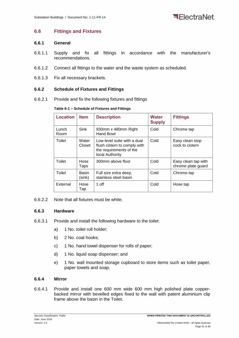
Substation Buildings l Document No: 1-11-FR-14
Security Classification: Public WHEN PRINTED THIS DOCUMENT IS UNCONTROLLED
Date: June 2018
Version: 1.0 ©ElectraNet Pty Limited 2018 – all rights reserved
Page 41 of 48
6.6 Fittings and Fixtures
6.6.1 General
6.6.1.1 Supply and fix all fittings in accordance with the manufacturer's recommendations.
6.6.1.2 Connect all fittings to the water and the waste system as scheduled.
6.6.1.3 Fix all necessary brackets.
6.6.2 Schedule of Fixtures and Fittings
6.6.2.1 Provide and fix the following fixtures and fittings
Table 6-1 – Schedule of Fixtures and Fittings
Location Item Description Water Supply
Fittings
Lunch Room
Sink 930mm x 480mm Right Hand Bowl
Cold Chrome tap
Toilet Water Closet
Low level suite with a dual flush cistern to comply with the requirements of the local Authority
Cold Easy clean stop cock to cistern
Toilet Hose Taps
300mm above floor Cold Easy clean tap with chrome plate guard
Toilet Basin (sink)
Full size extra deep, stainless steel basin
Cold Chrome tap
External Hose Tap
1 off Cold Hose tap
6.6.2.2 Note that all fixtures must be white.
6.6.3 Hardware
6.6.3.1 Provide and install the following hardware to the toilet:
a) 1 No. toilet roll holder;
b) 2 No. coat hooks;
c) 1 No. hand towel dispenser for rolls of paper;
d) 1 No. liquid soap dispenser; and
e) 1 No. wall mounted storage cupboard to store items such as toilet paper, paper towels and soap.
6.6.4 Mirror
6.6.4.1 Provide and install one 600 mm wide 600 mm high polished plate copper-backed mirror with bevelled edges fixed to the wall with patent aluminium clip frame above the basin in the Toilet.

Substation Buildings l Document No: 1-11-FR-14
Security Classification: Public WHEN PRINTED THIS DOCUMENT IS UNCONTROLLED
Date: June 2018
Version: 1.0 ©ElectraNet Pty Limited 2018 – all rights reserved
Page 42 of 48
6.6.5 Furniture
6.6.5.1 Provide one (1) desk of minimum size 1500 mm long x 750 mm wide and one desk (table) of minimum size 1800 mm long x 750 mm wide.
6.6.5.2 The height of the desktop must be between 700 and 750 mm. The frame must be 38 mm square metal tube or similar with a 25 mm thick laminated desktop.
6.6.5.3 Desktop colour must be light grey or similar. Desks must be free standing and not fixed to the floor.
6.6.5.4 Provide two (2) heavy duty office chairs with:
a) Gas height adjustment;
b) Back height adjustment;
c) Swivel seat;
d) Medium size backrest; and
e) Material covered seat and back.
6.6.5.5 Provide six heavy-duty desk chairs (without rollers).
6.6.5.6 Provide a two-drawer filing cabinets for the housing of documents and drawings.
6.6.5.7 The furniture must be suitably packed and stowed for transportation to avoid damage to other equipment.
6.6.6 Diagram Board
6.6.6.1 Provide and install a diagram board 1200 mm x 1200 mm and position it where directed by ElectraNet.
6.6.6.2 Ensure that the diagram board is constructed from 18 mm particle board. Sheet the surface of the diagram board with Pine Green bulletin tack board and white laminated plastic white board sheet in equal areas joining at the centre.
6.6.6.3 Ensure that the diagram board has a 32 mm x 20 mm x 2 mm clear anodised aluminium angle surround to all sides.
6.6.7 Substation Padlock and Key Boards
6.6.7.1 Substation Padlock and Key Boards are required at all ElectraNet sites for the location of isolator (and earth switch) specific padlocks and their associated keys. The padlock and key board is to contain sufficient hooks for all padlocks (and keys) for all installed plant associated with that building (e.g. 275 kV Control room or 132 kV control room).
6.6.7.2 The key board layout is to be based on the System Switching Diagram (SSD) for the site, and must be sufficiently spaced to allow each padlock to be located next to the item of plant on the diagram. Note at some substation sites the transformers are completely enclosed for noise limitation and firefighting purposes. The keys for accessing the enclosures and isolating the firefighting systems must also be located on the key board.

Substation Buildings l Document No: 1-11-FR-14
Security Classification: Public WHEN PRINTED THIS DOCUMENT IS UNCONTROLLED
Date: June 2018
Version: 1.0 ©ElectraNet Pty Limited 2018 – all rights reserved
Page 43 of 48
6.6.7.3 Board dimensions should be approximately 1400 mm x 1400 mm and must be black printing on a white background. The diagram and padlock spacing is to be sized based upon ultimate configuration of the substation, and have sufficient additional space for spare padlocks and keys. Hooks are to be large cup-hooks to accommodate keys, key tags and padlocks, and placed such that keys and associated tags provide minimal obstructions when reading the information on the board.
6.6.7.4 The following label must also be attached to the keyboard for identification:
Figure 6-1: Keyboard Label
6.7 Fire Alarm Services
6.7.1.1 The requirements for the amenities building are identical to those defined in Section 5.11 of this document where the fire alarming functions will be integrated into the substation security system.

Substation Buildings l Document No: 1-11-FR-14
Security Classification: Public WHEN PRINTED THIS DOCUMENT IS UNCONTROLLED
Date: June 2018
Version: 1.0 ©ElectraNet Pty Limited 2018 – all rights reserved
Page 44 of 48
7. Shed
7.1.1 General
7.1.1.1 The Contractor must provide a separate shed, where required and stated in the project specification. All greenfield substations must have a shed.
7.1.1.2 The shed must be nominally a 6 m x 4 m steel framed storage shed, with a single roller door and a separate personnel access door. The shed shall be supplied with a concrete floor and entry ramp, LED lighting and some single phase GPOs;
7.1.1.3 The shed must include at least one (non-rotary) roof vent.
7.1.1.4 Windows are not required.
7.1.2 Shed Electrical
7.1.2.1 A sub mains AC distribution board must be installed.
7.1.2.2 Air-Conditioning is not required.
7.1.3 Fire Services
7.1.3.1 Heat and Smoke Detectors are not required.
7.1.4 Extinguisher
7.1.4.1 Supply and install one 5.0 kg Carbon Dioxide (CO2) hand-held fire extinguisher with a sign to be located adjacent to the entry door.
7.1.5 Furniture
7.1.5.1 The Contractor must provide appropriate facilities to hang all of the portable earthing leads and to provide the required signage to display the site-specific fault ratings that the portable earth leads must comply with.

Substation Buildings l Document No: 1-11-FR-14
Security Classification: Public WHEN PRINTED THIS DOCUMENT IS UNCONTROLLED
Date: June 2018
Version: 1.0 ©ElectraNet Pty Limited 2018 – all rights reserved
Page 45 of 48
8. Brownfield Buildings
8.1 General
8.1.1.1 The following must apply for Brownfield applications, where the buildings were established prior to 2004.
8.2 Clearance and Equipment Spacing in Buildings
8.2.1.1 The Template Drawings apply to Greenfield applications.
8.2.1.2 There will be instances where work will need to be done to substations that were built prior to implementation of the present design standards and will typically apply to masonry buildings.
8.2.1.3 The table and figures below provide spacing requirements for use at these sites. These distances are for design guide purposes. Applications of these distances are shown in the following diagrams.
8.2.1.4 If during detailed design purposes it is found that these spacings cannot be met, then approval from ElectraNet will be required to use reduced spacings.
Table 8-1 – Clearances and equipment spacing in buildings
Equipment Clearance (mm)
Wall to front face of in line panels 1400
Wall to end face of in line panels / cubicles 1000
Wall to front face of tunnel board 1500
Between tunnel board front faces 1500
Wall to end of tunnel board (personal passage access) 1000
Wall to end of tunnel board (equipment passage access) 1500
Between cubicles front faces 1500
Wall to end face of indoor switchgear 1000
Wall to rear cubicles 1500
Pilot box to any earthed metal equipment / structure 1500

Substation Buildings l Document No: 1-11-FR-14
Security Classification: Public WHEN PRINTED THIS DOCUMENT IS UNCONTROLLED
Date: June 2018
Version: 1.0 ©ElectraNet Pty Limited 2018 – all rights reserved
Page 46 of 48
Figure 8-1 – Illustration of clearances from wall to panels

Substation Buildings l Document No: 1-11-FR-14
Security Classification: Public WHEN PRINTED THIS DOCUMENT IS UNCONTROLLED
Date: June 2018
Version: 1.0 ©ElectraNet Pty Limited 2018 – all rights reserved
Page 47 of 48
Figure 8-2 – Conventional building floorplan – illustration of clearances