Embed Size (px)
Citation preview
Geological Society of America Bulletin
doi: 10.1130/B30665.1 2013;125, no. 1-2;109-127Geological Society of America Bulletin
Lorna J. Strachan, Frank Rarity, Robert L. Gawthorpe, Paul Wilson, Ian Sharp and Dave Hodgetts Submarine slope processes in rift-margin basins, Miocene Suez Rift, Egypt
Email alerting servicesarticles cite this article
to receive free e-mail alerts when newwww.gsapubs.org/cgi/alertsclick
SubscribeAmerica Bulletin
to subscribe to Geological Society ofwww.gsapubs.org/subscriptions/click
Permission request to contact GSAhttp://www.geosociety.org/pubs/copyrt.htm#gsaclick
official positions of the Society.citizenship, gender, religion, or political viewpoint. Opinions presented in this publication do not reflectpresentation of diverse opinions and positions by scientists worldwide, regardless of their race, includes a reference to the article's full citation. GSA provides this and other forums for thethe abstracts only of their articles on their own or their organization's Web site providing the posting to further education and science. This file may not be posted to any Web site, but authors may postworks and to make unlimited copies of items in GSA's journals for noncommercial use in classrooms requests to GSA, to use a single figure, a single table, and/or a brief paragraph of text in subsequenttheir employment. Individual scientists are hereby granted permission, without fees or further Copyright not claimed on content prepared wholly by U.S. government employees within scope of
Notes
© 2013 Geological Society of America
on November 2, 2014gsabulletin.gsapubs.orgDownloaded from on November 2, 2014gsabulletin.gsapubs.orgDownloaded from
Submarine slope processes in rift-margin basins, Miocene Suez Rift, Egypt
Lorna J. Strachan1,2,†, Frank Rarity1, Robert L. Gawthorpe1,3, Paul Wilson1,4, Ian Sharp5, and Dave Hodgetts1
1School of Earth, Environment & Atmospheric Sciences, University of Manchester, Manchester, M13 9PL, UK2Geology, School of Environment, University of Auckland, Auckland 1142, New Zealand3Department of Earth Science, University of Bergen, N-5007 Bergen, Norway4Rock Deformation Research Ltd., Earth Sciences, University of Leeds, Leeds LS2 9JT, UK5Statoil, Sandsliveien 90, Bergen, Norway
ABSTRACT
New, high-resolution lithofacies data from hanging-wall Miocene synrift (Rudeis For-mation) exposures of the eastern Suez Rift margin, Egypt, reveal a submarine slope depo si tional system dominated by coarse-grained (pebble), heterogeneous, lenticu-lar beds, formed by coalescing turbidity currents, slumps, and debris fl ows deposited on deforming submarine substrate. Flows include prerift clasts and contemporaneous shallow-marine fossil fragments originating from an uplifted eastern hinterland. Multiple terrestrial drainages debouched onto faulted offshore slopes or fed small fan deltas on narrow shelves (<0.5 km width). Steep, sub-aerial rift-fl ank topog raphy also shed rock avalanche and landslide material offshore. The >360 m Rudeis Formation is divided into stratigraphic units R1 and R2, which exhibit upward-coarsening and unordered vertical motifs. Ongoing faulting infl uenced synrift deposition by controlling the locus of sub sidence and gravity base level. Meso-scale faults became inactive during Rudeis Formation times, with strain localized on the large rift border fault system, leading to a wider basin with time. We compare 16 sub-aqueous rift-margin basin fi lls from various tectonic and geographic settings and show they generally represent proximal gravity-flow deposits dominated by nongraded beds. We fi nd little commonality in vertical grain-size trends, highlighting the diversity of stratal architectures. Most basin fi lls show an inverse relationship between maximum clast size and shelf width. We propose a new model to capture the spectrum of sedimen-tary responses to rifting within rift-margin basins, varying as a function of shelf width, slope gradient, maximum grain size, and
textural maturity. Rudeis Formation strata at north Wadi Baba represent a particularly coarse-grained end member, deposited on steep slopes, with a narrow shelf.
INTRODUCTION
Rifting is a fundamental plate-tectonic process that shapes Earth’s surface and results in the rupture of continental crust and formation of sedimentary basins. Extension-induced land-scape evolution is controlled by faulting through footwall uplift and hanging-wall sub-sidence. Faulting therefore exerts a primary control on sedimentary processes and deposits by driving sedimentation, controlling fl uid-fl ow and gravity-fl ow pathways, and creating sites of deposition (Leeder and Gawthorpe, 1987; Gawthorpe and Leeder, 2000; Mack et al., 2009). Rift-bounding border faults are characterized by large throws, uplifted rift fl anks, and corresponding subsidence of rift valleys (Ebinger, 1989). Thus, rift-margin ba-sins, located immediately adjacent to border faults have the potential to form deep depo-centers characterized by complex high topo-graphic relief, multiple sediment sources, and a plethora of active sedimentary processes. Rift-margin basin synrift strata therefore may provide important sedimentary archives that are important hydrocarbon targets and that may provide insights into the sedimentological and structural evolution of divergent margins.
Several insightful studies of rift-margin basins from the United States, Greece, and Kenya fi lled with terrestrial and marginal marine strata have revealed reorganization of paleorivers around growing faults and folds, with related surface tilting driving channel avulsion, re-incision, and abandonment (e.g., Mack and Leeder, 1999; Saneyoshi et al., 2006; Backert et al., 2010). Resultant synrift rock types are complex, with coarse-grained assemblages forming coalescing deposits of alluvial fans, fl uvial channels, paleo-
sols, lacustrine beds, and fan deltas (e.g., Leeder et al., 1996).
The reconstruction of submarine slope and basin fl oor sedimentary processes in rift-margin basins has received less attention, with only a relatively small number of detailed studies (e.g., Surlyk, 1978, 1984; Ferentinos et al., 1988; Papatheodorou and Ferentinos, 1993; Leppard and Gawthorpe, 2006). This has resulted in a disconnect between the largely hypo thetical regional synrift tectono-stratigraphic models (Prosser, 1993; Bosence, 1998; Ravnås and Steel, 1998; Gawthorpe and Leeder, 2000) that predict upward-fi ning re-sulting from increased subsidence outpacing sedimentation, and detailed subregional-scale sedimentological studies that suggest much greater complexity of sedimentary processes, with gravity fl ows forming a prominent part of the basin fi ll (Surlyk, 1984; Ferentinos et al., 1988; Papatheodorou and Ferentinos, 1993; Leppard and Gawthorpe, 2006).
In this paper, we present results of a detailed (1 cm scale) lithofacies study of the El Qaa half graben (Moustafa, 1987, 1993; Sharp et al., 2000a, 2000b), an Oligocene–Miocene rift-margin basin on the eastern Suez Rift fl ank of the Sinai Peninsula, Egypt (Fig. 1). The purpose of our study was to use exception-ally well-exposed outcrops to quantify synrift slope and base-of-slope strata, allowing us to reconstruct paleofl ow processes and path-ways within a rift-margin basin. These data along with compiled published subaqueous rift-margin basin case studies are compared and allow us to speculate on general controls and predictable trends within analogous rift-border settings.
GEOLOGICAL SETTING
The Oligocene–Miocene intracontinental Suez Rift was a fault-bounded marine trough (Fig. 1). The eastern rift margin is divided into
For permission to copy, contact [email protected]© 2013 Geological Society of America
109
GSA Bulletin; January/February 2013; v. 125; no. 1/2; p. 109–127; doi: 10.1130/B30665.1; 13 fi gures; 1 table.
†E-mail: [email protected]
on November 2, 2014gsabulletin.gsapubs.orgDownloaded from

Strachan et al.
110 Geological Society of America Bulletin, January/February 2013
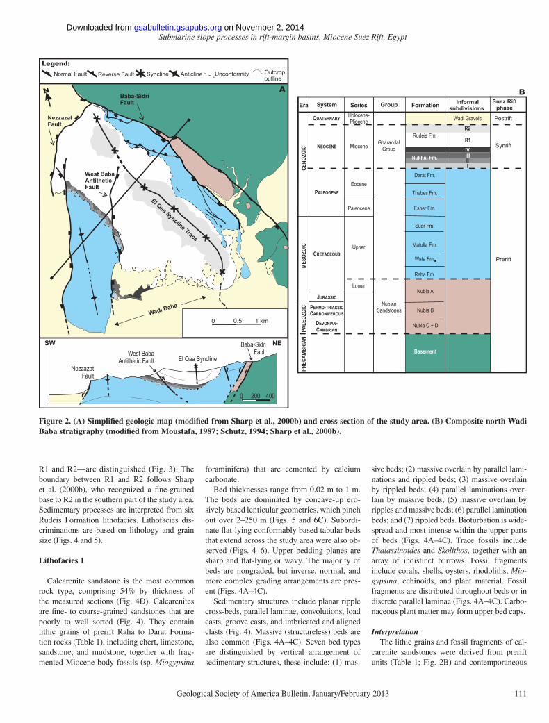
three distinct fault block provinces (Moustafa, 1993). The El Qaa fault and half graben form the central province, associated with steep, west-dipping faults (Moustafa, 1976). The El Qaa half graben is oriented NNW-SSE, and it is 12–20 km wide and 40 km long. It narrows to the north, where it terminates north of Wadi Baba, the location of this study (Moustafa, 1993; Gupta et al., 1999; Fig. 2).
Large-scale structures of north Wadi Baba from east to west include: (1) the rift-bound-ing, Baba-Sidri (normal) fault, with throws of 2–3.5 km down to the SW, which juxtaposes Precambrian–Cretaceous prerift units against Miocene synrift units; (2) the asymmetric El Qaa syncline, with a steep northeastern limb and gently inclined southwestern limb; (3) the West Baba antithetic (normal) fault, which is down-thrown to the E; and (4) the Nezzazat (normal) fault, throwing 3.5–5 km down to the WNW
(Moustafa, 1987, 1993; Gawthorpe et al., 1997; Sharp et al., 2000b; Khalil and McClay, 2001; Figs. 1 and 2A; Table 1).
Miocene synrift sedimentary rocks of the Gharandal Group unconformably overlie Cre-taceous to Paleogene prerift strata (Fig. 2; Table 1), and at north Wadi Baba, these rocks comprise the terrestrial, marginal marine, and marine Nukhul Formation, and the marine Rudeis Formation (Robson, 1971; Garfunkel and Bartov, 1977). Regional tectono-strati-graphic models, inclusive of Wadi Baba, en-visage a marine transgression during Nukhul to Rudeis Formation times linked to increas-ing fault displacement (Moustafa, 1987, 1993; Sharp et al., 2000a, 2000b). Sharp et al. (2000b) used 1–10-km-scale fi eld relationships (as re-vealed by mapping) to infer hemipelagic, tur-bidite and localized Gilbert delta deposition during Rudeis Formation times.
DATA AND METHODS
This study uses outcrop data to understand the sedimentary processes and depositional history of the Rudeis Formation in north Wadi Baba. Sedimentary logging (centimeter scale) and geologic mapping (1:10,000 scale) facili-tated interpretations of sedimentary processes and patterns, and structural fi eld relationships (Figs. 2 and 3).
RESULTS
Stratigraphy and Sedimentary Process
The Rudeis Formation is >360 m thick, bounded at its base by heavily bioturbated, con-densed, sheet Nukhul Formation beds (Malpas et al., 2005), and at its top by contemporary bad-land erosion. Two informal stratigraphic units—
33°10′
29°00′ 10 km
N
Baba-SidriFault
Study area
Nezzazat Fault
B
El QaaFault block
23.5 Ma
200 m
Med. Sea
Sinai
Studyarea
100 km
N
A
RedSea
Postrift
Synrift
Prerift
Normal Fault SynclineLegend: Anticline
Gulf ofSuez
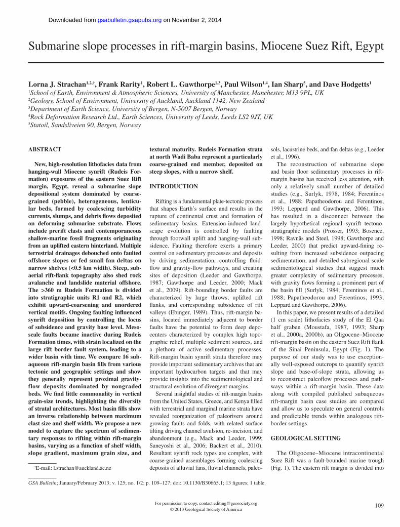
Figure 1. Geographic location and regional tectonic setting of the eastern Suez Rift border fault system. (A) Regional map showing study area location. (B) Simplifi ed geologic map and simplifi ed stratigraphic column of the El Qaa fault block modifi ed from Moustafa (1987, 1993); Sharp et al. (2000a, 2000b); and Khalil and McClay (2001).
TABLE 1. PRERIFT AND SYNRIFT ROCK TYPES FROM REGIONAL SUEZ RIFT STUDIES*
FormationThickness
ygolohtiL)m((arefinimarofgniniatnocenotsdnasdna,slram,selahscitsalC0022–003sieduR Globigerina sp. and Uvigerina sp.).
(suorefilissofylrooP.selahsdna,setaremolgnoc,senotsdnascitsalC001–05luhkuN Miogypsina sp. and Elphidium sp.)..enotsemilsuorefilissof,slramnworbdnaneerG89taraD
.setirdyhna,setimolod,sdnabdnaseludontrehctnadnuba,enotsemilcitilummuN008–041sebehT.slraM04–51rensE
.enotsemilhcir-cinagro,nworb-kraddnaklahcetihwevissaM022–001rduS.senotsdnasdna,sdnabtrehc,etimolod,klahc,senotsemil,)sretsyo(slramsuorefilissoF041allutaM
.slramdna,setimolod,senotsemil)setinomma(hcir-lissoforcaM051ataWsetinomma(suorefilissof,senotsdnascitinocualG08–02ahaR , echinoids, lamellibranchiata) limestones, red sandstones, and mudstone.
Nubian (Nubia A–D) 600–950 Marine and nonmarine (alluvial) red sandstones, red mudstones, conglomerates, shales, and limestones.Basement Unknown Feldspathic gneisses intruded by unmetamorphosed sills and dikes.
*Garfunkel and Bartov (1977); Sellwood and Netherwood (1984); Schutz (1994); El Azabi and El Araby (2007); Samuel et al. (2009).
on November 2, 2014gsabulletin.gsapubs.orgDownloaded from
Submarine slope processes in rift-margin basins, Miocene Suez Rift, Egypt
Geological Society of America Bulletin, January/February 2013 111
R1 and R2—are distinguished (Fig. 3). The boundary between R1 and R2 follows Sharp et al. (2000b), who recognized a fi ne-grained base to R2 in the southern part of the study area. Sedimentary processes are interpreted from six Rudeis Formation lithofacies. Lithofacies dis-criminations are based on lithology and grain size (Figs. 4 and 5).
Lithofacies 1
Calcarenite sandstone is the most common rock type, comprising 54% by thickness of the measured sections (Fig. 4D). Calcarenites are fi ne- to coarse-grained sandstones that are poorly to well sorted (Fig. 4). They contain lithic grains of prerift Raha to Darat Forma-tion rocks (Table 1), including chert, limestone, sandstone, and mudstone, together with frag-mented Miocene body fossils (sp. Miogypsina
foraminifera) that are cemented by calcium carbonate.
Bed thicknesses range from 0.02 m to 1 m. The beds are dominated by concave-up ero-sively based lenticular geometries, which pinch out over 2–250 m (Figs. 5 and 6C). Subordi-nate fl at-lying conformably based tabular beds that extend across the study area were also ob-served (Figs. 4–6). Upper bedding planes are sharp and fl at-lying or wavy. The majority of beds are nongraded, but inverse, normal, and more complex grading arrangements are pres-ent (Figs. 4A–4C).
Sedimentary structures include planar ripple cross-beds, parallel laminae, convolutions, load casts, groove casts, and imbricated and aligned clasts (Fig. 4). Massive (structureless) beds are also common (Figs. 4A–4C). Seven bed types are distinguished by vertical arrangement of sedimentary structures, these include: (1) mas-
sive beds; (2) massive overlain by parallel lami-nations and rippled beds; (3) massive overlain by rippled beds; (4) parallel laminations over-lain by massive beds; (5) massive overlain by ripples and massive beds; (6) parallel lamination beds; and (7) rippled beds. Bioturbation is wide-spread and most intense within the upper parts of beds (Figs. 4A–4C). Trace fossils include Thalassinoides and Skolithos, together with an array of indistinct burrows. Fossil fragments include corals, shells, oysters, rhodoliths, Mio-gypsina, echinoids, and plant material. Fossil fragments are distributed throughout beds or in discrete parallel laminae (Figs. 4A–4C). Carbo-naceous plant matter may form upper bed caps.
InterpretationThe lithic grains and fossil fragments of cal-
carenite sandstones were derived from prerift units (Table 1; Fig. 2B) and contemporaneous
System Group FormationEra Informalsubdivisions
Wadi GravelsQUATERNARY
Series
Holocene-Pliocene Postrift
Suez Riftphase
M ESO
ZOIC
CENO
ZOIC
PERMO-TRIASSICCARBONIFEROUS
DEVONIAN-CAMBRIAN
GharandalGroup
NubianSandstones
R1
R2
IIIIIIIV
Rudeis Fm.
Nukhul Fm.
Darat Fm.
Thebes Fm.
Esner Fm.
Sudr Fm.
Matulla Fm.
Wata Fm.
Raha Fm.
Nubia A
Nubia B
Nubia C + D
Basement
NEOGENE
PALEOGENE
CRETACEOUS
Miocene
Eocene
Paleocene
Upper
Lower
JURASSICPA
LEOZ
OIC
PREC
AMBR
IAN
Synrift
Prerift
B
Wadi Baba
NezzazatFault
NBaba-SidriFault
West BabaAntitheticFault
El Qaa Syncline Trace
A
Normal Fault Reverse Fault Syncline
Legend:Unconformity Outcrop
outlineAnticline
0 200 400
NezzazatFault
West BabaAntithetic Fault El Qaa Syncline
Baba-SidriFault
SW NE
0 mk15.0
.
Figure 2. (A) Simplifi ed geologic map (modifi ed from Sharp et al., 2000b) and cross section of the study area. (B) Composite north Wadi Baba stratigraphy (modifi ed from Moustafa, 1987; Schutz, 1994; Sharp et al., 2000b).
on November 2, 2014gsabulletin.gsapubs.orgDownloaded from

Strachan et al.
112 Geological Society of America Bulletin, January/February 2013
Miocene reefs. The range of sorting implies variable textural maturities, with both imma-ture and mature grain populations. Such mixed populations suggest that sediment particles under went varied amounts of reworking, sort-ing, and transport prior to being redeposited by sub marine unidirectional fl ows.
Abundant erosionally based, lenticular beds suggest that unidirectional fl ows were highly erosive and able to scour the substrate. Sev-eral processes result in scoured seafl oor de-pressions, including: (1) allogenic megafl ute and fl ute formation (e.g., Elliott, 2000; Kane et al., 2009), (2) slump scar formation (Locat
and Lee, 2002), and (3) erosional turbidite channel formation (e.g., Kneller, 2003; Pyles et al., 2010). Lenticular beds <10 m across were formed by localized scouring, perhaps linked to megafl ute formation. Formation by erosional, channelized turbidity currents is favored here for wider lenticular beds (up to
Z FS MSCS G P C Bo Bl
340
360
60
80
100
120
140
160
180
200
220
240
260
280
300
320
20
40
Heigh
t in se
ction
(m)
Heigh
t in se
ction
(m)
20
40
60
80
100
120
140
160
180
200
220
240
260
280
300
320
R2
R1
Grain sizeZ FS MS CS G P C Bo Bl
R2
Composite log of Southern end of outcrop
R1
Grain size
Composite log of Northern end of outcrop 0 0.5 1 km
Log8
Log6
Log 10
Log 12
Log 9
Log 11
Log7
Log 5Log 4
Log 3
Log 1
Log 2
N
Log 2
Log 12
Rudeis Fmn
Nukhul Fmn
R1
R2
IIIIIIIV
Z FS MSCS G P C Bo BlGrain size
Silt
Fine s
and
Mediu
m sa
ndCo
arse
sand
Gran
ulePe
bble
Cobb
leBo
ulder
Bloc
k
20
Heigh
t in S
ectio
n (m) A
n=13
Flutes & cross-beds
n=3
Grooves
Grooves
n=20n=36
Flutes & cross-beds
0
5
10
15
20
25
30
Perce
ntage
of m
udsto
ne
withi
n log
NE SWNE-SW transect of 12 logs
not to scale
n= 2560
13
4
5
6
7 8
9
10
1112
B
05101520
25
Aver
age g
rain
size (
mm)
3
1
4 6 9
11
Percentage mudstone Average grain size
5
2 12
Figure 3. (A) Composite sedimentary logs from northern (logs 1 and 5) and southern (logs 2, 11, and 12) ends of the outcrop. Informal stratigraphic units R1 and R2 are highlighted. Simplifi ed geological map shows log locations. Summary rose diagrams show paleocurrents from stratigraphic units R1 and R2. (B) Average (mean) grain size and mudstone content statistics from each log. Numbers correspond to logs.
on November 2, 2014gsabulletin.gsapubs.orgDownloaded from
Submarine slope processes in rift-margin basins, Miocene Suez Rift, Egypt
Geological Society of America Bulletin, January/February 2013 113
250 m wide) because: (1) scours are infi lled by sandstones, suggesting minimal time be-tween channel erosion and aggradation; (2) the lenticular geometry of the beds rep-resents typical channel-form cross-sectional shapes (e.g., Pyles et al., 2010) and implies full containment of fl ows; (3) depositional sedimentary structures onlap basal surfaces, indicating infi lling of topography via aggra-dation rather than draping of preexisting re-lief; (4) the lateral scale of the scouring, up to 250 m, is wider than other outcrop examples of megafl utes (1–45 m; Elliott, 2000; Kane et al., 2009); and (5) there is little evidence of slumps or slides infi lling scours, as would be expected if they were mass movement scars. Flat-lying conformably based tabular beds are interpreted as deposits from extensive uncon-fi ned, depositional turbidity currents that were able to deposit across the studied area.
The dominance of nongraded, massive beds implies rapid aggradation that suppressed trac-
tional transport, steady fl ows, or postdepo-sitional obscuration by erosion, liquefaction, or bioturbation (Baas, 2004). Bioturbation-induced masking of grading and sedimentary structures is mainly confined to the upper parts of beds, suggesting massive beds likely resulted from active fl ow processes. Less com-mon graded beds and unidirectional bed forms preserve seven proximal turbidite beds types, including: Ta, Tabc, Tac, Tba, Taca, Tb, and Tc (Bouma, 1962), which resulted from waning, waxing, and more temporally complex fl ows (Kneller, 1995).
Fragmented Miocene marine fossils preserve evidence of erosive fl ows that swept through reefs. The locus of deposition, however, is deemed to have been further offshore in water depths below storm-wave base, because evi-dence of wave or storm reworking is absent. Trace fossils are marine but water depth invari-ant, and do not provide any information about paleo–water depths.
Lithofacies 2
Pebbly sandstones constitute 5% of the mea-sured section by thickness (Fig. 4D). They include fi ne- to very coarse-grained sandstones that contain more than 20% granule to large peb-bles (Figs. 4A–4C). Pebbly sandstones are mod-erately to poorly sorted and contain a variety of prerift lithic clasts, including well-rounded polished cherts, subrounded sandstones, and subangular limestones (Table 1). Beds are 0.2–0.6 m thick and can be tabular with conformable and fl at-lying bases, or lenticular, pinching out over tens to 100 m with concave-up bases (Figs. 4A–4C and 5D–5F). Upper bedding planes are sharp and fl at-lying (Figs. 4A–4C). Beds are dominantly nongraded, but normal, inverse, and more complex vertical grading patterns are also observed (Figs. 4A–4C and 5D–5F).
Pebbly sandstone bed bases may exhibit load casts and grooves, but above basal bedding planes are typically massive, with clasts distributed
Key
Sedimentary structures
Lithology
Sandstone
MudstoneClast-supported conglomerateMatrix-supported conglomerateChert clast
Sandstone clast
Limestone clast
Ripple cross-beds
Parallel laminae
Bedding
Contortion
Load cast
Groove cast
Chert fragments
Infilled burrow
Burrows
Carbonaceous material
Shell material
Coral
Branching bryozoan
Gastropod
249
250
251
252
254
255
258
253
256
257
245
247
246
248
119
114
115
116
117
118
106
108
107
109
110
111
112
113
14
9
10
11
12
13
1
3
2
4
5
Hei
ght i
n se
ctio
n (m
)
Hei
ght i
n se
ctio
n (m
)
Hei
ght i
n se
ctio
n (m
)
6
7
8
Log 10 Log 12Log 3
A B C D
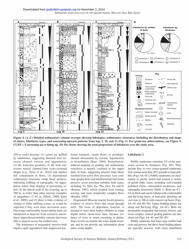
Lithofacies by number of beds
Lithofacies by thickness
n= 1374 n= 1772
Lithofacies 1
Lithofacies 2
Lithofacies 3
Lithofacies 4
Lithofacies 5
Lithofacies 6
vf vc G P CU/FULith. Mst Sst CongC B1 23 45 6
Lithofacies
vf vc G P CU/FULith. Mst Sst CongC B1 23 45 6
Lithofacies
vf vc G P CU/FULith. Mst Sst CongC B1 23 45 6
Lithofacies
Figure 4. (A–C) Detailed sedimentary column excerpts showing lithologies, sedimentary structures (including the distribution and shape of clasts), lithofacies types, and coarsening-upward patterns from logs 3, 10, and 12 (Fig. 3). For grain-size abbreviations, see Figure 3. CU/FU—Coarsening up or fi ning up. (D) Pie charts showing the total proportions of lithofacies over the study area.
on November 2, 2014gsabulletin.gsapubs.orgDownloaded from
Strachan et al.
114 Geological Society of America Bulletin, January/February 2013
throughout the bed. Crude clast-rich parallel lami-nae and bands are infrequently observed in the upper and middle parts of beds (Figs. 4A–4C and 5E). Bioturbation is uncommon. Pebbly sand-stone beds include fragmented corals and shells, including oysters.
InterpretationPebbly sandstones are the product of sub-
marine unidirectional fl ows that redeposited coarse-grained bimodal sediment. The high clast content of beds suggests that fl ows were rapidly moving, high-energy events. The vari-ety of sorting and clast shapes suggests deposi-tion from both texturally mature and immature fl ows. Such variation can be explained by variability of sediment source areas, or linked to submarine unidirectional flow processes whereby longer-duration flow deposits are better sorted.
Tabular, fl at-based beds result from uncon-fi ned, depositional fl ows. Lenticular erosive beds result from initially erosive and then depositional fl ows that deposited their loads within incised channels. Nongraded massive beds (Ta or S3
beds; Bouma, 1962; Lowe, 1982) dominate the preserved record and imply deposition from steady turbidity currents with high aggradation rates that suppressed the formation of tractional bed forms. Atypical normally graded beds with parallel laminae (Tab; Bouma, 1962) imply in-frequent waning fl ows. Uncommon inversely graded (Tba or S3-2 beds; Bouma, 1962; Lowe, 1982) and more complex vertically graded beds (S3-R2-S3 beds; Lowe, 1982) additionally sug-gest waning and temporally more complex fl ow behaviors. The inclusion of fragmented shallow-water fauna implies initiation of fl ows in shallow water, but the absence of shallow-water sedimen-tary structures and bioturbation implies deposi-tion further offshore below storm-wave base.
Lithofacies 3
Mudstones form 16% of the succession by thickness. Grain sizes range from clay to silt with fi ne to medium sand-sized shell fragments. Bed and laminae thicknesses are between 5 mm and 2 cm (Figs. 4A–4C). Mudstone beds are commonly stacked on top of each other and can
reach cumulative thicknesses of >6 m (Figs. 5G–5I). Beds and laminae appear tabular; how-ever, they are frequently truncated by erosive overlying sandstones and conglomerates (litho-facies 1–2, 4–6) that prevent lateral correlation of mudstones. Mudstones are occasionally de-formed by folding and faulting (Fig. 5I). Bed and lamination boundaries are sharp or grada-tional, and generally conformable and fl at lying (Figs. 4A–4C). Beds are typically nongraded, but inverse and more complex vertical grading is observed. Parallel laminae, siltstone lenses, and massive beds were observed (Figs. 4A–4C).
Satin spar fi brous gypsum bands are com-monly interbedded with mudstones and can form undeformed laminae and beds, folded in-tervals, and anastamosing branching networks that crosscut bedding (Figs. 5G–5I). Bioturba-tion was rarely observed, but where present, Chondrites traces were identifi ed.
InterpretationMudstone deposition is indicative of low-
energy deposition devoid of coarse-grained input. Thin beds and laminae suggest slow or
LIT
HO
FAC
IES
1LI
TH
OFA
CIE
S 2
LIT
HO
FAC
IES
3
CA
LCA
RE
NIT
EP
EB
BLY
SA
ND
STO
NE
MU
DS
TON
E
4 m
BeddedCalcarenite Sandstones
Parallel laminae
BeddedCalcarenite Sandstones 0.5 m
0.08 m
0.3m
0.01 m
Pebbly sandstonebeds
Graded pebbly sandstones
0.08 m
Interbedded mudstones and calcarenites
Anastamosing Gypsum0.3 m
Folded interval
Interbedded mudstones and calcarenites
2 m
Mudstone intervals
A B C
D F
G H
E
IGypsum
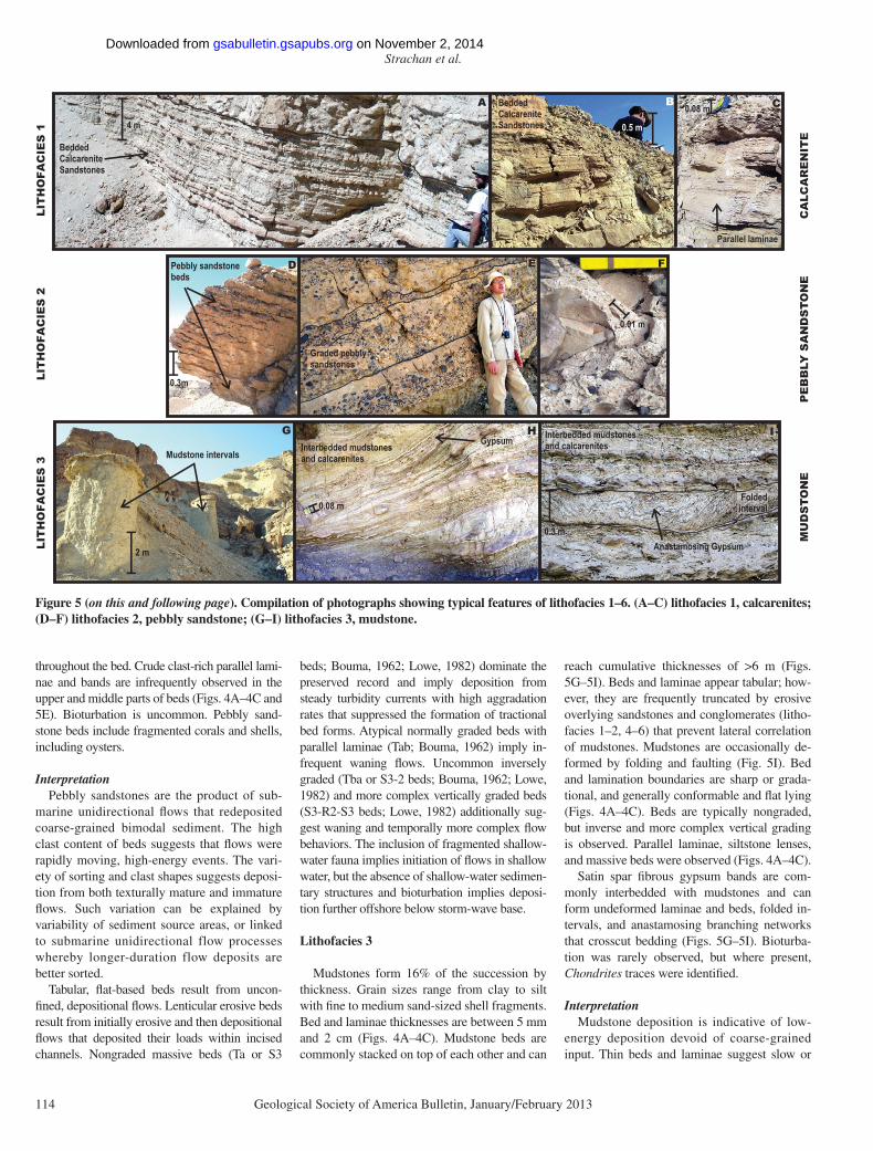
Figure 5 (on this and following page). Compilation of photographs showing typical features of lithofacies 1–6. (A–C) lithofacies 1, calcarenites; (D–F) lithofacies 2, pebbly sandstone; (G–I) lithofacies 3, mudstone.
on November 2, 2014gsabulletin.gsapubs.orgDownloaded from

Submarine slope processes in rift-margin basins, Miocene Suez Rift, Egypt
Geological Society of America Bulletin, January/February 2013 115
dilute deposition, and cumulative mudstone thicknesses of >6 m suggest extended periods of hemipelagic settling or localized ponding of muddy gravity fl ows. The lack of lateral bed continuity implies either erosion by later grav-ity fl ows or that deposition was localized. Some mud deposition was associated with slopes that later slumped. Nongraded, laminated beds resulted from hemipelagic deposition, while inversely graded beds suggest deposition from unidirectional mud-rich turbidity currents. The association between gypsum and mudstones resulted from diagenetic gypsum formation that displaced host mudstones. The scarcity of trace fossils suggests that conditions were generally unfavorable for burrowing organisms. However, at times, Chondrites ichnofauna suggests low-oxygen conditions.
Lithofacies 4
Chert-dominated oligomict conglomerates are the most common conglomerate type en-countered, forming 12% of the succession by thickness (Fig. 4D). They include well-sorted,
well-rounded, pebble- to boulder-sized prerift (Thebes Formation) chert clasts and subordinate poorly sorted, angular prerift limestone clasts and marine Miocene fossil fragments. Con-glomerates can be matrix-supported, clast-sup-ported, or range from clast- to matrix-supported conglomerates up bed (Figs. 4A–4C, 5J–5L, 6B, and 6C). Matrix ranges from mudstone to very coarse sandstone.
Beds are 5 cm to 15 m thick and often len-ticular, pinching out over 10–2000 m (Figs. 4, 6B, and 6C). Minor tabular or folded beds are present. Bed bases are gently curved and trun-cate underlying strata. Upper bedding planes are fl at lying (Figs. 4A–4C and 5J–5L). Nongraded, massive beds are common; infrequent normal, reverse, and more complex vertical grading is also observed (Figs. 4A–4C). Chert-dominated conglomerates can display inclined clast im-brication, locally developed fl at-lying bedding, steeply dipping bedding planes, and amalga-mation surfaces (Figs. 4A–4C, 5J–5L, 6B, and 6C). Highly irregular lenses (10 m wide, up to 3 m high) of conglomerate, containing inclined beds, are also observed on laterally extensive
thin beds (Figs. 6B and 6C). Fragmented fossils, including corals and oyster shells, are observed.
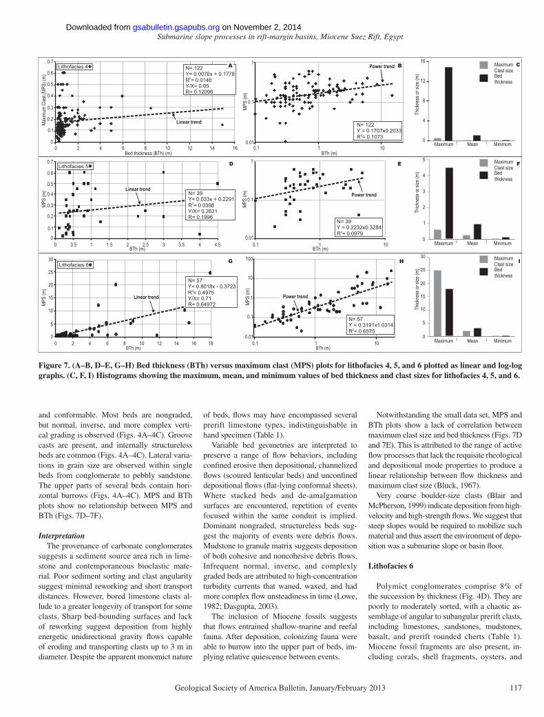
Maximum clast size (MPS) and bed thickness (BTh) plots (after Bluck, 1967) reveal that there is no relationship between MPS and BTh and that thicker beds have a smaller range of maxi-mum clast sizes (Figs. 7A–7C).
InterpretationWell-sorted texturally mature chert clasts
dominate lithofacies 4 and suggest that sediment source areas were rich in well-sorted cherts, and that texturally immature limestone and contem-poraneous Miocene fossils were entrained into fl ows during redeposition. Erosively based, im-bricated, massive, clast- and matrix-supported conglomerates are interpreted as the deposits of unidirectional submarine fl ows. The lenticular nature of most beds suggests that fl ows were confi ned within scoured surfaces. The large range in scour widths from 10 to 2000 m im-plies a range of scales of erosion. We suggest that some surfaces were scoured by erosive pre-cursor fl ows that bypassed to deposit material further downstream, while other fl ows scoured
LIT
HO
FAC
IES
4LI
TH
OFA
CIE
S 5
LIT
HO
F AC
IES
6
CH
ER
T-D
OM
INA
TE
DO
LIG
OM
ICT
CO
NG
LOM
ER
AT
ELI
ME
STO
NE
MO
NO
MIC
T
CO
NG
L OM
ER
AT
EP
OLY
MIC
T
CO
NG
L OM
ER
AT
E
0.3 m
Laterally extensive unit
Amalgamated & crosscutting beds
0.3 m
0.1 m
15 m
Lenticular conglomerate beds
0.4 mClast-supported
Matrix-supported
5 mFolded interval
Load and flamestructures
20 m
Laterally extensive,poorly sorted bed
J K L
M
P Q R
N O
Chert conglomerate
Sandstone boulders
Limestone clasts
Matrix-supported
Figure 5 (continued ). (J–L) lithofacies 4, chert-dominated oligomict conglomerate; (M–O) lithofacies 5, limestone monomict conglomerate; and (P–R) lithofacies 6, polymict conglomerate.
on November 2, 2014gsabulletin.gsapubs.orgDownloaded from

Strachan et al.
116 Geological Society of America Bulletin, January/February 2013
their own bases and were also contained within them. Bedding and amalgamation surfaces also imply localized erosion of channelized fl ows. Several localized sediment accumulations of inclined anomalously thick beds (Figs. 6B and 6C) are tentatively interpreted as turbidite chan-nel bars or lateral accretion packages (Abreu et al., 2003; Hesse et al., 2001). Such structures,
along with amalgamation surfaces, imply pro-tracted periods of channelized fl ow, where sedi-ment bypass, deposition, and migration from multiple gravity fl ows resulted in preserved composite deposits. The scarcity of tabular beds suggests that unconfi ned fl ows were atypical. Rare folded conglomerate beds are interpreted as submarine slumps.
The variety of graded beds and matrix types suggests that several fl ow rheologies and mech-anisms deposited chert-rich conglomerates, in-cluding: (1) cohesive and noncohesive debris fl ows that deposited nongraded matrix- and clast-supported beds with mudstone and sand-stone matrices; (2) waning high-concentration turbidity currents that deposited normally graded matrix-supported beds (R3S3 beds; Lowe, 1982); (3) waxing high-concentration turbidity currents that deposited inversely graded matrix-supported beds (S3R3 beds; Lowe, 1982); and (4) fl ows transitioning from debris fl ows to tur-bidity currents with time (R3S3 overlain by Tb; Bouma, 1962; Lowe, 1982).
Maximum clast size (MPS) and bed thickness (BTh) plots have been used to demonstrate the link between fl ow thickness and competence, which, in cohesive debrites, results in linear trends between MPS and BTh (Bluck, 1967; Nemec and Steel, 1984). Here, there is no rela-tionship between MPS and BTh (Figs. 7A and 7B). We suggest that the absence of any rela-tionship results from: (1) the range of gravity-fl ow processes and deposition modes; (2) the narrow range of clast sizes available to fl ows (i.e., presorting); and (3) the presence of amal-gamated beds.
The chert-dominated conglomerates do not preserve evidence of shallow-water or storm-wave reworking. This, together with implied gravity-fl ows processes, suggests deposition on a submarine slope or base of slope. Fossil frag-ments, however, imply that fl ows initiated in shallower waters, where they eroded shallow-water detritus, sweeping it downslope in ener-getic redeposition events.
Lithofacies 5
Carbonate oligomict conglomerates are rare, comprising 5% of the succession by thickness. They are composed of pebble- to boulder-sized prerift limestone clasts (Table 1; Figs. 4A–5C and 5M–5O) that are poorly to moderately sorted, occasionally bored, and angular to sub-angular, together with fragmented and intact Miocene shells, corals, and rhodoliths. Carbon-ate conglomerates can be matrix-supported, clast-supported, or both matrix- and clast-supported conglomerates within the same bed (Figs. 5N and 5O). Variable matrix types range from mudstones to granule.
Beds are 10 cm to 4.5 m thick. Bed geom-etries include 100–1000-m-wide lenticular beds, tabular sheets, and laterally de-amalga-mated beds (Figs. 4A–4C and 5M). Bed bases are sharp, and can be conformable and fl at ly-ing, or truncating and concave up (Figs. 4A–4C, 5M, and 5N). Upper bed contacts are fl at lying
Baba-Sidri Fault
NW SE
Lithofacies 4
BeddedLithofacies 1
Local lenticularity
Log 2
Lenticular beds
30 m
Incisional horizon
Laterally extensive lithofacies 6
Log 10
C
Log 8
4 m
W Log 9
Extreme lenticularity
Inclined bedding
West Baba Antithetic Fault
Lithofacies 1Lithofacies 4
B
E
W E
2 m
Lithofacies 1
Large angular to subangular clasts
Lithofacies 6
Truncation and incision
A
Sketch Log
Figure 6. (A) Truncation and incision of calcarenites (lithofacies 1) by chaotic, lenticular poly-mict conglomerates (lithofacies 6). (B) Extreme lenticularity of chert-dominated oligomict conglomerate (lithofacies 4) associated with the West Baba antithetic fault. (C) Overview showing bed geometries of calcarenites, chert, and polymict conglomerates. Conglomerates are highly erosive and exhibit irregular bed thicknesses. Calcarenites are lenticular and erosive. Local development of a chert conglomerate with inclined bedding is interpreted as a within-channel lateral accretion package.
on November 2, 2014gsabulletin.gsapubs.orgDownloaded from
Submarine slope processes in rift-margin basins, Miocene Suez Rift, Egypt
Geological Society of America Bulletin, January/February 2013 117
and conformable. Most beds are nongraded, but normal, inverse, and more complex verti-cal grading is observed (Figs. 4A–4C). Groove casts are present, and internally structureless beds are common (Figs. 4A–4C). Lateral varia-tions in grain size are observed within single beds from conglomerate to pebbly sandstone. The upper parts of several beds contain hori-zontal burrows (Figs. 4A–4C). MPS and BTh plots show no relationship between MPS and BTh (Figs. 7D–7F).
InterpretationThe provenance of carbonate conglomerates
suggests a sediment source area rich in lime-stone and contemporaneous bioclastic mate-rial. Poor sediment sorting and clast angularity suggest minimal reworking and short transport distances. However, bored limestone clasts al-lude to a greater longevity of transport for some clasts. Sharp bed-bounding surfaces and lack of reworking suggest deposition from highly energetic unidirectional gravity fl ows capable of eroding and transporting clasts up to 3 m in diameter. Despite the apparent monomict nature
of beds, fl ows may have encompassed several prerift limestone types, indistinguishable in hand specimen (Table 1).
Variable bed geometries are interpreted to preserve a range of fl ow behaviors, including confi ned erosive then depositional, channelized fl ows (scoured lenticular beds) and unconfi ned depositional fl ows (fl at-lying conformal sheets). Where stacked beds and de-amalgamation surfaces are encountered, repetition of events focused within the same conduit is implied. Dominant nongraded, structureless beds sug-gest the majority of events were debris fl ows. Mudstone to granule matrix suggests deposition of both cohesive and noncohesive debris fl ows. Infrequent normal, inverse, and complexly graded beds are attributed to high-concentration turbidity currents that waned, waxed, and had more complex fl ow unsteadiness in time (Lowe, 1982; Dasgupta, 2003).
The inclusion of Miocene fossils suggests that fl ows entrained shallow-marine and reefal fauna. After deposition, colonizing fauna were able to burrow into the upper part of beds, im-plying relative quiescence between events.
Notwithstanding the small data set, MPS and BTh plots show a lack of correlation between maximum clast size and bed thickness (Figs. 7D and 7E). This is attributed to the range of active fl ow processes that lack the requisite rheological and depositional mode properties to produce a linear relationship between fl ow thickness and maximum clast size (Bluck, 1967).
Very coarse boulder-size clasts (Blair and McPherson, 1999) indicate deposition from high-velocity and high-strength fl ows. We suggest that steep slopes would be required to mobilize such material and thus assert the environment of depo-sition was a submarine slope or basin fl oor.
Lithofacies 6
Polymict conglomerates comprise 8% of the succession by thickness (Fig. 4D). They are poorly to moderately sorted, with a chaotic as-semblage of angular to subangular prerift clasts, including limestones, sandstones, mudstones, basalt, and prerift rounded cherts (Table 1). Miocene fossil fragments are also present, in-cluding corals, shell fragments, oysters, and
Bed thickness (BTh) (m)
Maxim
um C
last (
MPS)
(m)
0.1
0.2
0.3
0.4
0.5
0.6
0.7
2 4 6 8 10 12 14 1600
BTh (m)
MPS
(m)
00 2 4 6 8 10 12 14 16
5
10
15
20
25
18
100
BTh (m)
MPS
(m)
0.01
0.1
1
10
0.1 1 10
0.4
0.2
0.6
0.7
0
MPS
(m)
0 0.5 1 1.5 2 2.5 3 3.5 4 4.5
0.5
0.3
0.1
BTh (m)0.1 1
0.1
1
0.01
BTh (m)MP
S (m
)10
1
BTh (m)
MPS
(m)
101
0.1
0.010.1
30
B
D E
G H
Lithofacies 4
Lithofacies 5
Lithofacies 6
N= 57Y= 0.8018x - 0.3723
2R = 0.4975Y/X= 0.71R= 0.64972
N= 122Y = 0.1707x0.2033
2R = 0.1073
N= 39 Y = 0.2232x0.3284
2R = 0.0979
N= 57Y = 0.3191x1.0314
2R = 0.6575
N= 122Y= 0.0076x + 0.1778
2R = 0.0146Y/X= 0.05 R= 0.12096
N= 39 Y= 0.033x + 0.2291
2R = 0.0398Y/X= 0.2621R= 0.1996
Linear trend
Linear trend
Linear trend
Power trend
Power trend
Power trend
Thick
ness
or si
ze (m
)Th
ickne
ss or
size
(m)
Thick
ness
or si
ze (m
)
0
4
8
12
16
0
1
2
3
4
5
0
5
10
15
20
25
30
Maximum Mean Minimum
Maximum Mean Minimum
Maximum Mean Minimum
MaximumClast size Bed thickness
MaximumClast size Bed thickness
MaximumClast size Bed thickness
C
F
I
A
Figure 7. (A–B, D–E, G–H) Bed thickness (BTh) versus maximum clast (MPS) plots for lithofacies 4, 5, and 6 plotted as linear and log-log graphs. (C, F, I) Histograms showing the maximum, mean, and minimum values of bed thickness and clast sizes for lithofacies 4, 5, and 6.
on November 2, 2014gsabulletin.gsapubs.orgDownloaded from

Strachan et al.
118 Geological Society of America Bulletin, January/February 2013
rhodoliths (Fig. 4B). Clasts are 1 mm to 25 m in diameter (Figs. 4A–4C, 5P–5R, and 6A). The conglomerates are typically matrix-supported conglomerates, but local clast-supported tex-tures are observed. Matrix ranges from fi ne to coarse sandstone.
Beds are between 10 cm and 25 m thick, and tabular to highly lenticular, pinching out over tens to hundreds of meters (Fig. 6A). Lower bed boundaries are sharp and incisional, cutting downward by >10 m (Fig. 6A), or conformable and fl at lying (Figs. 5P–5R, 6A, and 6C). Upper bed contacts are sharp. The majority of beds are nongraded beds, but inverse, normal, and more complex graded examples are also observed (Figs. 4A–4C). Beds are generally structureless, but load casts, parallel laminations, bedding, and folding are observed (Figs. 5P–5R). Biotur-bation was not observed.
MPS and BTh plots show a wide range of maximum clast sizes and bed thicknesses and a positive relationship between bed thickness and maximum clast size that best fi ts a power-law trend (R2 value of 0.65; Figs. 7G–7H).
InterpretationThe polymict nature of lithofacies 6 conglom-
erates suggests that the sediment source area contained a highly heterogeneous assemblage of clast types and Miocene fauna. Clast size, an-gularity, and poor sorting further imply textural immaturity, with contained clasts having under-gone minimal transport prior to deposition. The dominance of erosively based, matrix-supported beds with boulder-sized clasts suggests deposi-tion from high-energy gravity fl ows. Bed geom-etries reveal deposition of highly erosive fl ows that removed >10 m of the substrate and were therefore contained within their scours, and depo-sitional unconfi ned fl ows that deposited sheets.
Nongraded, massive beds dominate and were deposited by cohesive debris fl ows with minor noncohesive debris fl ow (Mulder and Alexander, 2001) deposition. Additionally, rare inverse, nor-mal, and more complex graded beds with trac-tional sedimentary structures imply infrequent deposition from high-concentration turbidity currents (Lowe, 1982). A steep sub marine slope is considered necessary to have transported the contained clasts.
The positive power-law correlations between MPS and BTh suggest that fl ow thickness and competence are linked (Bluck, 1967; Nemec and Steel, 1984). This further implies that the principal depositional process was via en masse freezing of cohesive debris fl ows (Bluck, 1967; Nemec and Steel, 1984). The statistical power distribution suggests that larger clasts are more readily entrained by large fl ows, with positive feedbacks between erosion, acceleration, and
competence. The R2 value of 0.65 (Fig. 7H) is interpreted to result from a range of viscosities, and related changes in fl ow processes, associ-ated with individual events.
Lithofacies Distributions, Grain-Size Variation, and Paleocurrents
The lateral and vertical distribution of litho-facies 1–6 within the measured section is highly heterogeneous (Figs. 4 and 8). The dominance of laterally discontinuous, lenticular beds and highly heterogeneous vertical stacking impedes detailed lateral correlations and thus hinders traditional facies association and succession analyses (Fig. 8). Instead, general observations are offered on grain-size variations, degree of lithofacies heterogeneity, paleocurrents, and mudstone content.
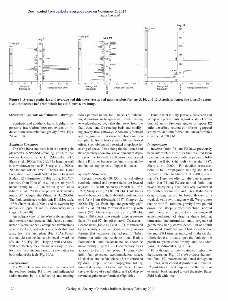
The studied succession contains a posi-tively skewed distribution of grain sizes with a mean of 18.8 mm (coarse pebble), median of 0.28 mm (medium sand), and mode of 0.188 m (fi ne sand). Clasts exhibit both immature and mature textures indicative of a range of prov-enances that have undergone differing amounts of reworking prior to redeposition. Abundant angular and subangular clasts indicate minimal transport and short-lived fl ows. Average grain sizes for each sedimentary log reveal a broad fi ning from NW to SE (Fig. 3B) with logs 6–7 containing the fi nest-grained average (Fig. 3B). This refl ects the fact that logs 6–7 sample the lowest parts of R1, which are fi ner-grained than the upper part (Figs. 3B and 9). Overview graphic logs of stratigraphic units R1 and R2 show two broad coarsening-up cycles (Fig. 3A). However, detailed grain-size plots at the outcrop scale (>360 m) reveal that a coarsening-up trend is only present in R1, while R2 displays a verti-cally unordered grain-size distribution (Fig. 9). The reason for this apparent discrepancy is given by one or two thick, coarse beds that bias graphic sedimentary logs (e.g., Hiscott, 1981; Fig. 3). Coarsening-up patterns are, however, commonly observed at the <10 m scale in both R1 and R2 (Fig. 8). Bed thickening and thin-ning upward at the outcrop (>360 m) scale are unordered in both R1 and R2 (Fig. 9), which is unsurprising given the dominance of lenticular bedding.
The three graphic sedimentary logs in Figure 8 demonstrate the vertical distribution of litho-facies. Logs are hung on a tabular lithofacies 6 unit that occurs near the top of R1 (Fig. 8). Greater lithofacies heterogeneity occurs in the NW and central parts of the study area (Fig. 8). Sandstones and mudstones (lithofacies 1–3) dominate the SE part of the study area, where fewer lithofacies types occur. Mudstone content
increases toward the SE and is generally below 15% (Figs. 3B and 8).
Paleofl ow directions in R1 reveal a poly-modal distribution with dominant fl ows toward the SW and NW, and minor transport toward the NE and SE (Fig. 3A). Paleocurrent directions in R2 are more unimodal, with a dominance of westward-directed currents; however, it should be noted that only small numbers of directions were measured (Fig. 3A).
InterpretationThe heterogeneous lithofacies organization
indicates a disorganized sediment dispersal sys-tem dominated by episodic depositional events. The coarse-grained, positively skewed character of the sediments suggests a spectrum of highly energetic, short-duration gravity fl ows (Walker, 1975; Lowe, 1982) that poured down steep sub-marine terrain.
Deposition is inferred to be relatively proxi-mal throughout the study area with prerift clasts and Miocene contemporaneous reef material originating from an adjacent margin. Paleo-current directions suggest that fl ows were mainly from the eastern margin, adjacent to the Baba Sidri fault (Fig. 3A). The western hanging-wall crest is considered a minor sediment source area, because an almost complete prerift suc-cession is preserved, implying early burial by synrift sediments (Fig. 2).
Fining toward the SE suggests that there was a smaller fl ux of coarse-grained material reach-ing this area, and thus a greater preservation potential of fi ne-grained deposits because fewer erosive fl ows occurred there.
The broad coarsening-up pattern in strati-graphic unit R1 suggests that with time the slope prograded basinward, fl ow magnitudes in-creased, the availability of large prerift clasts increased , and slopes steepened. We speculate that earthquake-induced shaking, catastrophic river fl ooding, and storm-induced remobiliza-tion of shallow-marine (shoreface and shelf) sediments might have triggered the gravity fl ows. The tabular lithofacies 6 bed that occurs at the top of R1 is interpreted to have formed by collapse of the eastern margin (Fig. 9).
The base of stratigraphic unit R2 marks a re-duction in conglomerate grain size during earliest R2 times (Figs. 3A and 9). This is speculatively attributed to a reduction in fault activity, leading to a reduction of paleo-earthquakes and relative sea-level rise. Stratigraphic unit R2 coarsening- and thickening-up patterns are highly disorganized, suggestive of a complex depositional system with localized deposition and erosion linked to allo-cyclic processes. Sharp et al. (2000b) identifi ed a series of prograding deltaic clinoforms from photographs of inaccessible locations positioned
on November 2, 2014gsabulletin.gsapubs.orgDownloaded from

Submarine slope processes in rift-margin basins, Miocene Suez Rift, Egypt
Geological Society of America Bulletin, January/February 2013 119
above the studied succession of this study. These clinoforms demark narrow deltas (<1 km wide). Thus, R2 grain-size and bed thickness patterns may also represent infi lling of accommodation space, and shoaling, followed by localized del-taic progradation and avulsion onto and across the shelf (Sharp et al., 2000b).
Smaller-scale (<10 m) coarsening-upward trends suggest a tendency for increasingly ener-
getic fl ows with time. Such bed confi gura-tions can represent within channel autocylic processes (Pirmez and Imran, 2003) or fault-induced tilting leading to increased slope steep-ness (Wild et al., 2009). Coarsening-up trends cannot be correlated from log to log because of the propensity of channelized beds. Ubiquitous channelization points to an erosive, above-grade slope, prone to frequent avulsion (Samuel et al.,
2003). Submarine channel switching could have been driven by: (1) the presence of multi-ple terrestrial drainages that fed the submarine realm; (2) fault-induced surface tilting leading to fl uvial drainage relocation; (3) localized sub-marine subsidence changing preferential fl ow pathways and rotating previously deposited strata; and (4) downslope channel blockage by slumping and within-channel bar forms.
Cs Pe BoZ BlLog 3
20
40
60
80
100
120
140
160
180
)m(thgi eH
CU/FUPatterns
Lithofacies1 2 3 45 6
Cs Pe BoZ Bl
Log 12
20
40
60
Heigh
t (m)
80
100
120
140
160
CU/FUPatterns
Cs Pe BoZ Bl
Log 10
Heigh
t (m)
20
40
60
80
100
120
140
160
180
CU/FUPatterns Lithofacies
1 2 3 45 6 Lithofacies1 2 3 45 6
n= 204 n= 223
n= 163
Lithofacies 1 Lithofacies 3
Lithofacies 2 Lithofacies 4
KeyLithology
Mudstone
Sandstone
Conglomerate
Lithofacies 5Lithofacies 6
R2R1
R1
R2R1
Logs aligned on laterally extensive conglomerate
Stratigraphic units
Stratigraphic units
Stratigraphic units
SENW
Pie chart key
Figure 8. Summary sedimentary logs and lithofacies charts from northern, central, and southern parts of the study area (logs 3, 10 and 12; Fig. 3). Logs are hung from a rare tabular lithofacies 6 bed. Pie charts correspond to data within each log and show number of beds by lithofacies. N = number of beds. CU/FU—Coarsening up or fi ning up. For grain-size abbreviations, see Figure 3.
on November 2, 2014gsabulletin.gsapubs.orgDownloaded from
Strachan et al.
120 Geological Society of America Bulletin, January/February 2013
Structural Controls on Sediment Pathways
Synthetic and antithetic faults highlight the possible interaction between extension-in-duced submarine relief and gravity fl ows (Figs. 2A and 10).
Antithetic StructuresThe West Baba antithetic fault is a curving (in
plan-view), NNW-SSE–trending structure that extends laterally for >2 km (Moustafa, 1987; Sharp et al., 2000a; Fig. 2A). The hanging wall is downthrown to the E (Sharp et al., 2000a, 2000b) and offsets prerift Thebes and Darat Formations, and synrift Nukhul (units 1–3) and Rudeis (R1) Formations (Table 1; Fig. 10). Off-sets vary from 50 to 60 m at the pre- to synrift unconformity to 0–10 m within synrift units (Sharp et al., 2000a). Reported slickenslides imply 30° oblique slip (Sharp et al., 2000b). The fault terminates within unit R1 (Moustafa, 1987; Sharp et al., 2000b) and is overlain by nonfaulted upper R1 and R2 sedimentary units (Figs. 2A and 10).
An oblique view of the West Baba antithetic fault reveals heterogeneous lithofacies, a domi-nance of lenticular beds, abrupt bed terminations against the fault, and rotation of beds that thin away from the fault plane (Fig. 10A). Paleo-currents close to the fault are bimodal toward the SW and SE (Fig. 3B). Hanging-wall and foot-wall sedimentary rock thicknesses vary up sec-tion, with bed thickness maxima alternating on both sides of the fault (Fig. 10A).
InterpretationThe West Baba antithetic fault had breached
the seafl oor during R1 times and infl uenced sedimentation by: (1) defl ecting and rotating
fl ows parallel to the fault trace; (2) enhanc-ing deposition in hanging-wall lows, leading to wedge-shaped beds that thin away from the fault trace; and (3) rotating beds and modify-ing gravity-fl ow pathways. Anomalous footwall and hanging-wall thickness variations imply a complex fault-slip history with oblique, dextral offset. Such oblique slip resulted in upslope fo-cusing of coeval fl ows along the fault trace and the apparently anomalous development of depo-sition on the footwall. Fault movement ceased during R1 times because the fault is overlain by nonfaulted draping beds of upper R1 strata.
Synthetic StructuresSeveral mesoscale (50–350 m vertical offset)
synthetic normal and reverse faults are located adjacent to the rift boundary (Moustafa, 1987, 1993; Sharp et al., 2000a, 2000b). Fault traces trend subparallel to the Baba-Sidri fault and ex-tend for <1 km (Moustafa, 1987; Sharp et al., 2000b; Fig. 2). Fault dips are generally >60° (Sharp et al., 2000b). Movement is dip slip with minor (8°) oblique slip (Sharp et al., 2000b). Figure 10B shows two steeply dipping reverse faults (F1 and F2) that offset prerift Cretaceous–Eocene units (Table 1). Fault 1 (F1) is truncated by an angular, erosional (karst surface) uncon-formity that juxtaposes faulted prerift Thebes Formation units against depositional Rudeis Formation R1 units that are nonfaulted above the unconformity (Fig. 10B). R1 sedimentary rocks adjacent to the F1 fault plane: (1) completely infi ll fault-generated accommodation space; (2) thicken into the fault plane; (3) are deformed by drag-, drape-, or fault-propagation folding immediately adjacent to the fault plane; (4) pre-serve evidence of stratal tilting; and (5) display several angular uncon formities (Fig. 10B).
Fault 2 (F2) is only partially preserved and juxtaposes prerift units against Rudeis Forma-tion R2 units. Previous studies of upper R2 units described rotated clinoforms, geopetal structures, and intraformational unconformities (Sharp et al., 2000b).
InterpretationReverse faults F1 and F2 have previously
been interpreted as thrusts that resulted from space issues associated with propagation fold-ing of the Baba-Sidri fault (Moustafa, 1987; Sharp et al., 2000b). For detailed cross sec-tions of fault-propagation folding and thrust formation, refer to Sharp et al. (2000b, their fi g. 17). Here, we offer an alternate interpre-tation that F1 and F2 are normal faults that have subsequently been passively overturned by contemporaneous and later Baba-Sidri drag folding caused by broad fl exure of a weak downthrown hanging wall. We propose that prior to F1 rotation, gravity fl ows poured down the steep surface-breaching normal fault plane, infi lling the local hanging-wall accommodation. R1 drag or drape folding, intrastratal unconformities, and divergent bed geometries imply coeval deposition and fault movement. Fault movement had ceased before the end of R1 time, as indicated by the tabular lithofacies 6 unit that drapes the fault tip, the prerift to synrift unconformity, and the under-lying R1 sediments (Fig. 10B).
F2 is thought to have continued higher into the succession (Fig. 10B). We propose that nor-mal fault (F2) movement continued throughout R2 times, with coeval deposition and rotation. F2 postdates F1 and implies that the locus of extension back-stepped toward the major Baba-Sidri fault with time.
05101520Average bed thickness (m)
0
40
80
120
160
200
Bed n
umbe
r 0
Average grain size (mm)
200 400 600
Log 10
* *
05101520Average bed thickness (m)
0
50
100
150
200
Bed n
umbe
r 0
Average grain size (mm)
20025
250
300Log 12
400 600
**
05101520Average bed thickness (m)
0
40
80
120
160
200Be
d num
ber 0
Average grain size (mm)
200 400 600
Log 3
**R1
R2
R1
R2 R2
R1
Stratigraphic units
Stratigraphic units
Stratigraphic units
Figure 9. Average grain size and average bed thickness versus bed number plots for logs 3, 10, and 12. Asterisks denote the laterally exten-sive lithofacies 6 bed from which logs in Figure 8 are hung.
on November 2, 2014gsabulletin.gsapubs.orgDownloaded from

Submarine slope processes in rift-margin basins, Miocene Suez Rift, Egypt
Geological Society of America Bulletin, January/February 2013 121
DISCUSSION
Sedimentary Model of Evolution
Rudeis Formation Unit 1 (R1)Deposition initiated with a spectrum of grav-
ity fl ows, including erosive channelized silty, sandy, and pebbly turbidity currents; unconfi ned sandy and silty turbidity currents; and numer-ous bypassing fl ows (Fig. 11A). Hemipelagic mud deposition occurred at times of minimal coarse-grained sediment input and may refl ect relative sea-level rise. Turbidity current chan-nels were defl ected against faulted seafl oor topog raphy, leading to polymodal paleo currents (Figs. 3B and 11A). The system aggraded and perhaps prograded with time, forming a com-
plex network of heterogeneous, coalescing len-ticular and minor tabular turbidites, debrites, and slumps. Myriad channelized fl ows, with a range of paleofl ow directions, additionally sug-gest multiple point sources, while extensive tabular collapse units imply a line source along the length of the eastern margin. Distinct con-glomerate types with discrete provenances also suggest that a range of terrestrial drainages were located in the northern and central parts of the study area, shedding prerift clasts and Miocene reef detritus offshore from the eastern margin, with a possible minor western sediment source during earliest time (Fig. 11A). The variety of textural maturities in prerift clasts indicates ero-sion and transport through a range of terrestrial environments, including rivers and alluvial fans
for texturally mature clasts, and cliffs and hill-slopes for immature clasts. Our study recorded little evidence of in situ shelf sediment, although Sharp et al. (2000b) inferred several small deltas adjacent to the Baba-Sidri fault system. Sedi-ment staging areas include river mouths, small fan deltas (Sharp et al., 2000b), hillslopes, cliffs, and narrow transient shelves (here we assume shelf widths of <0.5 km, i.e., the distance from slope sequences to the master bounding Baba-Sidri fault). Erosive high-concentration turbid-ity currents and debris fl ows were less frequent in the SE.
Deposition is interpreted to have occurred be-low storm wave base (>100 m), on sub marine slope and basin fl oor environments. Several early active normal faults breached the seafl oor,
Log 1
BPrerift synriftunconformity - karst surface (Thebes Fmn) overlain by upper R1 strata
SW NE100m
Baba-Sidri Fault
Thebes Formation
Overturned hanging wall
Extensive collapse unitLithofacies 6
Basement
Fault 1 (F1)Fault 2 (F2)
Eroded fault plane
Overturned footwall
Sudr FormationMatulla Formation
Drag foldingRudeis Formation unit R1
Rudeis Formation unit R2
NW SENuk
hul F
orm
atio
n (u
nit 3
)R
udei
s Fo
rmat
ion
unit
R1
10m
Local thickening into hanging wall
A
Debrite horizon located on footwall
Anomalous thickness on footwall
Inclined bedding
Onlap
Undeformed bed
HW thickness > FW thickness
Hanging wall
Footwall
Log 8
Log 9
N
C
A
B
0 0.5 1 km
Figure 10. (A) Oblique view of West Baba antithetic fault. HW—hanging wall; FW—footwall. (B) Oblique view of synthetic faults and overlying Rudeis Formation units. Note the diachronous nature of prerift-synrift unconformity. (C) Simplifi ed geologic map showing the location of photos A and B (see Fig. 2 for key).
on November 2, 2014gsabulletin.gsapubs.orgDownloaded from

Strachan et al.
122 Geological Society of America Bulletin, January/February 2013
creating steep, stepped fault-scarp slopes and local hanging-wall depocenters (Fig. 11A). The relief of these structures affected gravity-fl ow dynamics and deposition through the formation of above-grade incisional channels (Kneller, 2003; Samuel et al., 2003) and defl ected fl ows (Edwards et al., 1994). West Baba antithetic and F1 fault movement continued throughout much of R1 times, rotating the seafl oor, creating local-ized sites of subsidence, generating angular un-conformities, and deforming coeval sediments via drag folding (Figs. 10 and 11A). The West Baba antithetic and F1 faults became inactive in later R1 times and were buried by widespread, nonfaulted deposits that formed by collapse of the eastern margin (Fig. 11A).
We suggest that the heterogeneous distribu-tion of facies was controlled by: (1) autocyclic slope-channel processes, such as avulsion, lat-eral migration, and channel breaching; (2) multi-ple terrestrial drainages; (3) myriad gravity-fl ow types; (4) tectonically driven uplift, subsidence, and surface tilting; and (5) multiple gravity-fl ow triggers. The increasing abundance of medium-coarse block (sensu Blair and McPherson, 1999) conglomerates suggests that catastrophic col-lapse of landslide-prone slopes by earthquake shaking became more frequent with time. Con-trols on submarine slope aggradation and progra-dation may have been controlled by increasing earthquake recurrence rates or relative sea-level fall. Evidence of enhanced subsidence leading to sediment starvation and mudstone depo sition (Prosser, 1993) during this time is absent and is instead completely outpaced by high sedimenta-tion rates. Water depths remained below storm wave base throughout.
Rudeis Formation Unit 2 (R2)Westward-directed gravity flows accom-
pa nied widespread turbidite sand and minor hemipelagic mud deposition in early R2 times (Fig. 11B). A succession of increasingly large-
F2West Baba Antithetic and F1 faults are inactive
N
1 km
West Baba Antithetic Fault
F1F2
Baba-Sidri Fault
R1 - Early to mid
R1- Latest
Uplift
Sea level Multidirectional gravity flows
Dominantly westerly directed flows
Large-scale collapse of eastern margin
Rudeis Formation sediments
Prerift-synrift unconformities
Subsidence
Baba-Sidri Fault
R2 - Early
R2 - Late
Uplift
Uplift&rotationof synriftstrata
Rudeis Formation sediments
Drag folding by ongoing F2 movement
Rudeis Formation sediments
F2 is inactive
Subsidence
F2
Westerly directed gravity flows
Baba-Sidri Fault
Baba-Sidri Fault
Relative sea- level fall
River incision
Westerly directed gravity flows
Delta progradation
Subsidence
A
B
Small reefat rivermouth
Figure 11. (A) Schematic diagrams show-ing gravity-fl ow pathways and bathymetry evolution from unit R1 (divided into early to mid, and latest stages). (B) Schematic diagrams showing gravity-fl ow pathways and bathymetry evolution from unit R2 (di-vided into early and late stages). Small patch reefs are included in several cartoons; their positions are very speculative. The cartoons depicted here show the structural reinter-pretation described in this paper. We recog-nize that the data may also be interpreted as a faulted monocline (for faulted monocline cross sections, see Sharp et al., 2000a, 2000b).
on November 2, 2014gsabulletin.gsapubs.orgDownloaded from
Submarine slope processes in rift-margin basins, Miocene Suez Rift, Egypt
Geological Society of America Bulletin, January/February 2013 123
magnitude erosional gravity fl ows (including turbidity currents, debris fl ows, cogenetic fl ows and slumps) originating from the eastern mar-gin followed (Fig. 3). Beds are composed of medium sand– to boulder-sized prerift clasts and Miocene reef fragments possibly derived from river mouths, alluvial planes, and deltas on a steep uplifting hinterland. Sharp et al. (2000a, 2000b) interpreted deltaic clinoforms as preserving evidence of shallowing-up trends in latest R2 times. The deltaic clinoforms of Sharp et al. (2000a, 2000b) are interpreted here to have prograded across R1 and early R2 sediments that infi lled fault-generated accom-modation, generating a narrow (<0.5 km) depo-sitional shelf (Fig. 11B).
Deposition is thought to have occurred in submarine slope and base-of-slope environ-ments until latest R2 time (Fig. 11B). Sub-marine slope and base-of-slope water depths were below storm wave base. Early R2 bathym-etry was characterized by a faulted margin, with normal fault F2 offsets creating localized over-steepening, hanging-wall subsidence, surface rotation, and penecontemporaneous drag fold-ing of sediments (Fig. 11B). Later R2 bathy-metric relief may have become subdued as fault F2 movement ceased and accommodation was infi lled. It is likely that the submarine slope environment shallowed, but limited outcrop prevents identifi cation of reworked shelf strata. Deltaic environments dominated latest R2 time, with a series of successively rotated prograding clinoforms (Sharp et al., 2000a, 2000b). Clino-form rotation resulted from ongoing Baba-Sidri fault deformation and drag folding that con-tinued well after Rudeis Formation deposition (Moustafa, 1987).
The heterogeneous distribution of facies re-sulted from multiple fl ow processes, gravity-fl ow triggers, and several terrestrial sources. The transition from medium to coarse block conglomerates within upper R1 units to sand-stone and pebble conglomerates within lower R2 resulted from a rearrangement of mesoscale faults whereby the antithetic and F1 faults be-came inactive and draped by undeformed over-lying units, but offset and deformation of F2 and the Baba-Sidri fault continued (Fig. 11). Active extension back-stepped and was accommodated by fault F2 and the Baba-Sidri fault, leading to development of a larger and shallower basin with time.
Comparison of Rift-Margin Deposits
We compared deposit characteristics from 16 rift-margin basin sedimentological case studies (Fig. 12) to put north Wadi Baba results into context. Compiled case studies include ancient
outcrop (e.g., Suez, East Greenland, Woodlark Rift, East Kenya) and modern subaqueous data (e.g., Corinth, Lake Baikal, Lake Malawi, Lake Tanganyik) from marine and lacustrine environ-ments, and rift and backarc rift settings. Despite the variety of locations and tectonic settings, all examples preserve proximal subaqueous syn-rift strata located immediately adjacent to rift-border faults, thus providing valuable insights into facies relationships and paleoenvironmen-tal reconstructions. The following sedimen-tological and paleogeographic attributes were compared and include grain size (maximum, minimum, and mean), total stratal thickness, shelf widths (maximum, minimum, and mean), water depths, dominant grading type (e.g., nor-mal, reverse, etc.), vertical grain-size trends, dominant bed shape, lateral extent of beds, and sediment feeder types (e.g., point, line, multiple-point sources). Where absolute grain-size values are absent, descriptive Udden-Wentworth scale terms are converted to numeric values (e.g., silt to 0.0625 mm), and arithmetic means have been calculated. We recognize that arithmetic means are not representative of skewed grain-size distributions, such as at north Wadi Baba; however, without detailed published grain-size data, these cannot be determined. Shelf widths, water depths, and sediment feeder types (sensu Reading and Richards, 1994) have been directly measured in modern subaqueous locations and are inferred from outcrops, thereby introducing unknown errors. The nature of bedding, vertical grain-size trends, and bed shape measurements were gleaned from published descriptions and fi gures (Fig. 12).
Sedimentological characteristics are here evaluated before paleogeographic and phys-iographic qualities (Figs. 12A–12D). A wide range of synrift stratal thicknesses was noted, from 60 m to 9 km (Fig. 12A). All thicknesses are from partially preserved or measured sec-tions and imply there is no relationship among rift location, tectonic setting, and environmen-tal setting. Vertical outcrop grain-size trends exhibit a heterogeneous range of patterns, in-cluding fi ning-up, coarsening-up, unordered, coarsening-up to unordered, coarsening-up to fi ning-up, and fi ning-up to coarsening-up to un-ordered (Fig. 12A). Outcrop-scaled grain-size motifs are highly variable, even within single rifts, for example, four different patterns are rec-ognized along the Suez Rift (Gupta et al., 1999; Young et al., 2000, 2002; Leppard and Gaw-thorpe, 2006; Fig. 12A). Our review suggests that thicker synrift fi lls have a tendency toward unordered stratigraphic motifs, while thinner fi lls exhibit more ordered patterns (Fig. 12A). North Wadi Baba and the Wollaston Forland Group, East Greenland (Surlyk, 1978, 1984),
are signifi cantly coarser grained than all other examples (Figs. 12B and 12C), suggesting that sediment delivered to those sites had undergone minimal reworking, as a consequence of nomi-nal transport distances, short residence times, and deposition by high-energy catastrophic gravity fl ows. Nongraded beds are the dominant bed type in most studies, except Lake Malawi (Wells et al., 1999), where normally graded turbidites are dominant. A wide variety of bed geometries is noted, with mixed sheet and len-ticular shapes most common. This refl ects the range of subenvironments and processes pre-served in synrift strata, including subaqueous slopes and base of slopes. Furthermore, rugged offshore topography and complex terrain adja-cent to border faults, such as is observed in Lake Malawi (Johnson et al., 1995), are likely to re-sult in highly varied bed shapes. Lenticular bed widths range from 1 m to 2 km, and sheets range from 500 m to 40 km (Fig. 12D). Variation in widths refl ects scale of study and interpreted scales of fl ow confi nement related to different processes and subenvironments (Fig. 12D). The fl oor of Lake Malawi typifi es the latter, with a complex suite of coarse-grained lenticular beds deposited in transient subenvironments, includ-ing narrow, <25-m-wide drowned fl uvial chan-nels mantled by deep-water hemipelagites, and 1-km-wide sublacustrine turbidity current chan-nels (Scholz et al., 1990).
Paleogeographic reconstructions from out-crop data are essentially interpretive, and re-constructed physiographic subenvironment measurements, such as shelf widths, are limited in scope. In our comparison, we distinguish modern from ancient outcrop data (Figs. 12E–12H). Modern and ancient case studies show a variety of sediment feeder systems within each rift, including single-point sources, multiple-point sources, and mixed (multiple point and line) feeder systems (Fig. 12E). Depositional systems fed exclusively by line sources are absent (Fig. 12E). The complexity of feeder systems is exemplifi ed by modern-day Corinth graben geomorphology (Ferentinos et al., 1988), where mixed (line and multiple point) sources result in three depositional environments: (1) shelf-slope prone to collapse; (2) river-linked canyons and terminal lobes; and (3) delta fronts. Modern subaqueous data reveal a wide range of water depths that do not correlate with preserved sediment thicknesses and maximum grain sizes (e.g., Fig. 12F). This is counter to many sediment transport paradigms; however, we suggest that deposition in rift-margin set-tings is extremely immature and that grain and clast sizes refl ect rock types in adjacent uplifting drainage basins, terrestrial sedimentary processes , and climate, and any preconditioning of the
on November 2, 2014gsabulletin.gsapubs.orgDownloaded from

Strachan et al.
124 Geological Society of America Bulletin, January/February 2013
juxtaposed rock masses to rock avalanches and landslides. Shelf widths vary between rifted margins, but they are generally less than 2 km (Figs. 12G–12H). The narrowness of shelves is attributed to proximity to active fault-generated scarps that are manifested as steep onshore and offshore slopes and impede generation of wide shelves. An inverse correlation between shelf widths and maximum grain size (Figs. 12G–12H) further suggests that, where present, even as narrow slivers, shelves are highly effective at trapping coarse-grained sediment. Following this corollary, we suggest that a shelf was virtu-ally absent in north Wadi Baba during much of Rudeis Formation times.
Rift-margin basin sedimentary successions preserve immature proximal sediments, mainly deposited by gravity-fl ow processes, that are transported through steep fault-controlled terrain. Gravity flows can transport coarse sediment (pebble to block) offshore, with the coarsest material shed directly onto subaque-ous slopes. Such steep offshore topography probably impedes the formation of fan deltas (Johnson et al., 1995). However, where present, shelves are effective traps for very large clasts and thus promote development of fan deltas. Ravnås and Steel (1998) hypothesized that the coarsest sedimentary units would be trapped in rift-margin basins. This is consistent with our observations.
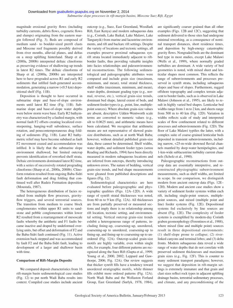
A schematic matrix shows the range of rock and sediment types and bed geometries encoun-tered in the reviewed case studies (Fig. 13). Depositional systems in rift-border basins are remarkably varied, both along entire rifts and within single fault blocks. Thus, we envisage a spectrum of contemporaneous sedimentary re-sponses to rifting within each basin, varying as a function of shelf widths, sediment fl ow types, fl ow competencies, proximity to faults, and slope gradients. The synrift sedimentary rocks at north Wadi Baba represent a particularly coarse-grained example, dominated by complex con-fi ned coalescing gravity-fl ow deposits deposited in a rugged submarine slope and base-of-slope environment. Our comparison is a fi rst attempt to understand the range of processes and prod-ucts in rift-margin basins and requires detailed quantitative grain-size and physiographic data, which are often unavailable, to enable more ro-bust comparisons.
CONCLUSIONS
Our high-resolution lithofacies study of north Wadi Baba reveals a coarsening-up to un ordered synrift succession, dominated by coarse-grained (coarse-pebble sized) heterogeneous, lenticular beds forming coalescing channelized turbidites ,
Maximum grain size (Modified
Udden-Wentworth) Coar
se bo
ulder
sV
Coar
se bo
ulder
sFin
e Bloc
kMe
dium
Bloc
k
Coar
se B
lock
V Co
arse
Bloc
k
01
23
4Sh
elf w
idth
(km
)
H
V Fi
ne s
and
Fine
san
dM
ediu
m s
and
Coar
se s
and
V Co
arse
san
d
Minimum grain size (Udden-Wentworth)
01
23
4Sh
elf w
idth
(km
)
G
Coar
se bo
ulder
sV
Coar
se bo
ulder
sFin
e Bloc
kMe
dium
Bloc
k
Coar
se B
lock
V Co
arse
Bloc
k
Maximum grain size (Modified
Udden-Wentworth)
050
010
00W
ater
dep
th (m
)
F
Total thickness (km) 02468
Point-source
Multiple-point-source
Line-source
Mixed-source
Sedi
men
t Fee
der t
ype
E
12346789
Fining-up
Coarsening-up
Unordered
Coarsening-up-unordered
Coarsening-up-Fining-up
Fining-up-Coarsening-up-Unordered
5 Total thickness (km)
Verti
cal g
rain
size
dist
ribut
ion
A
Suez
East Greenland
Corinth
Lake Baikal
East Africa Rift
Woodlark Rift
Maximum grain size (Modified Udden-Wentworth) Co
arse
bould
ers
V Co
arse
bould
ers
Fine B
lock
Mediu
m Bl
ock
Coar
se B
lock
V Co
arse
Bloc
k
Loca
tion
B
Suez
East Greenland
Corinth
Lake Baikal
East Africa Rift
Woodlark Rift
V Fin
e san
dFin
e san
dMe
dium
sand
Coars
e san
d
V Co
arse s
and
Minimum grain size (Udden-Wentworth)
Loca
tion
C
East
Gree
nland
East
Afric
a Rift
North
Wad
i Bab
a
Suez
Corin
th
Lake
Baik
al
Woo
dlark
Rift
Key
Wid
th (k
m)
Width (km)
010
2030
40010203040
D
Lenti
cular
beds
(blac
k)
Tabu
lar be
ds (g
ray)
Mode
rn da
ta (g
ray)
Outcr
op da
ta (b
lack)
Mode
rn da
ta (g
ray)
Outcr
op da
ta (b
lack)
Mode
rn da
ta (g
ray)
Outcr
op da
ta (b
lack)
Mode
rn da
ta (g
ray)
Outcr
op da
ta (b
lack)
Fig
ure
12. (
A–H
) Sum
mar
y pl
ots
of d
epos
it c
hara
cter
isti
cs fr
om 1
6 ri
ft-m
argi
n ba
sin
sedi
men
tolo
gica
l cas
e st
udie
s, in
clus
ive
of n
orth
Wad
i Bab
a da
ta a
nd S
urly
k (1
978,
198
4);
Fer
enti
nos
et a
l. (1
988)
; Sc
holz
et
al. (
1990
); P
apat
heod
orou
and
Fer
enti
nos
(199
3);
Gup
ta e
t al
. (19
99);
Nel
son
et a
l. (1
999)
; W
ells
et
al. (
1999
); Y
oung
et
al. (
2000
, 200
2);
Rob
erts
on e
t al
. (20
01);
Col
man
et
al. (
2003
); L
eppa
rd a
nd G
awth
orpe
(20
06);
San
eyos
hi e
t al
. (20
06);
and
Bac
kert
et
al. (
2010
). (
A) T
otal
str
atal
thi
ckne
ss v
s. v
erti
cal g
rain
-si
ze d
istr
ibut
ion.
(B
–C)
Max
imum
and
min
imum
gra
in s
ize
vs. l
ocat
ion.
(D
) B
ed w
idth
s di
stin
guis
hed
by le
ntic
ular
(bl
ack)
vs.
tab
ular
(gr
ay)
geom
etri
es. (
E)
Tota
l sed
imen
t th
ickn
ess
vs. s
edim
ent
feed
er t
ype.
(F
) M
axim
um g
rain
siz
e vs
. wat
er d
epth
. (G
–H)
Min
imum
and
max
imum
gra
in s
ize
vs. s
helf
wid
ths.
In
plot
s E
–H, m
oder
n su
baqu
eous
da
ta (
in g
ray)
are
dis
ting
uish
ed f
rom
out
crop
dat
a (i
n bl
ack)
.
on November 2, 2014gsabulletin.gsapubs.orgDownloaded from
Submarine slope processes in rift-margin basins, Miocene Suez Rift, Egypt
Geological Society of America Bulletin, January/February 2013 125
slumps, debrites, and sheets deposited on de-forming submarine slopes and basin fl oor. Flows are composed of prerift clasts and con-temporaneous reef fragments predominantly originating from an uplifted eastern hinterland. Myriad clast types exhibit both immature and mature textures indicative of a range of prov-enances that have undergone differing amounts of reworking prior to redeposition. Multiple ter-restrial drainages likely debouched onto faulted offshore slopes with complex terrain and fed fan deltas that developed on narrow shelves (<0.5 km width). Steep subaerial topography of the adjacent margin may have also supplied submarine slopes with prerift rock avalanche and landslide-derived clasts. Mud deposition was rare but occurred during periods devoid of coarse-grained deposition.
Ongoing rift-related faulting during Rudeis Formation times had a profound infl uence on synrift sediments by controlling the locus of
subsidence and gravity base level, together with changing local slope gradients and hence gravity-fl ow pathways. Mesoscale faults became inactive during Rudeis Formation times, with defor ma tion focused on the master bounding Baba-Sidri fault. Active faulting thus migrated toward the rift-bounding Baba-Sidri fault, lead-ing to development of a larger basin with time.
The comparison of rift-margin basin sedi-mentological case studies reveals a remark-ably varied array of synrift fi lls, with very few preferential grain-size or bed-type trends (Fig. 12). In our comparison, only three obvious re-lationships were noted: (1) the tendency in thick synrift successions toward an unordered vertical grain-size distribution; (2) a dominance of non-graded beds in most studies; and (3) an inverse relationship between maximum clast size and shelf width. Rift-margin basins mainly contain proximal gravity-fl ow deposits, deposited on or near steep subaqueous slopes and sourced from
uplifting adjacent drainages. There appear to be few obvious sedimentary differences between marine and lacustrine locations, and rift and backarc settings. Few studies in our comparison provided quantitative grain-size and physio-graphic data due to the differing approaches and fi delity of records. Ancient outcrops provide the opportunity for detailed grain-size and litho-facies analyses, as presented here, while modern subaqueous studies provide useful information about physiography.
We propose a new model to capture the spectrum of contemporaneous sedimentary responses to rifting within rift-margin basins, varying as a function of shelf width, slope gra-dient, maximum grain size, and textural matu-rity (Fig. 13). North Wadi Baba is a particularly coarse-grained end member, deposited on steep slopes, with a very narrow shelf. It was also prone to periods of mud deposition and there-fore responded abruptly to changes in sedimen-tation in space and time.
ACKNOWLEDGMENTS
We would like to dedicate this work to the late Sayed Gooda, who, together with his brother Gamal Gooda, provided us with invaluable logistical sup-port and wonderful company. This study was part of stage 1 of The Rift Analogue Project (TRAP), and we thank our sponsors ConocoPhillips and Statoil. Chris Ott is thanked for his valuable assistance in the fi eld. Timothy Debacker is thanked for his input and feed-back, particularly with the tectonic re-interpretation. Louise Cotterall’s assistance in drafting Figures 4 and 10 is gratefully acknowledged. Jaco Baas, Chris Jackson, and Sanjeev Gupta provided helpful feed-back on early versions of the paper. Reviewers Finn Surlyk and Anne Bernhardt, and Associate Editor Henning Dypvik are all thanked for their thoughtful and constructive reviews, which helped to improve the manuscript.
REFERENCES CITED
Abreu, V., Sullivan, M., Pirmez, C., and Mohrig, D., 2003, Lateral accretion packages (LAPS): An important res-ervoir element in deep water sinuous channels: Ma-rine and Petroleum Geology, v. 20, p. 631–648, doi:10.1016/j.marpetgeo.2003.08.003.
Baas, J.H., 2004, Conditions for formation of massive tur-biditic sandstones by primary depositional process: Sedimentary Geology, v. 166, p. 293–310, doi:10.1016/j.sedgeo.2004.01.011.
Backert, N., Ford, M., and Malartre, F., 2010, Architecture and sedimentology of the Kerinitis Gilbert-type fan delta, Corinth Rift, Greece: Sedimentology, v. 57, p. 543–586, doi:10.1111/j.1365-3091.2009.01105.x.
Blair, T.C., and McPherson, J.G., 1999, Grain-size textural classifi cation of coarse sedimentary particles: Journal of Sedimentary Research, v. 69, p. 6–19.
Bluck, B.J., 1967, Deposition of some Upper Old Red Sand-stone conglomerates in the Clyde area: A study in the signifi cance of bedding: Scottish Journal of Geology, v. 3, p. 139–167, doi:10.1144/sjg03020139.
Bosence, D.W.J., 1998, Stratigraphic and sedimentological models of rift basins, in Purser, B.H., and Bosence, D.W.J., eds., Sedimentation and Tectonics of Rift Ba-sins: Red Sea-Gulf of Aden: London, Chapman & Hall, p. 9–25.
Maximum Grain sizeTe
xtur
al m
atur
ity
Slope gradient
Shelf
wid
ths
> 30 m0.25 mm
Imma
ture
Matur
eDirec
t offsh
ore
sediment
shedd
ing
Steep Steeper
04 k
m
Sediment
trappe
d
in delta
s
Key
Sandstone
Mudstone Clast-supported conglomerate
Matrix-supported conglomerate
Contortion
SlumpingSiltstone
Pebbly sandstone
Figure 13. Schematic matrix showing the range of rift-margin basin sedimentary response types encountered in our comparison plotted as a function of shelf widths, slope gradient, maximum grain size, and textural maturity. North Wadi Baba would plot toward the bottom right-hand corner.
on November 2, 2014gsabulletin.gsapubs.orgDownloaded from
Strachan et al.
126 Geological Society of America Bulletin, January/February 2013
Bouma, A.H., 1962, Sedimentology of Some Flysch Deposits; A Graphic Approach to Facies Interpretation: Amster-dam, Elsevier, 167 p.
Colman, S.M., Karabanov, E.B., and Nelson, C.H., 2003, Quaternary sedimentation and susbidence history of Lake Baikal, Siberia, based on seismic stratigraphy and coring: Journal of Sedimentary Research, v. 73, p. 941–956, doi:10.1306/041703730941.
Dasgupta, P., 2003, Sediment gravity fl ow—The conceptual problems: Earth-Science Reviews, v. 62, p. 265–281, doi:10.1016/S0012-8252(02)00160-5.
Ebinger, C.J., 1989, Geometric and kinematic development of border faults and accommodation zones, Kivu-Rusizi Rift, Africa: Tectonics, v. 8, p. 117–133, doi:10.1029/TC008i001p00117.
Edwards, D.A., Leeder, M.R., Best, J.L., and Pantin, H.M., 1994, On experimental refl ected density currents and the interpretation of certain turbidites: Sedimentol-ogy, v. 41, p. 437–461, doi:10.1111/j.1365-3091.1994.tb02005.x.
El Azabi, M.H., and El Araby, A., 2007, Depositional frame-work and sequence stratigraphic aspects of the Coni-acian-Santonian mixed siliciclastic/carbonate Matulla sediments in Nezzazat and Ekma blocks, Gulf of Suez, Egypt: Journal of African Earth Sciences, v. 47, p. 179–202, doi:10.1016/j.jafrearsci.2007.02.002.
Elliott, T., 2000, Megafl ute erosion surfaces and the initia-tion of turbidite channels: Geology, v. 28, p. 119–122, doi:10.1130/0091-7613(2000)28<119:MESATI>2.0.CO;2.
Ferentinos, G., Papatheodorou, G., and Collins, M.B., 1988, Sediment transport processes on an active submarine fault escarpment: Gulf of Corinth, Greece: Marine Geology, v. 83, p. 43–61, doi:10.1016/0025-3227(88)90051-5.
Garfunkel, Z., and Bartov, Y., 1977, The tectonics of the Suez Rift: Geological Survey of Israel Bulletin, v. 71, p. 1–41.
Gawthorpe, R.L., and Leeder, M.R., 2000, Tectono-sedi-mentary evolution of active extensional basins: Basin Research, v. 12, p. 195–218, doi:10.1046/j.1365-2117.2000.00121.x.
Gawthorpe, R.L., Sharp, I., Underhill, J.R., and Gupta, S., 1997, Linked sequence stratigraphic and structural evolution of propagating normal faults: Geology, v. 25, p. 795–798, doi:10.1130/0091-7613(1997)025<0795:LSSASE>2.3.CO;2.
Gupta, S., Underhill, J.R., Sharp, I.R., and Gawthorpe, R.L., 1999, Role of fault interactions in controlling syn-rift sediment dispersal patterns: Miocene, Abu Alaqa Group, Suez Rift, Sinai, Egypt: Basin Research, v. 11, p. 167–189, doi:10.1046/j.1365-2117.1999.00300.x.
Hesse, R., Klaucke, I., Khodabakhsh, S., Piper, D.J.W., and Ryan, W.B.F., 2001, Sandy submarine braid plains: Potential deep-water reservoirs: American Association of Petroleum Geologists Bulletin, v. 85, p. 1499–1521.
Hiscott, R., 1981, Deep-sea fan deposits in the Macigno For-mation (Middle-Upper Oligocene) of the Gordana Val-ley, Northern Apennines, Italy—Discussion: Journal of Sedimentary Petrology, v. 51, p. 1015–1021.
Johnson, T.C., Wells, J.D., and Scholz, C.A., 1995, Deltaic sedimentation in a modern rift lake: Geological Society of America Bulletin, v. 107, p. 812–829, doi:10.1130/0016-7606(1995)107<0812:DSIAMR>2.3.CO;2.
Kane, I.A., McCaffrey, W.D., and Martinsen, O.J., 2009, Allo genic vs. autogenic controls on megafl ute forma-tion: Journal of Sedimentary Research, v. 79, p. 643–651, doi:10.2110/jsr.2009.072.
Khalil, S.M., and McClay, K.R., 2001, Tectonic evolution of the NW Red Sea–Gulf of Suez rift system, in Wilson, R.C.L., Whitmarsh, R.B., Taylor, B., and Froitzheim, N., eds., Non-Volcanic Rifting of Continental Margins: A Comparison from Land and Sea: Geological Society of London Special Publication 187, p. 453–473.
Kneller, B., 1995, Beyond the turbidite paradigm; physical models for deposition of turbidites and their implica-tions for reservoir prediction, in Hartley, A.J., and Prosser, D.J., eds., Characterisation of Deep Marine Clastic Systems: Geological Society of London Spe-cial Publication 94, p. 31–49.
Kneller, B., 2003, The infl uence of fl ow parameters on turbi-dite slope channel architecture: Marine and Petro leum
Geology, v. 20, p. 901–910, doi:10.1016/j.marpetgeo.2003.03.001.
Leeder, M.R., and Gawthorpe, R.L., 1987, Sedimentary models for extensional tilt-block/half-graben ba-sins, in Coward, M.P., Dewey, J.F., and Hancock, P.L., eds., Continental Extensional Tectonics: Geo-logical Society of London Special Publication 28, p. 139–152.
Leeder, M.R., Mack, G.H., and Salyards, S.L., 1996, Axial-transverse fluvial interactions in half-graben: Plio-Pleistocene Palomas Basin, southern Rio Grande Rift, New Mexico, USA: Basin Research, v. 8, p. 225–241, doi:10.1046/j.1365-2117.1996.00192.x.
Leppard, C.W., and Gawthorpe, R.L., 2006, Sedimentology of rift climax deep water systems; Lower Rudeis For-mation, Hammam Faraun fault block, Suez Rift, Egypt: Sedimentary Geology, v. 191, p. 67–87, doi:10.1016/j.sedgeo.2006.01.006.
Locat, J., and Lee, H.J., 2002, Submarine landslides: Ad-vances and challenges: Canadian Geotechnical Jour-nal, v. 39, p. 193–212, doi:10.1139/t01-089.
Lowe, D.R., 1982, Sediment gravity fl ows: II. Depositional models with special reference to the deposits of high- density turbidity currents: Journal of Sedimentary Petrol ogy, v. 52, p. 279–297.
Mack, G.H., and Leeder, M.R., 1999, Climatic and tectonic controls on alluvial-fan and axial-fl uvial sedimentation in the Plio-Pleistocene Palomas half graben, southern Rio Grande Rift: Journal of Sedimentary Research, v. 69, p. 635–652.
Mack, G.H., Leeder, M.R., and Perez-Arlucea, M., 2009, Late Neogene rift-basin evolution and its relation to normal fault history and climate change along the southwestern margin of the Gerania Range, central Greece: Geological Society of America Bulletin, v. 121, p. 907–918, doi:10.1130/B26337.1.
Malpas, J.A., Gawthorpe, R.L., Pollard, J.E., and Sharp, I.R., 2005, Ichnofabric analysis of the shallow ma-rine Nukhul Formation (Miocene) Suez Rift, Egypt: Implications for depositional processes and sequence stratigraphic evolution: Palaeogeography, Palaeoclima-tology, Palaeoecology, v. 215, p. 239–264, doi:10.1016/j.palaeo.2004.09.007.
Moustafa, A.R., 1976, Block faulting in the Gulf of Suez, in Fifth Exploration Seminar: Cairo, Egypt, Egyptian General Petroleum Corporation, p. 35.
Moustafa, A.R., 1987, Drape folding in the Baba-Sidri area, eastern side of the Suez Rift: Egypt Journal of Geol-ogy, v. 31, p. 15–27.
Moustafa, A.R., 1993, Structural characteristics and tec-tonic evolution of the east-margin blocks of the Suez Rift: Tectonophysics, v. 223, p. 381–399, doi:10.1016/0040-1951(93)90146-B.
Mulder, T., and Alexander, J., 2001, The physical character of subaqueous sedimentary density fl ows and their de-posits: Sedimentology, v. 48, p. 269–299, doi:10.1046/j.1365-3091.2001.00360.x.
Nelson, C.H., Karabanov, E.B., Colman, S.M., and Escutia , C., 1999, Tectonic and sediment supply control of deep rift lake turbidite systems: Lake Baikal, Russia: Geology, v. 27, p. 163–166, doi:10.1130/0091-7613(1999)027<0163:TASSCO>2.3.CO;2.
Nemec, W., and Steel, R.J., 1984, Alluvial and coastal con-glomerates; their signifi cant features and some com-ments on gravelly mass-fl ow deposits, in Koster, E.H., and Steel, R.J., eds., Sedimentology of Gravels and Conglomerates: Calgary, Canada, Canadian Society of Petroleum Geologists, p. 1–31.
Papatheodorou, G., and Ferentinos, G., 1993, Sedimentation processes and basin-fi lling depositional architecture in an active asymmetric graben: Strava graben, Gulf of Corinth, Greece: Basin Research, v. 5, p. 235–253, doi:10.1111/j.1365-2117.1993.tb00069.x.
Pirmez, C., and Imran, J., 2003, Reconstruction of turbid-ity currents in Amazon channel: Marine and Petroleum Geology, v. 20, p. 823–849, doi:10.1016/j.marpetgeo.2003.03.005.
Prosser, S., 1993, Rift-related linked depositional systems and their seismic expression, in Williams, G.D., and Dobb, A., eds., Tectonics and Seismic Sequence Stra-tigraphy: Geological Society of London Special Publi-cation 71, p. 35–66.
Pyles, D.R., Jennette, D.C., Tomasso, M., Beaubouef, R.T., and Rossen, C., 2010, Concepts learned from a 3D outcrop of a sinuous slope channel complex: Beacon Channel Complex, Brushy Canyon Formation, West Texas, USA: Journal of Sedimentary Research, v. 80, p. 67–96, doi:10.2110/jsr.2010.009.
Ravnås, R., and Steel, R.J., 1998, Architecture of marine rift-basin successions: American Association of Petro-leum Geologists Bulletin, v. 82, p. 110–146.
Reading, H.G., and Richards, M., 1994, Turbidite systems in deep-water basin margins classifi ed by grain-size and feeder system: American Association of Petroleum Geol ogists Bulletin, v. 78, p. 792–822.
Robertson, A.H.F., Awadallah, S.A.M., Gerbaudo, S., Lacksche witz, K.S., Monteleone, B.D., Sharp, T.R., and Party, T.S.S., 2001, Evolution of the Miocene–Recent Woodlark Rift Basin, SW Pacific, inferred from sediments drilled during Ocean Drilling Program Leg 180, in Wilson, R.C.L., Whitmarsh, R.B., Taylor, B., and Froitzheim, N., eds., Non-Volcanic Rifting of Continental Margins: A Comparison of Evidence from Land and Sea: Geological Society of London Special Publication 187, p. 335–372.
Robson, D.A., 1971, The structure of the Gulf of Suez (clys-mic) rift, with special reference to the eastern side: Journal of the Geological Society of London, v. 127, p. 247–271, doi:10.1144/gsjgs.127.3.0247.
Samuel, A., Kneller, B., Raslan, S., Sharp, A., and Parsons, C., 2003, Prolifi c deep-marine slope channels of the Nile Delta, Egypt: American Association of Petroleum Geologists Bulletin, v. 87, p. 541–560, doi:10.1306/1105021094.
Samuel, M.D., Ismail, A.A., Akarish, A.I.M., and Zaky, A.H., 2009, Upper Cretaceous stratigraphy of the Gebel Somar area, north-central Sinai, Egypt: Creta-ceous Research, v. 30, p. 22–34, doi:10.1016/j.cretres.2007.12.001.
Saneyoshi, M., Nakayama, K., Sakai, T., Sawada, Y., and Ishida, H., 2006, Half graben filling processes in the early phase of continental rifting: The Miocene Namurungule Formation of the Kenya Rift: Sedimen-tary Geology, v. 186, p. 111–131, doi:10.1016/j.sedgeo.2005.11.012.
Scholz, C.A., Rosendahl, B.R., and Scott, D.L., 1990, De-velopment of coarse-grained facies in lacustrine rift basins: Examples from East Africa: Geology, v. 18, p. 140–144, doi:10.1130/0091-7613(1990)018<0140:DOCGFI>2.3.CO;2.
Schutz, K.I., 1994, Structure and stratigraphy of the Gulf of Suez, Egypt, in Landon, S.M., ed., Interior Rift Basins: American Association of Petroleum Geologists Mem-oir 59, p. 57–96.
Sellwood, B.W., and Netherwood, R.E., 1984, Facies evolu-tion in the Gulf of Suez area: Sedimentation history as an indicator of rift initiation and development: Modern Geology, v. 9, p. 43–69.
Sharp, I.R., Gawthorpe, R.L., Armstrong, B., and Underhill, J.R., 2000a, Propagation history and passive rotation of mesoscale normal faults: Implications for synrift stratigraphic development: Basin Research, v. 12, p. 285–305, doi:10.1046/j.1365-2117.2000.00132.x.
Sharp, I.R., Gawthorpe, R.L., Underhill, J.R., and Gupta, S., 2000b, Fault-propagation folding in extensional settings: Examples of structural style and synrift sedimentary response from the Suez Rift, Sinai, Egypt: Geological Society of America Bulletin, v. 112, p. 1877–1899, doi:10.1130/0016-7606(2000)112<1877:FPFIES>2.0.CO;2.
Surlyk, F., 1978, Submarine fan sedimentation along fault scarps on tilted fault blocks (Jurassic-Cretaceous bound-ary, East Greenland): Grønlands Geologiske Under-søgelse, v. 128, p. 1–108.
Surlyk, F., 1984, Fan-delta to submarine fan conglomerates of the Volgian-Valanginian Wollaston Forland Group, East Greenland, in Koster, E.H., and Steel, R.J., eds., Sedimentology of Gravels and Conglomerates: Calgary, Canada, Canadian Society of Petroleum Geologists, p. 359–382.
Walker, R.G., 1975, Generalized facies models for resedi-mented conglomerates of turbidite association: Geo-logical Society of America Bulletin, v. 86, p. 737–748, doi:10.1130/0016-7606(1975)86<737:GFMFRC>2.0.CO;2.
on November 2, 2014gsabulletin.gsapubs.orgDownloaded from

Submarine slope processes in rift-margin basins, Miocene Suez Rift, Egypt
Geological Society of America Bulletin, January/February 2013 127
Wells, J.T., Scholz, C.A., and Soreghan, M.J., 1999, Processes of sedimentation on a lacustrine border-fault margin: Interpretation of cores from Lake Malawi, East Africa: Journal of Sedimentary Research, v. 69, p. 816–831.
Wild, R., Flint, S.S., and Hodgson, D.M., 2009, Strati-graphic evolution of the upper slope and shelf edge in the Karoo Basin, South Africa: Basin Research, v. 21, p. 502–527, doi:10.1111/j.1365-2117.2009.00409.x.
Young, M.J., Gawthorpe, R.L., and Sharp, I.R., 2000, Sedi-mentology and sequence stratigraphy of a transfer zone coarse-grained delta, Miocene Suez Rift, Egypt: Sedimentology, v. 47, p. 1081–1104, doi:10.1046/j.1365-3091.2000.00342.x.
Young, M.J., Gawthorpe, R.L., and Sharp, I.R., 2002, Archi-tecture and evolution of syn-rift clastic depositional systems towards the tip of a major fault segment, Suez Rift, Egypt: Basin Research, v. 14, p. 1–23, doi:10.1046/j.1365-2117.2002.00162.x.
SCIENCE EDITOR: CHRISTIAN KOEBERL
ASSOCIATE EDITOR: HENNING DYPVIK
MANUSCRIPT RECEIVED 19 DECEMBER 2011REVISED MANUSCRIPT RECEIVED 8 JUNE 2012MANUSCRIPT ACCEPTED 12 JULY 2012
Printed in the USA
on November 2, 2014gsabulletin.gsapubs.orgDownloaded from