Embed Size (px)
Citation preview

TESTING AND COMMISSIONING OF POWER SYSTEM APPARATUS 15EE752
Pag
e1
SUBJECT: TESTING AND COMMISSIONING OF POWER SYSTEM
APPARATUS (15EE752)
Module 1 : TRANSFORMERS
Syllabus: Electrical Tools, accessories: Tools, Accessories and Instruments required for
Installation, Maintenance and Repair Work, India Electricity Rules, Safely Codes Causes and
Prevention of Accidents, Artificial Respiration, and Workmen’s Safety Devices.
Transformers: Installation, Location Site Selection, Foundation Details, Code of Practice
for Terminal Plates, Polarity and Phase Sequence, Oil Tanks, Drying of Winding sand
General Inspection. Commissioning Tests As Per National and International Standards -
Volts Ratio Earth Resistance, Oil Strength, Insulation Tests, Impulse Tests Polarizing Index,
Load Temperature Rise Tests. Specific Tests for Determination of Performance Curves like
Efficiencies, Regulation Etc., Determination Mechanical Stress under Normal and Abnormal
Conditions.
Introduction: Standards are evolved to meet a generally recognized demand, taking into
account the interest of manufacturers and users and fulfilling the needs of
economy.
The international standards published by IEC (International Electro technical
Commission) are accepted universally.
Indian Standards Institution (Bureau of Indian Standards) publishes IS
standards.
The manufacturers and users in India have to follow IS standards and IEC
standards.
The word specification or rating denotes the assigned numerical value of
capabilities.
The transformer is assigned with certain definite ratings. These assigned ratings
are guaranteed by the manufacturer.
Need for standardization of specification:
Transformer is a job specific (tailor made) product and requires effort in its design
and drafting, even if a single parameter is changed.
Standardization of the specification and design parameters of this vital equipment of
energy transport will not only help in ensuring optimal deployment of available
resources but also go a long way in economizing the capital costs.
The Central Electricity Authority (CEA) report and the Central Board of Irrigation and
power (CBIP) specifications are the outcome of a concerted effort over years.
Specifications of transformers The specifications of transformers should be supplied to the purchaser.
The transformer is to be operated as per the specifications in order to avoid
failure.
The life expectancy of transformer is increased by proper handling
Indian standard IS 2026 "Specification for Power Transformers" is the governing
standard on Power Transformers.

TESTING AND COMMISSIONING OF POWER SYSTEM APPARATUS 15EE752
Pag
e2
This has been revised time to time and is now in five parts and is an exhaustive
standard on power transformers.
Standard specifications of a Power Transformer
Number of phases: single or polyphase
Frequency : 50Hz
KVA Rating : generally rated in MVA (like 200 MVA)
Rated voltages for each winding: 440KV/220KV, 220KV/66KV(greater than 33KV)
Connection symbol : star/delta
Requirements of on-load / off-load tap changers
Impedance voltage at rated current
Indoor or outdoor type
Type of cooling : ONAN,ONAF,OFAF,OFWF
Temperature rises and ambient temperature conditions including altitude and in
case of water cooling, chemical analysis of water.
Number of cooling banks, spare capacity and cooling pumps & fans.
Highest system voltage for each winding
Method of system earthing for each winding
Insulation levels
Over fluxing conditions
Details of auxiliary supply voltage (for fans, pumps, OLTC, motor alarm, control).
Controls of tap changers
Short circuit levels of the system
Vacuum and pressure withstanding values of the transformer tank
Noise level requirement
Number of rails and rail gauge for movement along shorter and longer axes
Fittings required with their vivid description
.
Standard specifications of a Distribution Transformer Indian standard IS 2026 "Specification for Distribution Transformers" is the governing
standard on Distribution Transformers.
The following information must be available with enquiry and order for the design and
drafting of the transformer.
Number of phases: single or polyphone
Frequency : 50Hz
KVA Rating : generally rated in MVA or KVA (less than 200 MVA)
Rated voltages for each winding: 33KV/11KV, 11KV/440V(less than 33KV)
Connection symbol : delta/star
Requirements of on-load / off-load tap changers
Impedance voltage at rated current
Indoor or outdoor type
Type of cooling : ONAN,ONAF
Temperature rises and ambient temperature conditions including altitude and in
case of water cooling, chemical analysis of water.
Number of cooling banks, spare capacity and cooling pumps & fans.
Highest system voltage for each winding
Method of system earthing for each winding
Insulation levels

TESTING AND COMMISSIONING OF POWER SYSTEM APPARATUS 15EE752
Pag
e3
Over fluxing conditions
Details of auxiliary supply voltage (for fans, pumps, OLTC, motor alarm, control).
Controls of tap changers
Short circuit levels of the system
Vacuum and pressure withstanding values of the transformer tank
Noise level requirement
Number of rails and rail gauge for movement along shorter and longer axes
Fittings required with their vivid description
Installation: Location, site preparation and foundation details:
Location The location factor deserves careful attention simply because of its long term
consequences. Any mistake in selection of a proper location could prove to be costly.
Transportation Facilities
The raw materials and end products require to have uninterrupted receipt and dispatch facilities through good road connections, proper linking with ports and railheads. Possibility of an in-plant rail siding has to be looked into depending on the amount of raw materials and products to be handled. Manpower Availability
Local availability of skilled and semi skilled manpower will add to the efficient running Environmental condition
Now-a-days, there is a great deal of awareness towards maintenance of natural ecological balance. Regarding the effect of pollution from specific type of plants, social obligations are to be met. The nature of the site selected should preferably have some advantages to meet this requirement
Site preparation The location may be indoor or outdoor.
For indoor installation, the following aspects should be considered:
(i) Ventilation Noise level
(ii) Space required for movement, maintenance etc
(iii) Trenches for cables
Minimum clearances between the transformer and the walls should be as
follows.
Clearance on all four sides of wall:1.25 m
Clearance on all three sides of wall: 1 m
Clearance on a wall on backside only: 0.5 m
The clearance of 0.5 m (minimum) should be provided between the top most point
of the conservator and the roof. Ventilation area: The ventilation area required is as follows.
Outlet: 2m2 per 1000 KVA Inlet: 1m2 per 1000 KVA minimum
Indoor transformers having oil capacity of more than 2000 liters should be provided
with soak pits.
Power cables and control cables should never be run in the same conduit or cable
tray or and windings during transit.
To send small and medium transformers trucks and large transformers road trailers

TESTING AND COMMISSIONING OF POWER SYSTEM APPARATUS 15EE752
Pag
e4
or rail wagons are generally used.
Foundation:
No special foundation is required for the installation of a transformer except a level
floor strong enough to support the weight and prevent accumulation of water.
Foundations with oil drainage facilities during fire and emergency are
recommended for large transformers.
Transformers should be positioned on the foundation so that easy access is available
all around to read or reach different fitments.
For outdoor installations, the clearance between live parts and neighboring
structures, equipments etc., should be adhered to electricity rules.
Simple, firm, horizontal and leveled foundation is necessary.
The level of concrete plinth with bearing plates of sufficient size and strength
can be adopted.
The space between the plinth and base of the transformer should be prevented by use
of rust proof bituminous compound.
The suitable rail tracks should be provided where rollers are used.
Once the wheels of the transformer are in final position and then should be locked to
prevent accidental movement.
Transformers having oil capacity more than 9000 liters should be provided with
drainage facility.
For medium voltages, cable connector or bare conductor connection is used
Inspection upon arrival at site:
Immediately after arrival at site, it should be inspected for possible damages during
transit.
The nitrogen gas pressure should be checked.
Positive pressure if not found, indicates that there is leakage, and there is a possibility
of the moisture entering the tank during transit.
This can be ascertained by dew point measurement which indicates the amount of
surface moisture content in transformer insulation.
Internal inspection should be carried out to the extent possible through inspection
covers.
Particular attention should be paid to the connections, bolt links, coil clamping bolts,
tap changers.
Current transformers and the general insulation.
Break down strength of oil of transformer tank and drums containing transformer oil
should be examined carefully.
An inspection of the transformer on arrival at site is to be carried out preferably in the
presence of the representative of the manufacturer.

TESTING AND COMMISSIONING OF POWER SYSTEM APPARATUS 15EE752
Pag
e5
Design of Transformer Tanks and Testing of transformer tanks:
The transformer tank shall be of adequate strength to withstand positive and
negative pressures built up inside the tank while the transformer is in operation.
The transformer tank covers shall be welded with tank rim so as to make a leak-
proof joint.
The exterior of the transformer tank and other ferrous fittings shall be thoroughly
cleaned, scraped and given a primary coat and two finishing coats of durable oil
and a weather resisting paint or enamel.
The tank sizes reach the transportable limits and call for a lot of ingenuity in the
design, to meet stringent conditions as minimum electrical clearances from high
voltage points of windings and leads proper shaping to reduce oil quantity,
transportable profile suitable for loading on rail wagons, transportable weight,
etc.
From these design considerations, in general, and for large power ratings,
transformer tanks are structurally quite complicated.
For medium size, plain tanks are also used quite often for the sake of ease and
economy of cost of fabrication.
The structural design of transformer tanks comprises the computation of the
combined behavior of plate and shells with stiffeners, which involves a realistic
estimate of boundary conditions.
For calculating the stresses and displacements at a few selected points the classical
method is convenient, however for the stresses and displacements in global sense,
one has to make use of rigorous methods such as finite element method.
Transformer tanks may be classified as Plain tanks: Plain tanks are rectangular box type in shape and are commonly
used for small and medium rating transformers.
Shaped tanks: Here the profile of the tank body is suitably shaped to make it
more economical. The shaping is decided by the electrical layout, considerations of
transformer windings and terminal gear/tap changers mounting arrangements.
Bell shaped tanks: Tanks which are made into two separable parts are known
as bell type tanks. When the top portion is removed, the height of the lower portion is
such that there is accessibility to the core and winding for inspection and maintenance
Corrugated tanks: An alternative for providing vertical ribs welded to the
plates is to form corrugation on the plates by suitably folding the plates. The merits are
additional cooling area on the tank walls and reduction in tank weight.
Stub-end wagon type tanks: These tanks are of special construction and
designed to withstand dynamic loading during transit besides the static load. Such
large size transformers are not supported on girders thereby reducing the height during
transport. The design is such that these tanks are supported from either end stub-end

TESTING AND COMMISSIONING OF POWER SYSTEM APPARATUS 15EE752
Pag
e6
wagons and the transformer hangs in the vertical position, with minimum
clearance between the bottom of the tank and railway track.
Testing of tanks:
The oil pressure and vacuum testing are conducted to ensure against leakages
and to check for strength. Oil pressure test:
The oil is filled up to tank cover and the required pressure is applied
using pump.
The pressure is maintained for few hours and all the wildings are checked
for leakages.
In case of leakage, rectification is done by draining out the oil. The tank
deflection readings are measured before the starting of oil pressure, at full
oil pressure and after releasing the oil pressure. Vacuum test:
The oil is completely drained.
After ensuring all the fitting, the vacuum pump is started and the required
vacuum is measured by a vacuum gauge.
During vacuum testing the air leakage points are detected by air leakage
detecting instrument.
If the leakages are found in casketed rims, the bolts are tightened.
The deflection reading at the starting and after maintaining full vacuum
for one hour and releasing the vacuum are taken to find out the
permanent deflection.
This shall be within specified allowable limits of deflection, depending
on the size of the tanks.
Measurement of stresses:
At various locations stresses are required to be measured.
The strain gauges are fixed to the tank structure with proper adhesive.
A gauge consists of a fine wire suitably fixed to the body of the structure.
Under load, strains are developed on the body.
This results in displacements of the points to which the ends of the gauges
are fixed.
This changes the resistance of the gauge wire, which is measured
electrically using a suitable electric / electronic bridge.
One typical strain gauge is Rosette delta with six wires connected to the
ends of wire gauges and brought to the bridge for measurement.
The bridge is set to null balance prior to the commencement of the
measurements.
The readings are simultaneously recorded.
The tank is subjected to full vacuum and readings are taken.
The strain gauges are fixed inside and outside the tank wall to compare the
top and bottom principal stresses on the surface.
The strain gauge gives values of strains in the direction of Rosettes from
which the two principal stresses and their directions are calculated.

TESTING AND COMMISSIONING OF POWER SYSTEM APPARATUS 15EE752
Pag
e7
Characteristics of oil and their importance: The, characteristics of transformer oil as per IS: 335.
Properties of insulating oil:
Physical properties: Density: The maximum density of insulating oil at 29.50C must be 0.89 g/m2
Interfacial tension (1FT): This is the measure of the molecular attractive force
between oil and water molecules at their interface. A test is carried out for detecting
the soluble polar contamination and products of deterioration that reduces molecular
attractive force between oil and water.
Moisture content: The moisture content is the amount of free and dissolved water
present in the oil and is expressed in pap (parts per million by weight i.e. mg/kg).
Presence of moisture is harmful as it has adverse effect on the elect cal characteristics
of oil.
Flash point: It is the temperature at which the oil gives vapor, that this vapor, when
mixed with air, gives a momentary flash on application of test flame under specified
conditions. A minimum flash point is specified to prevent the risk of fire that may
result by accidental ignition.
Viscosity: This is a measure of oil resistance to flow continuously without external
forces. The oil must be mobile. The heat transfer in transformers takes place by
convection currents. The viscosity increases with decrease in temperature, it is
necessary that viscosity be as low as possible at low tem prelatures.
Pour point: The temperature at which oil will just flow under specified conditions is
known as pour point. If the oil becomes too viscous or solidifies, it will hinder the
formation of convection currents and thus cooling of the equipment will be severely
affected.
Electrical properties: Electric strength (Breakdown voltage): BDV is the voltage at which breakdown
occurs between two electrodes when oil is subjected to an electric field under
prescribed conditions. Electric strength is the prime parameter for insulation design
of a transformer. It helps to know the presence of contaminating agents like
moisture, fibrous materials, carbon particles, perceptible sludge and sediment.
Specific resistance (Resistivity): This is the most sensitive property of oil requiring
utmost care for its determination. Resistivity in Acme is numerically equivalent to
the resistance between opposite faces of a centimeter cube of the liquid. Insulation
resistance of windings of a transformer is also dependent upon the resistivity of oil.
A low value indicates the presence of moisture and conductive contaminants.
Dielectric dissipation factor (DDF): DDF is numerically equal to sine of the loss
angle (approximately equal to tangent of loss angle for dielectrics) and is a good tool
to indicate the quality of insulation. A high value of DDF means the presence of
contaminants or deterioration products such as water, oxidation products, metal
soaps, soluble varnishes and resins.
Chemical properties:
Neutralization value (total acidity): It is a measure of free organic and inorganic
acids present in the oil and is expressed in terms of milligrams of KOH required to

TESTING AND COMMISSIONING OF POWER SYSTEM APPARATUS 15EE752
Pag
e8
neutralize the total free acids in one gram of oil.
Oxidation stability: This gives the presence of natural inhibitors which impart anti-
oxidation characteristics to oil. This test is a measure of neutralization value and
sludge after oil is aged by simulating the actual service conditions of a transformer.
Corrosive Sculpture: Crude petroleum usually contains sculpture compounds, most
of which are eliminated by refining. The traces of free corrosive sculpture may be
present in oil. This will result in pitting and black deposit on the surface of the bare
conductor used in transformer which adversely affects the dissipation of heat.
Characteristics of transformer oil The fresh dielectric oil has pale yellow color. Dark or cloud color indicates
deterioration
The oil should never contain suspended particles, water soluble acids and
bases, and active sculpture of colloidal carbon. These impurities accelerate
deterioration rate It should be free from dust particles, carbon particles and sludge.
It should have high dielectric strength.
It should have low viscosity. It should have high flash point.
It should posses good electrical characteristics
Density: The maximum density of insulating oil at 29.50C must be 0.89 g/m2.
It should posses good chemical properties
It should posses less Interfacial tension
It should have high specific resistance
Testing of transformer oil: Testing of dielectric strength:
BDV test:
The test sample from the bottom of the drum or transformer tank is collected in the
standard test cup size.
Electrodes are polished brass spheres of 12.5 to 13 mm diameter mounted
horizontally.
The gap is 2.5 mm to 4 mm ± 0.2 mm depending upon the magnitude of voltage
available for breakdown test.
Allow the sample in the cup for 20 minutes for air bubbles to vanish, apply ac
voltage gradually and steadily till the breakdown occurs between electrodes.
Six breakdown tests are conducted at an interval of one or five minutes.
After each breakdown test, the oil is gently stirred with clean, dry glass rod. Average
of five subsequent tests is considered as the BDV (breakdown value) of oil sample.
Crackle test:
This test is performed to determine free water.
A sample is heated rapidly over silent flame.
The presence of moisture above 50-60 pap of water will give typical crackling
sound.
The Karl Fisher Solution test is used for determining the moisture more accurately
(up to 2 pap).
During periodic maintenance crackle test, dielectric test, acidity test and moisture
TESTING AND COMMISSIONING OF POWER SYSTEM APPARATUS 15EE752
Pag
e9
measurement is carried out.
Drying of Transformers:
The transformer oil and insulation are hygroscopic (absorbs moisture).
When the transformer is dispatched without oil or is left idle for a long period, the
oil and insulation absorb moisture and drying out is required before commissioning.
When the power transformer is idle for more than a month, drying out is necessary
prior to re commissioning.
The main purpose of the drying out is to expel the moisture from the oil, the winding
insulation and other internal parts.
If the transformer is not dried out properly, it cannot withstand specified voltage for
long duration leading to premature failure of insulation.
In drying out process the transformer oil/winding is heated by one of the approved
methods for a prolonged period (ten hours to four weeks).
Precautions to be taken while drying in a transformer:
1) Only spirit type thermometers are to be used for temperature measurement. Mercury
thermometers shall not be used except in the pockets provided for this purpose. 2) The temperature of transformer oil in the top should not be more than 85°C. The
maximum sustained temperature to which anything in contact with the oil should be
raised, is 90°C. 3) Under no condition the transformer is left unattended during any part of the dry out
period. The transformer should be under constant observation throughout the dry out
process and all observations shall be carefully recorded.
4) It is recommended to keep firefighting equipment ready during dry-out period. Naked
lights and flames should be kept away while the drying operation is in progress.
5) process and all observations shall be carefully recorded.
6) It is recommended to keep firefighting equipment ready during dry-out period. Naked
lights and flames should be kept away while the drying operation is in progress.
Procedure / steps involved in drying out of power transformer
Preliminary preparation of the machine, source of heat , Measurements etc
Arrangement of the set up
Heat is applied gradually by one of the methods to maintain the steady temperature
of winding and oil at following values
Top oil temperature not to exceed 85ᵒC
Winding temperature not to exceed 95ᵒC
During drying out period the following readings to be taken
Clock time
Temperature of different parts
Insulation resistance values
Winding resistance
Oil temperature
Gradually reduce the heat applied and stop.

TESTING AND COMMISSIONING OF POWER SYSTEM APPARATUS 15EE752
Pag
e10
Different methods of drying out of Transformer: Drying with oil
I) Drying of core and coils with oil by oven
II) Drying of core and coils with oil by short circuit method
Drying without oil
III) Drying with oil removed by using external heat
IV) Drying with oil removed by using both external and internal heat.
Drying of core and coils with oil by using oven
The core and coils can be effectively dried in a suitable oven, by raising the
temperature to a value not exceeding 80°C.
A large volume of air should pass through the oven to remove moisture and vapors.
Insulation resistance check will indicate when the coils are dry.
Drying by short circuit method:
The transformer can also be dried by heating the coils by short circuiting the low
voltage winding and supplying a reduced voltage at the HV terminals.
Current should not exceed 70% of the rated current and oil temperature should not
exceed 75°C.
The winding temperature under no condition should exceed 90°C.
This method is more effective in drying the insulation at site.
the temperature of the windings can be determined by the formula
where T2 -Final average temperature of copper
T1- Initial average temperature of copper
R1- Final resistance of the windings
R2- Initial resistance of the windings
T2= (235 +T1) -235

TESTING AND COMMISSIONING OF POWER SYSTEM APPARATUS 15EE752
Pag
e11
By external heat:
The transformer may be placed in its own tank without oil.
Externally heated air is blown into the tank at the bottom through the main oil valve.
A small blower or fan should be used to get the proper circulation.
It is desired to-force as much of the heated air as possible through the ducts in the
transformer windings.
To accomplish this, baffles should be placed between the core and the case, closing
off as much of the space as possible.
The convenient way to get the heated air is by passing air through grid resistors.
The resistors are in fire proof box.
The temperature of the air should not exceed 115°C.
The heat may also be obtained by direct combustion but care is to be taken to avoid
the products of combustion entering into the transformer tank.
By both external and internal heat:
This is a combination of the hot air circulation and short circuit method.
The current circulated in the windings should, of course, be less than when drying out
is done by the method of short circuit alone.
The drying out procedure has three distinct phases.
In the beginning the insulation resistance decreases indicating that the moisture is
getting released within the insulation.
After few hours the insulation resistance reaches the steady state value indicating the
moisture content is distributed within the winding.
In the last stage the insulation resistance start increasing indicating the moisture is
expelled out. The drying out procedure is stopped when the desired value of hot
insulation resistance and polarization index are achieved for each winding .

TESTING AND COMMISSIONING OF POWER SYSTEM APPARATUS 15EE752
Pag
e12
Testing of Transformers
Following tests are carried out when the work is at different stages, prior to the insertion of core
and coil assembly in the tank.
These tests help in locating any fault at an early stage. 1. Core insulation
2. Core Loss test
3. Check of ratio, polarity, vector relationship and winding resistance of transformer
assembly. 4. Preliminary Load Loss and impedance voltage measurements
The completely assembled transformer is subjected to the following final tests in accordance
with international standards.
These tests are a)Routine tests: These tests are conducted on every transformer before it Leaves the factory,
to ensure that it is in accordance with the specifications. 1. Voltage ratio
2. Polarity test
3. Winding resistance test
4. Impedance voltage, short circuit impedance and Load Loss Measurement.
5. Dielectric tests 6. No Load Losses and current Measurement.
7. On Load tap changers
8. Power frequency withstand test
b) Type tests: These tests are performed on a single transformer which is representative of
batch of transformers, to demonstrate that they comply with specified requirements and are not
covered by routine tests.
1. Temperature rise test
2. Lightning impulse test
3. Air pressure test
4. Permissible flux density and over fluxing Noise Level test.
5. Sudden short circuit withstand test
C) Special Tests: The tests conducted other than routine or Type tests, based on the
agreement between the manufacturer and purchaser as asked for in the tenders/orders placed; 1. Zero sequence impedance on three phase transformers .
2. Acoustic sound level 3. Harmonics on the no-load current
4. Power taken by fan and oil-pump motors
5. Partial discharge test
6. Vibration test
7. Tan delta test
Special tests and type tests are to be performed in the presence of the purchaser or his
representative. Commissioning tests are conducted at site before commissioning.
TESTING AND COMMISSIONING OF POWER SYSTEM APPARATUS 15EE752
Pag
e13
Routine Tests
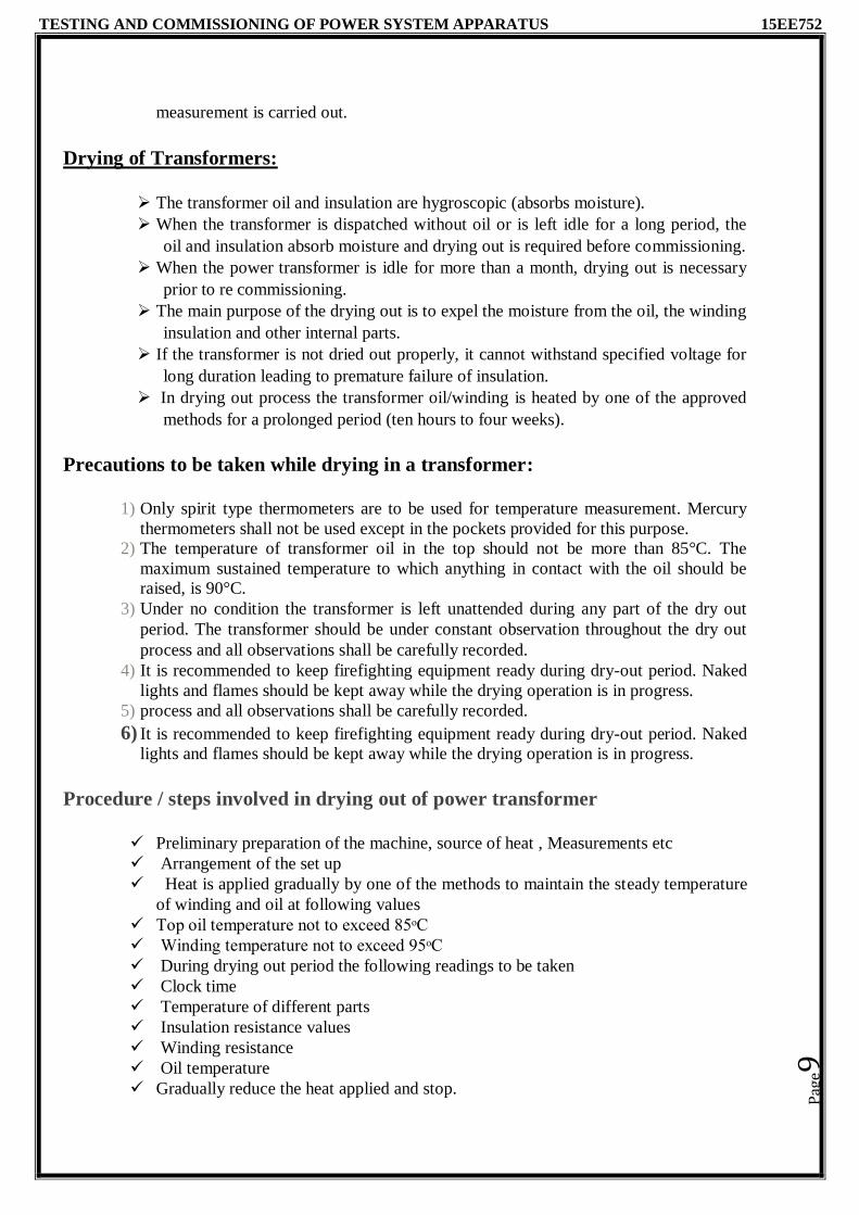
1. Polarity testing
Polarity means the direction of the induced voltages in the primary and the secondary
winding of the transformer. If the two transformers are connected in parallel, then the polarity
should be known for the proper connection of the transformer. There are two types of polarity one
is Additive, and another is Subtractive.
Each of the terminals of the primary as well as the secondary winding of a transformer is
alternatively positive and negative with respect to each other as shown in the figure below. Let A1
and A2 be the positive and negative terminal respectively of the transformer primary and a1, a2 are
the positive and negative terminal of the secondary side of the transformer. If A1 is connected
to a1 and A2 is connected to a2 that means similar terminals of the transformer are connected, then
the polarity is said to be additive. If A1 is connected to a2 and A2 to a1, that means the opposite
terminals are connected to each other, and thus the voltmeter will read the subtractive polarity.
Connect the circuit as shown in fig and apply the voltage gradually. Now note down the
values of voltmeter V1,V2 andV3. If V3 reads V1 + V2 shows the proper connections and the
connections made permentanly. If V3 reads V1 - V2 shows the improper connection then
connection has to be changed
2. Measurement of winding resistance To calculate the I2R Loss, it is necessary to know the dc resistance of winding This can be done in
two methods - Current Voltage Method and Wheatstone/Kelvin bridge method.
Current Voltage Method
Before measurement the transformer should be kept in OFF condition without excitation at least
for 3 to 4 hours. During this the winding temperature becomes equal to oil temperature.
Measurement is done once the DC current reaches steady state. The DC voltage applied gradually
to windings. The readings of the current and voltage have been taken and resistance is calculated.

TESTING AND COMMISSIONING OF POWER SYSTEM APPARATUS 15EE752
Pag
e14
By wheat stone bridge/ Kelvin bridge
This test is conducted at stable temperature .The winding is connected across unknown
resistanceQA1 terminal of the bridge The resistance is determined
The resistance per winding is calculated by
Resistance per winding = 1.5 × Measured value
Winding Resistance at standard temperature of 75oC is calculated by
where R0 = Winding resistance at temperature T0.
T0 = Ambient temperature
R1 =Winding resistance at temperature T1
T1= Standard temperature say 75oC
3. Ratio test This test can be done using calibrated voltmeter .But it is preferable to do it by ratio-
testing apparatus called RATIOMETER. This consists of portable transformer with fixed
primary and secondary winding have large number of taps connected to a two selector switches,
one course and the other is fine, so that any desired could be obtained for direct reading.
The HV side of the transformer under test is connected to a low voltage mains supply
say 400 or 220 V and the induced voltage in the secondary is compared with the voltage output
of Ratiometer, after ensuring the two voltages are in opposition. Accurate readings are obtained
by an ammeter connected between the two windings.

TESTING AND COMMISSIONING OF POWER SYSTEM APPARATUS 15EE752
Pag
e15
4. Insulation resistance test
The insulation resistance is measured between two parts separated by insulation. Insulation resistance of electrical equipment refers to the resistance between conducting part and
earth. It is expressed in mega ohms. Insulation resistance is measured by megger which consists
of a hand driven generator. Meggers are available for dc voltages of 500V, 1000V and
2500V.One of the terminals of megger is connected to conducting part. Other terminal is
connected to the earthed frame as shown in fig. The generator is hand driven and the reading is
directly obtained on the scale graduated from zero to infinity in mega ohms.
when dc voltage is applied, initially the insulation draws capacitive charging current (Ic) in addition to leakage current (IL). Initial megger reading is given by
I0R0 =
I0R0 =
where Ic --- is the charging current and Il --- is the leakage current
After sometime the charging current reduces to zero and only leakage current is present.
I0R0 =
Polarization Index: Polarization index gives the true idea about the quality of insulation and
also the extent of dryness. It depends upon the temperature at which insulation resistance is
measured. Polarization index is the ratio of megger value taken for 60 sec to the megger value taken
for 15sec.
˃1

TESTING AND COMMISSIONING OF POWER SYSTEM APPARATUS 15EE752
Pag
e16
5. MEASUREMENT OF IMPEDENCE VOLTAGE AND LOAD LOSS:
(short circuit test) The voltage to be applied to transformer to circulate rated current in short
circuited secondary is called Leakage impedance voltage or Impedance voltage .The load loss
is sum of IR2 losses in winding and stray losses due to eddy currents in conductors clamps and
tank. The stray losses vary with frequency. The load loss and impedance voltage are guaranteed at
75' C ,but are measured at ambient temperature
The test is carried out by short circuiting ,usually the LV winding and by supplying
the impedance voltage to HV winding .The measured power will also include small core loss.
Load loss and impedance voltage can be corrected for MVA as follows
Computed loss at rated current = Measured loss at test current * Rated current Test current
For calculating the load loss and impedance at different tap positions ,recording should be very
quick and also the interval between the measurements at different taps should be sufficient to
avoid errors due to momentary temperature rise Three watt meters are instead of two watt meters
to avoid large wattmeter multiplier constant. The power factor during load loss should be less
than 0.1 and wattcmeters suitable for such low power should be used.
6. NO LOAD CURRENT AND NO LAOD LOSSES No load current is current drawn by the transformer when there is no load .
Usually no-load current is less than 4% of full load current. Hence I2R losses are negligible
.However only iron losses (hysteresis and eddy current losses) are present in no-load condition
.No load test is performed at normal voltage and frequency with HV winding open circuited. The
LV winding is supplied with normal voltage. the input power measured will give no-load loss.
The no-load current and losses are useful in evaluating the efficiency of transformer

TESTING AND COMMISSIONING OF POWER SYSTEM APPARATUS 15EE752
Pag
e17
TYPE TESTS
1.Temperature Rise Test
The temperature rise test is one of the type tests which confirms the design for
temperature rise. The is called as Heat run test . The test simulates the conditions of continuous
rated load and occurrence of temperature rise
For standard tank, the dissipation constant is known. in such case it is necessary to
measure only transformer losses and to calculate the temperature rise of the coil and winding on
continuous loading .For non-standard tank, it is necessary to carry our temperature rise on the
transformer and different methods to obtain the temperature rise are as follows
1. Short circuit test
2. Back to Back test
3.Delta/Delta test
4. Open circuit test
Short circuit test In this method One winding is short circuited and the Voltage applied to the other
equal to Full load losses of the transformer. The Measurement of temperature is done using
Thermocouples placed in the transformer.
Delta/Delta test In this method the Full rated voltage is applied to one winding Which accounts for
full load iron losses. By external source full load current is circulated in another winding,Which
accounts for full load copper losses. As current circulated in winding the temperature in the
winding rises Record the temperature of the winding for every 15mins till it reaches steady
value.Time take to reach the final temperature is Thermal time constant.
Significance of temperature rise test
Gives temperature rise during the load
Conditions for rated load
It gives full load copper and iron losses
Idea about cooling

TESTING AND COMMISSIONING OF POWER SYSTEM APPARATUS 15EE752
Pag
e18
2.IMPULSE VOLTAGE TEST
Lightning is probably the most common cause of flashover on overhead transmission lines. The
terminal equipments of high voltage transmission lines experience the lightning pulse in service.
Hence impulse voltage test is done for transformer to check the withstand capacity.
Test set up for impulse testing of power transformer
The impulse voltage is produced by discharge of a capacitor or number of capacitors
into a wave generating network and so produced impulse voltage is applied across the object
under test. For HV impulse test a multi stage impulse generator which is the modified marx’s
original circuit is used. This consists of number of capacitors initially charged in parallel and
discharged in series by the sequential firing of interstage gaps. Fig shows simple single stage
impulse generator and test setup
This test is necessary for all indoor and outdoor transformer. Standard impulse wave of
specified amplitude is applied twice in succession. If there is no flash over and puncture of the
insulator, then the transformer is considered to have passed the test , on other hand ,if there is
puncture occurs ,is considered to have failed the test. During the test one wave should be applied
with reversal of polarity. The peak value and wave shape of the test voltage is recorded by means
of storage oscilloscope

TESTING AND COMMISSIONING OF POWER SYSTEM APPARATUS 15EE752
Pag
e19
3.Power frequency withstand test
It is a routine test conducted at specified test voltage .The test voltage is depending
upon the type of transformer . The test Voltage is derived from AC generator driven by motor
.The High voltage Transformers are cascaded to get High voltage. The test voltage is gradually
raised and kept applied for 1 minute to check the withstand capacity. This test is performed to
check the flash over or breakdown
4. Sudden short circuit withstand test
This is a type test conducted in short circuit testing station to check the withstand
capacity for external short circuit. The power transformer must be designed to withstand the
mechanical and thermal stress caused by external short circuit. When the short-circuit current
flows through the winding, the winding is subjected to radial electromagnetic force. These forces
produce stresses on outer windings as well as inner winding which may be tending to collapse the
winding. Therefore the winding should not get deform when short circuit current is circulated .In
order to check this the secondary of the Transformer is shorted and specified voltage is applied for
2 seconds to observe the deforming of windings.
Transformer Accessories, Fitments and Safety devices
Transformer accessories plays an important role in ensuring proper functioning of the
main equipment. Some accessories provide safety during fault condition
1. Cooling
The oil act as an insulating medium and cooling medium. Heat generated is removed by the
oil and transferred to atmospheric air or water
The effective cooling ensures longer life due less thermal degradation
Methods of cooling of Transformer
Transformers can be divided in two types as (i) dry type transformers and (ii) oil
immersed transformers. Different cooling methods of transformers are -
For dry type transformers
Air Natural (AN)
Air Blast
For oil immersed transformers
Oil Natural Air Natural (ONAN)
Oil Natural Air Forced (ONAF)
Oil Forced Air Forced (OFAF)
Oil Forced Water Forced (OFWF)
Air Natural or Self Air Cooled Transformer
This method of transformer cooling is generally used in small transformers (upto 3 MVA). In
this method the transformer is allowed to cool by natural air flow surrounding it.

TESTING AND COMMISSIONING OF POWER SYSTEM APPARATUS 15EE752
Pag
e20
Air Blast
For transformers rated more than 3 MVA, cooling by natural air method is
inadequate. In this method, air is forced on the core and windings with the help of fans or blowers.
The air supply must be filtered to prevent the accumulation of dust particles in ventilation ducts. This
method can be used for transformers upto 15 MVA.
Oil Natural Air Natural (ONAN)
This method is used for oil immersed transformers. In this method, the heat generated
in the core and winding is transferred to the oil. According to the principle of convection, the
heated oil flows in the upward direction and then in the radiator. The vacant place is filled up by
cooled oil from the radiator. The heat from the oil will dissipate in the atmosphere due to the
natural air flow around the transformer. In this way, the oil in transformer keeps circulating due to
natural convection and dissipating heat in atmosphere due to natural conduction. This method can
be used for transformers upto about 30 MVA
Oil Natural Air Forced (ONAF)
The heat dissipation can be improved further by applying forced air on the
dissipating surface. Forced air provides faster heat dissipation than natural air flow. In this method,
fans are mounted near the radiator and may be provided with an automatic starting arrangement,
which turns on when temperature increases beyond certain value. This transformer cooling method
is generally used for large transformers upto about 60 MVA.

TESTING AND COMMISSIONING OF POWER SYSTEM APPARATUS 15EE752
Pag
e21
Oil Forced Air Forced (OFAF)
In this method, oil is circulated with the help of a pump. The oil circulation is forced
through the heat exchangers. Then compressed air is forced to flow on the heat exchanger with the
help of fans. The heat exchangers may be mounted separately from the transformer tank and
connected through pipes at top and bottom as shown in the figure. This type of cooling is provided
for higher rating transformers at substations or power stations.
Oil Forced Water Forced (OFWF)
This method is similar to OFAF method, but here forced water flow is used to dissipate hear
from the heat exchangers. The oil is forced to flow through the heat exchanger with the help
of a pump, where the heat is dissipated in the water which is also forced to flow. The heated
water is taken away to cool in separate coolers. This type of cooling is used in very large
transformers having rating of several hundred MVA.

TESTING AND COMMISSIONING OF POWER SYSTEM APPARATUS 15EE752
Pag
e22
2.Buchholz Relay
Buchholz relay is used for the protection of oil filled transformer from incipient
faults below oil level. This relay is installed between the transformer tank and conservator.
Whenever the fault occurs due to low oil level the relay gives the alarm. The arc due to the fault
causes the decomposition of oil. The product of decomposition contains more than 70% of
hydrogen gas, which being light, rises upwards and tries go in the conservator. The buchholz relay
is fitted in the leading to conservator . The gas get collected in the upper portion of relay, there by
the oil level in the relay drop down .The float, floating in the oil levelin the relay tilts down with
the lowering oil level. While doing so the mercury switch , attached to the float is closed and
mercury switch closes the alarm circuit. Thereby the operators know about there is some fault in
transformer and is disconnected as soon as possible. The gas sample is tested and testing gives
idea regarding the type of fault. The schematic diagram is as shown in the fig
3.TAP CHANGERS
The voltage variation is a normal phenomenon ,because of rapid growth of electrical load and
distribution network. It is necessary to maintain system voltage within the specified limit for the
better health of electrical equipment .The system voltage maybe adjusted by changing the tapping
on the power transformer. The variation in voltage may be brought in either by step or step less
control .But the practice proved that voltage variation is handled effectively in steps without
creating objectionable disturbance on the system. This variation is generally achieved by means of
tappings on the power transformer because of the smaller currents to be dealt with , are normally
located on the higher voltage winding

TESTING AND COMMISSIONING OF POWER SYSTEM APPARATUS 15EE752
Pag
e23
Off circuit tap changer: The economic method of changing the turns ratio of a
transformer is the use of off-circuit tap changer. As the name suggest ,it is necessary
to de-energize the transformer before changing the tap. A mechanical lock is provided
to prevent unauthorized operatin and inadvertent operation. The transformer are
normally provided with off-circuit taps with +2.5 percent and +5 percent on hv side.
The station transformers are preferably provided with OLTC with +10% in steps of
1.25 percent on hv side
On Load Tap Changer(OLTC); OLTC are employed to change turns ratio of
transformer to regulate to regulate system voltage while the transformer is delivering
norml load. With the inception of OLTC , the operating efficiency has considerably
improved. All forms of OLTC circuit posses an impedance, which is introduced to
avoid short circuiting of tapping section during tap changer operation. The OLTC can
in general, be classified as resistor or rector type. As the motor drive unit is initiated
by a push button or voltage control relay, tap selector changes tap. the diverter switch
diverts the current .The tap changers function without interruption in load current.
4. Flow or oil level indicator: it is fitted in oil circulation system which indicates the Flow
rate. it is used for control purpose in combination with float switches for starting and stopping of
oil pumps
5.Pressure relief valve: It is fitted on the tank to act as an exit for gasses formed of oil. A up of
gaseous pressure .If this pressure is not relieves within few milliseconds ,the transformer tank gets
ruptured ,spilling oil over wide area..
6.Sudden pressure relay: (Rate of rise of pressure relay): The rate of rise of pressure relay
responds to sudden rise of pressure due to internal arcing. The relay is fitted on the tank
7. Conservator: It is a large cylinder connected by pipe to the transformer. The oil is filled upto
certain level in the conservator
8.Breather: one end of breather is connected to air cushion in conservation and the other end is
towards the external air
9.Oil temperature indicators: the thermocouple is placed in the pocker provided with the
tank near hot oil
10. Winding temperature indicator (Hot spot indicator)with alarm and tripping
contacts: Thermocouples are placed in the tank near hot oil. The indicator is provided with alarm
and tripping contacts

TESTING AND COMMISSIONING OF POWER SYSTEM APPARATUS 15EE752
Pag
e24
MAINTENANCE OF POWER TRANSFORMER
It is essential to have periodic preventive maintenance of power transformer by
trained person with maintenance facilities. The transformer needs regular maintenance for
satisfactory service. The transformer maintenance includes
1. Routine daily inspections a. Check tank and radiators for unusual noise, oil and water leaks b. Check oil level in conservator c. Check oil level in main tank bushings
d. Check whether cooling water in flowing, whether oil circulation
pump is operating whenever necessary, fans start when necessary e. Check relay panel temperature indicators and confirm normal condition f. Check position of tap changer g. See that oil control/alarm / power/ Supply circuit switches are closed and
fuses in the circuit are well placed 2. Routine monthly inspections
a. Check oil level in main tank , oil filled bushing, etc. if the oil level has
fallen down below specified level for a given temperature the cause of
leakage should be determined b. Check and record oil temperature c. Check bushing surface for signs of chipping dirt, oil, etc. d. Check terminal connections, earthing connections for tightness e. Other checks mentioned in the daily checks
3. Routine annual inspections a. Check water flow indicators and relays for proper operations b. Check foundation for cracking and settling c. Clean dirt and oil from radiating surfaces d. Check external supply and drain piping for leaks e. Clean and test water tubes similar to cooling coil, check for oil and water leaks f. Tighten all buss and ground connection g. Inspect contacts and clean if reachable on internal inspection h. Drain oil from contact compartment, clean and refinish contact surfaces i. Check insulation resistance between each winding and between winding
and ground j. Check the dielectric strength of the insulating oil

Module-2 Synchronous Machines
a. Specifications: As per BIS standards.
b. Installation: Physical inspection, foundation details, alignments, excitation systems,
cooling and control Gear, drying out.
c. Commissioning Tests: Insulation, Resistance measurement of armature & field
windings, waveform & Telephone interference tests, line charging capacitance
d. Performance tests: Various tests to estimate the performance of generator
operations slip test, Maximum lagging current, maximum reluctance power tests,
sudden short circuit tests, transient & sub
Transient parameters, measurements of sequence impedances, capacitive reactance, and
separation of losses, Temperature rise test, and retardation tests
Introduction: Synchronous generators and Synchronous Motors are called Synchronous
Machine
Synchronous generator is the major component of power system.
Based on the source of power generation they are classified a) Turbo Alternator
b) Gas turbo -generators c) Industrial Synchronous generators
Standard specifications of a Rotating Machines
The important step in selection of Synchronous Machines for specific application is deciding
the ratings considering all affecting parameters.
Voltage Rating: 11KV, 3.3KV,1.1KVetc
Excitation Voltage: 110V-1000V DC
Excitation Current: 10 to 100A
Power Rating: specified in KW
Type of Mounting: The mounting is to be specified like vertical mounting,
Horizontal mounting etc.
Rated Current and rated frequency with variation
Class of insulation: The class of insulation used for winding is to be given i. e class A,
E, B, F and H
Ambient temperature
Type of construction and bearing arrangements
Cooling system
Method of starting and drive details
Performance requirements with respect to efficiency and related parameter

INSTALLATION OF SYNCHRONOUS MACHINES
Various steps in installation of an alternator
Installation of bed plate and the leveling of bed plate
Installation of the bearing pedestals and leveling of the bearing pedestals
Checks on stator and rotor
Assembly of the rotor onto the shaft
Installation of the stator
Installing the rotor in the stator
Checking of the air gap between stator and rotor
Preparation of shaft couplings
Mounting of shaft couplings on shaft
Preparation of shafts and alignment of shafts.
Installation of cooling systems
Drying out
Testing
Commissioning
Each of the above activities should be carried out by technically skilled staff. The instruction manual supplied by the manufacturer should be referred in practice. Shaft alignment should be, perfect to get trouble free mechanical performance of the
generator with the driven equipment. The rating plate is of definite dimensions as per IS Code. The ratings are etched or engraved and is fixed to the machine in a clearly visible position.
1. Physical Inspection: The synchronous generator received at site must be stored in a
safe place. before storing ,the machine should pass an acceptance procedure intended to
check it for missing or damaged parts. Take the necessary measures for excluding the
violation of installation terms. Checking should be done in presence of representative of
the supplier. Large capacity synchronous generators are delivered in a disassembled
condition.
2. Foundation : Large alternators require strong foundation depending on the type of
mounting i.e. Horizontal or Vertical . Alternators in generating stations are usually vertically
mounted. Foundations should be separated from columns and supporting structures of the
building so as to prevent the transfer of vibrations of machine to the building. Basic
dimensions of the foundations are specified by the manufacture in the drawing. The
foundation must be provided with holes to receive anchor bolts shall be fixed in the concrete.
The alternator is installed in a strong structure constructed for this purpose only
Pag
e2

Excitation system
The rotor of a synchronous machine needs dc current for excitation. The field current is
supplied and controlled by the excitation system. An excitation system includes all the
equipment required for supply of field current and voltage regulator system. Excitation
response is the rate of change of exciter voltage and is expressed in terms of volts per second.
The maximum voltage that may be attained by an exciter under specified condition of load is termed as excitation ceiling voltage. The function of the excitation system is to
supply and regulate field current.
Brushless (static) excitation system:
a- Permanent magnet alternator (Rotating field, stationary armature)
b - Magnetic amplifier
c - AC exciter (Rotating armature, stationary field) d - Silicon diode rectifier (Revolving with
rotor)
d—silicon diode rectifier.
e - Main generator field or rotor
f - Feed back of generator voltage for control and regulation
The silicon diode rectifier is mounted on the same shaft to excite the field of the main
generator directly. An ac exciter is used to feed power to the revolving rectifier. The field of the ac exciter is fed by a magnetic amplifier that controls and regulates the output
voltage of the main generator. The excitation power for the magnetic amplifier is obtained
from a small permanent magnet alternator which is also driven from the main shaft. The
voltage and frequency of ac exciter are selected so as to optimize the performance and design of the overall system
Automatic Voltage Regulators and Excitation System
Performance of a synchronous generator has interface with the complete generator- turbine unit, bus bar connected other units and the grid. A synchronous generator has a 3-phase distributed AC Armature winding on stator and DC excitation main field winding on the rotor. The rotor is driven at synchronous speed by prime mover. The main excitation field winding on rotor of the alternator is supplied DC Voltage by the excitation system. The main alternator excitation field current is increased or decreased by changing the exciter voltage by Automatic voltage regulator(AVR) and its feedback control system. Rotating magnetic field of Dc excitation field of rotor induces 3 phase Ac EMF in stator armature winding. Flow of stator armature current Ia produces induced
Pag
e3

revolving magnetic field in the air-gap, revolving At synchronous speed and locked with the rotor magnetic field. The angle between the stator field and rotor field is the load angle which increases with load and undergoes oscillation during disturbances. The main exciter provides DC field Voltage and current to the rotor field winding of the generator. The exciter terminal voltage decides the excitation current. The AVR controls exciter terminal voltage and alternator excitation rotor field current to regulate generator terminal voltage. The pilot exciter feeds power to the field winding of main exciter.
The AVR in the excitation system plays a very vital role Voltage control, controlling reactive power supply, emf, Voltage and power factor of generator, and also maintaining power system dynamic stability, and in protection of alternators by imposing several limits on generators variables.
The Functions of an AVR 1. Regulation of terminal voltage automatically: To regulate the terminal voltage within specified limits of the generator automatically under steady state operating condition of varying load/pf. This is done by controlling field current by means of a feedback system involving voltage transformer and AVR. 2. To facilitate reactive power load sharing with other generators operating in parallel 3. To regulate the voltage and load angle under abnormal conditions and transient disturbing such as faults, power swings, sudden switching in of large loads, etc 4. To damp swing and electromagnetic oscillations in load angle under abnormal conditions and transient/dynamic disturbing conditions rotor oscillations of synchronous generators and ensure stable operation. 5. To ensure protection of generators and excitation system by giving tripping command under appropriate abnormal conditions of variables. 6. Limiting Features: To inhibit the tripping of the generators unit by protection system under permissible swings in active power and reactive power. AVR operates in close liaison with the generator protection system and raises the operating limits for ensuring generator service during disturbances.
Pag
e4
Cooling Methods
The methods employed for cooling of synchronous machine are
Open circuit cooling: A method of cooling in Which the coolant is drawn
from the medium surrounding the machine, passes through the machine and then returns to the surrounding medium.
The methods used in open circuit cooling
Enclosed ventilated
Weather protected
Output water/heat exchanger
Closed circuit cooling: The primary coolant is circulated in a closed circuit through the machine and if necessary, through heat exchanges. Heat is transferred to the secondary coolant.
The methods used in closed circuit cooling
Totally enclosed
Totally enclosed fan cooled
Totally enclosed fan/tube cooled
Totally enclosed separate air cooled
Closed air circuit air-cooled integral fan
Closed air circuit air-cooled separately driven-fan
Further the cooling system may be
Standby or emergency cooling system
Dependent circulating circuit components &Independent circulating circuit components & Integral circulating circuit components
Machine mounted circulating circuit components v' Separately mounted
circulating components
Hydrogen cooling
Water cooling
Hydrogen cooling of turbo - generators:
The thermal conductivity of hydrogen is about 7 times that of air. The density of hydrogen is 0.07 times that of air. The specific heat of hydrogen is 14 times that of
air. Hence hydrogen gas is preferred to air as a coolant in Large turbo generators of
capacity 60 MW and above. It reduces noise and improves heat transfer. The
hydrogen cooling is direct cooling i.e. the cooling medium is in direct contact with
conductors. The hydrogen gas is passed through the rectangular tubular cross section rotor conductors. The stator conductors are hollow and hydrogen gas from a separate
circuit is circulated through the stator conductors. The pressure of the gas is of the
order of 1.5 Kgjm2 and flow rate is about 15 m3 jess. Hydrogen blowers are required
to circulate hydrogen gas through direct cooled machine.
Pag
e5

TYPES OF ENCLOSURES
1. Open Pedestal: In this the stator and rotor ends are open to the outside ambient temperature, the rotor being supported on pedestal bearings mounted on the bedplate.
2. Open End Bracket : In this the bearings forms part of the end shields which are fixed to
the stator housing . The air is in comparatively free contact with stator and rotor.
3. Protected or End-Cover type with guarded Openings: The protector may be Screen or
fine mesh covers.
4. Drip,Splash or hose proof: This is complete protected Machine with openings in the end
shield for Cooling.
5. Pipe or Duct Cooled: With the end covers Closed except for flanged openings for
connection to cooling pipes.
6. Totally Enclosed: In this type , the air will not be in contact with the ambient air, The
machine is totally air tight. Total enclosure may be associated with an internal rotor fan, an
external fan.
7. Flame proof or Explosion proof: This Motor is used in hazardous location such as mines,
chemical Industries.
Duty
The duty requirements shall explicitly be given by the purchasers as accurate as possible. The
Duty requirement may be declared numerically or with the aid of time sequence graphs. The duty
declaration for an electric motor is very important as the electric motors have the time rate of
temperature rise.
Classes of Duty: S1 - continuous Duty: The motor is running long enough
S2 - short time Duty: Time of operation is very low
S3 - Intermittent periodic Duty: The motor operates for some time and then there is
rest period
S4 - intermittent periodic Duty with starting
S5 - continuous duty with intermittent periodic loading
S6 - continuous duty with starting & electric braking
S7 - continuous duty with periodic speed change
Pag
e6

0 60
Drying of Windings
The Insulation of Rotating machine is Hygroscopic(absorbs moisture) in nature. The
Moisture reduces the insulation resistance. It is essential to remove the moisture before
commissioning of the machine. The high resistance of Insulation gives the degree of dryness
of the insulation. The moisture is evaporated from winding due to thermal diffusion. The
moisture gradient depends on temperature gradient within wet insulation. The Desired
temperature is obtained by heating the winding. The insulation is measured by means of DC
Mega ohm meter(Megger). The Phase to Phase and Phase to earth insulation resistance
I0R60(Mega ohms). At the Working temperature of the machine should not be lower than the
Value found from the Equation.
I R = 𝑉𝑟𝑎𝑡𝑒𝑑
1000+0.01𝑃
Where Vrated -- Rated voltage across the machine in Volts
P -- Rated output of the machine in KW.
Polarization Index: Is the ratio of insulation resistance of 60sec megger readings to the
insulation resistance of 15sec megger readings.
𝐼𝑜𝑅60 PI =
𝐼𝑜𝑅15
Procedure for Drying out of Synchronous Machine
The machine is connected to low voltage source. The input voltage, current, power, the
temperature of winding, temperature of body, temperature of hot air is periodically
recorded. The end covers of the machine are removed. The machine body is covered with
tarpaulin. The increase and decrease of the temperature should be gradual. The rotor is
blocked. The current through the stator winding not to exceed 50% of the rated current
P
age7

The drying out procedure has three distinct phases.
In the beginning the insulation resistance decreases indicating that the moisture is
getting released within the insulation.
After few hours the insulation resistance reaches the steady state value indicating the
moisture content is distributed within the winding.
In the last stage the insulation resistance start increasing indicating the moisture is
expelled out. The drying out procedure is stopped when the desired value of hot
insulation resistance and polarization index are achieved for each winding .
Testing of Synchronous Machines
1. Tests on synchronous generators:
Insulation resistance test on stator winding
Measurement of dc resistance of armature and field windings
Dielectric test on stator windings by AC voltage for 1 min.
Dielectric test with DC voltage
Measurement of dc resistance of field discharge resistor
Testing of insulation of the field discharge resistor with respect to frame.
Testing of insulation resistance and dielectric withstand of field insulation.
Measurement of vibrations.
Noise measurement
Measurement of air gaps between stator and rotor
Open circuit characteristic the measuring terminal voltage for various field currents at no load and rated speed
Short circuit characteristics by changing field current and measuring short circuit armature current
Sudden 3 phase circuit test to record the oscillograms of short circuit current at three phase
Testing on voltage regulator excitation systems
Pag
e8

2. Tests on synchronous motors:
Measurement of dc resistance of armature & field windings
Dielectric tests on armature and field windings
Mechanical balancing test
Current balance on no load
Direction of rotation
Phase sequence test
over speed test
Harmonic analysis
Telephone interference ./ Short circuit test
Reactance and time constants ./ Speed torque characteristics Efficiency calculations
Bearing insulation test
1. INSULATION RESISTANCE TEST
The insulation resistance of stator winding to earthed frame, rotor winding to earthed frame, phase to phase winding pedestal and bearing insulation resistance is
measured using megger. The megger readings for 15 seconds and 60 seconds are
taken to find the polarization index.(for diagram and explanation refer
Transformer 1&2 unit notes)
2. MEASUREMENT OF DC RESISTANCE OF WINDINGS
The dc resistance of armature windings, field windings and field discharge resistance are measured using the following methods.
a) Voltmeter ammeter method: In which voltage applied across the winding and
current through the winding are noted at the specified temperature. Then the
resistance is calculated. This is suitable for field resistance measurement. Built in bridges via Wheatstone bridge and Kelvin's double bridge are used to measure field
resistance & armature resistance respectively. As resistance is sensitive to
temperature, temperature is also recorded and three to five readings are taken.
b) Reference Field Resistance: The resistance is normally measured at standstill
condition by allowing rotor being exposed to sufficient time. This is for entire rotor to reach the ambient temperature. This reference resistance helps in determining the
field temperature during running by the method of variation of resistance. When
reference resistance is measured, the current circulation through the field coil shall
be low , so as not to cause change in temperature. Both the resistance and temperature can be determined more accurately by conducting the test when the
generator isrunning near normal speed.
Pag
e9

3. OPEN CIRCUIT TEST (NO LOAD SATURATION TEST)
The open circuit characteristics of a synchronous machine is the curve showing the
relationship between armature terminal voltage and field excitation. The prime
mover is run at rated speed. The excitation is varied in steps and corresponding no
load voltage is recorded. The characteristic curve may be plotted in per unit where
unit voltage and unit excitation corresponding to rated voltage and excitation current
on the air gap Line. The open circuit characteristics represent the relation between
the space fundamental component of the air gap flux and the miff on the magnetic
circuit when the field winding constitutes the only source. During no Load test the no
Load Losses of the machine can be obtained. The test circuit for No load test and NO
load characteristics are shown.
4. SUSTAINED THREE PHASE SHORT CIRCUIT TEST
In this test, the synchronous generator terminals are shorted through ammeters as
shown in fig. and the field current is gradually increased till the ammeter current
reaches a maximum safe value (about 1.5 times rated current). The relation between
field current and short circuit current is drawn and is known as short circuit
characteristics. In sustained Short circuit test, the values of field current and armature
current refer to the steady state values and measured using indicating meters.
The sustained three phase short circuit test is also conducted by a retardation test on
the machine. The machine under test is driven by an electric motor at rated speed and
is excited to get the short circuit current in the armature. The machine under test is
retarded by putting off the supply to driving machine. The armature current in each
phase and the corresponding field current are noted. If the machine has retardation
above 4 percent of its rated speed per second, excitation from separate source is used
to get stable excitation during the test
Pag
e10

Pag
e11
5. SHORT CIRCUIT RATION (SCR) OF SYNCHRONOUS MACHINE
The Short circuit ration of synchronous machine is defined as the ratio of field current Ifoc required to obtain rated open circuit voltage to the field current Ifsc required for obtaining rated sustained short circuit current when running at rated speed .
SCR = 𝐼𝑓𝑜
= K 𝐼𝑓𝑠𝑐
The SCR is obtained from the data of the No load test and sustained short circuit test
conducted on a machine as shown in fig. The impedance in the steady state condition is is
known as the synchronous impedance and defined as the ratio of field current at rated
armature current on sustained symmetrical short circuit to the field current at normal open
circuit voltage on the air gap line.

SUDDEN 3- SHORT CIRCUIT TEST
When an alternator is subjected to sudden short circuit, the current in all the three Phases increases suddenly to a high value (10 to 8 times full Load current) during the First quarter cycle. The flux crossing the air gap is Large during first couple of cycles. The reactance during this period is Least and the short circuit current is high. This Reactance offered during sub transient period is called as sub transient reactance Xd΄΄. The First few cycles are covered under sub transient state. After few cycles the decrement in rms value of short circuit current is Less rapid than that during the first few cycles. This State is called as Transient state and the reactance offered during this period is called as transient reactance Xd΄. The circuit breaker contacts open during this period. Finally the transient dies out and the current reaches a steady sinusoidal state called the steady state and the reactance offered during this state is called as steady state reactance Xd. Since the short circuit current lag the voltage by 90°, the reactance involved is direct axis reactance.
The sudden 3-phase short circuit test is conducted at rated speed and at desired no load voltage.
The 3 phases are shorted suddenly.
To measure short circuit current storage oscilloscope with proper probe multiplier is used.
The terminal voltages of machine and excitation current and winding temperature are measured just before the short circuit.
To obtain quantities corresponding to the unsaturated state of the machine, the test is performed at several armature voltages of 0.1 and 0.3PU of rated value.
To get quantities corresponding to the saturated state of the machine, the test is
performed with rated at the terminals of the machine before applying the short circuit
to the armature winding.
To determine the machine quantities, oscillogram of the armature current in the excitation is taken.
The short circuit is initiated by closing the circuit breaker
Fig A shows the test set up and fig B shows the oscillogram current
Pag
e12

The currents and reactance are given by the following expressions
I = 𝑶𝑨
=𝑬𝒂
; X -- Steady state reactance = 𝐸𝑎
√𝟐 𝑿𝒅 d 𝐼
I' = 𝑶𝑩
= 𝑬
; X'
-- Transient state reactance = 𝐸𝑎
√𝟐 𝑿𝒅′ d
𝐼′
I'' = 𝑶𝑪
= 𝑬𝒂 ; X '' -- Sub transientstate reactance = 𝐸𝑎
√𝟐 𝑿𝒅′′ d 𝐼′′
Where OA,OB,OC are intercepts of X-axis as shown in fig
Ea - rms value of positive sequence emf, per phase , induced by the generator
I - Steady state short circuit current, rms value
I' - Transient short circuit current, rms value
I'' - Sub transient short circuit current , rms value
6. NEGATIVE PHASE SEQUENCE TEST
The test is conducted when reduced symmetrical voltage (0.02-0.2) up is applied to
the machine driven at rated speed, connected to an external source of supply with
negative phase sequence i.e. operating as an electromagnetic brake with the slip
equal to 2. The excitation winding is short circuited. If the residual voltage of the
machine under test exceeds 0.30 times of the supply voltage, the rotor should be demagnetized before testing the machine. The voltage and current in all the three
phases and power are noted.
7. SLIP TEST AND CALCULATION OF Xq & Xd
During the slip test, subnormal symmetrical three phase voltage of magnitude 10 to
20% of the rated voltage is applied to the armature terminals of the machine. The
field of the alternator is either open circuited or short circuited. The prime mover is
run at slightly less than synchronous speed to get a slip of 0.01. Armature current and
voltages are measured using indicating instruments or recorded by using oscilloscope. The ammeter & volt meter readings will indicate two values which are
to be taken as minimum and maximum quantities respectively. To find out Xq and
Xd
Xq = 𝑉𝑚𝑖𝑛
√3 𝐼𝑚𝑎𝑥 ohm
Xd = 𝑉𝑚𝑎
ohm √3 𝐼𝑚𝑖𝑛
Pag
e13

If Imax do not coincide with Vmin, use in calculations Imax as a base and its corresponding voltage.
If during the test, the residual voltage of the machine is in the limits of 0.1-0.3 of the
supply test voltage
8. POWER FREQUENCY VOLTAGE WITHSTAND TEST
This test is conducted on 3 phase ac windings of an ac generator with the specified
values of power frequency test voltage. The test voltage of (2V+l) KV is applied for
specified time (1 minute) between windings and earthed frame. The machine parts should not exhibit flash over, to consider it to have passed the test.
9. VIBRATION TEST
The vibration test is carried out on the complete machine after assembly and
balancing of the machine. A set of three orthogonal accelerometers are fixed on each
bearing. The vibrations are measured in two directions normal to the shaft. For vibration test the machine is run at no load without coupling to any machine.
Noise in Motors The noise of a rotating machine is generated by a cooling air from its fan as it passed through or over the machine. Some noise reduction is possible by substituting unidirectional trailing bladed fans by the normal radial blades Further reduction is achieved by inlet and outlet silencers or the adoption of closed ventilation circuit of cooling air. The noise is also caused by magnetic effects and dependent on the stator and rotor slots. It c a large vibration of air-gap flux density. This may produce a penetrating note at approximately slot frequency (e.g. 0.5 – 1.5kHz). The amplitude of stator permeance variation may be the cause, but the amplitude also depends on higher order rotor m.m.f. space harmonics. The frequency of the noise is twice the product of the supply frequency with that integer nearest to the number of slot per pole.
Noise Reduction : Noise is caused by 1. Magnetostriction, 2. Aerodynamics, 3. Bearing noise of rotating shaft
Speed and Power effect: - Totally enclosed machine give least sound. Open ventilated machine give
maximum sound. - Ventilation noise predominates in 2-pole machines - Magnetic noise is predominating in machines with more number of poles - When bearing, noise become audible, the other two become less significant
Methods to reduce the noise for DC Machine
- Reduced magnetic loading. - Increase number of armature slots – Skewing of slots. - Continuously graded main pole gap (more at pole end and least at pole centre) - Increase in air gap – Brace commutating poles against main poles - 12 pulse thyristor for speed control and not 6-pluse - Semi- enclosed slots or closed slots for compensating windings
an occur in machine with fractional number of open slots per pole, producing a relatively Pag
e14

10. LOW SLIP TEST
During the low slip test, sub normal symmetrical 3phase voltage is applied to the armature
terminals of the machine under test. The voltage should be such that the machine does not
pull in. The excitation winding should be open circuited and rotor should be driven by a
prime mover at a slip less than 0.01pu. There by the current induced by the damper winding
during synchronous operation will have negligible influence on the measurements. During
switching on and off of the supply, the excitation winding should be closed to avoid possible
damage. The armature current and voltage and slip ring voltage and Slip are measured by
indicating instruments or recorded by Oscillograph If the residual voltage measured before
the test is larger than 0.3 of the supply test voltage, the rotor should be demagnetized.
To determined Xq from the low slip test, armature current and voltage are measured to
maximum excitation winding voltage (U) and Xq is calculated using the formula
Xq = 𝑉𝑚𝑖𝑛
√3 𝐼𝑚𝑎𝑥 ohm
11. Temperature rise test:
Xd = 𝑉𝑚𝑎𝑥
ohm √3 𝐼𝑚𝑖𝑛
The aim of this test is to find out the temperature rise on different parts of the motor while running at rated
conditions. During temperature rise test, the motor should be shielded from currents of air entering from adjacent
pulleys and other machines. A small current of air may cause great discrepancy in results obtained. The duration of temperature rise test depends on the type of rating of the motor. For motors of continuous rating, the test should be
continued till the thermal equilibrium is reached. For motors of short time rating the duration of test corresponds to
the declared short time rating, the test should be continued till the thermal equilibrium is reached. Methods of measuring temp The following methods are approved for determining the temperature of windings and other parts of
motor.
1) Embedded temperature detector method:
Embedded temperature detectors are resistance thermo-meters or thermocouples built in the machine at points which are inaccessible when the m chine is assembled. This method is generally employed for the slot portion of stator windings. At least six detectors to be built in a machine suitably distributed around the circumference.
2) Resistance Method:
This method is generally used for stator whirling’s. Here temperature is determined by the increase in the resistance of the windings. 3) Thermometer method:
In this method, the temperature is determined by thermometers placed at the accessible surface of the rotor.
Pag
e15
ABNORMAL CONDITIONS AND EFFECTS ON SYNCHRONOUS
GENERATOR
1. External faults beyond generator protection:
During external faults with large short circuit current s, severe mechanical stress will
be imposed on the stator windings. If any mechanical defects already exeunt in
winding, these may be further aggravated. The temperature rise is however,
relatively slow and a dangerous temperature level may be obtained after about
10seconds. With asymmetrical faults, severe vibration and overheating of rotor may
occur
2. Thermal overloading
Continued loading may increase the winding temperature to such an extent that the insulation will be damaged and its useful life reduced.
Temperature rise can also be caused by failure of cooling system.
3. Unbalanced loading
Continued unbalanced load cause dangerous heating of the cylindrical rotator in turbo generator
Unbalanced loading on generator can be due to unsymmetrical false in the system or due to the mal operation of circuit breaker near generation station
4. Stator winding faults a. Phase to earth faults: These faults normally occur in the armature slots. The
damage at the point of fault is directly related to the selected neutral earthing
register. Severe damaged may be caused owing to the large time constant of the
field circuit and relatively long time required to completely surplus the field
flux
Phase to phase faults: A phase to earth fault may cause the phase to phase
faults within the slots. It is most likely to be located at the end connection
of the armature winding. This fault causes a severe arcing with high temperatures, melting of copper and risk of fire
5. Field winding faults
The unbalanced loading of generator gives rise to negative sequence
currents which causes negative sequence component of magnetic field. The
negative sequence field rotates in opposite direction of the main field and induced emf in the rotor winding, thus causes rotor heatin
6. Over voltages Surge due to lightening and switching
Surge voltages are caused by direct lightening strokes to the aerial lines in the
HV systems. The amplitude and the duration of the surged on the generator side
dependence on the type of surge arresters used on HV side. This causes the
insulation failure 7. Loss of excitation: Results in loss of synchronism and slightly increased speed.
The machine continues to run at an inductance generator, drawing excitation
current from bus bars the damper winding acts like a squirrel cage. This causes
over heating winding and rotor winding 8. Motoring of generator: When the input to the prime mover stops the generator
draws a power from bars and runs as synchronous motors in the same direction.
Effect depends upon the type of prime mover and the power drawn from buss
bar during motoring 9. Over fluxing of transforms in the generating stations : Causes heating of
core bolts and failure in core bolt insulations Pag
e16

Testing and Commissioning of Power System Apparatus 15EE752
Module 3: Induction Motors
Syllabus: a. Specifications: Power and distribution transformers as per BIS standards. b. Installation: Location, site, selection, foundation details (like bolts size, their number, etc),
code of practice for terminal plates, polarity & phase sequence, oil tanks, drying of windings
and general inspection.
c. Commissioning tests: Following tests as per national & International Standards, volt ratio
test, earth resistance, oil strength, Bucholz& other relays, tap changing gear, fans & pumps,
insulation test, impulse test, polarizing index, load & temperature rise test.
d. Specific Tests: Determination of performance curves like efficiency, regulation etc, and
determination of mechanical stress under normal &abnormal conditions.
Introduction: Induction motors are widely used as industrial drives because of its simplicity,
reliability and low cost.
With the application of thyristor control, induction motor can be used for
variable speed drive.
Induction motor works with better efficiency appreciable over-load capacity and
maintenance required is minimum.
Three phase induction motor are available with various rating from fractional
HP to several thousand HP.
Standard specifications of a Induction Motor
The important step in selection of induction motor for specific application is deciding the
ratings considering all affecting parameters.
Output Rating: The preferred output rating for induction motors upto and
including 110KW are 0.06, 0.09, 0.12, 0.18, 0.25, …….100KW
Type of Mounting:The mounting is to be specified like foot mounting, bed
mounting etc.
Rated voltage and rated frequency with variation
Class of insulation: The class of insulation used for winding is to be given i. e class A,
E, B, F and H
Ambient temperature
Type of construction and bearing arrangements
Type of enclose and cooling system
Method of starting and drive details
Performance requirements with respect to efficiency and related parameters
Pag
e1

Testing and Commissioning of Power System Apparatus 15EE752
Procurement of Induction Motor
When enquiring, and placing an order of induction motor the following particular should be
supplied
Site & operating conditions
Types of enclosure
Reference to this standard i.e IS code number
Types of duty
Method of cooling
Types of construction
Frequency in HZ
No of phase
Mechanical output in KW
Rated voltage & permitted variation
Class of Insulation
Speed in rpm ,at rated voltage
Direction of rotation, looking from driving end
Uni &bidirectional of rotation required
The maximum temperature of air & water used for cooling
Maximum permissible temperature rise
Name Plate details of Induction Motor
Rating plate giving the following details should be supplied with each motor
Reference to standard ex ref IS:325
Induction motor
Name of the manufacture
Manufacture’s number &frame reference
Types of duty
Class of insulation
No of phases
Speed in rpm
Rated o/p in KW
Rated voltage & winding connections
Current in amp rated o/p
Rotor voltage & current
Ambient temperature when above 40*c
Sample Name Plate
Pag
e2

Testing and Commissioning of Power System Apparatus 15EE752
Types of Enclosures
Open ventilated motor
Ventilated motor
Drip proof motor
Water protected motor
Totally enclosed motor
Totally enclosed fan cooled motor
Environment proof motor
Weather proof motor
Hose proof motor
Duty
The duty requirements shall explicitly be given by the purchasers as accurate as possible. The
Duty requirement may be declared numerically or with the aid of time sequence graphs. The duty
declaration for an electric motor is very important as the electric motors have the time rate of
temperature rise.
Classes of Duty: S1 - continuous Duty: The motor is running long enough
S2 - short time Duty: Time of operation is very low
S3 - Intermittent periodic Duty: The motor operates for some time and then there is
rest period
S4 - intermittent periodic Duty with starting
S5 - continuous duty with intermittent periodic loading
S6 - continuous duty with starting & electric braking
S7 - continuous duty with periodic speed change
Explosion Proof/Flame Proof Flame-proof Enclosures are specially designed and built for installation in hazardous locations.
The hazardous locations include those which have
- Highly inflammable gases/vapours or liquids.
- Combustible dust
- Combustible fibres floating in air
- Highly inflammable liquids like petrol, napthal, benzene, ether, acetone, etc. This explosive
mixture of air and inflammable gas can explode in presence of electric arc or electric spark.
The primary consideration in the design of flame-proof enclosures is to prevent such
explosion. The flame-proof switchgear should be built such that
- The construction should be strong enough to with stand the high pressure from within, caused
by explosion of gas which enters the enclosure.
- The design should be such that the flame or spark within the enclosure should be carried out
of the enclosure
- The enclosure should be gas tight.
Pag
e3

Testing and Commissioning of Power System Apparatus 15EE752
- The flame- proof motors and switchgear should be installed, as for as possible away from hazardous location. The motor and switch gear should be ‘flame-proof, or ‘ explosion -proof’ and should satisfy the codes and standards specified for such switchgear.
The Type 'n' Motor is an improved version of a normal Induction motor with the following
additional requirements.
• Non –sparking terminals
• Adequate clearances
• Welded end rings to prevent sparking while starting
• Adequate clearances between
• Stator and rotor
• Shaft and bearing
• Increased safety for terminal box
• Special enclosures
• Suitable axial and radial clearance between the fan and finned portions of the motor.
INSTALLATION OF INDUCTION MOTOR
The various stages in the installation of induction motor are as follows:
Acceptance and proper storage at site
Foundation and civil work
Drawing of supply and control cables
Preparing motor for installation
Preparing driven machine and shaft alignment ready
Installation of cooling systems for large machines
Checking the insulation, starter, supply and control cable
Drying out
Checks and tests on the machine and related
accessories.
Trial run on load under observation
Settings of protective relays
Final commissioning and handing over to operating staff
Acceptance and proper storage at site
The electrical machine received at site must be placed in permanent storage within 4
days of their arrival.
The location in the store depends upon sequence of their handing over for
installation.
Before keeping in store the machine should pass on acceptance procedure intended to
check it for missing or damaged parts so as to take a necessary measure for avoiding
the violation of installation terms.
The electrical machines must be stored in dry, clean and well ventilated store room
protected against dam gases, coal dust etc.
The exposed metal surface of machine shall be coated with anti-corrosive grease and
wrapped in a moisture resistance material.
Pag
e4

Testing and Commissioning of Power System Apparatus 15EE752
Civil work and Foundation
All civil construction and foundation of the machine room should be fully completed before the installation of the machine.
The machine room must have a enough space for the installation and dismounting of
machines
The cable conduit trenches should be cleaned and dried out
The machine room should be equipped with overhead travelling cranes of sufficient load
carrying capacity for handling assembled machines
Depending upon the size of the motor appropriate foundation is to be designed
The function of the foundation is to transmit the static and dynamic load of the running
motor to the ground.
The foundation should be strong to prevent displacement and vibration of a running
machine.
Three basic requirements of machine foundation are:
1. Horizontal level 2. Rigidity 3. Freedom from vibrations
It comprises the following essential features :
1) Foundation made on cement-concrete 2)Bed-plate 3) Foundation bolts
The machine is bolted to the Bed-plate. The Bed-plate is fixed on leveled foundation
The foundation bolts are used to securing the bed plate to the concrete foundation.
Rolled I-sections are placed in concrete on which the bed plate rest
1. Concrete Foundation
The machine with or without bed-plate should be securely bolted to solid, firm, level
foundation. The design of foundation depends on the size and speed of the machine .The
qualities of a good foundation are rigidity and freedom from vibration. The depth of
concrete foundation should be enough. For this excavation should be enough depth.The
depth should be depends on bearing capacity of soil.
Place the wooden farmers around the edges of the excavation at the floor
level.Also Place the I-shaped rolled sections in horizontal formation to provide
reinforcement to the concrete. The wooden farmers give the shape to the concrete plinth
Pag
e5

Testing and Commissioning of Power System Apparatus 15EE752
the cable ducts should be provided with suitable patterns.
2. Bed-plate
The bed plates are secured to the concrete by means of foundation bolts. The machine are
bolted to the bed plate .the bed plates for large machines are fabricated thick sheet steel or
rolled I-section, large beams. The bed plate has sufficient stiffeners and ribs provided in its
structure. The holes drilled on the top and bottom faces of the bed plate according to the
design The fabricated bed plate is generally of rectangular shape.
3) Foundation bolts
The foundation bolts fix –up the bed –plate onto the concrete foundation. The lower
portion of the foundation bolts has an eye –shape or saw-tooth shape to provide grip in
the foundation. The foundation bolt is inserted in the holes of the bed plate with the
spring washer and plain packing washer between the nut and the plate flange. The
foundation bolts should be located with the bed plate hole before lowering bed plate .Fill
the space around the bolts with cement paste up to the surface level of foundation. Fill
up the cavities by using suitable rod for ramming the grouting and then it allowed to set
hard. After this the foundation nuts are tightened lightly, set carefully, aligned.
Vibrations
The excessive vibration in the rotating machine can be caused by one or many of the
following
Misalignment between motor and driven equipment
Loose of foundation bolts.
Badly worn bearings
Mechanically unbalanced rotor
Bent or cracked shaft
Highly pulsating load
Magnetic effects of high frequency
Periodic measurement of vibration provide useful preventive maintenance data about its
mechanical condition. A sudden increase in the amplitude of vibration indicate severe
unhealthy condition. A gradual increase in vibration may not be noticed until damage occurs
Measurement of vibration: Displacement indicators are useful for vibration measurements
during preventive maintenance. The dial type vibration indicator consist of a dial mounted in
a heavy case that rests on a coil spring. A plunger from the dial extends through the springs to
make contact with the vibrating part. The vibrometer is used for vibration measurement. It
has a stem and a dial, the stem is touched to the motor shaft in the direction of vibration.
Excessive vibration of is minimized by:
1. Checking the bolts, coupling, foundation and bearing
2. Run the motor for a vibration test without a driven machine. If the motor vibrates, it
may be out of balance.
Pag
e6

Testing and Commissioning of Power System Apparatus 15EE752
3. If the motor does not vibrate when running alone, the vibration may be in the driven
equipment or caused by the shaft alinement
4. The shaft has to be aligned by using various method
Shimming work during Installation
Shims are the thin strips of steel sheet of size 0.2mm to 2mm.These are used to insert
under the foot of the motor to raise or Align the shaft with the driven equipment. The
exact Alignment of driven and driving axes is achieved by adding or removing the
shims.
Shaft Alignment The perfect alignment of shaft of driving and driven machine is desired. The
misalignment will affects the machine operation. The radial and axial clearance between the couplings of two shafts are measured after alignment. When the rotor is turned through approximately 0ᵒ C,90ᵒC, 180ᵒC, 270ᵒC and 360ᵒC shall not differ by the following values
- 0.03mm for 300 mm diameter coupling
- 0.5mm for 500 mm diameter coupling
The shaft of driven and driving machine is aligned by different methods. There are 3 steps in the alignments 1. Axial positioning of the shafts
2. Paralleling the shaft axis
3. Centering of the shaft axis
The shaft of driving and driven machines is aligned on the bed plates in their final position by using Shims under the feet of the machine. The feeler gauge is used to know the difference by turning the rotor. The single point turn run over gauge is used to know the difference in heights of vertical surfaces of couplings. Figure a & b shows the shaft alignment procedure
Pag
e7

Testing and Commissioning of Power System Apparatus 15EE752
Balancing of Rotor
It is essential that the rotor is to be mechanically balanced for smooth running
without developing vibrations. The balancing is obtained by adding or shifting weights
fixed on the rotor for counter balancing or the material from the rotor is etched /drilled out from heavy side. The balancing can be achieved in two ways
a. Static balancing for low speed machines b. Dynamic balancing for high speed machines
Static balancing: The rotor to be balanced is fixed on two knife edges of the balancing. The
centers or the knife edges must be in perfect horizontal plane. The well balanced rotor will remain
in standing in any position when turned about the axis in any direction, in any position and will not oscillate. When the rotor is unbalanced, the heavier side is always try to come down and the
rotor cannot stay in any position. The balancing is achieved by addition of weight or removing
material from heavier portion of the rotor.
Dynamic balancing: This is carried out by using special balancing machines. The rotor of
themachine to be balanced is mounted on the axis of the balancing machine and driven at high
speed. If the rotor is unbalanced, it will vibrate at higher speeds. Dynamic balancing machine has
bearings supported by springs. To locate an unbalanced portion, one of the bearing is locked and the other is left free to vibrate. An indicating needle is gently touched to the rotor and leaves a
mark at uneven portion. The same is repeated by rotating the rotor in reverse direction. The heavy
portion lies between the two marks which is removed or counter weight is placed.
Pag
e8

Testing and Commissioning of Power System Apparatus 15EE752
Selection of bearings in an Induction motor
Factors to be considered in selection of bearings are
1. Speed
2. Temperature limits
3. Load capacity
4. Space and weight limitation
5. Noise and vibration
6. Corrosive resistance
7. Infiltration of duct, dust, etc
8. Cost
Drying of Windings
The Insulation of Rotating machine is Hygroscopic (absorbs moisture) in nature. The
Moisture reduces the insulation resistance. It is essential to remove the moisture before
commissioning of the machine. The high resistance of Insulation gives the degree of dryness
of the insulation.
The different methods of Drying out are:
1. Drying out of induction motor by drying chamber and resistor heater
2.Drying out by radiating lamps
3. Drying out by circulating short circuit current
1. Drying out of induction motor by drying chamber and resistor heater Dry the induction motor using drying chamber. The machine to be dried is housed in
a drying chamber. The volume of drying chamber should be nearly four times the
volume of the induction motor. The heated air by using resistor heaters is circulated by means of fans and air circulation system. The air temperature is measured using
thermometers. The moisture 15 expelled from the machine is let out of the drying
chamber through air outlet. For large machines heater blowers of 25 KW are suitable.
The chamber should be thermally insulated to avoid heat loss. The machine body is covered with canvas to prevent heat loss. Temperature of the air shall be controlled
by turning off the heater from time to time. The temperature is gradually raised i.e.
not faster than lode per hour. Higher rate of heating may result in damage due to
differential expansion of metals and insulation. It is required to preferably maintain
steady temperature throughout the heating. the fig is as shown
Pag
e9
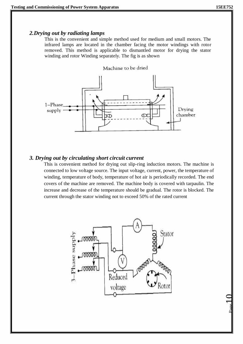
Testing and Commissioning of Power System Apparatus 15EE752
2. Drying out by radiating lamps This is the convenient and simple method used for medium and small motors. The infrared lamps are located in the chamber facing the motor windings with rotor
removed. This method is applicable to dismantled motor for drying the stator
winding and rotor Winding separately. The fig is as shown
3. Drying out by circulating short circuit current
This is convenient method for drying out slip-ring induction motors. The machine is
connected to low voltage source. The input voltage, current, power, the temperature of
winding, temperature of body, temperature of hot air is periodically recorded. The end
covers of the machine are removed. The machine body is covered with tarpaulin. The
increase and decrease of the temperature should be gradual. The rotor is blocked. The
current through the stator winding not to exceed 50% of the rated current
Pag
e10

Testing and Commissioning of Power System Apparatus 15EE752
Tests on Induction Motor
Type Test:These tests are conducted on the machine to confirm the design
Routine Test: These tests are conducted on each motor to confirm proper manufacture
and to ensure trouble free performance at a site
Commissioning Test: These tests are conducted after installation before final
commissioning to ensure the machine is free from defects
Special Test: These tests are conducted to analyze the performance or for special
investigation
Development Test: These tests are conducted to analyze the effect of various design
parameters and stresses
Reliability Test: These tests are conducted to access the reliability of motor
1. Insulation resistance test
The insulation resistance is done by using megger like transformer. (refer unit one and two
notes page 15-16) . If megger is not available we will go for volt-ammeter method.
2. Measurement of winding resistance
The following are the methods to measure the winding resistance of the motor
1. The Drop of Potential or Voltmeter- Ammeter Method: In this simple method DC voltage
and current are measured by using volt meter connect in parallel and by ammeter connected in
series with the winding, when the values became steady.
Pag
e11

Testing and Commissioning of Power System Apparatus 15EE752
Since the resistance between two terminals is usually of 2 phases are in series, the resistance
perphase
Rdc = V/2I
The ac resistance is 1.5 times dc resistance because of proximity effect skin effect of ac current.
Rac = 1.5Rdc = 1.5V/2I = 1.5Rdc
2. Kelivin- Thompson double bridge Method:Resistance less than 1 ohm shall be measured by
Kelvin double bridge. The winding is connected at unknow resistance terminal of the bridge. And
the resistance is determined by varying the variable resister until the galvanometer shows zero
deflection. The variation of resistance between phases to the extended of 5 % may be permitted.
3. High Voltage Test
The test is conducted to check the capability of insulation of windings. The test voltageis of power frequency and sine wave. The value of maximum test voltage at site test is given by the expression:
Vac(site)= 75%[2*rated voltage+1000] volts Vac= 1.5 rated line to line voltage
The test set up is shown in fig
Pag
e12

Testing and Commissioning of Power System Apparatus 15EE752
The three terminals of the motor are connected together and to the high voltage terminal of test supply. The body is earthed and is connected to the earth terminal of test supply. In this test, the test voltage is raised quickly to the maximum test voltage and applied for one minute and reduced slowly to zero.
If the breakdown occurs, the test supply is automatically tripped. The test is conducted on go/not go basis. While conducting the test, reference to the relevant standards and manufactures instruction is to be made.
4. No load Test
This test is conducted to determine the no-load current, core loss and friction and wind age losses. The motor is run on no-load at rated voltage and frequency until the input power is constant. The readings of voltage, frequency, current and power are noted. This test shall be preferably conducted immediately after the temperature rise test. The input power is the sum of friction and wind age losses, core loss and no-load primary I2R loss. The friction and wind age losses and core losses may be separated if required. The test setup is as shown.
5. Locked rotor test
This test is a carried out by holding the rotor stationary by clamps. The stator is supplied with low voltage of normal frequency. The applied voltage is gradually increased till the rated current is circulated in the stator windings. The readings of voltage, current and power are noted. The leakage impedance reduces with higher current as a result of saturation. Locked rotor test gives copper loss for particular stator current. Iron losses are ignored.
6. Load Test The test with the load are conducted for the determination of performance such as efficiency,
power factor, speed and temperature raise. For all the test with load, the machine shall be
properly aligned and secured fastened.
The motor may be loaded by AC or DC coupled generator either directly or by belt. The
output of generator is measured and its effeminacy at various loads must be known to
Pag
e13

Testing and Commissioning of Power System Apparatus 15EE752
calculate the output of the motor under test. The input to the motor is measured by using Watt
meters. When belt drive is used, the power loss in the belt should be considered. When a
pony break is used, for large machines, then break gets extremely hot, so the observation
must be taken very quickly. This method is suitable for small machines testing in the
laboratory.
7. Temperature rise test:
The aim of this test is to find out the temperature rise on different parts of the motor while running at rated conditions. During temperature rise test, the motor should be shielded from currents of air entering from adjacent pulleys and other machines. A small current of air may cause great discrepancy in results obtained. The duration of temperature rise test depends on the type of rating of the motor. For motors of continuous rating, the test should be continued till the thermal equilibrium is reached. For motors of short time rating the duration of test corresponds to the declared short time rating, the test should be continued till the thermal equilibrium is reached. Methods of measuring temp The following methods are approved for determining the temperature of windings and other parts of motor.
1) Embedded temperature detector method:
Embedded temperature detectors are resistance thermo-meters or thermocouples built in the machine at points which are inaccessible when the m chine is assembled. This method is generally employed for the slot portion of stator windings. At least six detectors to be built in a machine suitably distributed around the circumference.
2) Resistance Method:
This method is generally used for stator windings. Here temperature is determined by the increase in the resistance of the windings. The temperature is determined by the formula
T2 – Ta = x(235+T1)+T1-Ta
Where Ta – Temperature of cooling air at the end of the test T2 - Temperature of winding at the end of the test T1 - Temperature of winding at the time of initial resistance measurement R2 – Resistance of the winding at the end of the test R1 – Initial resistance of the winding
3) Thermometer method:
This method is used when temperature measurement by embedded detector and resistance method is not possible In this method, the temperature is determined by thermometers placed at the accessible surface of the rotor.
8. Determination of Slip of Induction Motor
a) Speed measurement method: In this method the speed of the motor is measured by tachometer. The slip is calculated by knowing the synchronous speed taking exact value of frequency of the applied voltage
Pag
e14

Testing and Commissioning of Power System Apparatus 15EE752
b) Stroboscopic Method: In this method, the disc is painted with alternate black and white strips and it is attached to motor shaft.The disc is illuminated by neon lamp from stroboscope.The complete apparent revolution of disc correspondence to slip per pair of poles. Slip is calculated using
c) Slip Coil Method: In this method, the insulated wire is passed axially over the motor and it’s 2 ends are connected to centre of galvanometer. When the motor is running the galvanometer pointer will oscillate. The number of oscillations shall be counted in one direction for a time ‘T’ seconds. Slip is calculated by
where n is number of oscillation
d) Magnetic Needle Method: The Magnetic needle is placed on the body of the motor horizontally. When the motor is running the needle will oscillate. The number of oscillations shall be counted in one direction for a time ‘T’ seconds. Slip is calculated by
where n is number of oscillation
e) Rotor Frequency oscillation measurement: The moving coil ammeter with centre zero is inserted in the rotor circuit to know the rotor frequency. The frequency can be found by counting the oscillation of the pointer Slip is calculated by
9. Noise in Motors
The noise of a rotating machine is generated by a cooling air from its fan as it passed through or over the machine. Some noise reduction is possible by substituting unidirectional trailing bladed fans by the normal radial blades Further reduction is achieved by inlet and outlet silencers or the adoption of closed ventilation circuit of cooling air. The noise is also caused by magnetic effects and dependent on the stator and rotor slots. It can occur in machine with fractional number of open slots per pole, producing a relatively
Pag
e15

Testing and Commissioning of Power System Apparatus 15EE752
a large vibration of air-gap flux density. This may produce a penetrating note at approximately slot frequency (e.g. 0.5 – 1.5kHz). The amplitude of stator permeance variation may be the cause, but the amplitude also depends on higher order rotor m.m.f. space harmonics. The frequency of the noise is twice the product of the supply frequency with that integer nearest to the number of slot per pole.
Noise Reduction:Noise is caused by 1. Magnetostriction, 2. Aerodynamics, 3. Bearing noise of rotating shaft
Speed and Power effect: - Totally enclosed machine give least sound. Open ventilated machine give
maximum sound. - Ventilation noise predominates in 2-pole machines - Magnetic noise is predominating in machines with more number of poles - When bearing, noise become audible, the other two become less significant
Methods to reduce the noise for DC Machine
- Reduced magnetic loading. - Increase number of armature slots – Skewing of slots. - Continuously graded main pole gap (more at pole end and least at pole centre) - Increase in air gap – Brace commutating poles against main poles - 12 pulse thyristor for speed control and not 6-pluse - Semi- enclosed slots or closed slots for compensating windings
INSTALLATION OF LARGE ROTATION MACHINE RECEVIED IN DISMANTLED CONDITION
Various steps in installation of a large rotation machine received in dismantled condition are:
Installation of bed plate and the leveling of bed plate
Installation of the bearing pedestals and leveling of the bearing
pedestals
Checks on stator and rotor
Assembly of the rotor onto the shaft
Installation of the stator
Installing the rotor in the stator
Checking of the air gap between stator and rotor
Installation of the the driven and drive machine in the similar fashion.
Preparation of shaft couplings
Mounting of shaft couplings on shaft
Preparation of shafts and alignment of shafts.
Installation of cooling systems
Drying out
Testing
Commissioning
Pag
e16

Testing and Commissioning of Power System Apparatus 15EE752
Each of the above activities should be carried out by technically skilled staff. The
instruction manual supplied by the manufacturer should be referred in practice. Shaft
alignment should be, perfect to get trouble free mechanical performance of the generator with the driven equipment. The rating plate is of definite dimensions as per IS
Code. The ratings are etched or engraved and is fixed to the machine in a clearly visible
position
Various Abnormal conditions & the Protections provided
The abnormal conditions in induction motor can be classified into:
1. Prolonged overloading: It caused due to the mechanical loading, short time cyclic overloading. this results in temperature rise of the winding and deterioration of the of insulation resulting in winding fault.
Protection: The motor should be provided with the overload protection, thermal overload relays and overload release.
2. Single phasing: one of the supply lines gets disconnected due to the rupturing of the
fuse or open circuit in one of three supply connections. In such case motor continues to
run with the single supply. If the motor is loaded to its full rate load, it draws excessive current on single phasing. The windings get overheated and damage the insulation of the
winding.
The single phasing also causes the unbalanced load resulting in excessive heating of the rotor due to negative sequence component.
Protection: the motor should be protected with the negative phase sequence relay, thermal overload relays and static single phasing relays.
3. Internal faults in the motor: It is mainly due to the overloading, abnormal supply conditions which results in failure of insulation resistance and temperature rise
Protection: the motor should be protected with the differential protection, over current relay the motor should be protected with the s,HRC fuses
4. Stalling: If the motor dos not start due to the excessive load, it draws heavy current . It should be immediately disconnected from the supply.
Protection: the motor should be protected with the thermal relays and instantaneous O.C
relays.
5. Excessive harmonics in supply voltage:
Protection: the motor should be protected with the AC harmonic filters connectecd near motor terminals
6. Switching surges:
Protection: the motor should be protected with the RC surge modifiers, Zno arresters near motor terminals
Pag
e17

Testing and Commissioning of Power System Apparatus 15EE752
Factors to be considered in selecting motors for Industrial drives Important factors to be considered in selecting motors for industrial drives are:
1. Relationship between size, weight,power,torque and speed of electric motor
The torque and speed determine the size of an electric motor. Machine of equal
power may deliver different torque at different speeds and thus be too different sizes. High speed motors are smaller than lower speed machines of the power.
2. Standardization and Type of motor, specifications.
Electric machines have different operating characteristics. Machine is designed to get particular characteristics and design feature. For the sake of greater uniformity, the size, power, speed voltages, power factors etc of electrical machines are
standardized.
3. Type of frame Different frame types of rotary electrical machines are categorized in DIN42950. The various frame types are denoted by letter/number codes. Three criteria used to differentiated types are 1) The bearing type 2) The form of stator 3) The position of shaft.
4. Types of Degree of protection
The electrical plants are exposed to different operating condition. The degree
of protection against these external influences is indicated by the type of
protection
5. Operating Duty and ratings
6. Cooling
The operating temperature of a machine depends on cooling as well as the load. If
large quantity of heat is removed by cooling, the machine can be loaded more.
Cooling systems according to their type and functions.
7. Insulation Class
The machine must be insulated in accordance with its voltage rating, power rating and duty cycle. The type of insulation used depends on the operating temperature.
8. Transmission of shaft power and interface with drive
The power output of an electric motor must be transmitted to the machinery it is driving. The two machines can be directly coupled. In this case their shafts speed will be identical torque and power are transmitted directly
9. Speed torque characteristics
10. Braking requirements
11. Maintenance requirements.
Preventive maintenance schedule of Induction motor
The objective of the maintenance is to reduce the number of failures. During normal
working, some parts wear out and calls for replacement and minor defects are to be rectified
to avoid failure. The breakdown of motor results in loss / damage /outage /inconvenience.
The down time of the machine must be kept as minimum as possible. Hence preventive
maintenance is justified
The preventive maintenance needs
Proper records
Skilled labor and staff
Facilities for repairs
Pag
e18

Testing and Commissioning of Power System Apparatus 15EE752
Storage of spares
The repeated inspection leads to wastage of time and money. The neglected/hardly Inspection leads to failure. The frequency of inspection must depend on
Importance of the machine
Duty cycle
Age
Overloads, service conditions
The maintenance schedule is always recommended by the manufacture
EVERY WEEK
1. Examine commutator and brushes, ac and dc.
2. Check oil level in bearings.
3. See that oil rings turn with shaft.
4. See that exposed shaft is freeof oil and grease from bearings.
5. Examine the starter switch, fuses, and other controls; tighten loose
connections.
6. See that the motor is brought up to speed in normal time.
EVERY SIX MONTHS
1. Clean motor thoroughly, blowing out dirt from windings, and wipe commutator and brushes.
2. Inspect commutator clamping ring.
3. Check brushes and replace any that are more than half worn.
4. Examine brush holders, and clean them if dirty. Make certain that brushes ride free in the holders. 5. Check brush pressure.
6. Check brush position.
7. Drain, wash out, and replace oil in sleeve bearings.
8. Check grease in ball or roller bearings.
9. Check operating speed or speeds.
10. See that end play of shaft is normal.
11. Inspect and tighten connections on motor and control.
12. Check current input and compare it with normal.
13. Examine drive, critically, for smooth running, absence of vibration, and worn gears, chains, or belts.
14. Check motor foot bolts, end-shield bolts, pulley, coupling, gear and journal set screws, and keys.
15. See that all covers, and belt and gear guards are in place, in good order, and securely fastened.
Pag
e19

Testing and Commissioning of Power System Apparatus 15EE752
ONCE A YEAR
1. Clean out and renew grease in ball or roller bearing housings.
2. Test insulation by megohmmeter.
3. Check air gap.
4. Clean out magnetic dirt that may be clinging to poles.
5. Check clearance between shaft and journal boxes of sleeve bearing motors to pre vent operation with worn bearings.
6. Clean out undercut slots in commutator. Check the commutator for
smoothness.
7. Examine connections of commutator and armature coils.
8. Inspect armature bands
Pag
e20
Testing and Commissioning of Power System Apparatus (15EE752)
Module-4 laying of Underground cables
Syllabus:
Laying of Underground Cables: Inspection, Storage, Transportation and Handling of
Cables, Cable Handing Equipment, Cable Laying Depths and Clearances from other
Services such as Water Sewerage, Gas, Heating and other Mains, Series of Power and
Telecommunication Cables and Coordination with these Services, Excavation of Trenches,
Cable Jointing and Terminations Testing and Commissioning. Location of Faults using
Megger, Effect of Open or Loose Neutral Connections, Provision of Proper Fuses on Service
Lines and Their Effect on System, Causes and Dim, and Flickering Lights.
Introduction:
An underground cable essentially consists of one or more conductors covered
with suitable insulation and surrounded by a protecting cover.
Although several types of cables are available, the type of cable to be used will
depend upon the working voltage and service requirements.
In general, a cable must fulfill the following necessary requirements:
(i) The conductor used in cables should be tinned stranded copper or
aluminum of high conductivity. Stranding is done so that conductor may
become flexible and carry more current.
(ii) The conductor size should be such that the cable carries the desired load
current without overheating and causes voltage drop within permissible
limits.
(iii) The cable must have proper thickness of insulation in order to give high
degree of safety and reliability at the voltage for which it is designed.
(iv) The cable must be provided with suitable mechanical protection so that it
may withstand the rough use in laying it.
(v) The materials used in the manufacture of cables should be such that there
is complete chemical and physical stability throughout.
The reliability of underground cable network depends to a considerable extent upon
the proper laying and attachment of fittings i.e., cable end boxes, joints, branch
connectors etc.
There are three main methods of laying underground cables viz.,
1. direct laying,
2. draw-in system
3. Solid system.
1. Direct laying:
This method of laying underground cables is simple and cheap and is much favored in
modern practice.
In this method, a trench of about 1•5 meters deep and 45 cm wide is dug.
The trench is covered with a layer of fine sand (of about 10 cm thickness) and the
cable is laid over this sand bed.
Pag
e1

Testing and Commissioning of Power System Apparatus (15EE752)
The sand prevents the entry of moisture from the ground and thus protects the cable
from decay.
After the cable has been laid in the trench, it is covered with another layer of sand of
about 10 cm thickness..
Advantages
1. It is a simple and less costly method.
2. It gives the best conditions for dissipating the heat generated in the cables.
3. It is a clean and safe method as the cable is invisible and free from external
disturbances.
Disadvantages
1. The extension of load is possible only by a completely new excavation which
may cost as much as the original work.
2. The alterations in the cable network cannot be made easily.
3. The maintenance cost is very high.
4. Localization of fault is difficult.
5. It cannot be used in congested areas where excavation is expensive and inconvenient.
This method of laying cables is used in open areas where excavation can be done
conveniently and at low cost.
2. Draw-in system:
In this method, conduit or duct of glazed stone or cast iron or concrete are laid in the
ground with manholes at suitable positions along the cable route.
Three of the ducts carry transmission cables and the fourth duct carries relay
protection connection, pilot wires.
Care must be taken that where the duct line changes direction; depths, dips and offsets
be made with a very long radius or it will be difficult to pull a large cable between the
manholes. The distance between the manholes should not be too long so as to simplify
the pulling in of the cables.
The cables to be laid in this way need not be armored but must be provided with
serving of hessian and jute in order to protect them when being pulled into the ducts.
Advantages
(i) Repairs, alterations or additions to the cable network can be made without
opening the ground.
(ii) As the cables are not armored, therefore, joints become simpler and
maintenance cost is reduced considerably.
(iii) There are very less chances of fault occurrence due to strong mechanical
protection pro-vided by the system.
Disadvantages
Pag
e2

Testing and Commissioning of Power System Apparatus (15EE752)
(i) The initial cost is very high.
(ii) The current carrying capacity of the cables is reduced due to the close
grouping of cables and unfavorable conditions for dissipation of heat.
3. Solid system:
In this method of laying, the cable is laid in open pipes or troughs dug out in earth
along the cable route.
The toughing is of cast iron, stoneware, asphalt or treated wood.
After the cable is laid in position, the troughing is filled with a bituminous or asphaltic
compound and covered over.
Cables laid in this manner are usually plain lead covered because troughing affords
good mechanical protection.
Disadvantages
(i) It is more expensive than direct laid system.
(ii) It requires skilled labor and favorable weather conditions.
(iii) Due to poor heat dissipation facilities, the current carrying capacity of the
cable is reduced.
Transport and Handling of Cables:
It is possible to store cable drums outdoors.
When storage has occurred in heated rooms, a minimum 24-hour acclimatization
period must be observed before installation
For outdoor storage the ground must be even and clean.
Stones or bumps in the ground should be removed or smoothed out.
Damage to the wound goods/cable should be avoided at all costs.
Cables should be secured against accidental rolling away.
Under no circumstances should the drum flange of neighboring cables touch any
wound goods.
Cable drums should always be stored and transported standing on both flanges.
They should not be pushed along the ground standing on the flanges.
It is possible that the strength of the cable drum would then no longer be guaranteed.
Observe the rolling direction.
The arrow printed on the drum flange indicates the rolling direction so that the
wound goods do not become loose.
Always uncoil the cable at a tangent, never over the flange, since the torsion thus
resulting would damage the cable and laying would not be possible.
Underground Cable Testing
The cables are tested for the following faults:
1. Short Circuiting
2. Discontinuity
Pag
e3

Testing and Commissioning of Power System Apparatus (15EE752)
3. Earth fault
Murray Loop Test For finding out the exact position of fault, cables are to be repaired
without digging the whole cable route trench.
For this purpose, the Murray loop test which is based upon the principle of wheat-
stone bridge, and bridge Megger is used.
The Murray loop test is used for the location of faults on lines of low resistance, such
as power cables and telephone cables.
Cable fault location:
Cable fault location is required anywhere where the fault cannot be seen.
This is a multi-step process that must be performed as safely and as quickly as
possible to prevent customers going without power.
Step 1 –
Cable isolation and safety procedures: A cable fault is nearly always a
permanent fault.
This means that the cable in question will be in a condition where the protection
devices at one or both ends of the cable will have tripped, leaving the cable
isolated but NOT earthed (grounded).
The first task is for the authorized person on the site to make the cable safe by
isolating and then earthing (grounding) one or both ends.
Only after the appropriate procedures have been carried out can any testing
personnel be allowed to approach the cable and prepare for testing.
Step 2 –
Cable identification: Where multiple cables exist, cable identification testing will
identify the correct cable to work on.
Clear identification before a cable is cut is intrinsic to safe maintenance work.
Any mistakes here can be fatal and may cause much longer outages for the connected
customers.
Step 3 –
Cable tracing: When an underground cable is first laid, it rarely runs in a straight
line, but rather meanders in depth and direction.
Cable tracing is done to determine that the route of the cable is following the
expected path.
Step 4 –
Fault identification: The first major procedure is to determine the phase on which the
fault has occurred and if it is of low or high resistance.
This test determines the correct technique, and therefore equipment, needed to
diagnose the fault.
Pag
e4
Testing and Commissioning of Power System Apparatus (15EE752)
Typically, if the fault is found to be below 100 Ohms, a low voltage pulse (eg: 40 V)
from a TDR (time domain reflect meter) can be used.
If the fault is a higher resistance (> 100 Ohm), a low voltage pulse will likely not see
it. For these types of faults, an impulse generator (shock discharge) or bridge, will be
necessary.
Step 5 –
Fault prelocation: A reliable and precise pre-location method is necessary to
locate a cable fault quickly and efficiently.
Good pre-location can determine the fault position to within a few percent of the
cable length and will reduce pinpointing time to a few minutes.
Remember:
a) If it is a low resistance fault, pre-location is likely to be the only means necessary for
location.
b) For high resistance faults, ARM (arc reflection) or ICE (impulse current) techniques on an
SWG (surge wave generator) should be used. Alternatively, the decay method with an HV
DC tester (bridge) can be used for pre-location.
Step 6 –
Pinpointing: The aforementioned test methods will get the operator within 5%
distance of the fault.
Acoustic pinpointing techniques must be employed at this stage in order to narrow the
margin of error to 0.1%.
In most cases, shock discharge generators are used for pinpointing in conjunction
with acoustic methods.
The discharge creates a loud noise, which is pinpointed precisely using an acoustic
pinpointing device.
This device evaluates the time difference between the acoustic signal (speed of
sound) and the electromagnetic (nearly the speed of light) impulse of the shock
discharge.
When the shortest time difference is indicated, the exact fault location is revealed.
Step 7 –
Re-energization of the cable: Once all testing and repairs are completed, the
Safety/Testing documentation is cancelled and the cable is handed back to the
appropriate operators so they can reinstate it and re-energies the loads on the
newly repaired cable.
Pag
e5

Testing and Commissioning of Power System Apparatus (15EE752)
Syllabus:
Module 5
SWITCHGEAR AND PROTECTIVE DEVICES
Switchgear and Protective Devices: Standards, Types, Specification, Installation,
Commissioning Tests, Maintenance Schedule, Type and Routine Tests.
Domestic Installation: Introduction, Testing of Electrical Installation of a Building, Testing
of Insulation Resistance to Earth, Testing of Insulation and Resistance between Conductors
Continuity or Open Circuit Test, Short Circuit Test, Testing of Earthing Continuity, Location
of Faults, IE Rules for Domestic Installation
Introduction:
The term switchgear includes wide range of equipment used for switching,
interruption, measurement, control, indication etc.
The necessary units are arranged in a sequence.
The components are enclosed in sheet metal enclosure or cast iron enclosures.
Hence the name metal clad switchgear or metal enclosed switchgear.
The components of indoor switchgear include
(1) switching and interruption components viz. switches, switch fuse combinations,
circuit breakers, HRC fuses, isolators and earthling switches
(2) measuring components viz. CT, PT, meters etc.
Faults occur on power system due to several reasons and no part of the power system
is left unprotected.
The unhealthy part is isolated immediately upon the occurrence of the fault by
protective devices like relays and circuit breakers.
The functions of different devices used in protection are mentioned below.
1. Relay: It is used to sense the change in the operating quantity when it exceeds certain
preset value.
2. Fuse: It is a simple protective device which breaks the circuit when the current exceeds
the rated value. After the clearance of the abnormality, the fuse element is to be replaced
to resume normal operation.
3. Circuit breaker: It is used to break or make the circuit upon receiving the signal from
the associated relay under abnormal and normal conditions respectively. Based on the
location the making may be manual, semi-auto enclosure or auto closure.
4.Isolators: Isolators are used to isolate during off-load to ensure that the circuit breaker is
de energized for scheduled or unscheduled maintenance activity and is provided with
interlocking provision.
5. Load break switch: This is used to disconnect the load and overload currents and not
short circuit current.
Pag
e1

Testing and Commissioning of Power System Apparatus (15EE752)
Circuit breaker
A circuit breaker is capable of breaking & making the circuits under abnormal and
normal conditions respectively.
The parts of circuit breaker include
a) Poles with interrupter, porcelain, arc quenching medium
b)Operating mechanism
c) Support structure
d) Control cabinet
Upon the occurrence of the fault, the current in the secondary side of CT is more than
the current under normal condition and relay connected to the CT actuates and
thereby closes its contacts.
Battery supplies the" current to energize the trip coil of the circuit breaker to open the
contacts.
After resuming the normal condition, the battery circuit is open & circuit breaker
contacts are closed.
Types of circuit breaker
According to the method of control of the closing operation, circuit breakers are
classified as (IS 1011 (Part-II)-1982).
1. Dependent manual closing
2. Independent manual closing
3. Dependent power closing
4. Stored energy closing
According to the interrupting medium, circuit breakers are divided into
1. Oil circuit breakers
2. Bulk oil circuit breaker - up to 33 KV (now obsolete).
3. Minimum oil circuit breaker - up to 36 KV, 1500 MVA, 132 KV, 3500 MVA
4. Air circuit breaker - LV circuit breaker up to 1000 V
5. Air blast circuit breaker - 132 KV, 220 KV, 400 KV, 760 KV
6. Sulfur hexafluoride circuit breaker - 132 KV, 220 KV, 400 KV, 760 KV
7. Vacuum circuit breaker - 11 KV, 33 KV
The type of equipment is also further characterized by
o Number of poles
o Kind of current
o Method of closing
o Method of opening
Specifications of high voltage circuit breaker
Rated voltages: A circuit breaker is defined by the following rated voltages
Rated operational voltage , Rated insulation voltage
Pag
e2

Testing and Commissioning of Power System Apparatus (15EE752)
Rated current: The circuit breaker is defined by the following currents rated thermal current
rated uninterrupted current
Rated frequency: The rated frequency of the equipment is so chosen as to suit the service
frequency Rated short circuit breaking and making capacities:
The rated short circuit breaking current is the highest value of short circuit current
which the circuit breaker is capable of breaking under specified conditions of
recovery voltage and power frequency recovery voltage.
The rated making current must be at least 2.5 times the rms value of ac component of
rated breaking current.
Rated short time withstand current: It is the rams value of the current that the circuit
breaker can carry in a fully closed position during specified time.
Short circuit performance category: The rated short circuit performance category
of the equipment states the rated operating sequence and the condition of the circuit
breaker after performing this sequence at the rated short circuit making and breaking
capacities.
For the same circuit breaker the value of the rated short circuit breaking and
corresponding making capacities may be different for different short circuit
performance categories.
The following characteristics should also be considered while selecting the circuit
breakers.
a) For control circuits: Rated control supply voltage and type (ac or dc) of current.
b) For air supply system: Rated pressure and its limits and volumes of air at
atmospheric pressure required for each closing and opening operation.
C) For shunt release and under voltage release: Rated voltage & kind of current.
d) For over current release: Rated thermal current, kind of current and range of
settings.
e) For auxiliary switches: Rated voltage & current The circuit breakers intended for
circuit operating below 1000 volts ac or 1200 volts dc are covered under the group
low voltage circuit breaker.
Tests on circuit breakers
Type tests: These tests are conducted on the first circuit breaker manufactured to prove the
capabilities and to confirm the specified characteristics of the circuit breaker of that design in
a specially built testing laboratory.
Routine test: Routine tests are performed on each and every circuit breaker as per the
recommendation of the standards to verify the performance.
Commissioning tests: These tests are conducted on the circuit breaker after installation at
site to verify the readiness and proper functioning.
Development tests: These tests are carried on components, sub-assemblies and complete
circuit breakers during and after the development of the circuit breaker. The designers and
research scientists verify the effect of various parameters.
Pag
e3

Testing and Commissioning of Power System Apparatus (15EE752)
Types of test:
1. No Load mechanical operation test: This test is to verify speed of travel, operating time
and closing time and is carried out at 85% and 110% rated voltage of shunt trip release.
2. Mechanical performance tests (endurance): It is to check the mechanical ability of opening
and closing of the contacts by carrying out 1000 close and open operations or more.
3. Temperature rise test: Steady temperature of conducting part and insulating parts measured
for rated continuous alternating current.
4. Dielectric tests:
1.2/50 IPSec Lightning impulse withstand
One minute power frequency voltage withstand
250/2500 Ills switching impulse withstand
5. Short time current test: Rated short circuit current is passed through closed breaker for less
or 3 secs.
6. Short circuit breaking and making tests: This test is conducted at 10%, 30%, 60% and
100% rated short circuit braking current with specified operating sequence and specified
TRV (transient recovery voltage).
7. Line charging current breaking test: This test is conducted for circuit breakers 72.5 KV and
above.
8. Cable charging current breaking test: This test is applicable to circuit breakers intended for
long cable network.
9. Single capacitor bank breaking test: This test is applicable for circuit breakers used for
capacitor switching.
10. Small inductive current breaking test: This test is to be conducted on circuit breakers with
reactors, transformers, motors etc.
Commissioning tests:
After the installation, the circuit breakers and protective gear are subjected to certain
tests at site to ensure proper assembly and readiness of the circuit breaker.
The commissioning tests include:
Mechanical operation tests
Measurement of travel, simultaneous closure of contacts Measurement of insulation
resistance between terminals of pole Pre commissioning checks
Checking close and open operation by energizing the manual operating signal
Checking close and open operation by energizing relays etc
The insulation resistance is measured using Megger. It consists of a built in hand
driven dc generator.
The two terminals of Megger are connected across the insulation i.e. one to the
conductor and other to the earthed body.
Pag
e4

Testing and Commissioning of Power System Apparatus (15EE752)
Then the dc generator is driven & corresponding resistance indicated by the Megger
is recorded.
For the switchgear 1000V or 2500V mugger is preferred.
Insulation resistance of the control circuit, trip circuit, relay circuit etc. is measured
using 500V mugger.
High voltage test at site
High voltage test as per the relevant IS code is conducted after the erection of the
circuit breaker.
By conducting this test the defect in the insulation can be checked.
The test voltage is generally applied for duration of one minute.
The circuit breaker is isolated suitably during the test.
The test voltage is applied between the to be 'tested part' and earthed parts as follows.
1) With breaker closed:
a) Tested part: R – phase earthed part: Y - phase, B - phase, frame of the circuit breaker
b) Similarly for the phase Y and B
2) With breaker open: This test is conducted on breaker contacts by shorting R, Y, B phases
on bus bar side~ Voltage is applied from other side consecutively to each phase.
The purpose of high voltage test on circuit breaker is as follows:
To define the insulation characteristics
To standardize the insulation levels
To specify the markings on the rating plates indicating insulation levels
To confirm that, there are no cracks in porcelain, no dust and moisture is present in the
circuit breaker
High voltage tests on circuit breaker include the following.
Impulse voltage dry withstand test One minute power frequency voltage dry withstand test.
One minute power frequency voltage wet withstand test Power frequency voltage
withstand tests are conducted by applying specified high voltage alternating quantity
for one minute.
High voltage testing transformer is an important component of the high voltage
testing of circuit breakers.
Sphere gaps are used for the measurement of high voltage.
The sphere gap gives the peak voltage from the known spacing and standard table, the
peak Voltage at the instant of disruptive discharge can be obtained.
Temperature rise test
This test is to be conducted on a circuit breaker that is the representative of a batch of
circuit breakers manufactured
Alternating current of rated value at rated frequency is passed through the circuit
breaker by keeping the contacts in the closed position, continuously till the steady
temperature is reached.
Pag
e5

Testing and Commissioning of Power System Apparatus (15EE752)
Readings of various conducting, insulating and structural parts are taken at an interval
of one or half an hour.
When steady temperature is reached, the maximum temperature rise of each part
should be less than the permitted values.
Mechanical test (Endurance test)
The breaker should consistently open and close its contacts. In mechanical endurance
test the circuit breaker is opened and closed many times (nearly 1000 times).
Few opening & closing operations (nearly 50 times) is done by energizing the relay
and the remaining are by closing the trip circuit by other means.
Mechanical tests on high voltage ac circuit breakers are conducted without charging
the main circuit.
During mechanical tests adjustment or replacement of any part of the circuit breaker
is not allowed.
However lubrication is to be applied as per the instructions of the manufacturer. After
repeated closing and opening operation, the contacts and other parts of circuit breaker
must be in good position and there should not be any permanent deformation of any
parts.
The dimensions should be within original limits.
During repeated operations, the breaker parts in the assembly may fail.
The circuit breaker is then considered to have failed in the mechanical test.
The tests are to be conducted after the improvement in the design and manufacture.
Test for contact resistance of circuit breaker pole
This is measured by one of the following two methods.
1) Micro ohmmeter: A micro ohmmeter is connected across terminals of the pole to
measure the resistance directly.
2) Mill volt drop method: The voltage drop across the circuit breaker pole is measured for
different values of dc current. The voltage drop gives a measure of current carrying part and
contacts. The dc current should be sufficiently high but must be less than the rated current.
The resistance measurement of circuit breaker pole should be done at ambient temperature.
The resistance must be of the order of few tens of micro ohms. This test is a routine test to be
carried out to ascertain the performance when the circuit breaker is put in actual operation.
Impulse voltage test
This test is carried· out on indoor and outdoor circuit breakers. Standard impulse
wave of specified amplitude is applied five times in succession.
During the test impulse wave with reversed polarity is also applied.
The impulse wave is obtained from an impulse voltage generator.
One terminal of the impulse generator is connected to the terminal of the circuit
breaker pole and the other terminal is connected to the earth and frame of the circuit
breaker.
The peak value of the impulse wave and its shape is recorded using RO with
calibrated voltage divider.
The different impulse voltages will have different front Wave and tail wave.
During the test if there is failure of the insulation or puncture, will be considered as
the circuit breaker has failed.
Pag
e6

Testing and Commissioning of Power System Apparatus (15EE752)
Selection of circuit breakers:
Circuit breakers are used at various voltage levels. The following factors are to be given consideration while selecting the circuit
breakers.
1) Ratings
2) Break time
3) Ambient conditions
4) Type; indoor or outdoor
5) Control desired
6) Type of operating mechanism
7) Type of breaker based on arc extinction medium
8) To be operated alone or in group
9) Frequency of operation
10) Other protective equipment’s with which to be co-ordinate
Installation procedure for circuit breakers:
In the process of installation of circuit breakers, the preliminary preparations such as
study of drawings, acceptance, report checking certificates, test reports of the
equipment, completion of civil engineering work, arranging the tools, organizing the
labor, preparation of schedule of installation, preparation of sequence cards for
erection etc. are to be done.
The different steps of installation include:
1) Sequence card for erection of switchgear equipment
2) Location of switchgear
3) Unpacking
4) Foundation
5) Erection
6) Bus bar earthling connections
7) Connection of main cables
8) Earthing
Ratings of LV circuit breakers
The important ratings of low voltage circuit breakers are as follows
Rated voltage and frequency
Rated currents
Rated duty
Rated short circuit making and breaking capacity
Rated short time withstand categories
Rated voltages: Rated operational voltage, rated Insulation voltage
Rated currents: Rated thermal current, rated uninterrupted current
Rated duty: short time, uninterrupted duty
Rated short circuit making capacity
Rated short circuit breaking capacity
Pag
e7

Testing and Commissioning of Power System Apparatus (15EE752)
Tests on low voltage ac circuit breakers
The different tests to be carried out on live circuit breakers are as follows.
Type tests: To be conducted to confirm the design, on the first piece manufactured.
Temperature rise limits test
Dielectric tests
Short circuit making and breaking tests
Short time withstand current test
Mechanical endurance test
Overload performance
Routine tests: To be conducted to predict the performance behavior on each circuit breaker.
Mechanical operation tests
Calibration of releases
Dielectric tests
Insulation resistance test
For low voltage load control, the switchgear used may be one of the following
Low voltage air breaks circuit breaker
Low voltage contactor
Switch fuse combination
Miniature circuit breaker
Molded case breaker
Maintenance of circuit breakers
The circuit breaker is intended for repeated operations as the occurrence of the faults
in the system is unpredictable.
Hence to ensure the protection of system components, more emphasis is to be given to
the maintenance of circuit breakers.
The maintenance procedure differs from breaker to breaker based upon the quenching
medium used.
The maintenance to be carried out includes the following.
1) Period of maintenance under normal condition on clearing faults
2) Checking of contacts
3) Checking of arc control devices
4) Checking of insulators
5) Checking of relays
Pag
e8

Testing and Commissioning of Power System Apparatus (15EE752)
Precautions to be taken during maintenance:
The maintenance work should be carried out with authentic permission by the
concerned authority.
The following steps are to be followed.
1) Isolate the live part
2) Danger notices should be displayed
3) The neighboring switch should be locked to avoid accidental switch nag
4) The equipment and conductors should be earthed
5) Power tools and safety devices to be provided to the electricians
6) Well trained people must be allowed for the work
7) First aid should be available
8) There should not be any chance of negligence
HVDC circuit breaker
In HVDC system, dc current is controlled by blocking the valves.
The arc extinction in ac circuit breakers takes place at natural current zero of the
wave.
Thus, the energy in system inductance at current zero is nil and current interruption is
relatively easy.
In dc system a LC resonant circuit is introduced in parallel, just after contact
separation of main circuit breaker, thereby oscillations are produced artificially
The circuit breaker uses one of the current zeros so as to extinguish the arc.
Such breakers are used for transferred nag current from earth return path to metallic
return
Fuses
Fuse is the weakest link in electrical circuit. It is the simplest current interrupting device used to protect from excessive
currents.
It is used for low voltage applications.
However modern High Rupturing Capacity cartridge fuses (HRC) provide reliable
discrimination and accurate characteristics.
In some respects HRC fuses are superior to circuit breakers.
The main difference between the two is that, fuse can break the circuit under
abnormal conditions but cannot make the circuit on its own after the system returns to
normal condition.
Types of fuse:
1. Semi enclosed or re wearable fuse
2. Totally enclosed or cartridge type
3. D-type
4. Bolted type
5. Expulsion fuse
6. High Rupturing capacity fuse (HRC)
Pag
e9

Testing and Commissioning of Power System Apparatus (15EE752)
The following details pertaining to fuse are considered while selecting the fuse for
particular application.
Rated current
Minimum fusing current
Perspective current
Pre-arcing time
Arcing time
Total operating time
Fusing factor
Pag
e10