Embed Size (px)
Citation preview

Eurographics/SIGGRAPH Symposium on Computer Animation (2003)D. Breen, M. Lin (Editors)
Stylizing Motion with Drawings
Yin Li, 1† Michael Gleicher2, Ying-Qing Xu3, Heung-Yeung Shum3
1 University of Science and Technology, Hong Kong2 University of Wisconsin, Madison3 Microsoft Research Asia, Beijing
AbstractIn this paper, we provide a method that injects the expressive shape deformations common in traditional 2Danimation into an otherwise rigid 3D motion captured animation. We allow a traditional animator to modifyframes in the rendered animation by redrawing the key features such as silhouette curves. These changes are thenintegrated into the animation. To perform this integration, we divide the changes into those that can be madeby altering the skeletal animation, and those that must be made by altering the character’s mesh geometry. Topropagate mesh changes into other frames, we introduce a new image warping technique that takes into accountthe character’s 3D structure. The resulting technique provides a system where an animator can inject stylizationinto 3D animation.
Categories and Subject Descriptors(according to ACMCCS): I.3.7 [Computer Graphics]: Animation
1. Introduction
Characters in traditional animation are remarkably expres-sive: they can change any aspect of their appearance in re-sponse to anything. Their appearance can depend on theirnormal shape, their pose, their mood, the direction they arebeing viewed from, or anything the animator desires. Howthey appear at one instant in time may be different from howthey appear at any other time. Good animators can use thistotal control over characters’ appearance to give charactersremarkable amounts of personality and expressiveness, oftenexaggerating elements for emphasis or purposefully shapingthe apparent silhouette to make the character easier to “read.”The cost of this freedom is a burden on the animator: notonly can all aspects of a character be controlled, theymustbe controlled.
Parametric 3D character animation offers a different bal-ance of control and effort. For example, the animator maycontrol the angle of an elbow, causing the arm to bend appro-priately. With a well-designed model, muscles might bulge
† e-mail: [email protected] This work was done when Yin was workingwith Microsoft Research Asia for his internship.
as the arm flexes. However, any changes in appearance mustbe driven by the parameters. The animator cannot adjust theappearance in response to the character’s situation - for ex-ample to make the muscle weak in fear, or have a strongersilhouette shape so it is more clear - unless this type of con-trol was specifically designed into that parameterization.
In motion captured animation, these problems are exac-erbated. Motion capture data provides the overall pose ofthe character, a skinning model creates a 3D shape from thispose, and 3D viewing creates the final appearance. There islittle opportunity for an animator to inject expression. There-fore, the resulting animation often lacks the appeal of tradi-tional animation because the motion is copied from reality,and the shape and appearance of the character is not tuned tothe specific needs of the moment of the animation.
Our goal is to inject some of the expressiveness of tra-ditional 2D animation into motion captured 3D animation.To do this, we provide a tool that allows traditional 2D ani-mators to use their talents to enhance the more realistic 3Danimation. We give the animators total control over the char-acters’ appearance at specifickeyinstants, allowing them tocreate the situation specific effects that give traditional ani-mation its distinctive style. We call the act of adding situa-tion specific effectsstylization.
To utilize animators traditional skills, we allow them tocontrol the characters through 2D drawings. The disadvan-
c© The Eurographics Association 2003.

Yin Li et al / Stylizing Motion with Drawings
Figure 1: Top: Original 3D model with motion capture data 2D. Bottom: Stylized animation driven by same motion capturedata
tage is that 2D drawings do not uniquely specify a 3D con-figuration. In order to integrate a drawing into an animation,we must guess an interpretation of the 2D sketch. This prob-lem is ill-posed. Rather than trying to solve this impossibleproblem, we instead focus on decreasing the need for correctsketch interpretation.
A key technical challenge of our work is integrating thechanges to nearby frames of the animation with smooth tran-sitions. We need a warping method capable of handling largedisparities with large amount of complexity. Our method de-composes the disparity into two parts: those that can be ac-complished by altering the skeletal animation of the charac-ter, and those that must be accomplished by altering the po-sitions of individual vertices of the character’s surface. Theskeletal changes can encode large amounts of change to theoverall character and are easy to integrate into the animation,while detailed displacements are capable of representing ar-bitrarily detailed changes, but are more difficult to integrateinto the animation. To address this latter issue, we provide asemi-automatic correspondence mechanism that makes useof hand-drawn images as well as 3D meshes, and a novelimage warping method that accounts for the character’s 3Dstructure.
In this paper, we introduce our approach for empower-ing traditional animators to add personality to 3D motioncaptured animation. We begin by discussing an example, toillustrate the components of the technique as well as to artic-ulate the workflow and interaction requirements. A survey ofrelated work shows that existing approaches do not addressour problem, but provide some building blocks for our work.In Section 3, we describe our methods for specifying the de-sired changes, transferring them to the 3D model, and prop-
agating them into the animation. We conclude with exampleresults and an evaluation of the limitations of our approach.
1.1. An Example: The Users Perspective
We introduce our approach from the user’s perspective.Frames from the initial input and final results are shown inFigure 1. We begin with an animation created by applying amotion captured dance movement to a model of an ant char-acter, as seen in the top of the figure. The “cartoony” charac-ter design rendering style suggests a cartoony motion. Whilethe movements may be realistic if applied to a human†, theyare inappropriate for the character. Human movements seemstiff, conservative, and rigid in an otherwise cartoon anima-tion.
To improve the animation, an animator selects frames toedit. In this example, an experienced 2D animator has cho-sen two frames where the ant is sticking out its leg (one tothe left and one to the right). She then redraws the outlineand key features of the character using the 2D drawing toolsshe is familiar with, as seen in Figure 2. The updated draw-ings are different from the original: she exaggerates the sizeof the extended leg to emphasize the kicking motion; shecurves the bent leg to make it appear more flexible and tomake the dip deeper and more energetic; she bends the an-tennae to make the character less rigid; she puts a happierfacial expression on the character’s face; she adds a finger tothe character’s outstretched hand; etc. In short, she uses hertalents as an animator and her insight into the ant’s person-ality and actions in a way that may never be automatable.
† It would be hard to call any movement of a smiling 4 legged antrealistic.
c© The Eurographics Association 2003.

Yin Li et al / Stylizing Motion with Drawings
(a) (b) (c) (d) (e)
Figure 2: (a) The motion captured movement is stiff and lacks personality. (b) The example image was drawn by the animator tobetter express the character’s personality. (c) After motion editing, the posture is closer to the example image. (d) After layeredwarp, the mesh is warped to the example drawing’s shape. (e) at another time, the warping field is propagated.
Our system must now integrate her new drawings into theanimation in a seamless manner. We call the new hand drawnimages theexamples,and the original computer drawingimage sequence therenderings. Each example correspondsto one of the renderings. Because the example might havea considerably different appearance than its correspondingrendering, we consult a user (who need not be the animator)to help specify the connection between the two.
Our approach divides the differences into two parts: thosethat can be achieved within the framework of the 3D skele-tal animation, and those that cannot. We first attempt to ac-count for the differences between the rendering and exampleby altering the 3D skeletal animation. We alter the pose ofthe skeleton, adjusting its joint angles and segment lengthsso that the rendered character appears to match the exampledrawing as closely as possible. At present, this is an interac-tive process, where the example image is overlayed on topof a 3D view of the character and the user can employ for-ward and inverse kinematics to adjust the pose. Views of thisprocess can be seen in Figure 4.
Adjusting the pose of the 3D skeleton cannot achieve allof the differences between the original rendering and theexample image. Our system requires the user to specify asmall number of corresponding points on each, as shown inFigure 5. The system then generates a seamless transitionbetween the original rendered animation and the exampleframe. This transition occurs over a user-specified durationof time (usually a fraction of a second). The result of theprocess is a new animation that is similar to the original, butcontains the example image.
Our process is optimized for characters that are createdby driving a skin from an underlying skeleton using blend-based skinning. Such skinning methods are supported byall animation systems, and most interactive runtime engines.Our system uses the skinning and skeletal motion informa-tion in creating the transitions between the rendered and ex-ample images.
1.2. Technical Overview
There are three key insights behind our work:
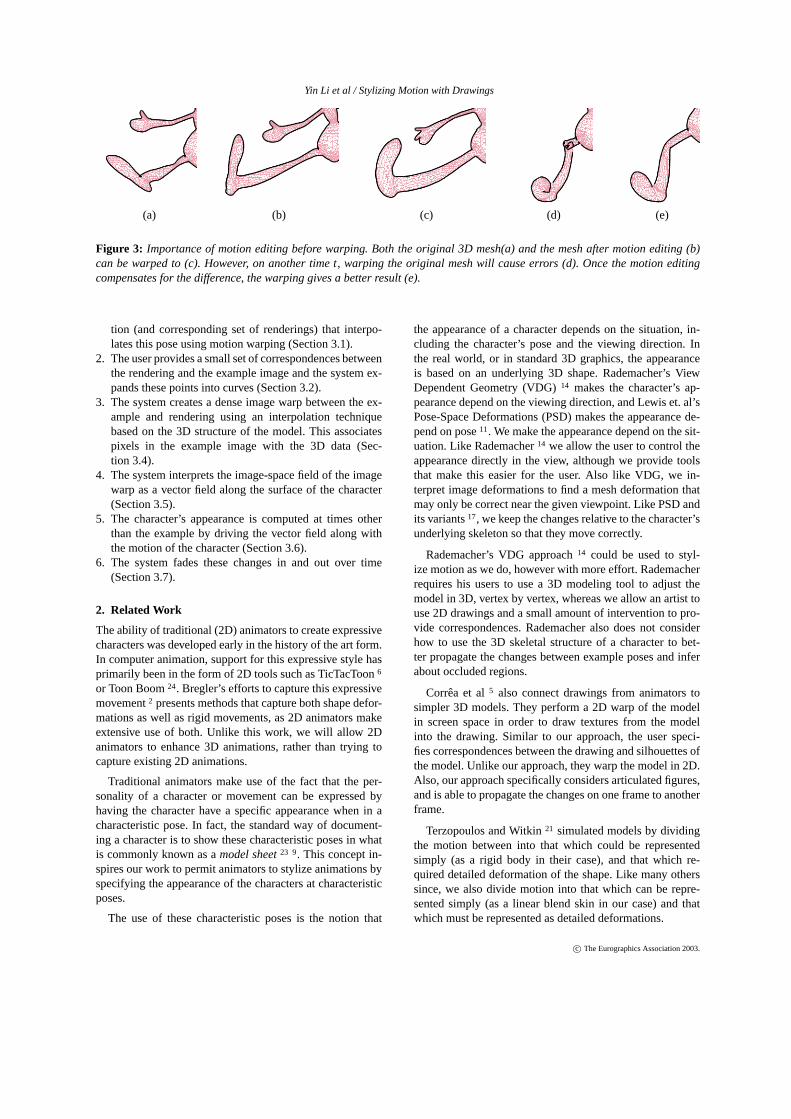
1. The differences between the initial animation and exam-ple sketch can be decomposed into two parts, those thatcan be created by altering the character’s skeletal mo-tion, and those that cannot. This insight allows us to pro-vide the flexibility of arbitrary changes, with the abilityto make large changes in the overall motion. Changes tothe skeletal motion are easier to blend and interpolate,and the image-plane mesh deformations (which have noinformation about depth) are most likely to work best onsmaller disparities (see Figure 3.) It is important to ac-complish as much of the changes with 3D motion editingas possible.
2. The 3D skeletal animation can provide a good model forthe changes that occur in the images. This insight is im-portant since it allows us to devise methods that preservethe discontinuous nature of the image and the 3D motionof the character when working with a 2D image.
3. The 2D deformation field can be viewed as a displace-ment field along the surface of the 3D character, andtherefore propagated by the motion of the character. Thisis important as it provides a way to propagate changesalong the animation.
We call our method for using the 3D skeletal animation in-formation to drive the image deformationsmulti-layer mor-phing, and use it in three different steps in our approach.Such a technique is necessary because a conventional imagemorphing method that does not utilize information about thecharacter would exhibit artifacts where there are nearby oroverlapping parts of the character, and they would not pro-vide any method for using the motion of the 3D character tofind compute other images.
Our approach has the following steps:
1. The user adjusts the skeletal pose that corresponds withthe example image, and the system creates a new mo-
c© The Eurographics Association 2003.
Yin Li et al / Stylizing Motion with Drawings
(a) (b) (c) (d) (e)
Figure 3: Importance of motion editing before warping. Both the original 3D mesh(a) and the mesh after motion editing (b)can be warped to (c). However, on another time t, warping the original mesh will cause errors (d). Once the motion editingcompensates for the difference, the warping gives a better result (e).
tion (and corresponding set of renderings) that interpo-lates this pose using motion warping (Section 3.1).
2. The user provides a small set of correspondences betweenthe rendering and the example image and the system ex-pands these points into curves (Section 3.2).
3. The system creates a dense image warp between the ex-ample and rendering using an interpolation techniquebased on the 3D structure of the model. This associatespixels in the example image with the 3D data (Sec-tion 3.4).
4. The system interprets the image-space field of the imagewarp as a vector field along the surface of the character(Section 3.5).
5. The character’s appearance is computed at times otherthan the example by driving the vector field along withthe motion of the character (Section 3.6).
6. The system fades these changes in and out over time(Section 3.7).
2. Related Work
The ability of traditional (2D) animators to create expressivecharacters was developed early in the history of the art form.In computer animation, support for this expressive style hasprimarily been in the form of 2D tools such as TicTacToon6
or Toon Boom24. Bregler’s efforts to capture this expressivemovement2 presents methods that capture both shape defor-mations as well as rigid movements, as 2D animators makeextensive use of both. Unlike this work, we will allow 2Danimators to enhance 3D animations, rather than trying tocapture existing 2D animations.
Traditional animators make use of the fact that the per-sonality of a character or movement can be expressed byhaving the character have a specific appearance when in acharacteristic pose. In fact, the standard way of document-ing a character is to show these characteristic poses in whatis commonly known as amodel sheet23 9. This concept in-spires our work to permit animators to stylize animations byspecifying the appearance of the characters at characteristicposes.
The use of these characteristic poses is the notion that
the appearance of a character depends on the situation, in-cluding the character’s pose and the viewing direction. Inthe real world, or in standard 3D graphics, the appearanceis based on an underlying 3D shape. Rademacher’s ViewDependent Geometry (VDG)14 makes the character’s ap-pearance depend on the viewing direction, and Lewis et. al’sPose-Space Deformations (PSD) makes the appearance de-pend on pose11. We make the appearance depend on the sit-uation. Like Rademacher14 we allow the user to control theappearance directly in the view, although we provide toolsthat make this easier for the user. Also like VDG, we in-terpret image deformations to find a mesh deformation thatmay only be correct near the given viewpoint. Like PSD andits variants17, we keep the changes relative to the character’sunderlying skeleton so that they move correctly.
Rademacher’s VDG approach14 could be used to styl-ize motion as we do, however with more effort. Rademacherrequires his users to use a 3D modeling tool to adjust themodel in 3D, vertex by vertex, whereas we allow an artist touse 2D drawings and a small amount of intervention to pro-vide correspondences. Rademacher also does not considerhow to use the 3D skeletal structure of a character to bet-ter propagate the changes between example poses and inferabout occluded regions.
Corrêa et al5 also connect drawings from animators tosimpler 3D models. They perform a 2D warp of the modelin screen space in order to draw textures from the modelinto the drawing. Similar to our approach, the user speci-fies correspondences between the drawing and silhouettes ofthe model. Unlike our approach, they warp the model in 2D.Also, our approach specifically considers articulated figures,and is able to propagate the changes on one frame to anotherframe.
Terzopoulos and Witkin21 simulated models by dividingthe motion between into that which could be representedsimply (as a rigid body in their case), and that which re-quired detailed deformation of the shape. Like many otherssince, we also divide motion into that which can be repre-sented simply (as a linear blend skin in our case) and thatwhich must be represented as detailed deformations.
c© The Eurographics Association 2003.

Yin Li et al / Stylizing Motion with Drawings
The problem of interpolating a set of finite controls to pro-duce a continuous field is known as scattered data interpola-tion, and is an important problem for image warping. A sur-vey of the basic issues involved is provided by Wolberg27.Beier and Neely considered using curves as the controls1, al-though we actually treat curve controls as a set of points. Tocreate the interpolation field over points, we use the Multi-level Free Form Deformation technique of Lee et al.10.
Interpolation or warping methods work better when andappropriate model for the field is used. For example, ViewMorphing 16 uses a perspectively correct model to find mo-tion fields that mimic object motions. For our model, we usethe articulated figure motion. Ju and Black8 introduced apixel motion model based on a 2D articulated figure, andBregler and Malik3 provided image flow based on a 3D ar-ticulated model. In both cases, the pixel flow model was usedfor tracking, assumed a completely rigid figure, and did notaccount for significant deviations from the model. Therefore,we create the multi-layed methods of Section 3.4.
Many in the computer vision community have tried to de-termine the shape of 3D objects from silhouettes, or moregeneral line drawings. For example, Terzopoulos et al.22 findthe most symmetric shape that fits a given silhouette, Malikand Maydan discussed recovering shapes from curved sil-houettes12, and Szeliski has presented several methods forfind the shape of the object from multiple silhouettes18, 19.We do not claim that the method we have chosen is eithernovel or superior. It is, however, simple and sufficient forour application.
3. Injecting Style into Animation
As described in Section 1.1 the process begins with a seg-ment of animation created from motion captured data. Suchmotion is stored as a sequence of skeletal poses, where eachpose consists of the position and orientation of the charac-ter’s root, the angles of each of the character’s joints, andthe lengths of each of the segments of the character’s rigidskeleton. We will refer to the initial motion captured data asq0, with an individual pose at timet beingq0(t).
We will use uppercase letters to denote images, withRmeaning an image that was rendered from the 3D charac-ter. ThereforeR0(t) denotes the initial animation, the framesrendered from the initial motion data. We will denote theexample image (drawn by the animator) asX. The exampleimage applies at a specific time in the animation, that we de-note aste, so thatX corresponds toR0(te). For symmetry innotation, we will also refer to the drawn example asX(te) asa reminder of the time at which it applies.
We will denote mappings or fields by Calligraphic letters.For example, a warping fieldWA,B specifies a point in imageB that is associated with each point in imageA. Similarly, adisparity fieldDA,B would specify a vector for each point in
A that leads to its corresponding location inB, or
DA,B(x,y) = WA,B(x,y)− (x,y).
When an example frame is chosen, the user must alsospecify an duration for the example to effect. We call thisduration of time the effective range of the change. The rangeof frames is always centered aroundte and has “radius”∆ sothat the range of frames effected is fromte−∆b to te + ∆a
exclusive. While normally, the example frame is in the cen-ter of the changed duration, we allow for different timingsbefore and after the example.
3.1. Motion Editing
As described in Section 1.1, an initial step in our approach isto edit the skeletal animation such that its approximates theexample image. We refer to the resulting motion asq(t), andthe rendered images created from this motion asR(t). Thetask of motion editing is to chooseq(t) such thatR(te) ≈ X,while making as visually insignificant a change to the motionoverall.
Our motion editing process first determines the pose,q(te), that causes the resulting rendering to be as similar tothe example image as possible. This is done by adjusting theposition of the root, the angles of the joints, the length of theskeletal segments, and the scaling of the geometry in eachof the bones’ coordinate systems. At present, this is doneinteractively by overlaying the example image over the ren-dering and allowing the user to adjust the parameters by acombination of forward and inverse kinematics. An exampleis shown in Figure 4.
While it may be possible to automate the choice ofq(te)by performing an optimization on the residual errorX(te)−R(te), we have chosen not to implement this because theamount of user intervention required to perform this step
Figure 4: Motion editing is performed by overlaying the ex-ample image over the rendered frame (left) and adjustingthe character’s skeletal parameters until the images match(right).
c© The Eurographics Association 2003.

Yin Li et al / Stylizing Motion with Drawings
(given an effective user interface) is quite minimal. Also,existing methods for performing these types of pose opti-mization, such as15 or 3 or 20 would need to be extendedto account for the large amounts of shape deformation thatcannot be accounted for by changing the skeleton.
To createq(t), we use a motion warp26, also known as amotion displacement map4. That is, we compute
q(t) = q0(t)+d(t),
whered(t) is a specially chosendisplacement map.We con-struct d(t) as a pair of cubic Hermite segments, one overtime rangete−∆b to te, and the other fromte to te+∆a. Weset the controls of these splines such that
d(te) = q(te)−q0(te)
d(te−∆) = dte+∆ = 0
and that the first derivative ofd(t) at these three points iszero.
3.2. Correspondence Specification
The motion editing will bring the features of the renderedimage closer to the drawn example. We next need to find awarping field,DR(te),X , that encodes the remaining disparity.We do this as a two step process: first we find correspon-dences between all of the drawn features inX and corre-sponding points inR(te); second, we interpolate these corre-spondences across the entire image plane to achieve a densefield.
The large potential differences betweenX and R(te)makes automatic correspondence difficult. To provide a re-liable method, we allow the user to provide some matchingpoints. User intervention also allows for creative choice infeature matching, as seen in the choice of where the fingeremerges from in Figure 5.
Corresponding the feature curves well may require a largenumber of points, so manual specification is prohibitive.Specifying this large number of corresponding manuallywould be prohibitive, so we provide a semi-automatic ap-proach. We denote correspondence pairi asCi . It consists ofa 2D positionxi in imageX, and a pointri in imageR(te).All of the pointsri must either be vertices of the character’smesh, or points on the edges between two vertices.
Our correspondence approach begins by automaticallycomputing the silhouette and creases of the mesh modelthat is rendered inR(te). These edges are most likely tocreate strong features in the rendering, and, therefore aremost likely to need a correspondence. We detect the silhou-ette from the 3D mesh using the technique introduced byMarkosian et al13. This method produces a long chain ofpoints resulting in a smooth silhouette curve, avoiding thezig-zagging common in simpler approaches. If the mesh is
)(eX)(eR
Figure 5: UI at time te. The user places a few anchor points(highlighted by squares), snapping them on correspondingpositions in the example image. The corresponding curves inbetween these anchors are computed using a snake operator.
not dense, we subdivide mesh to improve the silhouette ap-pearance. To further enhance the quality of the computed sil-houette, we filter the mesh to avoid ruffles, by shrinking thevertex to the average of its neighboring vertices. To com-pensate for volume that is lost by the filtering, we performa re-inflate the character by displacing each vertex along itsoutward-facing normal.
To specify a corresponding pair of curves, the user selectsa few points on the silhouette ofR(te), and specifies the cor-responding locations inX. The system connects the pointsby following silhouette edges in the mesh model to find acurves in the rendering, and applies a snake operator to findan image edge that connect points in the example image, asseen in Figure 5.
3.3. Skinning
Our needs require a pixel flow model that works for morph-ing, handles non-rigid blend-based skinning, and accountsfor significant off-model effects, leading to the developmentof the warping method detailed in this paper. A key idea inour image warping method is to make use of the 3D skinnedmodel that is imaged in the rendering. Therefore, before ex-plaining our method in detail, we review the blend-basedskinning method, sometimes referred to as skeletal subspacedeformation (SSD)11.
Blend-based skinning begins with a model of the charac-ter in what is referred to asdressing pose,and deforms thismodel based on the skeletal pose at a given time. We de-note the positions of vertexj in the dressing pose asvd
j .For each vertex, we specify a skin weight vectorwj whoseentries control how much each bone affects the vertex (e.g.wji specified how much bonei affects vertexj). A resultingvertex position is computed for animation timet by
v j (t) = ∑i
wjiMi(t)vd
j , (1)
c© The Eurographics Association 2003.
Yin Li et al / Stylizing Motion with Drawings
(a) (b) (c) (d)
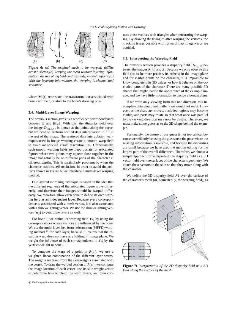
Figure 6: (a) The original mesh to be warped; (b)Theartist’s sketch;(c) Warping the mesh without layering infor-mation: the morphing field confuses independent regions. (d)With the layering information, the warping is cleaner andsmoother.
whereMi(t) represents the transformation associated withbonei at timet, relative to the bone’s dressing pose.
3.4. Multi-Layer Image Warping
The previous section gives us a set of curve correspondencesbetweenX and R(te). With this, the disparity field overthe imageDR(te),X , is known at the points along the curve,but we need to perform scatted data interpolation to fill inthe rest of the image. The scattered data interpolation tech-niques used in image warping create a smooth warp fieldto avoid introducing visual discontinuities. Unfortunately,such smooth warping fields are inappropriate for articulatedfigures where two points may appear close together in theimage but actually be on different parts of the character atdifferent depths. This is particularly problematic when thecharacter exhibits self-occlusion. In order to avoid the arti-facts shown in Figure 6, we introduce a multi-layer warpingmethod.
Our layered morphing technique is based on the idea thatthe different segments of the articulated figure move differ-ently, and therefore their images should be warped differ-ently. We therefore allow each bone to define its own warp-ing field as an independent layer. Because every correspon-dence is associated with a mesh vertex, it is also associatedwith a skin weighting vector. We use the skin weighting vec-tors (w j ) to determine layers as well.
For bonei, we define its warping fieldWi by using thecorrespondences whose vertices are influenced by the bone.We use the multi-layer free form deformation (MFFD) warp-ing method10 for each layer, because it insures that the re-sulting warp does not have any folding in image plane. Weweight the influence of each correspondence toWi by thevertex’s weight in bonei.
To compute the warp of a point inR(te), we use aweighted linear combination of the different layer warps.The weights are taken from the skin weights associated withthe vertex. To draw the warped version ofR(te), we computethe image location of each vertex, use its skin weight vectorto determine how to blend the warp layers, and then con-
nect these vertices with triangles after performing the warp-ing. By drawing the triangles after warping the vertices, thecracking issues possible with forward map image warps areavoided.
3.5. Interpreting the Warping Field
The previous section provides a disparity fieldDR(te),X be-tween the imagesR(te) andX. Because we only observe thisfield (or, to be more precise, its effects) in the image planeand for visible points on the character, it is impossible toknow completely its 3D values, or how it behaves on the oc-cluded parts of the character. There are many possible 3Dshapes that might lead to the appearance of the example im-age, and we have little information to decide amongst them.
If we were only viewing from this one direction, this in-complete data would not matter - we would not see it. How-ever, as the character moves, occluded regions may becomevisible, and parts may rotate so that what once was parallelto the viewing direction may now be visible. Therefore, wemust make some guess as to the 3D shape behind the exam-ple.
Fortunately, the nature of our guess is not too critical be-cause we will only be using the guess near the pose where themissing information is invisible, and because the disparitiesare small because we have used the motion editing for thelargest part of the overall difference. Therefore, we choose asimple approach for interpreting the disparity field as a 3Dvector field over the surfaces of the character’s geometry. Weattach these vectors to the skin so that they move along withthe character.
We define the 3D disparity fieldM over the surface ofthe character’s mesh (or, equivalently, the warping field), as
Figure 7: Interpretation of the 2D disparity field as a 3Dfield along the surface of the mesh.
c© The Eurographics Association 2003.

Yin Li et al / Stylizing Motion with Drawings
attaching to each 3D point a 3D vector that is parallel tothe image plane. These vectors are chosen such that theirprojection is the same as their value in the 2D disparity field,as shown in Figure 7.
The interpreted disparity field provides a 3D model.While this model could potentially be viewed from any di-rection, it will only have the correct appearance in the viewthat the animator specified.
3.6. Warp Field Propagation
The warping field provided by the previous section could befaded in and out to provide a smooth morph between theexample image and the rendered image. This could be donein either the image plane, or in 3D. However, our goal is notto morph between the static images, but instead to integratethe example into the motion of the animation. Whent �= te,we do not want to warp betweenR(t) andX(te). Instead, wemust approximateX(t). Fortunately, since we are only usingX(t) for morphing, its contribution becomes small ast getsfar from te, so it is less important that our approximation ofX(t) is perfect far fromte.
To approximate the example over time, we assume thatthe displacement field is attached to the character in 3D,rather than simply in the image. As the points of the char-acter move, the attached vectors move similarly.
The motion of a vertex on the mesh is given by the skin-ning equation in Equation 1. The transformation for a vertexj from timete to timet is therefore
T j (t) =
(∑i
wjiMi(t)
)(∑i
wjiMi(te)
)−1
. (2)
The motion of the field with respect to the surface that itis attached to is not necessarily given by the attached point.There are two obvious choices: the vector should move alongwith the surface, as the tangent vectors do; or the vectorshould move so that it preserves its relationship with the sur-face, as normal vectors do25. In practice, these two are thesame when the matrices are isotropic (that is only have uni-form scales and no skewing), which the matrices producedby Equation 2 are always at least close to being. We see littledifference between usingTR = (T−1)T or TR = T.
We can compute the disparity field for any point on thecharacter at any time
M(t,v j) = TRj (t)M(te,v j ). (3)
We note that because we have limited information aboutthe appearance of “other sides” of the example, simulatingits motion by simply attaching the morphing field on a 3Dmesh is a crude approximation of what the real motion mightbe except very close tote. In the next section, we will seewhy this is not crucial.
3.7. Assembling the Final Animation
Given the ability to compute the deformation to the characterat any time, we can apply these changes to produce a finalanimation. We define a blending functionα(t) with value 1whent = te, and value 0 whent = te−∆b or t = te+∆a. Theresulting character mesh is therefore
vsi (t) = vi(t)+α(t)M(t,vi).
This equation makes clear that the quality of the warpingfield is only important whent is close tote, asα(t) will besmall otherwise.
If there are multiple example images, each will createits own displacement field and have its own blending func-tion. These additional terms can be added into Equation 3 asneeded.
4. Results
We have implemented the stylization approach by integrat-ing it into two separate systems. Motion editing is done inour character animation testbed, and a separate system han-dles the correspondence, interpretation, and geometry alter-ations. The systems communicate through files. Both sys-tems include stylized renderers that produce the cartoon ren-dering style that we prefer for our experiments and run onpersonal computers. The 2D drawings were created with a2D display tablet and by drawing on paper and scanning.
Many of the examples were created by a professional 2Danimator with no experience with 3D animation, but excel-lent drawing skills. Other examples were created by com-puter scientists. The task of creating drawings is not too dif-ficult for the untrained artists as the original rendering canbe used as a guide for tracing.
The dancing ant animation in Figures 1 and 2 was createdby applying a standard library motion to a standard librarycharacter (both available freely on the web), using a motionretreating technique7. We took a short loop of dancing mo-tion and showed it to a professional animator who redrewtwo frames. Figure 8 shows a character from a commercialdatabase applied to a different stock motion and stylized.
Figure 8: Another example of our system. From left to right:Original frame, the sketch, the result frame, another framepropagated.
c© The Eurographics Association 2003.
Yin Li et al / Stylizing Motion with Drawings
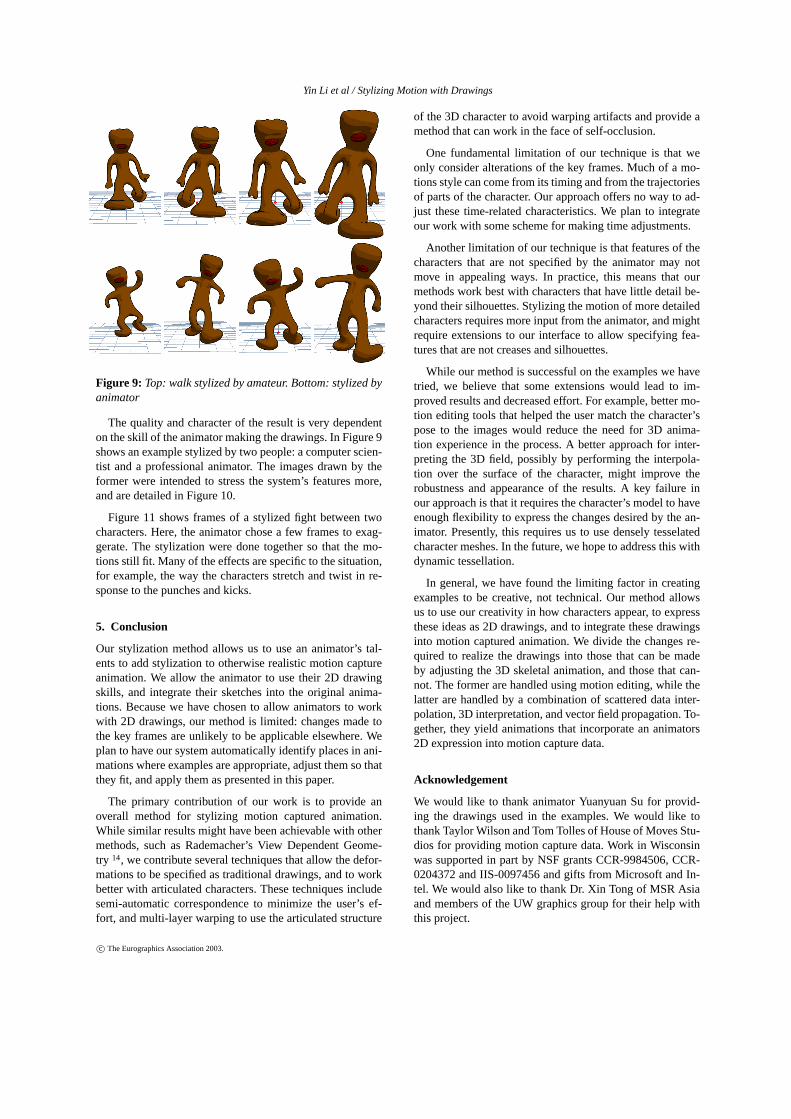
Figure 9: Top: walk stylized by amateur. Bottom: stylized byanimator
The quality and character of the result is very dependenton the skill of the animator making the drawings. In Figure 9shows an example stylized by two people: a computer scien-tist and a professional animator. The images drawn by theformer were intended to stress the system’s features more,and are detailed in Figure 10.
Figure 11 shows frames of a stylized fight between twocharacters. Here, the animator chose a few frames to exag-gerate. The stylization were done together so that the mo-tions still fit. Many of the effects are specific to the situation,for example, the way the characters stretch and twist in re-sponse to the punches and kicks.
5. Conclusion
Our stylization method allows us to use an animator’s tal-ents to add stylization to otherwise realistic motion captureanimation. We allow the animator to use their 2D drawingskills, and integrate their sketches into the original anima-tions. Because we have chosen to allow animators to workwith 2D drawings, our method is limited: changes made tothe key frames are unlikely to be applicable elsewhere. Weplan to have our system automatically identify places in ani-mations where examples are appropriate, adjust them so thatthey fit, and apply them as presented in this paper.
The primary contribution of our work is to provide anoverall method for stylizing motion captured animation.While similar results might have been achievable with othermethods, such as Rademacher’s View Dependent Geome-try 14, we contribute several techniques that allow the defor-mations to be specified as traditional drawings, and to workbetter with articulated characters. These techniques includesemi-automatic correspondence to minimize the user’s ef-fort, and multi-layer warping to use the articulated structure
of the 3D character to avoid warping artifacts and provide amethod that can work in the face of self-occlusion.
One fundamental limitation of our technique is that weonly consider alterations of the key frames. Much of a mo-tions style can come from its timing and from the trajectoriesof parts of the character. Our approach offers no way to ad-just these time-related characteristics. We plan to integrateour work with some scheme for making time adjustments.
Another limitation of our technique is that features of thecharacters that are not specified by the animator may notmove in appealing ways. In practice, this means that ourmethods work best with characters that have little detail be-yond their silhouettes. Stylizing the motion of more detailedcharacters requires more input from the animator, and mightrequire extensions to our interface to allow specifying fea-tures that are not creases and silhouettes.
While our method is successful on the examples we havetried, we believe that some extensions would lead to im-proved results and decreased effort. For example, better mo-tion editing tools that helped the user match the character’spose to the images would reduce the need for 3D anima-tion experience in the process. A better approach for inter-preting the 3D field, possibly by performing the interpola-tion over the surface of the character, might improve therobustness and appearance of the results. A key failure inour approach is that it requires the character’s model to haveenough flexibility to express the changes desired by the an-imator. Presently, this requires us to use densely tesselatedcharacter meshes. In the future, we hope to address this withdynamic tessellation.
In general, we have found the limiting factor in creatingexamples to be creative, not technical. Our method allowsus to use our creativity in how characters appear, to expressthese ideas as 2D drawings, and to integrate these drawingsinto motion captured animation. We divide the changes re-quired to realize the drawings into those that can be madeby adjusting the 3D skeletal animation, and those that can-not. The former are handled using motion editing, while thelatter are handled by a combination of scattered data inter-polation, 3D interpretation, and vector field propagation. To-gether, they yield animations that incorporate an animators2D expression into motion capture data.
Acknowledgement
We would like to thank animator Yuanyuan Su for provid-ing the drawings used in the examples. We would like tothank Taylor Wilson and Tom Tolles of House of Moves Stu-dios for providing motion capture data. Work in Wisconsinwas supported in part by NSF grants CCR-9984506, CCR-0204372 and IIS-0097456 and gifts from Microsoft and In-tel. We would also like to thank Dr. Xin Tong of MSR Asiaand members of the UW graphics group for their help withthis project.
c© The Eurographics Association 2003.

Yin Li et al / Stylizing Motion with Drawings
References
1. Thaddeus Beier and Shawn Neely. Feature-based im-age metamorphosis. InComputer Graphics (Proceed-ings of SIGGRAPH 92), volume 26, pages 35–42, July1992.
2. Christoph Bregler, Lorie Loeb, Erika Chuang, andHrishi Deshpande. Turning to the masters: Motioncapturing cartoons.ACM Transactions on Graphics,21(3):399–407, July 2002.
3. Christoph Bregler and Jitendra Malik. Tracking peoplewith twists and exponential maps. InProc. IEEE Conf.Comp. Vision and Pattern Recognition, 1998.
4. Armin Bruderlin and Lance Williams. Motion signalprocessing. InProceedings of SIGGRAPH 95, pages97–104, August 1995.
5. Wagner Toledo Corrêa, Robert J. Jensen, Craig E.Thayer, and Adam Finkelstein. Texture mapping forcel animation. InProceedings of SIGGRAPH 98, Com-puter Graphics Proceedings, Annual Conference Series,pages 435–446, July 1998.
6. Jean-Daniel Fekete, Érick Bizouarn, Éric Cournarie,Thierry Galas, and Frédéric Taillefer. Tictactoon: A pa-perless system for professional 2-d animation. InPro-ceedings of SIGGRAPH 95, pages 79–90, August 1995.
7. Michael Gleicher. Retargeting motion to new charac-ters. In Michael Cohen, editor,SIGGRAPH 98 Confer-ence Proceedings, pages 33–42. Addison Wesley, July1998.
8. S. X. Ju, M. J. Black, and Y. Yacoob. Cardboardpeople: A parameterized model of articulated motion.In 2nd Int. Conf. on Automatic Face- and Gesture-Recognition, pages 38–44, Killington, Vermont, Oct1996.
9. Larry Lauria. Larry’s toon institute: Character modelsheets. web page, 1999.
10. Seung-Yong Lee, Kyung-Yong Chwa, and Sung YongShin. Image metamorphosis using snakes and free-formdeformations.Computer Graphics, 29:439–448, 1995.
11. J. P. Lewis, Matt Cordner, and Nickson Fong. Posespace deformations: A unified approach to shape inter-polation and skeleton-driven deformation. InProceed-ings of ACM SIGGRAPH 2000, pages 165–172, July2000.
12. Jitendra Malik and Dror Maydan. Recovering three di-mensional shape from a single image of curved objects.IEEE Trans on PAMI, 11(6):555–566, June 1989. 1989.
13. Lee Markosian, Michael A. Kowalski, Samuel J.Trychin, Lubomir D. Bourdev, Daniel Goldstein, andJohn F. Hughes. Real-time nonphotorealistic render-
ing. In Proceedings of SIGGRAPH 97, pages 415–420,August 1997.
14. Paul Rademacher. View-dependent geometry. InPro-ceedings of SIGGRAPH 99, pages 439–446, August1999.
15. J. Rehg and T. Kanade. Model-based tracking of self-occluding articulated objects. InProc. 1995 IEEE IntlConf. on Computer Vision, Cambridge, MA, 1995.
16. Steven M. Seitz and Charles R. Dyer. View mor-phing: Synthesizing 3d metamorphoses using imagetransforms. InProceedings of SIGGRAPH 96, pages21–30, August 1996.
17. Peter-Pike J. Sloan, III Charles F. Rose, and Michael F.Cohen. Shape by example. InProceedings of the 2001symposium on Interactive 3D graphics, pages 135–143,2001.
18. Richard Szeliski. Rapid octree construction from imagesequences.CVGIP: Image Understanding, 58(1):23–32, 1993.
19. Richard Szeliski and Richard Weiss. Robust shaperecovery from occluding contours using a linearsmoother.Intl Journal of Computer Vision, 28(1):1998,1998.
20. Camillo J. Taylor. Reconstruction of articulated objectsfrom point correspondences in a single image. InInIEEE CVPR, June 2000.
21. Demetri Terzopoulos and Andew Witkin. Physically-based roodels with rigid and deformable components.IEEE CG&A, 8(6):41–51, November 1988.
22. Demetri Terzopoulos, Andrew Witkin, and MichaelKass. Symmetry-seeking models and 3d object recon-struction. Intl Journal of Computer Vision, 1(3):211–221, 1987.
23. Frank Thomas and Olliver Johnson.Disney Animation:The Illusion of Life. Abbeville Press, 1984.
24. Toon Boom Technologies. Toon boom studio. Com-puter Software, 2002.
25. Kenneth Turkowski. Transformations of surface normalvectors. Technical Report 22, Apple Computer, July1990.
26. Andrew P. Witkin and Zoran Popovic. Motion warp-ing. In Proceedings of SIGGRAPH 95, pages 105–108,August 1995.
27. George Wolberg.Digital Image Warping. IEEE Press,1990.
c© The Eurographics Association 2003.

Yin Li et al / Stylizing Motion with Drawings
a) b) c) d)
Figure 10: Editing a walking motion (a) original frame (b) sketch, (c) motion editing only (d) final frame
Figure 11: A fight between two characters is stylized.
c© The Eurographics Association 2003.