Embed Size (px)
Citation preview

Study of Composite Pressure Vessel using Workbench and
APDL
Andrés Liberatto
Eduardo Araujo
PRESENTATION TOPICS
• Motivation
• Geometry – simplification
• Modeling
– Choice of elements
– Meshing Strategy
– Lay-up Definition and Element Orientation
– Boundary Conditions
• Post Processing

• This study was performed with the company CENIC and present the
modeling sequence of a typical pressure vessel fabricated with filament
winding process.
• Geometry, data material were provided by CENIC.
• To use the resources available in Ansys 14.0 Workbench and APDL
Motivation

CENIC

– Step geometry file was provided
– Ansys imports step file
Geometry

• Some components were neglected for this study
– Fasteners
– Anchoring Holes
– Coupling Rings
– O-rings
• All other components were divided (cut) to allow the user to use good
meshing strategy.
– To divide by 4 parts in longitudinal directon
– To divide by 3 parts in transversal direction
• Sweep mesh. At least 2 elements through thickness
– Only brick element. Transition elements are wedges.
Geometry - simplification

• Why should one use bricks?
• Composites (laminated) elements demand
controlled mesh and brick solid elements.
Geometry - simplification

Geometry – after simplification

Modeling- Element Choice

• Ansys 14.0
• Standard resources of Workbench plus APDL
Modeling – Meshing strategy

• Brick and wedge element mesh
– Swept mesh (revolution) around main cylinder axis
– Two elements through thickness to guarantee quality of results
– Named_Selection were used to define the mesh generation regions (vide
images)
– Lay-up is divide by 2 (half for each element)
– Important: laminate thickness will be correct even if there is thickness variation
(domes region). Thickness distribution of layers is proportional to the specified
lay-up.
Modeling – Meshing strategy

Mesh

Mesh – External Cover

Mesh – filament winding vessel

Mesh – Metallic Vessel

Mesh – Metallic Vessel
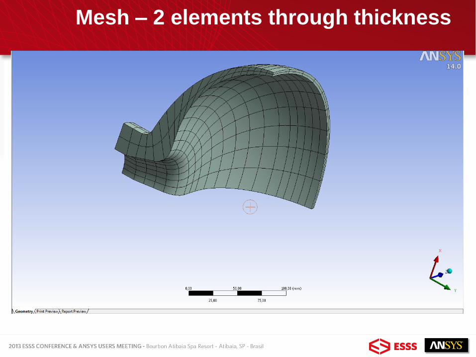
Mesh – 2 elements through thickness

Named Selections Regions

Named Selections Regions

Named Selections Regions

Named Selections Regions

Named Selections Regions

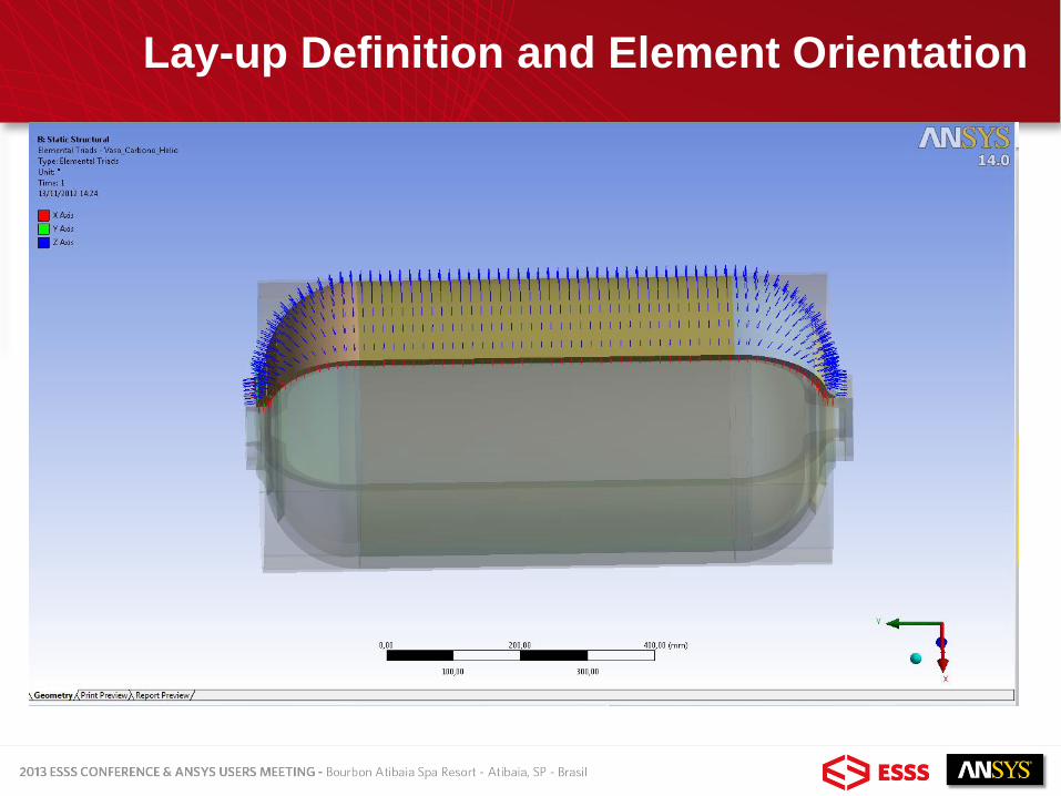
• APDL (Ansys Parametric Design Language) Commands were used to
define lay-up and Element Orientation
• Domes were divide in 3 transversal parts to accomodate orientation
changes with the capabilities available.
• Ansys Workbench and APDL commands were used to model the pressure
vessel in this presentation . The job would be much easier and simplified
with ACP (Ansys Composite Pre-Post) .
Lay-up Definition and Element Orientation
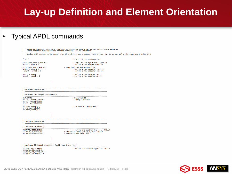
• Typical APDL commands
Lay-up Definition and Element Orientation
Lay-up Definition and Element Orientation

Lay-up Definition and Element Orientation

Lay-up Definition and Element Orientation

Boundary Condition
Fixed Support

Boundary Condition
Pressure

Boundary Condition
Pressure (internal)

Typical Results
Displacements

von Mises stress (metal)
Typical Results

Typical Results
Von Mises Stress (Metal)

Typical Results
• Results visualization in the layers is done using
APDL commands
Typical APDL
commands

Typical Results
Tensão Equivalente Von Mises

Typical Results

Typical Results

Typical Results

Typical Results

Typical Results

Typical Results

Typical Results

Typical Results

Typical Results

Typical Results

OBRIGADO!!
THANK YOU