Embed Size (px)
Citation preview

Department of Mechanical and Aerospace EngineeringRutgers University
Piscataway, New Jersey 08854
PRESSURE VESSEL DESIGN USING COMPOSITE MATERIALS
GROUP 2Graig Fergusson
David Pons
Ronnie Nomeir
Danielle Stephens
Russell Scola
1

Index
Index . . . . . . . . . 2
Introduction . . . . . . . . 3
Geometry and Design Constraints . . . . 6
Composite Material Design . . . . . 8
Preliminary Designs . . . . . . 13
Final Design . . . . . . . . 14
Materials . . . . . . . . . 15
Dimensions . . . . . . . . 18
Construction Procedure . . . . . . . 19
Design Changes . . . . . . . . 21
Testing . . . . . . . . . 24
Original Design Goal . . . . . . . 26
Future Plans . . . . . . . . 27
2

Introduction
Composite materials are widely used in industry and engineering processes today
due to their many applications and advantages. A composite material is defined as a
combination of two or more materials consisting of different properties. This union
essentially creates a new material with properties that are unique from the beginning
components. Although they are joined together, a visible separation between the
individual materials is still present.
The material utilized for this design project is carbon fibers in an epoxy matrix. It
will be implemented using lamina sheets of the material. When dealing with composites,
the term “matrix” is used to describe the material that surrounds and binds together
clusters of the stronger material which, in this case, is the epoxy. The carbon fiber is
known as the “reinforcement” material. When examined separately, carbon fiber and
epoxy are quite different materials when their individual properties are viewed. The
carbon fiber is made out of long, thin sheets of carbon. It is a chemically inert rigid
material that is difficult to stretch and compress. On the other hand, epoxy is a
thermosetting plastic, or resin, that is liquid when prepared but hardens and becomes
rigid (i.e., it cures) when is heated. The setting process is irreversible, so that it does not
become soft again under high temperatures. Epoxy plastics are good at resisting wear
and are highly durable when exposed to extreme environments.
3

The combination of these two materials into a composite has many advantages.
Along with holding the fibers together, the matrix is advantageous since it protects the
carbon fiber from damage by sharing any stress incurred in the element. It also provides
flexibility to the otherwise rigid material which aides in shaping and molding.
Composites are more versatile than metals and can be tailored to meet performance needs
and complex designs. As a whole, the composite has a very high specific strength, which
means it has a very high strength and low weight. In many cases, the composite is lighter
than traditional materials for certain applications with comparable strength. The joining
of the materials provides excellent fatigue endurance concerning the number of load
cycles and residual fatigue strength that is many times higher than that of metals. In
addition, the composite has good resistance against, chemicals, acids, water, and varying
elements. There is very little corrosion which leads to low maintenance costs over long
periods of time.
The downside of composites is usually the cost. Although manufacturing
processes are often more efficient when composites are used, the raw materials are
expensive. Also, epoxy resins are more expensive than polyester resins and vinyl ester
resins, but generally produce stronger more temperature resistant composite parts.
Another usage concern is regarding the material’s life-cycle. Since carbon fiber
4

reinforced plastics have an almost infinite lifetime, companies need to find means in
which to recycle the material. The high amount of (often manual) work required to
manufacture composites has limited their use in applications where a high number of
complicated parts is required. Composites will never totally replace traditional materials
like steel, but in many cases they are very useful.
Carbon-epoxy materials are finding increased structural uses in areas such as
aerospace, structural engineering, automotive, and sporting goods applications. It excels
at replacing conventional materials in objects ranging from space shuttle components,
bridge reinforcements, car body parts, and basketball backboards just to name a few.
Furthermore, as technology evolves, new uses will be found.
The primary goal of this design project is to use the knowledge gained about
composites and their advantages to create a carbon fiber / epoxy pressure vessel. The
materials utilized in this project will consist of carbon / graphite fibers acting as
reinforcement in an epoxy matrix formed in several layers or lamina. These materials are
usually flexible, and can be molded into almost any desired shape; in this case they will
5

be molded into a cylinder and then baked in a kiln or high pressure oven until both
materials mesh together and become a single hard structure. In order to complete this
goal, a $400 budget will be used to acquire all the materials needed for design.
Geometry and Design constraints
A pressure vessel is a container designed to operate at pressures typically over 15
P.S.I.G. The design of a pressure vessel is entirely reliant upon mechanics of materials.
Prediction of the ultimate strength of a designed vessel is done using various failure
theories. When building a pressure vessel out of composite materials, some the theories
employed to optimize strength and predict failure are the Tsia – Hill energy-based
interaction theory, and maximum stress and strain theory. The forces at applied in the
different directions of the pressure vessel are directly related to the magnitude of the
pressure and are given below.
The stress in the circumferential or hoop direction is given by equation 1.
[1. Hoop Stress]
The stress acting in the axial direction is given by equation 2.
[2. Axial Stress]
The stress acting on the hemispherical ends is given by equation 3.
[3. Hemispherical Ends]
6

When comparing the stresses at each location, it is clear from the above equations that the
hoop stress is twice as much as the stress in the hemispherical ends and axial direction.
This is a big consideration when constructing the design and geometry of pressure vessel.
The geometry of the pressure vessel is also a very important parameter. For
practicality issues a conventional pressure vessel shape is ideal. A pressure vessel used
for nitrous oxide is shown in figure 1 below. This design is effective for conserving
space and is moderately strong. Unlike the pressure vessels in figure 1, the designed
vessel will not have any sharp geometry. If strength is the sole concern, the ideal
geometry would be a sphere. This would virtually eliminate stress being concentrated in
one area, such as what occurs with sharp geometry. In order to compromise between
strength and size practicality, the designed pressure vessel employs a cylindrical body
with curved end caps. The curved end caps provide a smooth transition minimizing
stress concentrations.
Due to the potential health hazard involved with high pressure vessels, safety is a
very important design consideration. If cracking occurs while the pressure vessel is in
service blasting effects can occur due to the sudden effects of the expanding gas. There
7
Fig 1

can also be fragmentation damage and injury if the vessel completely ruptures. If leakage
occurs the results can also be severe. Depending on what is contained in the pressure
vessel poisoning or suffocation can occur. In order to reduce chances of these hazards a
safety factor of at least two is typically employed. Industrial pressure vessels are used in
the United States are usually built to one of two pressure vessel design codes. The first
being the ASME (American Society of Mechanical Engineers), the second is the API
Standard 620, or the American Petroleum Institute code. This provides guidelines for
lower pressure vessels that are not covered by the ASME code.
Pressure vessels used in industry are typically constructed of metals due to their
high strength and ease of machining. Metals can be formed into virtually any shape,
making it possible to construct the most effective geometries.
Composite Material Design
On normal isotropic materials, it is sufficient to describe their mechanical properties
using just two engineering constants. Usually the Young’s Modulus and the Poisson’s
ratio. However, on anisotropic materials, much more is required to fully describe the
material’s behavior. An anisotropic material is a material that its properties at a specified
point vary with direction or depend on the orientation of reference axes. For example the
material’s Young’s Modulus in the x-direction might not be the same than in the y-
direction. For this reason the engineering mechanics of composite materials are a lot
more complex to study than isotropic materials and most of the isotropic equations do not
apply to composite materials and must be modified to study such behavior.
8

In order to fully describe anisotropic materials, more engineering constants are
required. In the case of thin lamina where it is assumed to be under a state of 2-
dimensional plane stress, the engineering constants E1, E2, G12 and ν12 are necessary to
describe the composite material’s properties. E1 and E2 represent the Young’s Modulus in
the 1-direction and 2-direction respectively, G12 represents the shear modulus in the 1-2
plane and ν12 represents the Poisson’s ratio from 1-2. A unidirectional lamina
representation is shown in the following figure. All of the properties described above
hold true in their respective direction, for example, E1 is only applicable in the 1-direction
or along the direction of the fibers. Some numerical manipulation must be performed in
order to relate the properties to the corresponding x or y axis.
Following there are the basic equations that are used in the design of process of
composite materials.
If we define a matrix T as :
Then the following equations can be used to relate the mechanical properties and the
stress and strain relations with their respective axis:
9

éêêêêë
s xs yt s
ùúúúúû
=
éêêêêë
Qxx Qxy Qxs
Qyx Qyy Qys
Qsx Qsy Qss
ùúúúúû
éêêêêë
3x3ygs
ùúúúúû
éêêêêë
3x3ygs
ùúúúúû
=
éêêêêë
Sxx Sxy Sxs
Syx Syy Sys
Ssx Ssy Sss
ùúúúúû
éêêêêë
s xs yt s
ùúúúúû
Where:
éêêêêë
Sxx Sxy Sxs
Syx Syy Sys
Ssx Ssy Sss
ùúúúúû
= inv
æççççè
éêêêêë
Qxx Qxy Qxs
Qyx Qyy Qys
Qsx Qsy Qss
ùúúúúû
ö÷÷÷÷ø
m = cos (q) and n = sin (q)
Qxx = m4Q11 C n4Q22 C 2 m2n2Q12 C 4 m2n2Q
Qyy = n4Q11 C m4Q22 C 2 m2n2Q12 C 4 m2n2Q
Qxy = m2n2Q11 C m2n2Q22 C 0m4 C n41Q12 K 4 m2n2Q66
Qxs = m3nQ11 K mn3Q22 K mn0m2K n21Q12 K 2mn
(m2K n2 ) Q66
Qys = mn3Q11 K m3nQ22 C mn0m2K n21Q12 C 2mn (m2K n2 ) Q66
Qss = m2n2Q11 K m2n2Q22 K 2 m2n2Q12 C (m2K n2 )2Q
10

And
Q11 = E11 K y12y21
Q22 = E21 K y12y21
Q12 = Q21 = y21E1
1K y12y21=
y12E21K y12y21 Q66 = G12
Also:
Sxx = m4S11 C n4S22 C 2 m2n2S12 C 4 m2n2S
Syy = n4S11 C m4S22 C 2 m2n2S12 C 4 m2n2S
Sxy = m2n2S11 C m2n2S22 C 0m4 C n41S12 K 4 m2n2S
Sxs = m3nS11 K mn3S22 K mn0m2 K n21S12 K 2mn
(m2 K n2 ) S66
Sys = mn3S11 K m3nS22 C mn0m2K n21S12 C 2mn (m2K n2 ) S66
Sss = m2n2S11 K m2n2S22 K 2 m2n2S12 C (m2 K n2 )2S
Where
S11 = 1 E1
S22 = 1 E2
11

S12 = S21 = Ky12E1
= Ky21E2
S66 = 1 G12
With these equations it is now possible to study the mechanics of composite
materials using traditional, isotropic material equations. In pressure vessel design, it is
important to find the optimal angle of fiber orientation that will reduce the stress along
the principal axes (1, 2). This can be achieved with some manipulation of the equations
above.
The maximum stress must never become equal or greater than the failure stress of
the material in its respective axis. In order to ensure safety so that we are able to test the
pressure vessel, three different strength theories were employed in this design to make
certain that this condition does not occur. After relating the pressure inside the vessel
with the stress and strain acting on the lamina, the value for the stress is compared to the
maximum stress allowable before the material fails. This stress is denoted the Ultimate
stress or the Failure stress.
The first strength theory used in the design was the Maximum Stress theory. This
theory basically ensures that the stress in either the 1 or 2 direction will never exceed the
Failure Stress in its respective direction. This theory is expressed in the simple following
equation:
The design will fail if:
s1 R F1 or s2 R F2 or t6 R F
12

This equation is very useful and simple to employ in the design. The next
equation used ensures that the maximum strain will not be reach the ultimate strain. This
theory is called the Maximum Strain Theory is expressed in the following equations.
The design will fail if:
s1 K y12s2 R F1 or s2 K y21s1 R F2 or r t6 r R F
These equations are very simple and in most cases work very well; however, they
does not take into account the interaction between these stresses and the strains acting
together in the design. For that reason, the Energy Based Interaction Theory (Tsai-Hill) is
used.
The design will fail if:
13

s12
F12
C s2
2
F22
C t6
2
F62 K
s1s2F1
2 R 1
It is then with the application of these three different strength theories that we are
able to ensure that the design being developed is safe and should provide us with the
confidence that it will perform as required.
Design Options
The preliminary designs for the pressure vessel to be constructed from the carbon
fiber epoxy material were narrowed down to the five that showed the most potential.
One of the first proposed designs was to construct the pressure vessel in one piece
with no end caps. The benefit of this design would be higher strength due to its single
piece construction. However, the manufacturing process of this design has practicality
issues. In order to get the correct shape a mould would have to be constructed. The
lamina sheets would then be wrapped around the mold and baked. Therefore, the
problem with this design is removing the mold from the finished product.
The final design a previous group used consisted of a cylindrical tube for the
vessel body and plastic end caps. Due to the end caps being made out of plastic they
were much weaker then the carbon fiber epoxy body. The result of using the plastic end
caps is that when pressure is sufficiently high they crack. Also, since these end caps are
glued on, failure occurs since the strength is weaker at these points. The final design
chosen by this group is therefore to construct a cylindrical body, as well as end caps out
of the carbon fiber epoxy material. The difficulty results in designing the end caps. The
strongest design is a circular one, which is difficult when working with lamina sheets.
The lamina sheets resemble a stiff fabric, and forming them into a curved surface would
14

be difficult. The final design for these end caps is therefore to use thin strips of the
material overlapping each other and angled offset from each other. The result is expected
to resemble the figure below.
Once there end caps are made, they are then attached to the main cylindrical body.
The cylindrical body is the easiest to produce during the manufacturing process, since the
thin composite sheets, being the shape of paper, are easy to mold into a cylinder. In this
project, and final design, we will be using 6 layers of the composites. This will come into
play when finding the correct fiber orientation between lamina, since when transforming
the stresses in the x and y axes to the 1 and 2 axes like in the above figures, must be done
for each layer.
Unidirectional Carbon Fiber Cloth
Unidirectional Carbon fiber cloth will be purchased from Jamestown Distributors in
Rhode Island. It is sold by the yard and the majority to be purchased will have a width of
15

12.5’’. One yard of 50 inch width cloth will also be purchased to allow 0o – 90o
orientation of layers at the end caps. It is estimated that to construct one vessel with the
planned dimensions six yards of cloth will be necessary. Two vessels will be constructed
and in order to ensure ample supply of carbon cloth 14 yards of the 12.5 inch width cloth
will be purchased.
Valve Connection
In order to make the connection between the valve and the pressure vessel, a valve
connector will be machined out of carbon steel. The carbon fiber cloth will be wrapped
around this part during the construction procedure. The valve connector is shown in
figure 1.
Figure 1. Valve Connector
The valve connector will have a large radius of .5’’, a small radius of .25’’, an
inner diameter of .312’’, and a length of 2.5’’. This part will be machined from 1018
carbon steel starting from rods with a 2’’ diameter and 3’’ length. It will be purchased
from McMaster.
VALVE
16

The valve will also be purchased from McMaster. The one selected is a high pressure
needle valve with a .5'' pipe, 2.75’’ length and orifice diameter of .312’’. The selected
valve is rated for pressures of up to 10000 Psi. A picture of the valve is shown in figure
2.
Figure 2. High Pressure Needle Valve.
EPOXY
As is shown later in the construction procedure of this report, the first layer of
carbon fiber cloth will be cured with epoxy. This will create an impermeable layer which
will allow testing with water if necessary. One quart of West System 105 epoxy resin
will be used as well as .44 pints of 206 West System hardener. The hardener will allow
curing at room temperature. To ensure the correct mixing ratios are used a mini pump set
made to dispense the correct ratios of hardener and epoxy will also be purchased.
GEOPOLYMER RESIN
Aside from the first layer, all layers of carbon fiber cloth will be cured with
Geopolymer resin. Unlike the epoxy, Geopolymer is an inorganic polymer matrix that is
resistant to temperatures of up to 1000o C. It consists of an Alumina Silicate solution and
17

can be cured at room temperature. Organic polymer resins such as the epoxy to be used
for the first layer soften and ignite at temperatures between 200oC and 600oC. However,
when compared to the epoxy, the Geopolymer is water permeable and has poor strain
compensation. This is why the first layer will be cured with epoxy.
TOTAL COST AND MATERIALS
Jamestown Distributors
Component Price
Amount
Needed Subtotal
Carbon Fiber Cloth 12.5 inch wide (cost/yard) $11.01 14.00 $154.14
Carbon Fiber Cloth 50 inch wide (cost/yard) $26.23 1.00 $26.23
1 Qt. West System 105 Epoxy Resin $29.80 1.00 $29.80
.44 Pint West System 206 Resin $13.90 1.00 $13.90
Epoxy Resin and Hardener Mini Pump Set $10.35 1.00 $10.35
McMaster
Carbon Steel Rods 2'' diameter 3'' length $8.75 5.00 $43.75
.5'' pipe, 2.75'' length High Pressure Needle Valve $46.35 2.00 $92.70
Civil Engineering Department
Geopolymer Resin $0.00
Clay $0.00 Total $370.87
Table 1. Materials and costs
PRESSURE VESSEL DIMENSIONS
The pressure vessel will be constructed around a clay mold with the following
dimensions. It will have a cylindrical body which is six inches in diameter and 8 inches
long. It will have spherical end caps with three inch radii, which will make the entire
mold 14 inches long. Carbon fiber cloth with a thickness of .027 and .033 inches will be
18

used, making the minimum thickness of the vessel .162 inches. Overlapping of the cloth
at the end caps will add an additional 1.44 inches to each end. This will make the total
length of the vessel 16.88 inches. Figure 3 below shows the dimension of the mold
which the vessel will be constructed around.
Figure 3. Mold dimensions
CONSTRUCTION PROCESS
The first step in the
construction process will
be to construct a clay
mold. A valve connector
19

will then be placed on the clay mold in the center of each spherical end cap. Once this is
done the carbon fiber cloth which will be used is sold with a width of 12.5 inches and 50
inches will be cut into strips that are 8 and 1.5 inches wide. The cloth will be coated with
epoxy and wrapped around the mold length wise, passing over each valve connector and
completing one layer. The first will be done with epoxy to create a water impermeable
layer, which will allow more testing options and make it possible to use clay when
dissolving the mold. This is shown in figure 4 below.
Figure 4. stage 1 of construction sequence .
The second layer will consist of two stages, the first being to
wrap an 8 inch width cloth
around only the cylindrical
body. From this stage
forward all the carbon fiber
strips will be wetted with
Geopolymer resin. This
stage is shown in figure 3
below.
20

Figure 3, stage 2 of construction sequence
stage 2 (Geopolymer Resin).
`The second stage will be to wrap 1.5 inch wide strips wetted with Geopolymer resin
around the end caps and 2 inches of the cylindrical body. The strips will extend 2 inches
into the cylindrical body to strengthen the interface between the cylindrical body and the
end caps. This is shown in figure 4 below.
Figure 4, stage 3 of
construction sequence.
21

Each time this construction sequence is completed 2 layers of the carbon fiber are added
to the vessel. Although the construction sequence shown above has a valve connector at
only one end, one will built into both ends. This will allow the installation of 2 valves,
giving better circulation when removing the clay. The clay mold will also be constructed
around a quarter inch diameter rod protruding through each valve connector. When the
first layer, which will be water impermeable, is complete the rod will be removed and
water will be circulated through the vessel via the valve connectors at each end. The
water will dissolve the clay and leave the first layer. The second and third stages of the
construction sequence will then be completed creating a total of 2 layers. The
construction sequence will then be repeated using only Geopolymer resin for the
remaining 4 layers.
Design Changes
The first design change was the construction of the mold. Instead of using clay as
was proposed earlier the mold was constructed using brown sugar. The brown sugar was
placed in a container with the desired shape and allowed to harden. The design change
was made in order to ensure easy removal of the mold once the first layer of carbon –
fiber epoxy was completed. When compared to clay the brown sugar dissolve much
easier in water and was very hard when dry, making it easy to wrap the carbon – fiber
strips around.
The second design change was the valve connector. Instead of machining the
whole component from one piece of carbon steel, a tapered .5 inch diameter, 3 inch long
plumbing nipple, (double threaded short pipe), was used. A circular disk with a 1.4 inch
diameter was machined from the carbon steel, and threaded to fit the plumbing nipple.
22

To ensure strength the disk was welded to the nipple. Figure 5 shows the completed
valve connector.
Figure 5. Completed valve connector.
The third design change was the construction process. Instead of wetting the first
layer of carbon – fiber cloth with epoxy and the remaining 5 layers with Geopolymer
resin, all six layers were wetted with epoxy. The final layer was wetted with epoxy only
on the side in contact with the mold and then painted with a Geopolymer – Glass/Carbon
Fiber mixture. This change was made to increase the strength of the vessel. Since the
Geopolymer adds no tensile strength to the carbon fiber and is very brittle cracking would
occur. The epoxy was used to ensure added tensile strength and better strain capabilities.
Instead of using the needle valve mentioned above, a ball valve was used. The
ball valve is rated for 500 psi as opposed to 10,000 when compared to the needle valve.
This change was made because the needle valve was very difficult to work with.
COMPLETED VESSEL
Figures 6 and 7 show the completed pressure vessel before the Geopolymer was added to
the last layer. Figure 8 shows the pressure vessel painted with the Geopolymer resin.
23

Figure 6
Figure 7
24

Figure 8
TESTING
The testing was done to 100 psi with air using an air compressor. The pressure vessel
was put under a wheel barrow, which was weighed down with cinder blocks. The
pressure vessel was tested at a distance of 25 feet from the compressor. Figures 9 and 10
show the compressor and testing setup.
25
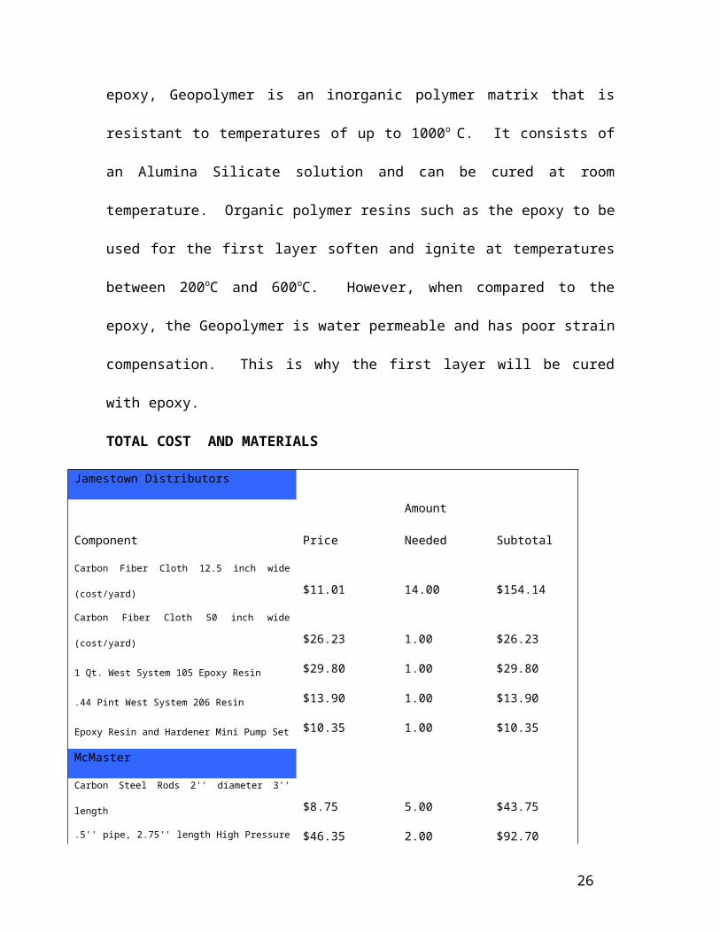
Figure 9
Figure 10
The pressure vessel was examined for leaking at 20 psi. Minor leaking did occur but it
did not effect the performance at the pressures tested. The pressure was then increased to
26

70 psi, followed by 100 psi. The pressure was held and no failures occurred aside from
the slight leak somewhere on the cylindrical body. These results show that it is very
difficult to hand construct a cylindrical pressure vessel with spherical end caps using
carbon fiber cloth. Although all layers overlapped there was still a leak possibly due to
misalignment of strips or not enough epoxy. The geo-polymer did not stick well to the
Original Design Goal
Our original design goal was to create a pressure vessel comprised of carbon fiber/ epoxy
matrix material. We were to use the fibers oriented at 0 and 90 degrees for a total of six
layers. Our end result was constructed completely of carbon fiber epoxy. Our design was
the first design to include carbon fiber epoxy end caps. Previous groups used PVC piping
end caps, attaching them with epoxy. These groups found that failure always occurred
where the caps were attached, forcing us to find a better and stronger design. The design
we used was to have spherical end caps made from carbon fiber strips oriented offset
from each other. This after testing was found to be very strong, causing no failure at the
ends, solving the design failures of the other groups. However with this problem solved,
another one arose in our testing. While testing a leak occurred somewhere along the
cylindrical body, showing that our design may have been good, however our construction
may have had a flaw. Since this vessel was built by hand, there is going to be some sort
of human error associated, especially this being our first manufacturing process.
However, with this mind we still completed our original design goal and improved on last
years.
27

Future Plans
The most important thing that would be solved in future work would be the
manufacturing process. Other procedures instead of manual construction could be used,
like filament finding, to create a more precise and overall better final product. Also for
future reference, it would be beneficial to create more than one vessel so the
manufacturing process would be smoother and each successive vessel will be an
improvement on the previous one. If more precise manufacturing processes couldn’t be
employed, some improvements to the current manufacturing process could be
incorporated into the design to enhance the overall quality of the final product. For
Example, during the process, we learned that using different techniques for the carbon
fiber lay-up would have been more efficient. The resin used had a relatively fast drying
time so the team had a very short amount of time to lay up a layer of carbon fiber. With
practice, we learned that it was better to work with small batches of Epoxy at a time and
consecutively make more as the lay-up process goes along. Also, all of the layers should
be laid up consecutively right after the other one, this ensures that any irregularity on the
surface could be covered up by the next layer and thus resulting in a much smoother and
uniform pressure vessel. Another thing that could have been employed was the use of a
Vacuum bag. This would have ensured that the space between layers would have been
drawn out, greatly enhancing the strength, uniformity and quality of the pressure vessel.
The last important point that the team learned in the manufacturing process was that of
Geopolymer resin is not suitable for use in a pressure vessel. Since the resin does not
have any strain capacity, it cracks easily. Some component would have to be added to the
28

Geopolymer resin to increase its strain capacity in order to be considered suitable in
pressure vessels.
29