Embed Size (px)
DESCRIPTION
Â
Citation preview

MAXIMILIAN MURRAYSTUDIO 5 VICTOR+FINN
s t u d i oAIR

2

3


My name is Maximilian Andrew Murray.
2014 is the 3rd year of my undergraduate degree at the Uni-versity of Melbourne, a Bachelor of Environments (Majoring in Architecture). I have some minor work experience in the ‘real world’ of archi-tecture. I spent a 2 month internship at DP_Toscano Architects in Collingwood, Melbourne. DP_Toscano is a small to medium sized firm, comprising 7 staff and 2 directors, Joe Toscano and Dino Pezzuti, who both worked for a time under Graeme Gunn, a serious hero on the Australian architectural landscape. Their projects range from small residential extensions to bigger scale office and apartment buildings. During my time there I developed an understanding of AutoCAD, Adobe Photoshop and Trimble Sketch-up. That, however, is where my computer intelligence effectively ends. My grasp of algorithms that design forms and systems is virtually nil. I have a feeling that’s about to change.

CONTENTSPART A
A.1 DESIGN FUTURING
A.2 DESIGN COMPUTATION
A.3 COMPOSITION/GENERATION
A.4 CONCLUSION
A.5 LEARNING OUTCOMES
PART B
B.1 RESEARCH FIELD
B.2 CASE STUDY 1.0
B.3 CASE STUDY 2.0
B.4 TECHNIQUE: DEVELOPMENT
B.5 TECHNIQUE: PROTOTYPES
B.6 TECHNIQUE: PROPOSAL
B.7 LEARNING OBJECTIVES & OUTCOMES
PART C
C.1 DETAILED DESIGN
C.2 TECTONIC ELEMENTS
C.3 FINAL MODEL
C.4 ADDITIONAL LAGI BRIEF REQUIREMENTS
C.5 LEARNING OBJECTIVES & OUTCOMES
APPENDIX -
ALGORITHMIC SKETCHES
5
12
14
18
18
25
30
38
44
50
52
54
57
68
76
86
87
88

5

PART A

7
A.1 DESIGN FUTURING
In searching for precedents to analyze, I have been drawn to 2 wildly opposing, but in their own times, wildly modern pieces of architecture that shape and have shaped the world around them in profound ways. Both represent steps towards a new age in terms of design as a whole discipline, at similar mo-ments in time to the “critical moment in our existence” that is described by Fry1, a point that we are at NOW.
Gerrit Rietveld’s Schroder House, which is 90 years old this year, is one of those architectural pieces that helped to usher in a new way of thinking about design and is also one of the buildings that make me want to practice architecture as a career. The members of the De Stijl movement produced many groundbreaking 2D artworks, stripping the representation of objects
1 Tony Fry, Desing Futuring: Sustainablilty, Ethics & New Practice, (Oxford: Berg). 1
The Schroder House, designed by Gerrit Rietveld in 1924, is an eternally relevant piece of architecture
back to the barest and purest forms and colours. But the Schroder house allowed those ideas on the 2D plane to be experienced in the tactile physical 3D world, creating a new type of form making in architec-ture.
The building is a museum today, but was designed as a home for the widow Mrs Schroder and her 3 children. This stresses even further the innovation inherent in the project. This is not the design of a workshop or a factory but rather that of a home. This radical re-interpretation of type is exactly

8 what the LAGI competition is all about. We are required to break the mould and think creatively in terms of sustainable energy, exploring the forms of technologies that are crucial to the ongoing survival of all humanity. Similarly, in the Schroder House, the amount of light, colour and space can be seen as a direct reaction to the dark and claustrophic qualities of some more traditional urban dwellings. The Schroder House even in fact shares a parti-wall with a row of such traditional housing1.
It was without a doubt a radical building for its time, and it was extremely influential in the development of modern architec-ture. Le Corbusier’s Villa Savoye, for instance, would be be started 4 years after the completion of the Schroder House. However, it is of more interest in this studio due to the manner of its conception. After all, it was only due to close collabo-ration with the client Mrs Schroder-Schrader that the build-ing was able to be realised. If we are to work with “design intelligence” as described by Fry2, then working closely with those others involved in the building process, quite clearly, is absolutely critical.
More than anything though, Rietveld and the other members of the De Stijl were striving towards a utopian vision of the future in their designs. A future that has not eventuated. But, the people like Rietveld, responsible for these projects, were designing in a climate of turmoil just like we are today. How-ever, it is also a distinctly different time, and as Fry asserts3:
1 Rob Dettingmeijer et al, Rietveld’s Universe, 2022 Fry, Futuring, 103 Fry, Futuring, 15
Interior perspective showcases the light, colour and vibrance of the design. it still looks cutting edge today
Unlike modernist design utopianism
the presented focus of change is
upon the pro-cesses of redirec-
tion rather than of form. What is
put forward offers no vision of ‘a
brave new world’ but rather design as a ‘redirective practice’ able to take the diversity of humanity away from deepening the disaster of unsustainability toward the futur-ing character of sustain-ability.

9From one extreme to the other, and back to the 21st century, Archim Menges is one Architect who seems to be embracing this concept of ‘re-directive practice’. De-signed in collaboration with Oliver David Krieg and Steffen Reichert, the Hygro-Skin - Meteorosensitive Pavilion is expanding future possiblities with its innovative application and combination of materials, computational design and robotic pre-fabrication1. The project represents a step in the right direction in terms of ‘design intelligence’, with the use of cutting edge technologies to create, or even rather to manipulate materials in such a way as to gain maximum efficiency from their fundamental properties. In this case, the pavilion’s digitally engineered plywood walls house apertures of thinner ply that biologically respond to fluctua-tions in in humidity. Why this is so exciting though, is the fact that this might just be the beginning! Particularly in the context of the LAGI competition, where sustainability is one of, if not the main concern, a project such as this one really broadens the scope and encourages you to think outside the square.
This method of architecture has the potential to radi-cally alter the way in which design is thought about in the context of a modern world. I certainly emphasises this idea of ‘design’s continually growing importance as a decisive factor in our future having a future’2.
1 “HygroSkin: Meteorosensitive Pavilion” Archim Menges.net, published 2013, http://www.achimmenges.net/?p=56122 Fry, Futuring, 3
Above right: the meteorosensitive apertures open and close without any mechanical interventionAbove: Interior of the pavilion. Light is able to penetrate the plywood apertures even when they are closed.Overleaf: External view of the pavilion, Schroder House comparison

10

11

12
SUSTAINABLE ENERGY- WAVE POWER
In beginning the design process for the LAGI Competition, it is ideal to narrow our focus to one form of sustainable energy, in order to zero-in with more efficiency on a suc-cessful design solution, and determine relative precedents, from a far more manageable selection.
‘Wave... is a variable, pulsating form of energy’, states the Bombora Wavepower web page1. The fact that the LAGI site in Copenhagen is surrounded on 3 sides by water, makes extracting energy from that water quite a logical step to take. The Bombora system, devised by West Aus-tralian engineers Glen and Shawn Ryan, harnesses the under water power of waves, capturing the force through the use of a giant flexible membrane that acts like a foot pump on on air turbine2.
Using an underwater system creates a new set of possibili-ties and challenges when applied to the LAGI brief, the ac-tual site extending nearly 64m into the water on the west-ern side. Such a practical process could be transformed into an underwater light spectacle for example. such a basic design idea could be further enhanced through some basic parametric modelling.
1 “ Overall Features” Bombora Wave Power, last modified 2013, http://www.bombo-rawavepower.com.au/technical2 “ Overall Features” Bombora, 2013
Another possible source of wave power comes from the Pelamis System. Already implemented in places off the coast of Scotland and Portugal1. The machine itself con-sists of 5 tubes, connected by joints that flex in 2 direc-tions. Floating on the surface semi-submerged, The Pe-lamis therefore captures energy directly from the surface, with 1 machine capable of meeting the annual energy needs of about 500 homes2.
Such a large scale system as the Pelamis would not be practical for the LAGI site, as the machine operates in water depths of 50m and over3. However the same idea, albeit used on a smaller scale, could produce some inter-esting results. Using the concept of the ‘sea-snake’, in a similar way to the Pelamis, as a paramater for an algorith-mic design would no doubt create some unique forms that would also be applicable as wave power devices.
1 “Pelamis Technology”, Pelamis Wave Power, last modified 2013, http://www.pelamiswave.com/pelamis-technology2 “Technology”, Pelamis, 20133 “Technology”, Pelamis, 2013

13
Above: A simple diagram illustrating how the Pelamis system works and a photograph of it in use.
Above: Illustration of the Bombora system of wave energy capture

14
T I E D T O T I D E TURPIN + CRAWFORD STUDIO
“Tied To Tide is a kinetic artwork activated by the natural
forces of tide, wave and wind. Hinged to the boardwalk,
floating planks and airborne ladders combine with the
ever-changing elements to perform an aquatic dance on
the harbour. Conceptually, the artwork adopts and trans-
forms the maritime language of the site’s timber boardwalk
and access ladders. Free of their prosaic constraints, they
play with rather than stand against nature. The ordinary
becomes the extraordinary as timber boards hover over
the water balancing tilting ladders like unwieldy acrobats in
a harbourside circus.”1
1 http://turpincrawford.com/project/tied-tide
While this exquisite installation by the Turpin + Crawford
studio has little to do with parametric design, it is a very
relevant precedent when considering the LAGI brief. It is
an engaging, responsive, interactive artwork that uses the
natural forces inherent in the waves, wind and tide to drive
a dynamic yet simple deisgn system. It feels as if all that
would be needed to do to make this design applicable for
the LAGI competition is add a pump, or turbine generating
electricity somehow to its moving parts!

15

16
A.2 DESIGN COMPUTATION
design would have been painstakingly difficult and proba-bly impractical without the aid of computation to keep track of all those minute changes in depth. As Kalay argues, it’s all about communication, being able to successfully create a “symbiotic design system”1 between the designer and the computer, an idea that was completely foreign to the Architects of less than 50 years ago.
That is part of the reason why these new methods are so appealing, because for all the generations up until these last few, they have not been possible.
1 Yehuda Kalay, Architecture’s New Media: Principles, Theories, and Methods of Computer-Aided Design (Cambridge, MA: MIT Press 2004), 3
ANEMONEOYLER WU COLLABORATIVE
“Parametricism has been heralded as the new avant-garde in the fields of architecture and design—the next “grand style” in the history of architectural movements”1. The world of design is shifting towards computation and parametricism in the search for solutions and forms that were not possible before. This shift is not solely related to the design of forms, however. Parametric design is also capable for the digital modelling of construction systems that allows these often incredibly complex systems to be realised as installations and pieces of architecture.
In ‘Anemone” an installation designed by the Oyler Wu Collaborative (Dwayne Oyler and Jenny Wu), the benefits of using computational design are clear. Its thousands of flexible, transparent rods are inserted into holes of chang-ing depth, giving the surface is undulating quality. Such a
1 “Politics of Parametricism”, RedCat, last modified 2013, http://www.redcat.org/event/politics-parametricism

17
myTHREAD PAVILIONJENNY SABIN STUDIO
Similar in a way to the development of other architectural phenomena, such as the evolution of the skyscraper, new technologies create new ways of designing.
Geometric complexity is certainly a trait of parametric design, something evidenced in Jenny Sabin’s Pavilion, designed for Nike in 2012. In this installation also, the ma-teriality with which this geometry is achieved makes it all the more interesting, that material being wool. Such “mate-rial experimentation and innovation”1 is very much a part of what Oxman & Oxman describe as “digital architecture”2, that has evolved, particularly in the past decade, to the point, argues Oxman, that “a second nature” can be devel-oped, design that is informed by processes and responses
1 Oxman, Rivka and Robert Oxman, Theories of the Digital in Architecture (London; New York: Routledge 2014), 72 Oxman & Oxman, Theories, 7
in the natural world. Indeed, the Meteorosensitive Pavilion discussed in A.1, is a great example of this, based on the natural charecteristics of the spruce cone1.
Computation has allowed architecture, and design as a whole, to evolve very rapidly in a relatively short space of time. In this intense, digital media driven age that we live in, technology and software is being updated, it seems, almost continuously. It appears inevitable that more and more architects and designers will take up and embrace this new era where computation, parametrics and algo-rithms are used to enhance our ability to respond success-fully to design problems.
1 HygroSkin, Menges.net, 2013

A.3 COMPOSITION/GENERATION
“Computation... allows designers to extend their abilities to deal with highly complex situations”1. There can be no doubt that new design methods and systems, based on computed algorithms, present designers with whole other ways of problem solving, but particularly “puzzle-making”2. Take Plasma Studio’s interior for the the Hotel Puerta America in Madrid, Spain3. Without a computer generating forms like those virtually instantly, with thousands of pos-sible variations available by making simple changes to the script, such a design would not be practical. However the potential for such generations facilitates the potential for these new, often bizarre environments. The design is an-other that strives to break from type (similarly to previous examples i.e. the Schroder House), with Plasma Studios stating that they wanted to move away from the “linear bands of repetitive units with anonymous, undifferentiated corridors”4 that often characterize hotel layouts.
1 Brady Peters (2013) ‘Computation Works: The Building of Algorithmic Thought’, Architectural Design, 83, 2, 102 Kalay, Principles, 93 Hotel Puerta America, Plasma Studio, last modified 2013, http://www.plasmastudio.com/work/Hotel_Puerta_America.html4 Hotel, Plasma, 2013
18
MULTI-FUNCTIONAL BENCHKNUCA WORKSHOP/KG’MG
Brady Peters argues that for computation to become truly connected to architectural design, it needs to stop be-ing discussed as “something different”1. In order for this to happen, i believe, the current shift that is taking place towards generative systems to create designs will need to be taken further, to a deeper level of architecture. Cur-rently, many of these generative designs exist purely as installations or facades. Michael Hansmeyers columns for example, showcased in week 3’s lecture, while they are astounding example of what parametric design is capable of, they do not serve the practical purpose of a real col-umn, for that, as Hansmeyer stated, they require reinforc-ing steel in order for them to become load-bearing.
1 Peters, ‘Computation’ 15

19
HOTEL PUERTA AMERICA LEVEL 4PLASMA STUDIO

20
Michael Hansmeyers columns on display at the Gwangju design biennale
KG’MG bench in use at KNUCA

21
That said, however, if there is one thing that is apparent about the nature of the digital world, it is that it is constant-ly updating and reinventing itself. So while now, this way of creating ridiculously complex form systems is not entirely practical or pragmatic, who’s to say that within the next decade, this isn’t exactly what they will be? Peters stress-es also that “these concepts must be tested in practice through designing and building”1, which is exactly what has been happening over the last couple of years.
Training in script writting for parametric design has also started to become more widespread, and is hopefully moving away from a few individuals with “lone gun” men-talities2. These positive educational steps are evident is projects such as Ukrainian Architects KG’MG’s “Workshop Parametric Interactions”. Students from the Kiev National University of Construction and Architecture (KNUCA) came together to take part in the collarborative workshop that resulted in the design and construction of a multi-purpose, public bench, which can be seen in use on the opposite page.
The techniques involved in parametric design continue to evolve, and new ways of reacting to the shift away from more traditional ways of design are also emerging, with at least 4 distinct methods for handling computational design-ers within architectural firms3, for example. The internet is a powerful tool, and it allows designers to communi-cate quickly and simply across countries and continents, sharing ideas and methods in cyberspace, such as in the Grasshopper forums. The fact that algorithms have a “finite”4 set of parameters means that parametric design methods will inevitably overlapp to some degree or other across a great variety of projects.
Although most of these projects still exist only in the computers in which they were created, more and more, computer generated geometries are being fabricated and constructed. It appears only a matter of time before “computation can become a true method of design for architecture”5. Hansmeyer also says of his forms, with an air of almost triumphant ineveitability “We will build them”, and I’m inclined to think he’s right.
1 Peters, ‘Computation’, 152 Peters, ‘Computation’, 153 Peters, ‘Computation’, 114 Robert Wilson & Frank Keil, Definition of ‘Algorithm’ The MIT Encyclopedia of the Cognitive Sciences (London: MIT Press 1999), 115 Peters, ‘Computation’, 15

22
A.4 CONCLUSIONIn summary, computational design is taking serious steps towards pervading the design world in a more mainstream sense. It is a fully fledged international design movement that appears to be attempting to break from more tradition-al design methods. It is all about challenging the world of architecture to embrace the new possibilities that paramet-ric design can produce. The most exciting thing perhaps is the fact that now we can create forms and designs that un-til very were simply not possible at all and it is in this spirit that I will continue to design in for the rest of the semester.
I feel like the future of architecture lies in generative, computational designs that, rather than being arbitrary, are based on a set of systems that allows the architecture to achieve a higher purpose. As seen in Archim Menges’ Me-teorosensitive Pavilion, and touched on by Michael Hans-meyer in his TED Talk, generative design can be used as a tool that works innovatively with natural systems, to create designs of optimum fuctionality and beauty. Designing in this way could allow architecture to move away from the often unsustainable practices of the present, to a world in which they are integrated into the very fabric of nature, and ending the built environment’s often adverse affect on the natural environment.
This also ties in with what the LAGI competition is trying to achieve. We are attempting to use sculpture to extract energy from natural systems, it would surely make sense to design in close collabortion with those same systems in order to achieve a successful, innovative, design outcome.
A.5 LEARNING OUTCOMESBasically my knowledge of computational design has increased from virtually nothing a the start of the semester, to now having a fairly sound grasp of computational, gen-erative, algorihtmic designs mean for the future. My under-standing of Grasshopper is still very rudimentary, however, having never even touched Rhino before the start of this semester, I feel like I’ve progressed quite a lot, albeit, with a long way to go before I can really start manipulating the software the way I want to!


PART B

26
B.1 RESEARCH FIELD
We as a team, Min Er Wong, Siu Pui Wong and myself, decided to go with biomimicry as a research field, largely because of the immense and diverse scope that it pres-ents. It seems that for all the problems we face, nature can be looked to for the answer. Whether that be the little beetle in the deserts of Namibia that harvests water from fog using the texture of its skin; or the dimples on the
edges of a humpback whale’s fins that help it reduce drag1; there appears to be a great many inventions that we can learn from in the natural world.
Biomimicry, while it might be a recently coined term, is not necessarily a recent idea. As Janine Beryus, a leading science writer in the field, says, “the last really famous bio-
mimetic invention was the airplane”2, the Wright brothers looked to vultures in order to understand lift and drag. what is recent, is the perceived urgency with which we need to take up nature’s designs and ideas, due to climate change and the adverse affects of intensive pollution of the land, sea and sky, that is changing the fabric of the planet as we know it.
Architecture also has a long history of drawing inspiration from nature’s work (the forest canopy inspired column system of Gaudi’s La Sagrada Familia immediately springs to mind), and the more recently defined field of biomimetic architecture is proving that the built environment can be enhanced in myriad ways by looking to nature.
The Eden Project by Grimshaw, the facade of which can be seen across these two pages, is a great example of this. Inspired by natural systems such as the creation of bubbles, the super strusture is so light that it weighs less
than the air within it3. The geometry used in this project is also of interest to us. The geodesic dome is essentially the most efficient structural, geometric way of replicating a section of a sphere, with the highest ratio between internal
area and external surface area4.
1 Janine Benyus: Biomimicry in action 20092 Janine Beryus, Biomimicry: Innovation Inspired by Nature, (HarperCollins, New York, 1997), 8.3 http://www.ted.com/talks/michael_pawlyn_using_nature_s_genius_in_architecture4 http://www.cjfearnley.com/fuller-faq-4.html#ss4.1
B I O M I M I C R Y

27

28
J Ø R N U T Z O N ADDITIVE ARCHITECTURE: from denmark to australia and back
The Danish Architect Jørn Utzon wrote this in 19481. The concept was to be taken further in his work and in 1965, while working on the Sydney Opera House, he coined the phrase “Additive Architecture” to describe architecture that is based on growth pat-
terns that can be seen in nature2. Such a pattern can be discerned in the exterior tiling of this very same building, which has become, not only Sydney’s, but also Australia’s most iconic structure. It is all pervad-ing throughout Australian culture, right down to the design of the Sydney Football club’s guernseys; it is apart of our collective psyche.
The fact that this icon was produced in Australia by a Danish Architect, makes it all the poignant when considering the context in which this journal is being written, as Australian students attempting to design an innovative, sculptural , iconic piece of architecture in Denmark’s capital, Copenhagen. It is important for us to understand the connection between the two nations, and our task becomes that of giving back to the nation that gave Australia it’s architectural masterpiece.
Just as importantly, Utzon’s Additive Architecture is extremely relevant to our biomimicry approach, not to mention computational design and software such as Grasshopper’s potential for this approach. Palm fronds inspired the ribs which support the sail-like shells of the Opera House and Utzon also looked to the operation of a bird’s wing in flight for the
(proposed) window mullions3. In this age of compu-tational design of course, these systems of variant repetition can be modeled digitally in 3 dimensions, based on the specific mathematics that go into those natural systems. As oppose to being inspired by something, we can now accurately replicate nature via computational design that is “explicit, auditable,
editable and re-executable”4.
1 http://vbn.aau.dk/files/18037260/Kyoto-paper.pdf2 http://issuu.com/editionblondal/docs/jorn_utzon_logbook_additive_architecture/7?e=6121109/20372183 http://vbn.aau.dk/files/18037260/Kyoto-paper.pdf4 Woodbury
“The true innermost being of ar-chitecture can be compared with that of nature’s seed, and some-thing of the inevitability of na-ture’s principle of growth ought to be a fundamental concept in architecture”-
B.1 RESEARCH FIELD

29

30
B.2 CASE STUDY 1A R A N D A L A S C H:T H E M O R N I N G L I N E

31
As prescribed by the course outline, in our team, we chose the Morning Line project by Aranda Lasch as our first case study. It connects with our research field of biomimicry, as well as showing traits cohesive with the concept of Additive Architecture as previously touched on.
The Morning Line takes a set of fractal geometry, applies a pattern to it and extends that, relative to the form of the initial shape. We were particularly interested in the original form of the fractal geometry, how that could be manipulated and changed and also what effects that might have upon the surface pattern. The basis for our different species therefore separated those elements out, Species1 takes the original Grasshopper definition and changes the number of faces within the polygon. These variant pyramids, while they might not look particularly interesting, in fact have potential in the context of generating energy using wave power, potentially acting as a second skin for something like the wave power buoy pictured below.
For our Species2, we took the pattern from the existing algo-rithm, and made that our form, using a pipe component. As the number of sides of the polygon is increased, so to is the complexity of the system, creating something akin to a sym-metrical forest of lines that would be interesting to get inside and explore physically.
For Species3 we tried to grow the geometry to create different setups to the Morning Line approach, however with limited success. It does demonstrate how the geometry could be repeated to create an array within the site but the results from Species2 I think have more far reaching potential applica-tions.

32species 1 species 2 species 3 species 4ITERATIONS
Species1 Species2

33species 1 species 2 species 3 species 4
Species3

34 Species4
In Species4 we changed the nature of the fractal geometry itself, to the maximum extent with the shape before the component broke down. In addition, we extruded the pyramid in the negative direction; a fairly simplistic step, however, literally turning the al-gorthm on its head produced some interesting results and as the number of faces is increased, the more the 3D patterns begin to resemble natural systems. The iteration at the bottom right, for example, immediately struck me as resembling a chopping block that has been continuously pounding with an axe from all different angles. This analogy may seem random, however, the LAGI city, Copenhagen, was initially founded as a Viking fishing village, the axe was the prefered weapon of the Vikings, and they used timber for building their boats and towns. Therefore a pattern such as this one created, I believe does hold some, at least, meta-phoric and esoteric weight and has the potential for further development. Little things like that can give power to forms that would otherwise appear quite arbitrary (e.g. Utzon using the sails of Sydney Harbour as inspiration the Opera House’s concept.)

35Species5
The final species we developed, Species5, involved the same type of approach as with Species4 but using different geometry to achieve an individual result. As our cue we looked to Michael Hansmeyer, who ostensibly always looks to the cube, the purest of geometries, when generating his parametric models1. Again we played with the fractal relationships within the geomtric param-eter, achieveing some unique results that depart totally from the original algorithm of the Morning Line. Here we also explored the possibility of solidifying the pattern on the face beyond a merely decorative element, similarly to our approach in Species2, but on this occasionin conjunction with the overall form of the object.
1 http://www.ted.com/talks/michael_hansmeyer_building_unimaginable_shapes

36
species 1 species 2 species 3 species 4
SELECTION CRITERIA / RESULTSIn the group we decided upon several key criteria points:
— Potential for applicability to the LAGI competition and design brief, how could a simple digital iteration be thought of in the wider context.
— Potential for architectural realisation.
— The iteration should be at least vaguely practical and have the potential to be fabricated
— Some aspect of natural systems should be apparent in the ge-ometry of the iteration
— The form should have a connection to Additive Architecture as described by Utzon, as part of our wider goal for the design.
The 3 chosen iterations reflect some if not all of these con-siderations. It is fairly easy to imagine Iteration 1 as a fully fledged piece of architecture (probably something to do with it’s simple conventional geometry), with the “spaghetti” structures on the facade forming some sort of modern ornament as Moussavi defines it1, making the possibili-ties for its real world definable as either Form, Structure, Screen or Surface2. Iteration 1 appears to have potential in all of these. As for Iteration 2, it clearly resembles some sort of natural branching system, reminiscent of the vein structures within our own bodies. I really don’t know how it would work practically, but I believe it certainly hase the capacity to be built, and is not outlandish, being based on a basic octagonal pyramid. The form has definite scupltural properties, an the natural and yet geometric lines have a certian intrigue about them which would be worth exploring futher, on a more LAGI specific scale.
1 Moussavi, Farshid and Michael Kubo, eds (2006). The Function of Ornament (Barce-lona: Actar), pp. 5-142 Moussavi, Ornament, 9
1 2
Iteration 3 is the most successful of the iterations in my view, due its potential, large-scale architectonic applicability to the site. Specifically the geometry that has formed at the very top of the inverted pyramid structure. I find the struc-tural application of that geometry on the LAGI an intrigu-ing possiblilty, the numerous channels could be utilized to feed water through some sort of turbine system to create energy, with the small platform like sections being used for viewing or as a more continuous park. Whatever the further development, I can see serious potential in the undulating lines on the top of this bizarre geometric waratah.

37
3

38
B.3 CASE STUDY 2B U C K M I N S T E R F U L L E R:M O N T R E A L B I O S P H E R E
For case study 2 we decided to explore the Montreal Biosphere, designed by Buckminster Fuller and Shoji Sadao as the Ameri-can pavilion for the 1967 World Exposition. It is a very well defined geometry with the outer shell consisting of a frequency 16, class 1 icosahedron, and the inner shell a frequency 32, class 2 icosahedron; all of course truncated to form a ¾ dome . To reverse engineer the structure we used the Bullant plugin for Rhino, which allows the construction of these complex icosa-hedrons within a single component. What we failed to realize at the time was that by simplifying the algorithm to such a degree, we decreased the potential for altering the parameters to the required extent for our technique development and proposal, as you will see later.

39

40
We started with 2 geodesic dome components, one inner and one outer shell, with specifications that matched the original biospheres’. Such large numbers proved to be too much for the computer however, and so we reduced both the frequency and radius of the spheres so that Rhino didn’t crash whenever we would change a single parameter. There is certainly some irony in the fact that computerized design is meant to make tasks like this faster, when in fact you waste so much time rebooting when you attempt an algorithm too complicated for your operating system! But that’s beside the point. To create the trusses physically, we ran a pipe component around the curves of the geodesic sphere. To recreate the joint the curve was evaluated and the line intersection points found. Spheres were then inserted on those points. In order to turn the sphere into a ¾ dome we simply trimmed the solid pipes and spheres at the appropriate point. We baked our form and deleted the useless underparts to create the fully double skinned dome.
What we came up with was certainly not a perfect match for the Fuller dome, there are some crucial differences and prob-lems we couldn’t quite resolve. One such was the connec-tion between the inner and outer shells. We had numerous attempts at connecting them in the same way as in the dome, however the lines that we created seemed determined to orientate themselves in as many directions as possible apart from the right one. We experimented with field charges, SDL lines, extruded points and even polygons, but to no avail and eventually we simply ran out of time. The other main depar-ture from the original was in the section below the equator. Here the geometry should be truncated to create a continu-ous ring around the base of the dome, a feat we couldn’t quite manage in Grasshopper. Instead, as shown in our prototype for B.5, the dome is supported on legs.
REVERSE ENGINEERING

41

42
geodesic sphereradius
boolean-•true•false
frequency
evaluate curve
0.000

43
evaluate curve
trimsolid
pipe
sphere brepbox

44
PULLING SKINS FURTHER FROM EACH OTHER
ALTERING FREQUENCY AND BUCKY OF THE ICOSAHEDRONS
MOVING FROM FULL SPHERE TO SHALLOW DOME
B.4 TECHNIQUE DEVELOPMENT

45
PULLING SKINS FURTHER FROM EACH OTHER
ALTERING FREQUENCY AND BUCKY OF THE ICOSAHEDRONS
MOVING FROM FULL SPHERE TO SHALLOW DOME
46
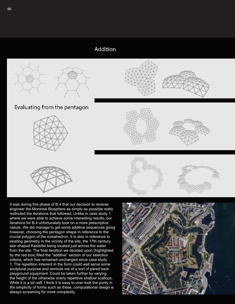
It was during this phase of B.4 that our decision to reverse engineer the Montreal Biosphere as simply as possible really restricted the iterations that followed. Unlike in case study 1 where we were able to achieve some interesting results, our iterations for B.4 unfortunately took on a more prescriptive nature. We did manage to get some additive sequences going however, choosing the pentagon shape in reference to the crucial polygon of the icosahedron. It is also in reference to existing geometry in the vicinity of the site, the 17th century, star-shaped Kastellet being located just across the water from the site. The final iteration we decided upon (highlighted by the red box) filled the “additive” section of our selection criteria, which has remained unchanged since case study 1. The repetition inherent in the form could well serve some sculptural purpose and reminds me of a sort of pared back playground equipment. Could be taken further by varying the height of the otherwise overly repetitive shallow scallops. While it is a bit naff, I think it is easy to over-look the purity in the simplicity of forms such as these, computational design is always screaming for more complexity.
Kastellet LAGI

47
Kastellet LAGI

48
Here we see an extended version of the iteration, demonstrating how additive growth can be applied to the form to achieve a natural repetition of shapes. The three different forms of the pentagon are experiments regarding how these shallow domes would work structurally in the real world. These iterations, with their star-shaped forms, provide an even stronger reference to the Kastellet mentioned before, establishing a link with the past through the comper generating technologies of the future, that could (in theory) strech out and grow our algorithm infinitely.

49

50
B.5 PROTOTYPES
We created two basic prototypes in preparation for our interim presentation. The model seen above was constructed to ex-perience how the geodesic dome is produced in the physical realm, using joint and member. Prototype 2 was constructed to test different magnitudes of height for the shallow dome as part of our final iterations in B.4.

51

52
B.6 PROPOSALOur is basic proposal is to place the geometric form that we have been playing with in our iterations and organise them in some meaningful way on the site. As is made clear by our simple renders, we have not found a particularly effective method for doing this, however, the sculptire does have a stark simplicity that makes its presence intriguing, if nothing else. Also, as part of our overall design intent, we must extract green energy from the water on the site, hence the structural overhangs on the figure bottom right.
As Copenhagen’s waterways are sheltered and not exposed to large wave events, we’ve looked into alternative methods of sea energy extraction, than the more commonly known, deeper sea technologies that have been discussed previ-ously. One such method is capillary action, the movement of liquid without the need for gravity. The structures that make up the sculpture will be hollow in order to facilitate this pro-cess, which would be further enhanced by the use of a capil-lary ratchet to feed water into the pipes. The premise for such a contraption comes from the Red-Neck Phalarope, a small shore bird that rapidly “tweezers” its beak in order to draw water and bits of food up into its mouth1 (see image below). We envisage similar, sythetic versions of this ingenious sys-tem being fitted to the base of these feeding pipes to ensure constant waterflow to drive turbines within the pipes at reqular intervals.
Such movement of water, if the pipes were constructed of a sturdy clear plastic for example, would provide quite a unique spectacle and object, somewhere between power plant and sculpture. We hope to take our ideas to a deeper, more de-tailed level in Part C.
1 http://www.asknature.org/strategy/0c315ac2da0298d1d09ffe17cde027da#.U2TjL1fAGvs

53

54
B.7 LEARNING OBJECTIVES & OUTCOMES
species 1 species 2 species 3 species 4
In terms of learning objectives, I myself have been slow at grasping the concepts presented in the tutorials and have so far been universally falling short of objectives 1 through to 8, particularly in this 2nd part of the semester. Perhaps a change of tact will help engender change in my methods. Clearly, the way I am approaching the course work at the moment is leading me down the wrong paths. Thanks to the feedback received during the interim report, we can now move forward in a more purposeful direction.
After giving a presentation as part of our interim report it has become clear to us as a team that we have not reached the required level of complexity in design or vision with our work so far. Our prototypes were rudimentary and not up to standard and neither were our ideas, particular in relation to the possibilities provided by Grasshopper and Rhino. Our collection of ideas for the proposal was not developed in enough detail and it is clear that we have a lot of catching up to do in the next 3 weeks!
One positive to come out of the presentation however, was the feedback we received regarding our exploration in case study 1 with the Morning Line. Looking back, it seems fairly obvious to us as well that these iterations have far more potential than those that we explored in case study 2. The sculptural potential is clearly far greater and the forms look infintely more interesting. As such we will in fact be abandoning the proposal made in B.6, in order to pur-sue further one of the iterations displayed below, hopefully developing our ideas in more appropriate depth and detail.


56

57
PART C

58
C1. DETAILED DESIGN
Above: Elevation and plan of iterations with increasing fractal divisionsBelow: Isometric view of vector linework with the same algorithm applied.

59
The feedback provided for our interim presentation established basically that a new direction would be required in order to adequately bring out the complex-ity and potential inherent in the assignment. We were also encouraged to explore in greater depth the concept of fractal geometry and its potential to be manipulated through computational design, rather than over simplify-ing in order to make the design appear more feasible.From Part B we carried over an algorithm that extracted curves altered from Aranda Lasch’s fractal geometry for the Morning Line project and turned them into poten-tially feasible 3 dimensional forms. We weighed up the potential of exploring further each of the iterations that were selected at the end of Part B and concluded that we
would continue with the “pipe pyramid” as we called it, a fractal array of winding struts that quite beautifully illus-trates the way in which fractals can be utilized in order to achieve an efficient structural form.
The first problem we had to address of course was how do to generate wave or tidal energy from such a complex and yet simple design. Initially our approach was similar to that of our original proposal. This idea centred on the use of a capillary ratchet system, an idea borrowed from the methods of feeding shorebirds, in which small pincers rapidly open and close, constantly drawing water up into the pipes. This constant inflow of water through the pipes would then drive a turbine (or turbines) which would form the clean energy generator.

60
While this was an attractive and certainly innovative idea for generating electricity, it soon became apparent that fully resolving such a system would become an entire project in and of itself and that we would risk straying too far from the brief in attempting to resolve something that would be better left to a scientific investigation. As such, we decided to move on from the idea of using capillary action to gener-ate electricity and rather explore perhaps more feasible, and yet still innovative methods for harnessing tidal or wave energy.
Further research into wave and tidal energy in Copen-hagen and specifically the LAGI site on Refshaleøen revealed that tidal difference and wave action is relatively miniscule. A minimum of 5 metres tidal differential is usu-ally required to make ventures into tidal energy feasible1, the LAGI site has This led us to look for ways in which to maximize the energy produced through the constant mo-tion of the sea, rather than larger, more standard commer-cial methods. We came up with the concept of attaching a series of these structures to simple piers attached to the sea bed. The actual form we began to create lent itself to the concept of having a strong central element and this also helped solve the energy problem. The structure of the “pipe pyramids” would be constructed of a buoyant mate-rial so that each would float in or on the water like a buoy. As the instability of the ocean surface causes the buoy to bob up and down, the connection back to its central pier would act on a piezoelectric pad generating an electrical current. I feel like this is a far more efficient and innovative use of the technology than something such as a piezoelec-tric floor, where the odd footprint might fall and create a charge. In this case, the “pipe pyramid” buoy is in constant motion, generating a near constant charge and therefore far more electricity…We also looked at potentially adding fairly standard tidal turbines under the water to the piers, in order to generate more electricity, and also so that we could more easily es-timate the amount of energy that the system potential may create, however, feedback from our tutors advised against such an arbitrary solutionAnother potential energy generating solution, and perhaps a more feasible one, is instead of the piezoelectric system, using the same up and down motion to drive a water pump on the inside of the pier, which a small turbine fixed to both the inlet and the outlet
1 http://www.energybc.ca/profiles/tidal.html#treferences
As an installation, the continuous movement of these ad-ditive, fractal structures serve as an almost living, growing metaphor for the creation of electricity within the system. As they are out on the water, viewing platforms will be introduced on or around the structures, allowing users to interact with the design.
Our direction has led us to pay little attention to the land on the site, something undoubtedly driven by the fact that our technology demands the input of water, but also due to the site’s relationship to the opposite bank. The installation will be clearly visible to any of the numerous locals and tourists photographing the iconic Little Mermaid sculpture, which sits directly over the river from the wet area of the stipulat-ed LAGI site, allowing the design to generate interest from afar. The key access point of the water taxi terminal is also nearer to this area of the site.
Potential extra standard tidal turbine to increase energy output of system.
Energy output linked back to central sculpture
Piezo electric pads

61
MATERIALITY
Above: Kastrups Seabath by White arkitekter completed in 2004. The timber pier is in simple, elegant contrast to the curving sea bath enclosure, something that I’d like to see introduced to our design.
Material selection, given the nature of the LAGI brief as well as Copenhagen’s sustainability agenda, has been greatly affected by the need to utilise rercycled or sus-tainable materials. Recycled, reworked PVC pipes are proposed for the construction of the float structure. PVC waste is a world wide, with about one third of Denmark’s PVC waste coming from the construction industry1, and therefore using reycled PVC in construction would be, in a sense, giving something back.The hollow pipes will be made water tight along joints, in order to keep the structure buoyant, failure to do so would undoubtedly lead to the failure of the system.
As for the piers, hot rolled steel hollow columns seem the logical choice, as its structural rigidity will allow for inci-sions to be made to house the connection back to the float.
In a return to simplicity and function that contrasts with the computational form of the floats, the viewing platforms or jetties shall be constructed of recyled timber. Late last year the Danish government passed a bill stating that the timber in all new central government department build-ings must be recycled2, and it would be prudent to follow their example especially in the LAGI context. The Kastrups Seabaths, about a 10 minute drive from the LAGI site on Refshaleoen, is a really useful precedent when consider-ing the use of timber on the water. In this case the west African timber, Azobe was used used, due to its durability in sea water3. Certainly a similar timber will be utilized in our design, albeit the recycled version.
1 http://www.seas.columbia.edu/earth/wtert/sofos/Denmark_Waste.pdf2 Denmark Government required to buy sustainable timber, Daily Timber News,last modified 12 Dec 2013, https://timberbiz.com.au/dtn/details.asp?ID=21523 http://www.archdaily.com/2899/kastrup-sea-bath-white-arkitekter-ab/
PVC piping waste is a worldwide concern.

62
scaled brep
evaluate curve
0.5brep
scaled brep
scaled brep
trimmed brep
trimmed brep
explodebrep
explodebrep
explodebrep
wireframebrep
wireframebrep
wireframebrep
evaluate curve
0.5
evaluate curve
0.5
average
average
average
unsuccessful jitter seed iterations

63
vector 2pt bezier spanaverage
vector 2pt
average
vector 2pt
average
bezier span
bezier span
jitterjitter
jitter
jitter
jitter
jitter
seed#
seed#
seed#
pipe
pipe
pipe
sphere
sphere
sphereradii#
scaled down
scaled down
64
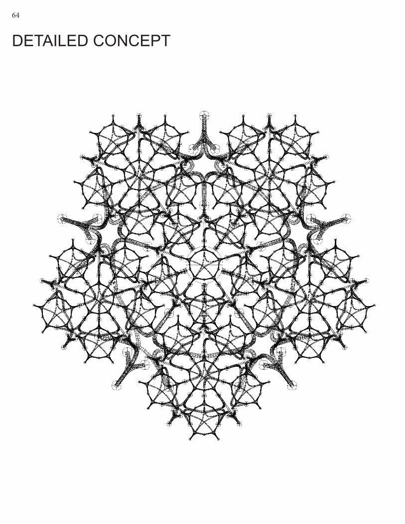
DETAILED CONCEPT

65

66
In terms of the actual fabrication and construction of the proposed system the following steps would be taken:
• Testing of system on small scale• Construction of piers• Prefabrication of sections for pyramids• Assembly on site on temporary pontoon• Connection to on shore generator
undertake surveys of seabed conditions at the site to determine footing system for piers.
fabricate components in factory
rework de-sign with this knowledge
construction of temporary pon-toon for con-struction
CONSTRUCTION DIAGRAM

67
construction of piers, steel & tim-ber
transport components to site floats fixed to piers connection
to on shore generator via under sea cables
68
C2. TECTONIC ELEMENTS
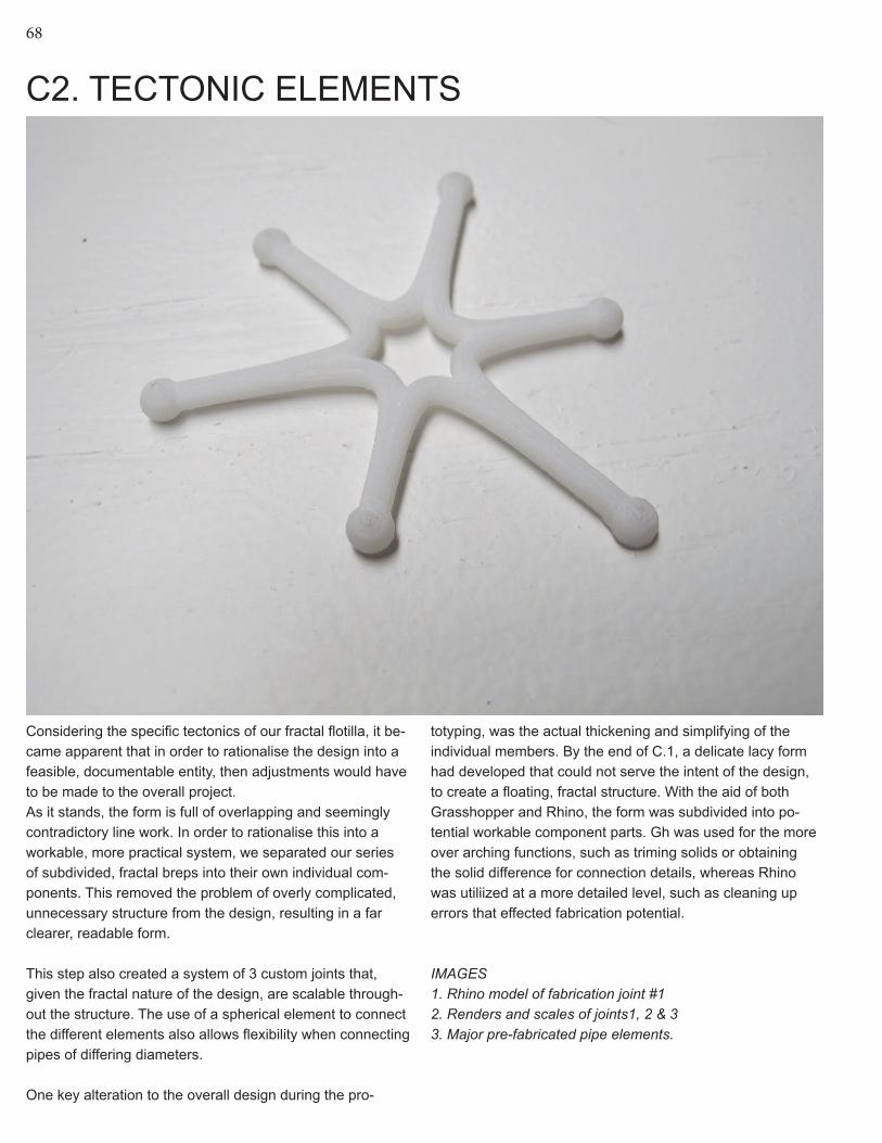
Considering the specific tectonics of our fractal flotilla, it be-came apparent that in order to rationalise the design into a feasible, documentable entity, then adjustments would have to be made to the overall project.As it stands, the form is full of overlapping and seemingly contradictory line work. In order to rationalise this into a workable, more practical system, we separated our series of subdivided, fractal breps into their own individual com-ponents. This removed the problem of overly complicated, unnecessary structure from the design, resulting in a far clearer, readable form.
This step also created a system of 3 custom joints that, given the fractal nature of the design, are scalable through-out the structure. The use of a spherical element to connect the different elements also allows flexibility when connecting pipes of differing diameters.
One key alteration to the overall design during the pro-
totyping, was the actual thickening and simplifying of the individual members. By the end of C.1, a delicate lacy form had developed that could not serve the intent of the design, to create a floating, fractal structure. With the aid of both Grasshopper and Rhino, the form was subdivided into po-tential workable component parts. Gh was used for the more over arching functions, such as triming solids or obtaining the solid difference for connection details, whereas Rhino was utiliized at a more detailed level, such as cleaning up errors that effected fabrication potential.
IMAGES1. Rhino model of fabrication joint #12. Renders and scales of joints1, 2 & 33. Major pre-fabricated pipe elements.

69
1 2
3
JOINT1
JOINT3
JOINT2

70
Material experimentation - using sili-con wrapped around timbers struts to possibly provide an alternative meth-od of obtaining buoyancy

71
3D Printing Prototypeof joint1: scale 1:5

72
JOINT1
JOINT3
JOINT2
3D Printing Prototypewith simplified structure

73

74

75
1:2500 SCALE SITE MODELWith this prototype, the much larger question of tectonics was explored, involving a much wider geographic context. It’s a zoom out, reminding ourselves that we still need to consider the broader problem of the design’s position within Greater Copenhagen.

76
C3. FINAL MODEL

77The final model is on a scale of 1:50 and is composed of 3D printed, laser cut and hand crafted elements. I delib-erately combined these techniques in order to emphasise the contrast inher-ent in the design between, land, water, platform and sculpture and the material tension and complexity therein. Instead of chosing a dense, interior zone, a boundary area is explored, attempting to bring out the connection of the design to the elements particu-larly water, and of course, air.

78

79
LOCATION OF MODEL ON SITE

80

81

82

83

84
F R A C T A L F L O T I L L A The final design is all about the contrast of textures, materi-als and forms. Computational methods allow these buoys to come to life in a way that would not have been possible otherwise, somehow allowing a repeated element to appear different from all angles, just like an object from nature. It is fantastical, an almost ironic interpretation of modern human-kind’s relationship to the world around them.

85
F R A C T A L F L O T I L L A

86
C4. ADDITIONAL LAGI BRIEF REQUIREMENTSThe >>Fractal Flotilla<< brings together the complexity of computational design with rational Danish simplicity. 102 of these fantastical, intriguing float structures are set out on an even grid over the water, within the boundaries of the LAGI site. This contrast between the organic, computational order of the float structures and the simple grid of their arrange-ment is deliberately crafted to reflect the difference between the linear human approach to energy generation, and the infinitely complex way in which nature grows and expands, right down to the atomic level. The individual floats are to capture a sense of this growth by employing a repeating fractal form that could be foreseeably be added to expo-nentially. They are themselves however, trapped within linearly imposed forms in a similar way to that of one of the numerous Nordmann Pine plantations throughout Denmark, a reminder that the purpose of these structures is for the harvesting of a resource, not simply for artistic expression.There is also the role reversal in the tactile, textural experi-ence, with the “natural”, computational form being in fact constructed of a synthetic material (PVC) while the contrived platform that on which you walk among them is natural timber.Each of the identical floats do not have their dimensions arranged randomly either. Their exact size comes from an algorithm identical to the one used to create our >>Fractal Flotilla<< as applied to the scale of the star-shaped Kastellet across the river from the LAGI site. The old fortresses five points were extruded to a single one and then subsequently divided and divided until a workable, practical, but still im-posing scale was established.
DIMENSIONSThe height and diameter of the individual floating buoys are equal and nominally 5555mm each. The pier that the buoy is fitted to comes 3000mm above mean sea level. The jetty that cuts its way through the flotilla is also 3000mm in width. The two levels changes that the jetty undertakes along its north-south axis, take it from 1500 above sea level, to 1000 and finally to 500, allowing the possibility of inundation during high tideand adding to the experience of the overall design. The flotilla covers the large majority of the LAGI site that is over the water, extending over 60 metres out from the waters edge.
THE SYSTEMThe >>Fractal Flotilla<< generates electricity through the continuous movement of the sea surface. Despite the fact that wave heights and tidal differentials are not large in Co-penhagen, by looking to the sea for energy generation, you
introduce yet another dimension into Copenhagen’s “carbon neutral by 2025” agenda, which is currently dominated by solar and wind power. Each separate structure is tied to the sea floor by a single, vertical pier, however the pier and the floatation structure are not actually physically connected. Rather a central, vertically mobile element connects the structure back to itself within the pier, allowing the entire thing to move independently of its anchor. This movable element within the pier is the key to the system’s innovation, as it acts on a piezoelectric ele-ment both above and below via a high tensile spring. This constant movement means that in theory, the piezoelectric electric panel would be giving of a near constant charge. Whether this theoretical system is a feasible one remains to be seen. It would include 204 piezoelectric pads in near constant use, no doubt a system that would require a con-siderable amount of rigour to maintain. The average applica-tion of piezoelectric panels is as a floor tile, where a single footprint can produce around 8 watts of power1. Considering that the buoys in the >>Fractal Flotilla<< would weigh at least 10x that of the average person given there size, each contact with the pad could generate 80 watts. Assuming that every buoy generates at least one charge on a given day, you could therefore potentially generate 7,000kWh of power per annum. this is of course a conservative estimate, as each panel could be charged multiple times during the day, driving the power produced per year up to a far higher amount.
ENVIRONMENTAL IMPACTThe nature of the material selection in the design ensures that negative environmental impacts are minimal. The use of recycled PVC and recycled wharf timbers are steps taken to try and “close-the-loop” on the waste cycle, so that rather than these materials being dumped into landfill, they are reclaimed and used in the ultimate aboutface, to create renewable energy. Obviously the construction process will affect local sealife, however, this problem is not ongoing as no potentially dangerous tidal turbines are being installed in this system.
The >>Fractal Flotilla<< represents an innovative approach to energy generation, previously unexplored, perfect for a city like Copenhagen, sitting as it does, at the vanguard of sustainable practice throughout the world.
1 Doyle, Piezoelectric Energy Harvesting, 2012

87
C5. LEARNING OBJECTIVES AND OUTCOMESIt should be noted at this point that due to continuous com-munication issues and other related problems that impeded our progress throughout the studio, Kaelynn, Vera and I seised working together after the final presentation, going our separate ways to complete the last stage of the journal. This will explain the discrepency between what was shown in the final presentation (an image of which is below) and what is displayed in this journal.
This aside however, I have learnt and developed some valuable skills throughout the semester, which, while they may not have been even nearly perfected, have advanced a great deal for someone with absolutely no knowledge of Rhino or Grasshopper (let alone its millions of plugins) at the start of semester. I think my exploration of python in last couple of weeks is testimont to this. I certainly still have a long way to go when it comes to producing hundreds and hundreds of separate solutions, but I am now able to hop onto grasshopper and start producing things relatively quickly.
It was foreshadowed earlier that this semester would be a steep learning curve for me, and that it has been, and while I may not have fully grasped all the learning objectives for this studio, I’ve definitely had a crack.
*N.B.* Changes to previous sections:P. 14-15, New precedentP. 33, Repeated text removed.

APPENDIX - ALGORITHMIC SKETCHBOOK

89
SCALESSome very quick, rough attempts at con-structing an algorithim that relates to the natural system of scales

90
SHELTER

91
These were the best sketches from a few I did, trying to turn an algorithm we learned in the tute into a more low-lying type of sys-tem. I think I managed to get some groovy intersecting shapes and lines going on here. Surprisingly it is reminescent of the structures built by Bowerbirds in PNG.

92
RADIUSThese were the forms that resulted from the tutorial task of trying to place spheres of decreasing radius on curves, with a correspondingly smaller distance between each sphere. I couldn’t actually figure out how to do that, but I did come up with this weird, pre-historic life form-style pattern.

93

94
CACTUS
This weeks algorithmic task was to create a “cactus” like model. Ended up creating the pretty scary looking thing on the opposite page. The form below was an attempt at the reverse of the cactus, subtracting instead of adding to the loft using a surface difference component. However, for some reason it only decided to work along one horizontal plane. It’s still an interesting af-fect.

95

96
UNDER THE SEAThese tests are designed to create volu-metric spaces through the use of interpolat-ed lines through point charges. The result, especially in the more developed sketch at the base of the spread, was something that resembles seaweed as it convulses beneath the action of the swell. The charges represent a pretty powerful tool on grasshopper, the shapes the create putting control to some otherwise pretty wild lines.

97
98
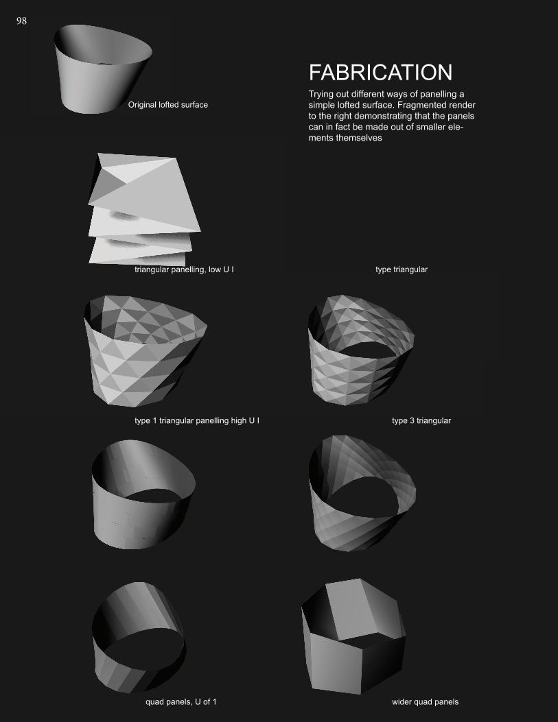
FABRICATIONTrying out different ways of panelling a simple lofted surface. Fragmented render to the right demonstrating that the panels can in fact be made out of smaller ele-ments themselves
Original lofted surface
triangular panelling, low U I
type 1 triangular panelling high U I
quad panels, U of 1
type triangular
type 3 triangular
wider quad panels

99
fragmentation

100
FRACTAL KOCH CURVESAfter being encouraged to explore more deeply the nature of fractal geometries computational design, I had a go at doing a python script that produced a recursive fractal curve after watching a couple of online tutorials.

101

BIBLIOGRAPHY
Part ADettingmeijer, R., Marie-Therese van Thoor, Ida van Zijl (2010) Rietveld’s Universe, (Nai Publishers, Amsterdam)
Fry, Tony (2008). Design Futuring: Sustainability, Ethics and New Practice (Oxford: Berg), pp. 1–16
Kalay, Yehuda E. (2004). Architecture’s New Media: Principles, Theories, and Methods of Computer-Aided Design (Cambridge, MA: MIT Press), pp. 5-25
Oxman, Rivka and Robert Oxman, eds (2014). Theories of the Digital in Architecture (London; New York: Routledge), pp. 1–10
Peters, Brady. (2013) ‘Computation Works: The Building of Algorithmic Thought’, Archi-tectural Design, 83, 2, pp. 08-15
Definition of ‘Algorithm’ in Wilson, Robert A. and Frank C. Keil, eds (1999). The MIT Encyclopedia of the Cognitive Sciences (London: MIT Press), pp. 11, 12
http://turpincrawford.com/project/tied-tide
http://www.plasmastudio.com/work/Hotel_Puerta_America.html
http://www.achimmenges.net/?p=5612
http://www.bomborawavepower.com.au/technical
http://www.pelamiswave.com/pelamis-technology
http://www.redcat.org/event/politics-parametricism
PHOTOGRAPHIC CREDITS
Pg. 7, Ernst Moritz, http://centraalmuseum.nl/en/visit/locations/rietveld-schroder-house/
Pg 8, http://www.archdaily.com/99698/ad-classics-rietveld-schroder-house-gerrit-riet-veld/
Pg 11, http://www.tinadhillon.com/the-schroder-house-utrecht-the-netherlands/
Pgs 9-11 http://www.achimmenges.net/?p=5612
Pg 12, http://www.globalcarbonproject.org/products/SO_ScienceMay07.htm
Pg 13, http://www.bomborawavepower.com.au/technical
Pg 13, http://www.pelamiswave.com/pelamis-technology
Pg 15, http://turpincrawford.com/project/tied-tide
Pg 16, http://oylerwu.com/Anemone.htm
Pg 17, http://jennysabin.com/?p=684
Pgs 18, 20, http://kgmg.org/main.php?l=ru&p=projects&n=39
Pg 19, http://www.plasmastudio.com/work/Hotel_Puerta_America.html
Pg 20, http://www.michael-hansmeyer.com/projects/columns.

103
Part BJanine Benyus: Biomimicry in action | Talk Video | TED.com, 2009http://www.ted.com/talks/janine_benyus_biomimicry_in_action
Moussavi, Farshid and Michael Kubo, eds (2006). The Function of Ornament (Barce-lona: Actar), pp. 5-14
PHOTOGRAPHIC CREDITSPg. 23 http://wall.alphacoders.com/by_sub_category.php?id=177407Pg. 25 http://media.treehugger.com/assets/images/2012/08/wave-power-buoy-27364234.png.492x0_q85_crop-smart.jpgPg. 30 http://c1038.r38.cf3.rackcdn.com/group4/building39427/media/mauc_93700050073c2a19.jpg
Part C
Brian Doyle, Piezoelectric Harvesting, Rutgers University, 2012
Denmark Government required to buy sustainable timber, Daily Timber News,last modi-fied 12 Dec 2013, https://timberbiz.com.au/dtn/details.asp?ID=2152
PHOTOGRAPHIC CREDITShttp://www.archdaily.com/2899/kastrup-sea-bath-white-arkitekter-ab/