Embed Size (px)
Citation preview
Studies on Data Hiding in Digital
Media for Secured Communication,
Authentication and Content Integrity
A report in partial fulfillment for the Degree of
Doctor of Philosophy
in
Computer Science and Technology
Santi P. Maity

Studies on Data Hiding in Digital
Media for Secured Communication,
Authentication and Content Integrity
Santi P. Maity
A report in partial fulfillment for the Degree of
Doctor of Philosophy
in
Computer Science and Technology
Under the supervision of
Dr. Malay K. KunduProfessor, Machine Intelligence Unit
Indian Statistical Institute, Kolkata
&
Dr. Uma Bhattacharya
Professor & Head, Department of Computer Science & TechnologyBengal Engineering And Science University,Shibpur
Department of Computer Science and Technology
Bengal Engineering And Science University, Shibpur
West Bengal, India – 711103
June, 2007

Born-15.02. 1945; Died-10.03. 2007
Dedicated to my revered teacher Late Dr. Prasanta K. Nandi,
Former-Professor & Head, Department of Computer Science &
Technology
Bengal Engineering And Science University, Shibpur
P.O. Botanic Garden, Howrah–711 103
Acknowledgment
Appearance of a thesis in the form of a book like structure takes couple of years to be completed.
During the period I have been enriched in numerous ways by interaction with many people. At
this point, I like to thank those people although I cannot exactly name all of them in this one
or two pages acknowledgment.
At the very outset, I express my sincere gratitude to my revered teacher & supervisor of
this thesis Late Prof. Prasanta K. Nandi, former Head, Department of Computer Science &
Technology of this university for his continuous encouragement, valuable advice and suggestions
which enriched me as well as the content of this thesis. I was really fortunate of getting a
chance to work with him who always listened to me with great patience when I came to him
with research or other academic problems. It is unfortunate that I missed him, when on his able
guidance the thesis was all set for submission, due to his untimely demise. I dedicate this thesis
in his memory.
At this point I express my gratitude to Prof. Uma Bhattacharya, Head and convenor of Ph. D
committee, Dept. of Computer Science & Technology who has kindly agreed to endrose/certify
my thesis after sudden demise of Prof. Prasanta K. Nandi. Almost in the same breath, I
would like to extend my deepest gratitude to other supervisor, Dr. Malay K. Kundu, Prof.
of Machine Intelligence Unit, Indian Statistical Institute, Kolkata. He introduced me with the
subject of digital image processing, research problems studied in this thesis, and most of the
tools and techniques used here. Without his help, I could not even start working in this area
of research. He has been with me throughout the period, accompanying me my lows and highs
with his guidance, encouragement and all the things that he had done in helping me develop my
professional and personal skills. His guidance is surely the necessary and sufficient condition for
completion of this thesis. I look forward his similar technical help and guidance for my future
research and other academic works.
My thanks should go to Dr. Debasish Ghosh, Dean FEAT, Bengal Engineering & Science
University, Shibpur who always reminds me to finish the work and also helps me with words of
encouragement and mental support at one critical part of submission of this thesis. I express
my deep gratitude to Dr. Nil Ratan Bandopadhyay, Chairman, Ph. D cell of this university for
his immense help, suggestion and advice towards completion of submission of this thesis.
I am also thankful to Dr. Mrinal K. Mandal, Associate Professor, Dept. of Electrical
and Computer Engineering, University of Alberta, Canada for his many technical helps and
suggestions. I must also acknowledge the helps and guidance of Prof. Bhargab B. Bhattacharya
and Prof. C. A. Murthy of Indian Statistical Institute, Kolkata. I am also thankful to Dr.
Swasta Chakraborty, Professor and Chairman of G. S Sanyal School of Telecommunication of
Indian Institute of Technology, Kharagpur who helped me with the concept of spatial spread

spectrum image watermarking at the very early part of this research work.
I would like to thank many of my senior colleagues, Dr. Hafizur Rahaman, Dr. Jaya Sil,
Dr. Sipra DasBit, Dr. Abhijit Chakraborty, Dr. Chandan K. Chanda and Dr. N. C. Maity
who always inspired me to finish this work as early as possible. Thank should also be given to
Prof. Partha Bhowmik of CST Dept. of Bengal Engg. and Sc. University, Shibpur and Mrs.
Minakshi Banerjee of Indian Statistical Institute, Kolkata for their help with various sample
tex files while preparing this thesis or writing any paper. I would like to specially thank my
students those who completed their B.E. and M. E. project works under my supervision during
my stay (2000-2006) at Electronics and Telecommunication Dept. of this university. I must also
remember gratefully two of my teachers, Mr. Sakti Prasad Das of my secondary school and Dr.
Ashis Kumar Dey of National Institute of Technology, Durgapur who always ask me about this
work and remind me to be responsible and dutiful for this noble profession.
Lastly my deepest thanks go to my family: my parents, who always show their love, support,
sacrifice and belief in my ability, my elder brother without whose affection, inspiration and
guidance from the very early days of my childhood I could not reach my academic position
where I stay at present. No thank is sufficient to my wife, Seba, who has taken most of the
responsibilities of the family chores; my little son, Subhajyoti, who always eagerly waits for my
return home in the evening and has helped me to recharge my flagging spirit. I express my deep
gratitude to all the relatives who are anxiously awaiting for the thesis to be published. I also
remember all my sisters and sister-in-law (baudi) for their love, affection and inspiration. I also
mention all my nephews and nieces at this point who cheer me up during walk through thorny
journey towards attaining the Doctorate Degree.
At the end, I remember with great sorrow my second elder sister, Mrs. Jharna Jana (Maity)
who died on February 4, 2007 due to sudden electrocution. I believe she would have been also
happy today.
Dated: June, 2007
BESU, Shibpur
. . . . . . . . . . . . . . . . . . . . . . . . . . . . . . . . .
Santi Prasad Maity

Abstract
In this era of digital information revolution, different form of information like numeric &
non-numeric data, image, video, sound etc. are represented in the digital form in order to
avail the cutting edge advantages of digital electronics and computing technologies. The basic
advantages of digital representation are easy and accurate processing, manipulation, storage and
transmission of information. But ease of manipulation and regeneration of digital data have also
created a new class of burning problems such as protection of digital information from illegal
use, duplication, manipulation, security and identification of rightful ownership.
Digital data hiding/watermarking technique, through embedding of an auxiliary message
within the original data, has proven its credibility as a potential & widely used solution for
the stated problems over the last few years. But any watermarking technique developed so
far, is not competent enough to tackle with equal efficiency, the all kind of problems. An
ideal watermarking technique should be capable of handling efficiently problems arising due to
various kinds of deliberate & non deilberate external attacks and offering enough hiding capacity
& visual imperceptibility at low computational cost.
In the present thesis, the design of some data hiding techniques for digital images for secured
communication, authentication and integrity verification have been described. Spatial domain
methods proposed are based on simple and variable channel coding having low cost of compu-
tation and suitable for hardware implementation. Due to these properties, proposed methods
may be used in real time applications for authentication and integrity verification of digital
data. In order to detect the most suitable regions (blocks) to be used for insertion of hidden
information with least visual distortion and considerable degree of robustness, a modified block
based algorithm using image characteristics is also described in the initial chapters of this thesis.
Better imperceptibility in data hiding can be achieved, if watermark image is modulated to
such an extent, that it fits well within the embedding region of the cover. Based on this fact,
two different techniques have been presented for two different domains of implementations. In
spatial domain watermarking GA is used to find optimal values for controlling parameters of
the particular modulation functions. The algorithm is designed for secured communication of
data through innocuous looking image. It is also shown that the imperceptibility in transform
domain watermarking is better achieved by incorporating the properties of human visual system
like frequency sensitivity, luminance masking and contrast masking. These are used to calculate
the embedding strength while designing watermark embedding rule. It has also been shown
that spread transform method can provide better robustness and the use of discrete Hadamard
transform for watermark casting provides robustness against low quality JPEG and JPEG 2000.

Non-conventional use of digital watermarking becomes a popular research focus in recent
times. This is being used in application like the blind assessment of quality of services (QoS)
for multimedia signal in mobile radio environment. In this regard, discrete Hadamard transform
based fragile spread spectrum (SS) watermarking scheme suitable for hardware implementation
has been proposed in this thesis. A novel technique based on channel coding and spatial biphase
modulation for embedding a grayscale watermark in a grayscale cover is also discussed. Ease of
hardware implementation makes this algorithm suitable for authenticating the sender as well as
secured communication of message in real time environment.
Lastly four different robust SS watermarking algorithms using different variants of wavelet
transforms with different distinct advantages have been described. All of these are designed to
achieve higher payload capacity besides other desirable properties as mentioned above. Role of
various factors like properties of the code patterns, signaling scheme, determination of embed-
ding strength, and choice of modulation functions etc have also been studied analytically for
a robust watermark design. Studies have also been done for improvement in payload capacity,
using techniques like code division multiplexing scheme, quadrature carrier multiplexing (QCM)
schemes and interference cancelation methods. A novel biorthogonal wavelet based on Hilbert
transform pairs of symmetric filter coefficients for designing QCM-SS watermarking has been
proposed. For the improvement in robustness further, M-band wavelets and N-ary modula-
tion principle are applied concurrently. The experimental results show how higher computation
cost of decoding for large N-value may be reduced using moderate M-values while robustness
performance remains unchanged.
Usefulness and validity of the proposed techniques have been verified experimentally using
benchmark data. Experimental results amply support the theoretical observations.

Department of Computer Science & Technology
Bengal Engineering And Science University, Shibpur
P.O. Botanic Garden, Howrah–711 103
CERTIFICATE OF APPROVAL
Certified that the thesis entitled Studies on Data Hiding in Digital Media for Secured
Communication, Authentication and Content Integrity, is a record of bonafide work
carried out by Santi P. Maity under our supervision and guidance.
In our opinion, the thesis has fulfilled the requirements of the degree of Doctor of Philosophy
in Computer Science and Technology of the Bengal Engineering And Science University,
Shibpur. The work has reached the standard necessary for submission and to the best of our
knowledge the results embodied in this thesis have not been submitted for the award of any
other degree or diploma.
Dr. Uma Bhattacharya Dr. Malay K. Kundu
Professor & Head, Dept. of Computer Science & Technology Professor, Machine Intelligence Unit
Bengal Engineering And Sience University, Shibpur Indian Statistical Institute, Kolkata
West Bengal, India, 711 103 West Bengal, India, 700 108
Contents
1 Introduction and Scope of the Thesis 1
1.1 Introduction . . . . . . . . . . . . . . . . . . . . . . . . . . . . . . . . . . . . . . . 1
1.1.1 Overview of data hiding in digital media . . . . . . . . . . . . . . . . . . . 2
1.2 Watermarking Principles . . . . . . . . . . . . . . . . . . . . . . . . . . . . . . . 5
1.3 Domain of Implementation . . . . . . . . . . . . . . . . . . . . . . . . . . . . . . 7
1.4 Method of Watermark Casting . . . . . . . . . . . . . . . . . . . . . . . . . . . . 8
1.5 Different Approaches in Digital Watermarking . . . . . . . . . . . . . . . . . . . . 9
1.6 Review of Prior Art . . . . . . . . . . . . . . . . . . . . . . . . . . . . . . . . . . 11
1.6.1 Spatial Domain Techniques . . . . . . . . . . . . . . . . . . . . . . . . . . 12
1.6.2 Transform Domain Techniques . . . . . . . . . . . . . . . . . . . . . . . . 15
1.7 Scope of the Thesis . . . . . . . . . . . . . . . . . . . . . . . . . . . . . . . . . . . 20
1.7.1 Digital Watermarking Preliminaries . . . . . . . . . . . . . . . . . . . . . 21
1.7.2 Spatial Domain Watermarking Techniques [152, 154, 153, 166, 165, 170,
171, 172] . . . . . . . . . . . . . . . . . . . . . . . . . . . . . . . . . . . . 21
1.7.3 Transform Domain Watermarking Techniques [164, 153, 156, 49, 149] . . 21
1.7.4 Spread Spectrum Technique for Fragile Watermarking Design [167, 147,
160, 148, 161] . . . . . . . . . . . . . . . . . . . . . . . . . . . . . . . . . . 23
1.7.5 SS Watermarking for Robustness and Capacity Improvement [157, 158,
173, 155, 162, 163, 159, 168] . . . . . . . . . . . . . . . . . . . . . . . . . . 23
1.7.6 Conclusions and Scope of Further Work . . . . . . . . . . . . . . . . . . . 24
ii

2 Digital Watermarking Preliminaries 25
2.1 Introduction . . . . . . . . . . . . . . . . . . . . . . . . . . . . . . . . . . . . . . . 25
2.2 Properties of digital watermarking . . . . . . . . . . . . . . . . . . . . . . . . . . 25
2.2.1 Imperceptibility or fidelity . . . . . . . . . . . . . . . . . . . . . . . . . . 26
2.2.2 Payload or capacity . . . . . . . . . . . . . . . . . . . . . . . . . . . . . . 26
2.2.3 Robustness . . . . . . . . . . . . . . . . . . . . . . . . . . . . . . . . . . . 26
2.2.4 Security . . . . . . . . . . . . . . . . . . . . . . . . . . . . . . . . . . . . . 28
2.2.5 Computation Cost and Complexity . . . . . . . . . . . . . . . . . . . . . . 28
2.3 Measures of different properties of watermarking . . . . . . . . . . . . . . . . . . 29
2.3.1 Image visual quality . . . . . . . . . . . . . . . . . . . . . . . . . . . . . . 29
2.3.2 Security of the hidden data . . . . . . . . . . . . . . . . . . . . . . . . . . 31
2.3.3 Robustness-capacity measure . . . . . . . . . . . . . . . . . . . . . . . . . 32
2.4 Communications-based Models of Watermarking . . . . . . . . . . . . . . . . . . 33
2.4.1 Amplitude Modulo Modulation . . . . . . . . . . . . . . . . . . . . . . . . 34
2.4.2 Orthogonal and Biorthogonal Modulation . . . . . . . . . . . . . . . . . . 34
2.4.3 Time Division Modulation and Multiplexing . . . . . . . . . . . . . . . . . 35
2.4.4 Frequency Division Modulation and Multiplexing . . . . . . . . . . . . . . 35
2.4.5 Quadrature Carrier Multiplexing . . . . . . . . . . . . . . . . . . . . . . . 35
2.4.6 Code division modulation and multiplexing . . . . . . . . . . . . . . . . . 35
2.4.7 Binary and M-ary Signaling Scheme . . . . . . . . . . . . . . . . . . . . . 35
2.4.8 Quantization Index Modulation . . . . . . . . . . . . . . . . . . . . . . . . 36
2.4.9 Spread Spectrum Modulation . . . . . . . . . . . . . . . . . . . . . . . . . 36
2.5 Applications of data hiding . . . . . . . . . . . . . . . . . . . . . . . . . . . . . . 37
2.5.1 Copyright Protection . . . . . . . . . . . . . . . . . . . . . . . . . . . . . . 37
2.5.2 Copy protection . . . . . . . . . . . . . . . . . . . . . . . . . . . . . . . . 37
2.5.3 Authentication . . . . . . . . . . . . . . . . . . . . . . . . . . . . . . . . . 38

2.5.4 Fingerprinting . . . . . . . . . . . . . . . . . . . . . . . . . . . . . . . . . 38
2.5.5 Secured Communication . . . . . . . . . . . . . . . . . . . . . . . . . . . . 39
2.5.6 QoS assessment . . . . . . . . . . . . . . . . . . . . . . . . . . . . . . . . . 39
2.5.7 Broadcast monitoring . . . . . . . . . . . . . . . . . . . . . . . . . . . . . 39
3 Spatial Domain Watermarking Technique 40
3.1 Introduction . . . . . . . . . . . . . . . . . . . . . . . . . . . . . . . . . . . . . . . 40
3.2 Low-bit Modulation based spatial watermarking using channel coding principles . 41
3.2.1 Algorithm 1: Spatial watermarking using simple channel coding [152] . . 42
3.2.2 Algorithm 2: Spatial watermarking using variable channel coding [166] . . 44
3.2.3 Performance evaluation of LBM based spatial watermarking . . . . . . . . 46
3.2.4 Hardware design[172] . . . . . . . . . . . . . . . . . . . . . . . . . . . . . 52
3.3 LBM based watermarking using image characteristics[154, 153, 166] . . . . . . . 57
3.3.1 Method 1: Selection of blocks based on variance values . . . . . . . . . . . 57
3.3.2 Method 2: Selection of blocks based on average image information . . . . 58
3.3.3 Method 3: Selection of blocks based on average image information and
average edge entropy . . . . . . . . . . . . . . . . . . . . . . . . . . . . . . 59
3.3.4 How to embed watermark bit . . . . . . . . . . . . . . . . . . . . . . . . . 59
3.4 Watermark embedding and extraction . . . . . . . . . . . . . . . . . . . . . . . . 60
3.4.1 Watermark embedding . . . . . . . . . . . . . . . . . . . . . . . . . . . . . 60
3.4.2 Watermark Extraction . . . . . . . . . . . . . . . . . . . . . . . . . . . . . 61
3.5 Performance evaluation of block based LBM methods . . . . . . . . . . . . . . . 61
3.6 Additive watermarking for optimal invisibility . . . . . . . . . . . . . . . . . . . . 63
3.6.1 Algorithm1:GA for improvement in detection of hidden data[170] . . . . . 64
3.6.2 Algorithm 2:GA for optimal imperceptibility in data hiding[171] . . . . . 69
3.7 Conclusions . . . . . . . . . . . . . . . . . . . . . . . . . . . . . . . . . . . . . . . 76
4 Transform Domain Watermarking Technique 77

4.1 Introduction . . . . . . . . . . . . . . . . . . . . . . . . . . . . . . . . . . . . . . . 77
4.2 Watermarking using Unitary Transformation . . . . . . . . . . . . . . . . . . . . 78
4.2.1 Discrete Fourier Transform . . . . . . . . . . . . . . . . . . . . . . . . . . 78
4.2.2 Fourier-Mellin Transform . . . . . . . . . . . . . . . . . . . . . . . . . . . 78
4.2.3 Discrete Cosine Transform . . . . . . . . . . . . . . . . . . . . . . . . . . . 79
4.2.4 Discrete Hadamard Transform . . . . . . . . . . . . . . . . . . . . . . . . 80
4.3 Transform selection . . . . . . . . . . . . . . . . . . . . . . . . . . . . . . . . . . . 81
4.4 Bit Manipulation Technique . . . . . . . . . . . . . . . . . . . . . . . . . . . . . . 83
4.4.1 Method 1: Selection of embedding region using image variance [151] . . . 83
4.4.2 Method 2: Selection of embedding regions based on image information[150,
164] . . . . . . . . . . . . . . . . . . . . . . . . . . . . . . . . . . . . . . . 103
4.5 Additive and Multiplicative Watermarking using Spread Transform Technique . . 110
4.5.1 Non-adaptive spread transform watermarking . . . . . . . . . . . . . . . . 111
4.5.2 Adaptive Spread transform techniques using the Characteristics of HVS
[156, 149] . . . . . . . . . . . . . . . . . . . . . . . . . . . . . . . . . . . . 113
4.6 Conclusions . . . . . . . . . . . . . . . . . . . . . . . . . . . . . . . . . . . . . . . 121
5 Spread Spectrum Technique for Fragile Watermarking Design 122
5.1 Introduction . . . . . . . . . . . . . . . . . . . . . . . . . . . . . . . . . . . . . . . 122
5.2 Mathematical Model of SS Watermarking . . . . . . . . . . . . . . . . . . . . . . 124
5.2.1 Spread Spectrum Watermark Embedding . . . . . . . . . . . . . . . . . . 124
5.2.2 Spread Spectrum Watermark Decoding . . . . . . . . . . . . . . . . . . . 125
5.3 Low cost spread spectrum watermarking[167, 160] . . . . . . . . . . . . . . . . . 126
5.3.1 Watermark embedding . . . . . . . . . . . . . . . . . . . . . . . . . . . . . 126
5.3.2 Watermark decoding . . . . . . . . . . . . . . . . . . . . . . . . . . . . . 127
5.4 Circuit design for low-cost SS watermarking[147, 161] . . . . . . . . . . . . . . . 128
5.4.1 Architecture of watermark embedding . . . . . . . . . . . . . . . . . . . . 128

5.4.2 Architecture of watermark decoding . . . . . . . . . . . . . . . . . . . . . 133
5.4.3 Performance evaluation . . . . . . . . . . . . . . . . . . . . . . . . . . . . 135
5.5 Embedding a Gray scale watermark in a gray scale cover . . . . . . . . . . . . . . 140
5.5.1 Conversion from gray scale watermark to binary form . . . . . . . . . . . 140
5.5.2 Conversion from binary watermark to gray scale form . . . . . . . . . . . 141
5.6 Circuit design for gray scale to binary watermark and binary to gray scale water-
mark conversion[148] . . . . . . . . . . . . . . . . . . . . . . . . . . . . . . . . . . 141
5.6.1 Gray scale watermark to binary watermark conversion . . . . . . . . . . 141
5.6.2 Binary watermark to gray scale watermark conversion . . . . . . . . . . . 145
5.7 Conclusions . . . . . . . . . . . . . . . . . . . . . . . . . . . . . . . . . . . . . . . 148
6 Spread Spectrum Watermarking for Robustness and Capacity Improvement149
6.1 Introduction . . . . . . . . . . . . . . . . . . . . . . . . . . . . . . . . . . . . . . . 149
6.2 Design of Robust Spread Spectrum Watermarking[157, 158] . . . . . . . . . . . . 150
6.2.1 Properties of Code Patterns and their design . . . . . . . . . . . . . . . . 151
6.2.2 Determination of Watermark Embedding Strength . . . . . . . . . . . . . 151
6.2.3 Signal Adaptive Spread Spectrum Watermarking . . . . . . . . . . . . . . 152
6.2.4 M-ary Signaling Scheme[173] . . . . . . . . . . . . . . . . . . . . . . . . . 154
6.3 Space-Spatial Frequency Transformation . . . . . . . . . . . . . . . . . . . . . . . 156
6.3.1 Discrete wavelet transform . . . . . . . . . . . . . . . . . . . . . . . . . . 158
6.3.2 Biorthogonal wavelets . . . . . . . . . . . . . . . . . . . . . . . . . . . . . 161
6.3.3 M-band wavelets . . . . . . . . . . . . . . . . . . . . . . . . . . . . . . . . 164
6.4 Robustness improvement using wavelets . . . . . . . . . . . . . . . . . . . . . . . 167
6.4.1 Choice of Signal Decomposition Tool . . . . . . . . . . . . . . . . . . . . . 167
6.4.2 Choice of Subbands . . . . . . . . . . . . . . . . . . . . . . . . . . . . . . 169
6.5 Payload improvement in SS watermarking . . . . . . . . . . . . . . . . . . . . . . 170
6.5.1 Code Division Multiple Access . . . . . . . . . . . . . . . . . . . . . . . . 171

6.5.2 Biorthogonal decomposition . . . . . . . . . . . . . . . . . . . . . . . . . 172
6.5.3 Successive and parallel interference cancelation . . . . . . . . . . . . . . . 172
6.5.4 Quadrature Carrier Multiplexing . . . . . . . . . . . . . . . . . . . . . . . 172
6.6 SS watermarking techniques . . . . . . . . . . . . . . . . . . . . . . . . . . . . . 176
6.6.1 SS watermarking technique using DWT & CDMA[155] . . . . . . . . . . . 176
6.6.2 SS watermarking using BiDWT & interference cancellation[162] . . . . . . 180
6.6.3 QCM-SS watermarking[159] . . . . . . . . . . . . . . . . . . . . . . . . . . 181
6.6.4 SS watermarking using M-band wavelets & N-ary modulation [163] . . . . 181
6.7 Performance evaluation . . . . . . . . . . . . . . . . . . . . . . . . . . . . . . . . 185
6.7.1 Performance evaluation of DWT based SS watermarking . . . . . . . . . . 186
6.7.2 Performance evaluation of BiDWT based SS watermarking . . . . . . . . 199
6.7.3 Performance evaluation of QCM-SS watermarking . . . . . . . . . . . . . 203
6.7.4 Performance evaluation of M-band wavelets and N-ary modulation . . . . 206
6.8 Conclusions . . . . . . . . . . . . . . . . . . . . . . . . . . . . . . . . . . . . . . . 212
7 Conclusions and Scope of Future work 214
7.1 Conclusions and Discussions . . . . . . . . . . . . . . . . . . . . . . . . . . . . . . 214
7.2 Scope of future work . . . . . . . . . . . . . . . . . . . . . . . . . . . . . . . . . . 218

List of Figures
1.1 Generic digital watermarking scheme . . . . . . . . . . . . . . . . . . . . . . . . . 5
1.2 Generic watermark recovery scheme . . . . . . . . . . . . . . . . . . . . . . . . . 6
1.3 Rectangular region represents the various techniques for digital watermarking
used in this thesis . . . . . . . . . . . . . . . . . . . . . . . . . . . . . . . . . . . . 11
1.4 Flowdaigram that depicts in sequence the works discussed in this thesis . . . . . 22
2.1 Watermarking system with blind detector . . . . . . . . . . . . . . . . . . . . . . 34
2.2 Watermarking system with a simple informed detector . . . . . . . . . . . . . . . 34
3.1 Robustness performance of simple channel coding scheme against various signal
processing operation . . . . . . . . . . . . . . . . . . . . . . . . . . . . . . . . . . 47
3.2 Robustness performance of variable channel coding scheme against various signal
processing operations . . . . . . . . . . . . . . . . . . . . . . . . . . . . . . . . . . 51
3.3 VLSI architecture of watermark embedding . . . . . . . . . . . . . . . . . . . . . 52
3.4 Circuit design of bit select unit . . . . . . . . . . . . . . . . . . . . . . . . . . . . 53
3.5 Circuit design of message extension unit . . . . . . . . . . . . . . . . . . . . . . . 54
3.6 Circuit design of control unit at watermark embedding section . . . . . . . . . . 55
3.7 Circuit design of bit insertion unit . . . . . . . . . . . . . . . . . . . . . . . . . . 55
3.8 Circuit design of watermark decoding unit . . . . . . . . . . . . . . . . . . . . . . 56
3.9 Robustness performance of Method 3 against various signal processing operations 63
3.10 Flow chart for generation of set of points using GA . . . . . . . . . . . . . . . . . 66
3.11 Effect of number of generation on watermark decoding . . . . . . . . . . . . . . . 67
viii

3.12 Robustness performance of median filtering; (a),(b) and (c) indicate retrieved
watermark messages after 1000, 2000 and 2500 iterations respectively . . . . . . . 68
3.13 Robustness performance against JPEG compression; (a),(b) and (c) indicate re-
trieved watermark messages after 1000, 1500 and 2000 iterations respectively . . 68
3.14 Imperceptibility & Robustness performance of algorithm 2 for various transfor-
mation functions . . . . . . . . . . . . . . . . . . . . . . . . . . . . . . . . . . . . 74
4.1 Comparison of processing noise for different transforms . . . . . . . . . . . . . . . 83
4.2 Flowchart for watermark embedding . . . . . . . . . . . . . . . . . . . . . . . . . 89
4.3 Flowchart for watermark extraction . . . . . . . . . . . . . . . . . . . . . . . . . . 91
4.4 (a) Cover image F. Boat; (b)Watermark symbol;(c) Watermarked image; (d)Cover
image Bear . . . . . . . . . . . . . . . . . . . . . . . . . . . . . . . . . . . . . . . 92
4.5 Cover images (a) New York; (b)Opera;(c) Lena . . . . . . . . . . . . . . . . . . . 93
4.6 (a) Cover image Pills; (b) Blurred version of watermarked image Fishing Boat
after applying (3 × 3) mask twice ; (c) Extracted watermark from Fig. (b) . . . . 94
4.7 Robustness performance against Gaussian and median filtering . . . . . . . . . . 95
4.8 Robustness performance against image sharpening and cropping operation . . . . 96
4.9 Robustness performance against bit manipulation and JPEG compression . . . . 97
4.10 Robustness performance against noise addition and dynamic range change . . . . 98
4.11 Robustness performance against rescaling and JPEG 2000 operation . . . . . . . 98
4.12 Robustness performance against collusion operation . . . . . . . . . . . . . . . . 99
4.13 Robustness performance against deliberate embedding . . . . . . . . . . . . . . . 100
4.14 Robustness against change in aspect ratio . . . . . . . . . . . . . . . . . . . . . . 101
4.15 Robustness against small image rotation . . . . . . . . . . . . . . . . . . . . . . . 102
4.16 Robustness gainst lossy compression . . . . . . . . . . . . . . . . . . . . . . . . . 103
4.17 Different binary images with same entropy . . . . . . . . . . . . . . . . . . . . . . 104
4.18 Linear chain representation showing different image blocks . . . . . . . . . . . . . 105
4.19 Watermarked images obtained using image information and after DCT & DHT
domain embedding . . . . . . . . . . . . . . . . . . . . . . . . . . . . . . . . . . . 107

4.20 Graphical representation for change in edge entropy after watermarking . . . . . 108
4.21 Robustness performance against lossy compression . . . . . . . . . . . . . . . . . 109
4.22 Spread Transform watermarking using non-adaptive technique . . . . . . . . . . . 111
4.23 Robustness performance of HVS based adaptive watermarking against various
signal processing operations . . . . . . . . . . . . . . . . . . . . . . . . . . . . . . 118
4.24 Robustness performance of HVS based adaptive watermarking against compres-
sion operation . . . . . . . . . . . . . . . . . . . . . . . . . . . . . . . . . . . . . . 119
4.25 Data hiding capacity of HVS based adaptive watermarking against compression
operation . . . . . . . . . . . . . . . . . . . . . . . . . . . . . . . . . . . . . . . . 120
5.1 Block diagram of SS watermark embedding . . . . . . . . . . . . . . . . . . . . . 127
5.2 Block diagram of SS watermark decoding . . . . . . . . . . . . . . . . . . . . . . 127
5.3 VLSI architecture of watermark embedding unit . . . . . . . . . . . . . . . . . . 129
5.4 VLSI architecture of Walsh transformation . . . . . . . . . . . . . . . . . . . . . 130
5.5 VLSI architecture of WT1 . . . . . . . . . . . . . . . . . . . . . . . . . . . . . . . 131
5.6 VLSI architecture of code generation and spread watermark . . . . . . . . . . . 132
5.7 VLSI architecture of watermark decoding . . . . . . . . . . . . . . . . . . . . . . 133
5.8 VLSI architecture of correlation calculation . . . . . . . . . . . . . . . . . . . . . 134
5.9 VLSI architecture of mean correlation and threshold calculation . . . . . . . . . 135
5.10 Watermark MSE (normalized to 1) versus BER for the coded image data for
different SPIHT compression ratio . . . . . . . . . . . . . . . . . . . . . . . . . . 136
5.11 Watermark MSE (normalized to 1) and coded image data MSE versus BER at
100 Kb/s . . . . . . . . . . . . . . . . . . . . . . . . . . . . . . . . . . . . . . . . 137
5.12 Quality of various offered services at MS after fading, (b) Estimation of the quality
of services from the relative quality of the tracing watermark after fading . . . . 138
5.13 Visual quality versus BER for the coded image data at 100 Kb/s . . . . . . . . . 139
5.14 VLSI architecture of gray scale to binary watermark converter . . . . . . . . . . 142
5.15 Circuit of Majority encoder block . . . . . . . . . . . . . . . . . . . . . . . . . . . 143
5.16 Circuit of Control circuit . . . . . . . . . . . . . . . . . . . . . . . . . . . . . . . . 144
5.17 VLSI architecture of binary watermark to gray scale watermark . . . . . . . . . 145
5.18 Circuit of Controlled complementer circuit . . . . . . . . . . . . . . . . . . . . . . 147
6.1 Tiling of the time frequency plane: (a) as obtained by the WFT (b) as obtained
by the wavelet transform . . . . . . . . . . . . . . . . . . . . . . . . . . . . . . . . 157
6.2 Decomposition & reconstruction using wavelet . . . . . . . . . . . . . . . . . . . 160
6.3 Separable filtering for 2D discrete wavelet transform . . . . . . . . . . . . . . . . 160
6.4 (a) Typical organization of the detail images within the wavelet transform (b)
Example of a wavelet transform of the Lena image depth (3) . . . . . . . . . . . 161
6.5 M-band filter bank structure (M = 4) . . . . . . . . . . . . . . . . . . . . . . . . 166
6.6 Basis tiling in (a) M(=2)-band and (b) M(=4)-band wavelet . . . . . . . . . . . 167
6.7 Correlation between code pattern and image decomposition using a few selected
wavelets . . . . . . . . . . . . . . . . . . . . . . . . . . . . . . . . . . . . . . . . . 168
6.8 Block diagram of watermark embedding using DWT . . . . . . . . . . . . . . . . 177
6.9 Block diagram of watermark decoding using DWT . . . . . . . . . . . . . . . . . 179
6.10 Block diagram of watermark embedding using BiDWT . . . . . . . . . . . . . . . 180
6.11 Block diagram of watermark decoding using BiDWT . . . . . . . . . . . . . . . . 181
6.12 Block diagram of watermark embedding using M -wavelets & N -ary modulation . 182
6.13 (a) Variance of different subbands; (b) Frequency bands corresponding to Mb-
DWT (M=4) band decomposition. . . . . . . . . . . . . . . . . . . . . . . . . . . 183
6.14 Block diagram of watermark dehiding using M -band wavelets & N -ary modulation185
6.15 (a) Cover image, (b)Watermark image, (c)Watermarked image . . . . . . . . . . 186
6.16 Robustness against mean & median filtering . . . . . . . . . . . . . . . . . . . . . 187
6.17 Robustness against gaussian filtering & histogram equalization . . . . . . . . . . 188
6.18 Robustness against image sharpening & noise addition . . . . . . . . . . . . . . . 189
6.19 Robustness against AWGN & spakle noise . . . . . . . . . . . . . . . . . . . . . . 189
6.20 Robustness against dynamic range change & image cropping operation . . . . . . 190
6.21 Robustness against bit manipulation & image rescaling . . . . . . . . . . . . . . . 191

6.22 Robustness against JPEG & JPEG 2000 operation . . . . . . . . . . . . . . . . . 193
6.23 Robustness results for collusion attacks . . . . . . . . . . . . . . . . . . . . . . . . 193
6.24 Cover & watermarked images after multiple watermark embedding . . . . . . . . 195
6.25 Robustness against mean & median filtering for multiple watermark embedding . 196
6.26 Robustness against gaussian filtering & histogram equalization operation for mul-
tiple watermark embedding . . . . . . . . . . . . . . . . . . . . . . . . . . . . . . 197
6.27 Robustness against image sharpening & dynamic range change for multiple wa-
termark embedding . . . . . . . . . . . . . . . . . . . . . . . . . . . . . . . . . . . 198
6.28 Robustness against image rescaling & AWGN for multiple watermark embedding 199
6.29 Robustness against JPEG & JPEG 2000 operation for multiple watermark em-
bedding . . . . . . . . . . . . . . . . . . . . . . . . . . . . . . . . . . . . . . . . . 199
6.30 Conditional pdf for binary decision and error regions . . . . . . . . . . . . . . . . 200
6.31 Effect of BiDWT based multiple message embedding on robustness of first em-
bedded watermark after SPIHT compression . . . . . . . . . . . . . . . . . . . . 202
6.32 Robustness performance against JPEG and JPEG 2000 compression operations
for the two watermarks embedded in two quadrature decompositions . . . . . . . 204
6.33 Robustness performance against additive gaussian noise operations for the two
watermarks embedded in two quadrature decompositions . . . . . . . . . . . . . . 205
6.34 Cover, watermark & watermarked images using M -band wavelets & N -ary mod-
ulation . . . . . . . . . . . . . . . . . . . . . . . . . . . . . . . . . . . . . . . . . . 206
6.35 Effect of the usage of Hadamard basis & channel selection . . . . . . . . . . . . . 207
6.36 Effect of the usage of various modulation functions on detection reliability . . . . 208
6.37 Effect of M-ary modulation on detection reliability . . . . . . . . . . . . . . . . . 209
6.38 BER performance of different N-values for (a) M=2; (b) M=3 under JPEG 2000
compression . . . . . . . . . . . . . . . . . . . . . . . . . . . . . . . . . . . . . . . 210
6.39 BER performance of different N-values for (a) M=4; (b) M=5 under JPEG 2000
compression . . . . . . . . . . . . . . . . . . . . . . . . . . . . . . . . . . . . . . . 210

List of Tables
3.1 Imperceptibility & Security for the hidden data using simple and variable channel
coding . . . . . . . . . . . . . . . . . . . . . . . . . . . . . . . . . . . . . . . . . . 48
3.2 Robustness results after mean and median filtering . . . . . . . . . . . . . . . . . 49
3.3 Robustness results against dynamic range change and JPEG compression . . . . 49
3.4 Robustness results against image sharpening operation and noise addition . . . . 50
3.5 Imperceptibility and security value of the hidden data for various methods using
image characteristics . . . . . . . . . . . . . . . . . . . . . . . . . . . . . . . . . . 61
3.6 Robustness performance against various signal processing operations . . . . . . . 62
3.7 Effect of number of generation on imperceptibility and security measure using
power-law function . . . . . . . . . . . . . . . . . . . . . . . . . . . . . . . . . . . 73
3.8 Effect of number of generation on imperceptibility and security measure using
linear function . . . . . . . . . . . . . . . . . . . . . . . . . . . . . . . . . . . . . 73
3.9 Effect of number of generation on imperceptibility and security measure using
parabolic function . . . . . . . . . . . . . . . . . . . . . . . . . . . . . . . . . . . 75
3.10 Robustness performance against JPEG compression at quality factor of 60 . . . . 75
4.1 Imperceptibility and security value of the hidden data for the proposed variance
based method & comparison with Ho & Shan method . . . . . . . . . . . . . . . 93
4.2 Results of mean and gaussian filtering for the proposed variance based method . 94
4.3 Results of median filtering and image sharpening for the proposed variance based
method . . . . . . . . . . . . . . . . . . . . . . . . . . . . . . . . . . . . . . . . . 95
4.4 Results on robustness against deliberate LSB(s) manipulation and additive noise
for the proposed variance based method . . . . . . . . . . . . . . . . . . . . . . . 96
xiii

4.5 Results on robustness against dynamic range change and rescaling operation for
the proposed variance based method . . . . . . . . . . . . . . . . . . . . . . . . . 97
4.6 Test results of checkmark package for the proposed variance based method . . . . 102
4.7 Imperceptibility and security value of the hidden data for the proposed entropy
based method, Ho and Shan method . . . . . . . . . . . . . . . . . . . . . . . . . 107
4.8 Test results of checkmark package for the proposed entropy based method . . . . 109
4.9 Imperceptibility, security and quality of the extracted watermark for different
values of the embedding strength for Non-adaptive ST method . . . . . . . . . . 113
4.10 Robustness performance of HVS based ST method against various signal distor-
tions for watermarked image Fishing Boat . . . . . . . . . . . . . . . . . . . . . . 114
4.11 Imperceptibility and security value of the hidden data for the proposed HVS based
ST method, Cox & Podilchuk methods . . . . . . . . . . . . . . . . . . . . . . . . 117
4.12 Test results of checkmark package for the proposed HVS based ST method . . . 119
5.1 Result of multipath effect with Rayleigh fading . . . . . . . . . . . . . . . . . . . 138
5.2 Specification of Hardware realization for low cost SS watermarking . . . . . . . . 140
5.3 Specification of Hardware realization for gray scale cover & gray scale watermark
image . . . . . . . . . . . . . . . . . . . . . . . . . . . . . . . . . . . . . . . . . . 146
6.1 Covariance values among DWT subbands after first level decomposition . . . . . 170
6.2 Correlation values among DWT subbands after first level decomposition . . . . . 170
6.3 Correlation values(C) of DWT subbands with code pattern of sets (Pi) and (Pi) 171
6.4 Correlation values (C) of DWT subbands with code pattern (Pi) and (Pi) before
and after modulation using Hadamard kernels . . . . . . . . . . . . . . . . . . . . 171
6.5 Filter coefficients of Hilbert transform approximately for N = 10, K = 4, L = 5 . 174
6.6 The scaling filter coefficients of biorthogonal wavelet bases forming a Hilbert
transform approximately . . . . . . . . . . . . . . . . . . . . . . . . . . . . . . . . 175
6.7 Imperceptibility and security of the hidden data for DWT based SS method . . . 186
6.8 Results of mean and median filtering for DWT based SS method . . . . . . . . . 188
6.9 Result of image sharpening and noise addition for five images . . . . . . . . . . . 189

6.10 Results of JPEG compression for Fishing boat images when code patterns are
and are not modulated by Walsh/Hadamard basis . . . . . . . . . . . . . . . . . 192
6.11 Results of JPEG 2000 compression for Fishing boat images when code patterns
are and are not modulated by Walsh/Hadamard basis . . . . . . . . . . . . . . . 194
6.12 Imperceptibility and security of multiple watermark embedding for DWT based
SS method . . . . . . . . . . . . . . . . . . . . . . . . . . . . . . . . . . . . . . . . 195
6.13 Robustness results of mean filtering for multiple watermark embedding . . . . . 196
6.14 Robustness results of median filtering for multiple watermark embedding . . . . 197
6.15 Robustness results of additive white gaussian noise for multiple watermark em-
bedding . . . . . . . . . . . . . . . . . . . . . . . . . . . . . . . . . . . . . . . . . 198
6.16 Robustness results of JPEG compression in F. Boat image for multiple watermark
embedding . . . . . . . . . . . . . . . . . . . . . . . . . . . . . . . . . . . . . . . 200
6.17 Robustness results of JPEG 2000 compression in F. Boat image for multiple
watermark embedding . . . . . . . . . . . . . . . . . . . . . . . . . . . . . . . . . 201
6.18 Imperceptibility after embedding four (16×16) watermarks using (6, 8) and (4, 4)
BiDWT . . . . . . . . . . . . . . . . . . . . . . . . . . . . . . . . . . . . . . . . . 201
6.19 Imperceptibility, capacity and Pe comparison; first three rows for the proposed
algorithm and last three rows for algorithm in [157] . . . . . . . . . . . . . . . . 203
6.20 Data imperceptibility after embedding two different watermarks using QCM-SS
method . . . . . . . . . . . . . . . . . . . . . . . . . . . . . . . . . . . . . . . . . 204
6.21 Probability of error in single bit, 4-th bit and 3-rd bit during message encoding 206
6.22 Imperceptibility and security of the hidden data using M -band wavelets & N -ary
modulation . . . . . . . . . . . . . . . . . . . . . . . . . . . . . . . . . . . . . . . 207
6.23 Effect of modulation index values on structural similarity measure . . . . . . . . 208
6.24 Test results of checkmark package for watermarking using M -band wavelets &
N -ary modulation . . . . . . . . . . . . . . . . . . . . . . . . . . . . . . . . . . . 211

Chapter 1
Introduction and Scope of the Thesis
1.1 Introduction
O what may man within him hide,
Though angel on the outward side !
William Shakespeare
The well-known adage that “seing is believing” or “picture never lies” are seriously challenged
in the digital world of multimedia. The validity of the old sayings are no longer true always in the
age of Internet Technology due to ability of the pervasive and powerful multimedia manipulation
tools. The impact of revolution in digital information system has opened scopes for innovation
and challenges. As a result, new devices such as digital camera and camcoder, high quality
scanners and printers, digital voice recorder, and multimedia personal digital assistant (PDA)
etc. have been developed which allow consumers to create, manipulate, and enjoy multimedia
data. Developments are also seen in the Internet and wireless network that offer ubiquitous
channels to deliver and exchange multimedia information worldwide. Such developments have
eventually decreased the authenticity of multimedia signals, such as photos, video or audio clips,
claimed to command earlier. These developments result in emergence of some type of problems,
such as protection of digital information from illegal duplication and manipulation, identifying
rightful ownership, security and fair use of multimedia data, are burning issues of the day.
Data authentication technique has been proven to be an efficient methodology for maintain-
ing the content integrity and protection of multimedia data [204, 129, 27]. The method is based
on embedding an auxiliary message within the original data satisfying few essential requirements.
The original data may be analog or digital but in the present thesis, we restrict discussion on data
hiding in digital media. Considerable progress on data hiding methodology has been reported
in recent years from both academia and industry [81, 107, 184, 216, 261, 12, 9, 11, 13, 8, 10].
A considerable attention of research [15, 16, 17, 14] has been drawn towards this relatively new
1

field of research due to its wide range of applications such as copyright protection, data authen-
tication, content integrity verification, security in communication and broadcast monitoring etc.
along with the newly emerging applications areas such as medical imaging, fingerprinting & data
indexing and quality assessment in multimedia communication etc [70, 302, 32, 253, 307]. It is
needless to mention that the requirements and the algorithmic design are not same in all these
applications. So there is a need to develop specific data hiding algorithm to suit the particular
application.
The present thesis describes the development of some data hiding methods in digital me-
dia intended for secured (hidden) communication, authentication and integrity verification. We
move gradually from development of simple fragile data hiding to moderately robust technique
and ultimately reach the robust technique with improved payload capacity. While the objective
of the first two types of techniques are to serve the purpose of authentication, copyright protec-
tion against moderate signal processing, the last type of data hiding techniques can be used for
communication of hidden information. In this thesis, the term secured communication mostly
implies reliable decoding of hidden data against various common as well as deliberate signal
manipulation operations (attacks) rather than simply concealing the very presence of auxiliary
message within the cover data.
This chapter is organized as follows. First, we will present a brief overview of data hiding
in digital media followed by few applications of data hiding. Basic watermarking principles are
then discussed along with domains of watermarking implementation. Contributions of different
disciplines to view digital watermarking problems from different angles are briefly highlighted.
After that, we discuss priori works in this field. Finally, we present the scope of this thesis.
1.1.1 Overview of data hiding in digital media
This section introduces the concept of digital data hiding, the driving force that causes its
appearance, various terminologies and types. This discussion is very brief and general at this
point and details can be found in the latter part of this chapter and in chapter 2. At the very
outset, we state that the merits and demerits of digital domain representation are the primary
cause for the emergence and the popularity of data hiding techniques of that media. On one
hand the digital information revolution and the thriving progress in network communications
offer benefits of perfect communication, the ease of editing, and the Internet distribution of
digital multimedia data. On the other hand the users of digital media are under threat due to the
growing concern of copyright infringement, illegal distribution, and unauthorized tampering. At
this critical point the need for a new technique of security is felt. One such popular solution deals
with an imperceptible embedding of an auxiliary data in the multimedia signals [91, 47, 183].
Although the concept of such information hiding has proven to withstand the test of time[111,
197](for more details of history of information hiding, the reader is referred to [127, 130]), the
2

modern digital data hiding has a rather short history since 1993 [265, 264].
With the wider applications of data embedding in digital multimedia sources, associated
activities like steganography, digital watermarking, and data hiding have also come up. While
steganography establishes a covered information channel in point-to-point connection, water-
marking does not necessarily hide the fact of secret transmission to third party [22]. Functional
classification of watermarking and their need for invisibility is discussed in [275]. In Steganogra-
phy, usually the message itself is of value, and must be protected through clever hiding techniques
and the “cover” for hiding the message is not of value [297]. In watermarking, the effective cou-
ple of message to the “cover”, which is the digital content, is of value and the protection of the
content is crucial. Moreover, digital watermarking demands fulfilment of additional requirement
of robustness against manipulations intended to remove the embedded information from the
marked object. Thus watermarking becomes appropriate for applications where the knowledge
of the hidden data leads to potential danger of manipulation [222]. Explanation and comparison
of terminologies related to information hiding were presented in [107, 216]. However, in order
to avoid unnecessary confusions with similar terminologies, this thesis uses the two terms data
hiding and digital watermarking interchangeably, indicating the fact of imperceptible embedding
of a secondary data into the primary multimedia content.
The original multimedia data that needs to be protected or authenticated is called the
host or cover data or simply cover as it covers the metadata. The embedded data, is usually
called as watermark(s), and the cover data after embedding is called as watermarked data. The
watermark can be used for various purposes based on the applications. The basic advantage
of data hiding method over other protection mechanism of digital media lies in its ability to
associate secondary data with the primary media in a seamless way. The embedded watermarks
can travel with the host media and assume their protection functions even after decoding, while
digital copy protection or prevention mechanism using cryptography [138, 145] are only of limited
value because access to cleartext versions of protected data is at least unavoidable at the paying
receiver end.
Imperceptibility or invisibility of the hidden data, robustness against various signal process-
ing operations for the retention of the embedded data and the ability to hide many bits are the
basic but conflicting requirements for many data hiding applications [276]. Most of the pro-
posed techniques easily meet the imperceptibility demand at the cost of lower robustness. Many
researchers have been focusing on robustness [199, 121, 38], but rarely on the number of bits
to be embedded i.e. payload or capacity [36, 191]. Further, most of the works do not consider
simultaneous robustness to several attacks. Thus, it is a very difficult task to design data hiding
algorithms, in which all these requirements can be achieved with greater accuracy. However,
the problem is tackled during design of algorithm as any specific data hiding application, most
often, does not demand simultaneous fulfilment of all these requirements.
3

Design of data hiding techniques are governed by widely diverse factors such as nature of the
cover data, visibility/non-visibilty of metadata, choice of embedding space, degree of resiliency
against unintentional or intentional transforms (attacks) on the data etc. The type of cover
data leads to the different design issues and methods of data hiding algorithms for perceptual
sources like audio [25, 26, 39], images (binary, colour or grayscale), video [140, 128], and 3-D
graphics [45, 201, 306] differ from that of non-perceptual data, such as text data [48, 178] and
executable codes [228, 255]. The major difference between these two classes of data lies in their
ability of distortion tolerance. Non-perceptual data always needs lossless processing, storage
and transmission and flipping in a single bit may lead to altogether different information. On
the other hand, perceptual data can tolerate a reasonable degree of distortion beyond human
noticeability. This property can be exploited during data embedding either imperceptibly or
with a controllable amount of perceptual distortion.
It is desirable to develop general watermarking methods which can be applied for any type of
perceptual data. As particular sense organ is involved for respective data type, unique treatment
becomes essential while handling each of them. Thus complex knowledge of human auditory
system (HAS) [188, 73] and human visual system (HVS) [290, 291] is essential for designing
efficient data hiding algorithm in audio, image, and video data. Moreover, dimensionality and
causality of the data also demand different types of treatment; processing for 1-D data could
be different for 2-D and 3-D data. Similarly, the techniques or methods can also be different
for progressive data (such as audio and video) and for non-progressive data such as image. In
this thesis, we shall only consider image watermarking case, partly because most of the research
developed so far focuses on images, and partly because most of the concepts that will be discussed
here can be easily extended to the watermarking of different media.
In terms of perceptibility, digital watermarking can be classified as imperceptible and percep-
tible. The objective of the many watermarking methods including the methods discussed in this
thesis is to embed watermark imperceptibly inside the cover to retain the perceptual quality and
the value of multimedia content. The perceptible watermarks create noticeable changes in the
cover signal when added, but do not severely impede the host signal from communicating the
original message. For example, paper marking which usually indicates the origin, the ownership,
and/or the integrity of the document printed on the associated pieces of paper, are perceptible
[53, 181]. Such watermarking is not as popular as imperceptible watermarking, even then they
have been successfully implemented for images by embedding a visible ownership logo which
permits viewing all image details through the watermark.
Imperceptible watermarking can be categorized into two types: fragile [98, 135, 305, 282, 235]
and robust watermarking [83, 224, 35, 158, 237]. Fragile watermarks do not survive lossy trans-
formation to the host signal and their purpose is tamper detection of the original signal. Placing
the watermark in perceptually insignificant portions of the data guarantees data imperceptibility
and provides fragile marking capabilities. In contrast, robust watermarks are embedded in the
4

perceptually significant portions of the host signals so that removal are difficult without severely
degrading the watermarked signal [140]. They are designed to be resilient to intentional attacks:
we define attack as any modification to watermarked signal which can affect the reliability of
the extracted watermark.
1.2 Watermarking Principles
All watermarking methods share the same generic building blocks: a watermark embedding
system and a watermark recovery system. For a more detailed discussion of the general water-
marking framework interested reader can consult [277, 279].
Figure 1.1: Generic digital watermarking scheme
Fig. 1.1 shows the generic watermark embedding process. The input to the scheme is the
watermark (W ), the cover data (I)-an image for example and optional key(K)-for instance, a
random number sequence. The output or the result is the watermarked media, for example, a
watermarked image (I′). The key may be used to enforce security, thus prevents the unautho-
rized parties from the recovering and manipulating the watermark. This key may be regarded as
a portion of the encoding process. The dashed line in Fig. 1.1 indicates that it may be needed
for a particular design. The watermark can be of any nature such as a number, text or an image.
Similarly the cover data may be of any digital media such as audio, image, video, text or 3-D
graphics.
The generic recovery process is depicted in Fig. 1.2. Inputs to the schemes are the water-
marked data (I′) or its possibly distorted version (I
′′), key (K), and, depending on the method,
the original data (I)/ or the original watermark (W ) or some side information about the origi-
nal data. The output is either the recovered watermark W or some kind of confidence measure
indicating how likely it is for the given watermark at the input to be present in the data under
5

inspection.
Figure 1.2: Generic watermark recovery scheme
Different terms have been used in literature. It is reported that in a panel session of the
first Information Hiding Workshop [217], the following terms were agreed. The original media
is called cover-media; the watermark is called embedded message and the marked-media is the
stego-media. However, these terms are not yet very popular and thus in most places of this
thesis, we will use the term original or simply cover to represent the media to be protected
or authenticated, watermark to represent the auxiliary message and the watermarked media
obtained after embedding.
Now we express mathematically the aforementioned processes shown in Fig.1.1 and Fig. 1.2.
We can view the encoding or embedding process as a function or mapping that maps the inputs
I, W and/or K to the output I′; that is,
X′= E(I,W, [K]) (1.1)
where E(.) denotes the embedding process, and [K] indicates that K may not be included.
Similarly, the decoding or extraction process, D(.), can be denoted by
W′= D(I
′′, [I], [K]) (1.2)
and the detection process, d(.), is
Y esorNo = d(I′′, [I],W, [K]) (1.3)
Again, [.] means that the element in the bracket may be optional.
The availability/nonavaiblity of the original, non-watermarked data during dection/decoding
becomes an important property of digital watermarking as it not only controls the performance of
watermarking system but also lead to the algorithmic design intended for particular application.
For example, in a transaction-tracking application, owner of the original media runs the detector
and discovers who illegally distributed a given copy. This often substantially improves the
detector performance as the original can be subtracted from the watermarked copy to obtain
6
the watermark pattern alone. The original can be used for registration, to counteract any
temporal or geometric distortions that might have been applied to the watermarked copy.
There are, of course many applications, where detection must be performed without access
to the original work. Some of the applications include copy control, authentication, security in
communication, fingerprinting and broadcast monitoring etc. These applications of watermark-
ing where distribution of unwatermarked content to every detector is impractical. At the same
time, it would also defeat the very purpose of the watermarking system.
In this thesis, the term informed watermarking is used for both the two cases of detection
or decoding processes. These are detection/decoding process which (i) requires the original,
unwatermarked data and (ii) some information derived from the original work, rather than the
entire work. Conversely, detectors that do not require any information related to the original
data are referred to as blind or oblivious detectors. Some people call this detection technique as
non-coherent detection due to its similarity with non-coherent demodulation of communication
system. However, this terminology is less popular than the former two.
1.3 Domain of Implementation
Watermark embedding can be directly applied to the original signal space of the host docu-
ments or in some transform domain in order to exploit perceptual properties and/or robustness
to certain signal processing operations. For example, direct embedding of the watermark signal
can be applied to the pixel values of a digital image and is known as spatial domain embed-
ding [265, 270]. Many times direct embedding in the original signal space is required for low
cost, low complexity, low delay or some other system requirements. However, the spatial do-
main watermarking algorithms are generally not robust to intentional or unintentional attacks
[278, 280, 295]. Transform domain watermarking for digital images includes discrete cosine
transform (DCT)[119], discrete Fourier transform (DFT) [34], the discrete wavelet transform
(DWT) [244] as well as many other space-spatial frequency transforms & unitary transforms.
Block based discrete cosine transform [131] is an appealing choice as it is a basic component
of image and video compression standards such as JPEG and MPEG family of coders. Global
DCT is also used in order to embed watermark information over whole spectrum of the cover
[83, 80]. Similarly, DWT domain embedding techniques become appealing in recent times due
to its various properties such as better space-frequency tiling, multiresolution analysis, superior
HVS modeling and recent trends in JPEG 2000 compression operation [303, 144].
Digital watermarking started from researches in the design of the algorithms and their effec-
tiveness. The watermark embedding and decoding algorithms and their robustness performance
against various possible signal processing operations are tested through implementation by soft-
ware. In a software implementation, the code representing the algorithm runs on a microproces-
7

sor [177]. Conversely, hardware-based implementation is one where the algorithm’s operations
are fully implemented in custom-designed circuitry. The overall advantage is that hardware
consumes less area and less power. Although it might be faster to implement an algorithm
in software, there are a few compelling reasons for a move towards hardware implementation.
In consumer electronics devices, a hardware watermarking solution is often more economical
because adding the watermarking component takes up a small dedicated area of silicon. In
software, implementation requires the addition of a dedicated processor such as DSP core that
occupies considerably more area, consumes significantly more power, and may still not perform
adequately fast. Thus there is a trend found to turn the well-designed algorithms into practical
products.
Strycker et. al in [257] proposed the implementation of a real-time spatial domain watermark
embedder and detector on a Trimedia TM-1000 VLIW processor. The authors in [71] proposed
a watermark-based protocol for the document management in large enterprises. The authors
in [100] described the VLSI implementation for watermarking techniques, which is one of the
pioneering implementations for watermarking applications. The authors in [177] proposed the
video watermarking algorithms through the hardware implementations of a well-known algo-
rithm called Just Another Watermarking Scheme(JAWS) [128]. Mohanty et al. [187] described
a watermarking chip that has spatial domain robust and fragile watermarking functionalities.
1.4 Method of Watermark Casting
Any watermarking algorithm may be regarded as addition of watermark information to the host
data. In this thesis, we will discuss the following widely used insertion methods irrespective of
domain of embedding or modulation techniques considered. These methods are:
(i) LBM /LBS (low bit modulation or substitution) method where watermark information
is inserted by substituting suitable lower bit plane of the pixel values or suitable transform
coefficients of the cover. These methods are well suited for binary watermark pattern or a
gray-scale watermark image when converted to binary equivalent form.
(ii) Additive: The most common approach to blind embedding is the additive one, where a
scaled version of the watermark message is embedded directly or in transformed cover image.
The additive watermarking can be expressed mathematically as follows:
fw,i = fi + γ.wi (1.4)
where fi, wi & fw,i are the i-th component of the host signal, watermark signal and the water-
marked feature vector. The value of γ is a scaling factor which controls the watermark strength.
8

The main reasons for the popularity of additive watermarking is its simplicity and correlation-
based (under certain assumptions) decoding is optimum, in that either the overall error proba-
bility, or the probability of missing the watermark given a false detection rate, is minimized.
A deviation from the blind additive embedding paradigm, is obtained when the watermark
strength γ is allowed to vary with i, that is:
fw,i = fi + γi.wi (1.5)
The main reason for letting γi depend on i, is that in this way the watermark strength can be
adapted to each host feature in f to better match the imperceptibility constraint.
(iii) Multiplicative: Probably the most important point in watermark casting is to match the
characteristics of the watermark to those of the host signal and this can be met if the larger
host features bear a larger watermark. In other words, the energy of watermark samples be
proportional to the corresponding host features samples and be expressed mathematically as
follows:
fw,i = fi + γi.wifi (1.6)
where the symbols have the same meaning as in Equation (1.4).
The main reason for the success of multiplicative embedding coupled with frequency domain
watermarking relies in the masking properties of the HVS and HAS. The advantages offered
by the multiplicative watermarking are as follows. It is possible to achieve better match of
the invisibility constraint by embedding a watermark whose energy at a given frequency is
proportional to the energy of the image at that frequency. We obtain an image-dependent
watermark, thus increasing system security, since in this case it is more difficult to estimate the
watermark by averaging a set of watermarked images.
We differentiate LBM or LBS techniques from that of additive/multiplicative embedding
method although the former can be consider as a special case of the later. The main point of
distinction arises as it is possible to have zero embedding distortion in the former method when
watermark information match with the bit plane of the cover signal. But in the latter case, data
insertion process must cause some signal distortion whatever be small amount it may be. The
other points of their distinction are discussed later.
1.5 Different Approaches in Digital Watermarking
Digital watermarking is a multidisciplinary research area involving theory of communications,
signal processing, multimedia coding, information theory, cryptography, mathematics and com-
puter science etc. Researchers from these different fields view digital watermarking problem
9

from different angles and develop different models in order to fit them for plurality of applica-
tions. Due to the diversity of the approaches involved in digital watermarking, an exhaustive
discussion of the state-of-the art of the entire area of digital watermarking is beyond the scope
of this thesis. The most relevant approaches considered in this thesis are clarified as follows.
The popular and widely used approach is based on theory of communication where the
watermark is considered to be the signal to be transmitted [37, 243, 136]. The cover may be
thought as part of a communication channel. The objective of modulation process in traditional
communication theory is to change the information bearing signal to suit the characteristics of
channel for reliable decoding at the receiver. Similarly, the objective of digital watermarking is
to embed watermark inside the cover so that it fits as maximally as possible. It is also required
that watermark symbol to be detected/decoded from various possible degraded versions of the
watermarked signal. Cox et. al. [83] used spread spectrum (SS) communication theory to
formulate their watermarking method and made a seminal contribution in the watermarking
literature. Reliable retrieval of the watermark message helps researchers to use appropriate
channel coding [110, 211, 42] and the choice of decoding algorithm [41, 34].
Mathematical theory of digital communication in general and the information theory in
particular was used in digital watermarking system design to evaluate the ultimate limits of the
performance achievable by any watermarking scheme subject to very general constraints, such
as maximum allowed embedding and attacking distortions [195, 194, 189]. Some interesting but
surprising results are obtained by looking at digital watermarking from an information theoretic
perspective. One such result is the independence of watermark detection/decoding reliability
with/without the presence of cover during decoding. Another benefit obtained by looking at
digital watermarking from an information theoretic perspective, is that such an analysis provides
a number of hints on optimal attacking and decoding/detection strategies [259].
Many watermarking techniques have shown improved performance by exploiting the knowl-
edge of signal processing. For example, if embedding distortion is kept to a specific level, the
robustness performance for a SS watermarking scheme using biorthogonal wavelets (BiDWT)
found to be better compared to 2-band discrete wavelets (DWT). This improvement is possi-
ble due to better directional decomposition of BiDWT compared to DWT decomposition. To
achieve both imperceptibility and robustness, researchers use many signal processing tools such
as discrete fourier transform (DFT), discrete cosine transform (DCT), Fourier-Mellin transform,
and wavelets etc.
Knowledge of computer science has also been explored in research of digital watermarking.
Soft computing is one sub-bunch of computer science which is being used widely in recent time
in various forms for performance improvement. Genetic Algorithm (GA) is one potential soft
computing tool that is used for optimizing both the fundamentally conflicting requirements of
imperceptibility and robustness. GAs [205, 204] have been used to improve security, robustness
10

and image quality of the watermarked image simultaneously. Neural network [122] is used
to design robust watermarking for images to take advantages of relatively easy algorithmic
specification, pattern mapping and classification. Chan et al. [62] explored the feasibility of
Support Vector Machine (SVM) to determine automatically where the significant blocks are
and to what extent the intensities of the block pixels can be modified.
In this thesis, we have restricted our attention on the development of various watermarking
techniques only using signal processing, digital communication and soft computing tools which
is schematically shown in Fig. 1.3.
Figure 1.3: Rectangular region represents the various techniques for digital watermarking used
in this thesis
1.6 Review of Prior Art
Over the years, lot of research works have been made by research community in the area of
digital watermarking for protection and other related applications of digital content and many
excellent papers have appeared in special issues [13, 8, 10] as well as dedicated conferences and
workshops [2, 3, 5, 4]. Interested readers may go through [190] for recent works. This section
presents several types of digital watermarking techniques found in the academic literature. We
do not give an exhaustive review of the area, but provide an overview of established approaches.
Watermarking algorithms have been proposed for audio, still images, video, graphics, and text,
11

and excellent review of articles on multimedia watermarking can be found in [295, 258, 221].
In this thesis, we limit the scope of our review to digital images. The existing works on digital
image watermarking can be classified into two broad categories: pixel-domain or spatial domain
embedding, and transform-domain embedding.
1.6.1 Spatial Domain Techniques
There are various possible ways to implement spatial domain image watermarking algorithms.
Among them LSB (least significant bit) substitutions, pixel value difference, channel coding,
quantization index modulation (QIM) and spread spectrum (SS) modulation based techniques
are widely used. LSB based techniques are simplest in implementation and appeared in the
early part of the development of watermarking algorithms. We now briefly discuss few works of
each of the different type already found in the literature.
1.6.1.1 LSB substitution
One of the common techniques is based on manipulating the least-significant-bit (LSB) planes by
directly replacing the LSB(s) of the cover-image with the message bits. LSB methods typically
achieve high capacity. Walton [282] proposed to hide key-dependent check-sums of the seven
most significant bits (MSBs) of grayscales along pseudo-random walks in the least significants
bits (LSBs) of pixels forming the walk. Some of the earliest techniques [270, 296, 269] embed
m-sequences into the least significant bit (LSB) of the data to provide an effective transpar-
ent embedding technique. Good correlation properties of m-sequences are used in watermark
detection. Furthermore, these techniques are computationally inexpensive to implement. In
[296], m-sequence is reshaped into two-dimensional watermark blocks, referred to as variable-
w two-dimensional watermark (VW2D), is added and detected on a block-by-block basis. The
technique has been shown to be an effective fragile watermarking scheme which can detect image
alterations on a block basis. Wang et al. [285] proposed to embed secret messages in the mod-
erately significant bit of the cover-image. A genetic algorithm is developed to find an optimal
substitution matrix for the embedding of the secret messages. A local pixel adjustment process
(LPAP) is used to improve the image quality of the stego-image. The weakness of the local
pixel adjustment process is pointed out in [61]. Wang et al. [286] also proposed a data hiding
scheme by optimal LSB substitution and genetic algorithm. Using the proposed algorithm, the
worst mean-square-error (WMSE) between the cover-image and the stego-image is shown to be
1/2 of that obtained by the simple LSB substitution. These LSB based watermarking schemes
mostly satisfy data imperceptibility requirement but their robustness performance are not good.
Moreover, these algorithms fail to identify the regions of the cover which have been changed. To
address these problems, Maity et al. proposed three block based spatial domain image water-
marking schemes [154, 153, 165] where binary watermark is embedded using LSB substitution
12

of the average brightness values of a set of selected blocks. The watermark embedding regions
are selected based on simple image characteristics of the blocks such as variance values, average
image information, and combined usage of average image information and average edge entropy.
In [153], a new form of entropy function proposed by Pal and Pal [202] is used in order to
capture properly the high spatial correlation among the neighboring pixels. The work has been
extended in [165] by the combine usage of exponential form of entropy as well as logarithmic
form of entropy [247] used to measure the average edge information. It is shown through simu-
lation results that the algorithm proposed in [165] offers best robustness performance compared
to [154] and [153].
1.6.1.2 Pixel value difference
Several spatial-domain watermarking techniques for images are proposed by modifying the rela-
tionship of a particular set of pixel values. These types of watermarking techniques are computa-
tionally efficient, suitable for authentication of visual information and robust to small distortions
caused by compression. One such technique described in [44](Patchwork method) divides the
image into two subsets A & B where the brightness of one subset is incremented by a small
amount and the brightness of the other set is decremented by the same amount. If the pixels in
set A are incremented by one and the pixels in set B are decremented by one, with N locations in
the set, the expected value of the sum of differences between the sets is given by 2N. The value
should go to zero for non watermarked data. In [219] the image is split into random subsets
A and B and the intensity of pixels in A is increased by a constant factor k. This method is
capable of hiding more information in the host signal but the algorithm is vulnerable to lowpass
operations. Extension to this work is found in [199]. According to this paper, robustness of
the algorithm can be increased by grouping pixels so as to form blocks of certain dimensions
e.g. (2 × 2), a fact that enhances the lowpass characteristics of the watermark signal. The
similar type of work is proposed by Queluz et al. [230] for image verifications. A content depen-
dent authentication data is embedded into the picture, by modifying the relationship of image
projections throughout the entire images. To obtain a secure data embedding and extraction
procedure, directions onto which image parts are projected depend on a secret key. In order to
guarantee minimum visibility of the embedded data, the insertion process is used in conjunction
with perceptual models, exploiting spatial domain masking effect.
1.6.1.3 Quantization Index Modulation
A class of widely used blind information embedding technique is quantization index modulation
(QIM) algorithms. Watermarking is achieved through the quantization of the host asset, namely
the host feature vector, according to a set of predefined quantizers, where the particular quantizer
used for the case at hand depends on the to-be- hidden message. Chen and Wornell [67, 68]
13

developed QIM which provides good performance for low channel noise but is not robust when
channel noise power is greater than watermark power. They improved the QIM ideas using
Costa’s approach and named the new scheme QIM with distortion compensation (DC-QIM)[69].
Chen and Wornell also discuss a simplification of DC-QIM where the indexed quantizers are
derived via dithered prototype quantizers. This technique is investigated particularly for the
case of uniform scalar prototype quantizers, which is denoted as distortion compensated dither
modulation. Chen and Wornell present a coarse performance analysis of DC-DM that is based
on minimum-distance arguments and the variances of the watermark and the attack noise.
However, the specific shape involved PDFs (probability distribution function) of the transmitted
and received signals are not modeled accurately so that tight performance limits cannot be
computed.
In Yeung et al.’s work [305], a meaningful binary pattern is embedded and allows the tam-
pering that is confined in some local areas to be located. Walton proposed [282] an approach
by embedding data via enforcing relationships between sets of pixels. Wong proposed a scheme
[299] that divides an image into blocks, then copies the cryptographic digital signature of each
block in the least significant bits of the pixels for future verification.
1.6.1.4 Channel coding
Hernandez et al. [110] applied channel coding scheme in spatial domain watermarking and
obtained the detector structure, analytical bounds for the bit error rate (BER) and the receiver
operating characteristic (ROC). They also pointed out that the use of channel coding, such
as BCH block codes, results in an improvement of BER for large watermark capacities, and
a degradation for small watermark capacities. Therefore, the choice of the channel codes is
important due to their minimum distances and redundancies. Maity et al. use simple channel
coding [152](for binary watermark) and variable channel coding [166] principle (for grayscale
watermark) for developing LSB based spatial domain image watermarking schemes. Adaptive
modulation is used to make the schemes resilient against smoothing filtering operations. Both
methods are computationally efficient and simpler to implement. Maity et al. also develop
hardware realization [172] of the later methods to make the schemes suitable for real time
application of image authentication and integrity verification.
1.6.1.5 Spread Spectrum watermarking
Among the many existing watermark insertion approaches, spread spectrum has been shown
to have very desirable properties. One of the most interesting properties is that narrow band
watermarks are spread over many frequency bins so that the energy in any given bins is very
small and could hardly be detected. Although SS method is widely used, most of the works
14

found in literature employ some typical transformations. Some popular spatial domain SS
methods which have taken care for detection improvement are found in [179, 86, 125, 169]. In
[179], the authors pointed out the desirable properties of the code patterns and three choices of
sequence generation are proposed, namely: traditional pseudorandom generation, deterministic
sequences from Walsh and Hadamard basis, and generation by Gram-Schmidt orthogonalization
of pseudorandom sequences. The authors in [86, 125] suggest to realize image prediction or
whitening before evaluating the cross-correlation (between the code patterns and watermarked
signal) in order to improve detection. Malvar et al [175] proposed an improved spread spectrum
(ISS) method that removes the host signal as a source of interference, gaining significantly
robustness of watermark detection. Although it delivers the same average distortion as in SS
method, forced cross-correlation minimization may cause large local distortion of the host signal.
Langelaar et al. [140] treat host content as noise while designing SS watermarking. In [137],
M-ary modulation technique is used to improve robustness performance in SS watermarking
at the cost of large computation cost and large M -values make them sometimes impractical
for watermarking application. Maity et al [169] propose fuzzy logic based MBPIC (multibit
block parallel interference cancelation) method to improve detection reliability in high payload
environment while embedding distortion is held to an acceptable value. Each watermark bit is
spread over N-mutually orthogonal signal points using a distinct code pattern. Decision variable
for each bit of watermark decoding is formed from the weighted average of N-decision statistics.
Multiple detection stages are applied where detected bit patterns of one stage is used in the
immediate subsequent stage to cancel the multiple bit interference (MBI) effect experienced by
individual bit. Fuzzy logic is used to beat the effect of such MBI through multiple block parallel
interference cancelation (MBPIC) technique in the intermediate stage(s).
1.6.2 Transform Domain Techniques
In addition to pixel-domain approaches, several transform domain watermarking schemes have
been proposed for taking advantage of perceptual criteria in the embedding process, for de-
signing watermarking techniques which are robust to common compression techniques, and for
direct watermark embedding of compressed bit streams. A few survey papers [140, 261, 297]
have reviewed them quite extensively. In the following paragraphs we will review spread spec-
trum watermarking, HVS based watermarking and other methods of watermarking based on
transformation.
1.6.2.1 Spread Spectrum Watermarking
Cox et al. [79, 83, 77] were one of the first to develop a technique using this idea. A DCT is
performed for the whole image and the watermark is inserted in a predetermined low frequency
components minus the DC component. A sequence of real number generated from a Gaussian
15

distribution is considered as a watermark and its scaled version was added to the selected
DCT-coefficients. The significant contribution of the work is the realization of the fact that
watermark information should be inserted in perceptually significant portion of the cover in
order to design watermarking algorithm robust to attack. Detection of the watermark was by
using a similarity measure, similar to a correlator detector. Many authors since then have used
SS concept, although in different ways: Piva et al. [220] also embedded watermark in DCT
domain as did Cox; Kohda et al. [132] used the DCT of the YIQ encoding of an image, Wong
et al. [300] used log-2 spatio domain; Checcacci et al. [65] developed a replicative method for
embedding in a compressed MPEG-4 video stream. The most common principle applied in all
these methods is the addition of watermark to the cover signal, after the watermark has been
suitably spread. The resulting watermarked medium is then inverse transformed to give the
watermarked signal in spatial domain. To extract the watermark, the received and the possibly
attacked watermarked signal is transformed, if necessary. This is then sent to the detector and
if watermark is present is then fed to the decoder for extraction of watermark information. The
most common decoder is match filter, implemented as a correlator, with thresholding of the
results. Bastug et al. [40] use low-density-parity check codes (LDPC) to improve payload size
for spread spectrum watermarking using DFT or DCT coefficients of images as cover data.
Maity et al. [167] proposed SS image watermarking using Fast walsh transform. The method
offers benefits of low computation cost, ease of implementation and low loss of image information
due to embedding. The advantages have made the algorithm suitable for Quality of Service (QoS)
assessment of multimedia signal in mobile radio environment. Circuits for watermark embedding
and decoding are also developed using XILINX SPARTAN series FPGA (Field Programmable
Gate Array)[147]. The algorithm shows higher robustness against low quality JPEG and JPEG
2000 compression and has been studied for dynamic estimation of wireless channel condition.
The quality of the extracted watermarks received from multipath environment have been used
as weight factors in diversity techniques as the same are determined in maximal ratio combiner
(space or antenna diversity) based on the value of SNR (signal-to-noise ratio). The performance
of the algorithm has been studied for Rayleigh and Rician Fading channel [160].
Hartung et al. [108] systematically reviewed different attacks on spread spectrum watermark.
They suggested to adapt the power spectrum of the watermark to the host signal power spectrum,
and to employ an intelligent watermark detector with a block-wise multi-dimensional sliding
correlator, which can recover the watermark even in the presence of geometric attacks. Ruanaidh
et al. [237] proposed SS watermarking techniques robust to geometric attacks. The main idea is
to use the Fourier-Mellin transform which is invariant to rotations and scalings, so watermarking
can be directly performed in a domain robust to this kind of transformation. Stone [256] discusses
collusion attacks in detail. He shows that advanced collusion attacks against spread spectrum
watermarks like the DCT domain method [78] can already be successful with “one to two dozen”
differently watermarked versions of the same data.
16
Lot of research works have been done for SS watermarking using wavelet transforms and
activities are still blooming in this field. Corvi [75] builds on Cox’s additive spread-spectrum
watermark and, instead of marking the 1000 largest coefficients of a global DCT, places the
watermark in the coefficients of the approximation image of suitable size. Ferrer et al [96]
proposed a SS invertible watermarking system which can be used to authenticate images in
any loss-less format and for access control of the watermarked image. H. Brunk [54] proposed
a new variant SS watermarking where the knowledge of the host signal is used to vary the
embedded watermark strength at each host sample so that detection statistics is maximized.
Grobois et al. [104]) employed SS methodology for image watermarking in JPEG 2000 domain.
Hua et al. [120] showed mathematically that a tight frame offers no inherent performance
improvement over orthonormal transform in the SS watermark detection process despite the
well known ability of redundant transforms to accommodate greater amounts of added noise
for a given distortion. The main drawback of the existing SS watermarking methods including
wavelet domain embedding is the large bandwidth requirement which does not facilitate the
extraction of long bit sequence and does not allow high embedding capacity.
Maity et al. [158, 157] pointed out some factors that are responsible for greater robustness
and capacity aspects of SS watermarking schemes. They show through simulation results that
wavelet domain decomposition offers better reduction in host signal interference compared to
other commonly used transforms like DFT, DCT, DHT. Reduction in host signal interference is
achieved through directional decomposition and better scale-space tiling of wavelet transforms.
The authors employ CDMA principle [155] in DWT domain for capacity improvement in SS
watermarking through the improvement of orthogonality by modulating the code patterns us-
ing Hadamard basis function. Embedding capacity is further improved in [162] by embedding
different watermarks in different directional decompositions obtained using several biorthogo-
nal wavelets. Embedding strength is determined based on the correlation values between the
code patterns and particular directional decomposition so that a near optimal result can be
achieved for imperceptibility and robustness. Successive interference cancelation method is used
during detection which improves further robustness performance. The work has been further
extended to improve imperceptibility of the hidden data in high payload environment using
quadrature carrier multiplexing (QCM)[159]. QCM is used in SS watermarking using discrete
Hilbert Transform. The authors propose novel algorithm for designing discrete Hilbert transform
using biorthogonal wavelets with smaller number of coefficients and approximately represent the
reconstructed signal. Linear phase filter coefficients significantly reduces the computation cost
and doubles the embedding capacity with marginal loss of cover signal degradation. In [168],
design of Hilbert transform is extended for rationale coefficients by adjusting the parameters
near optimal values and such type of design leads to simpler hardware realization. In [173],
Maity et al. employ M -ary modulation principle for performance improvement in SS water-
marking using DWT. The results show that desired degree of robustness can be achieved at
relatively much lower values of M compared to [137]. Apart from the benefit of reduction in
17

host signal interference, the other reason of robustness improvement is large chip rate compared
to [137]. The work has been extended and significant improvement in robustness performance
against varieties of signal processing operations have been achieved at very lower values of M
using multiband wavelets [163]. Different subbands are arranged based on the variance of the
coefficients and each watermark bit is embedded in two set of subbands having the lowest and
highest values.
1.6.2.2 HVS based watermarking
The characteristics of Human Visual System (HVS) are incorporated to develop an image adap-
tive watermark of maximum strength subject to imperceptibility criterion [36, 283]. The two
techniques that are widely accepted by watermarking research community are the image adap-
tive DCT (IA-DCT) approach [222, 223] as well as image adaptive wavelet (IA-W) approach
[224]. Both the works have been motivated by the excellent results presented in the spread
spectrum technique of [83]. The frequency decomposition for the image adaptive DCT algo-
rithm is based on an (8× 8) DCT framework. Unlike the decomposition in the spread spectrum
approach [83], the block-based approach provides local control that allows for incorporating
local visual masking effects. The image-adaptive DCT based approach uses one of the visual
models for image compression in a JPEG framework [290]. The improvement of [224] was done
by Suthaharan et al [260]. They incorporate excitatory-inhibitory interaction between cells into
our vision model in order to maximize the watermark. Secondly, watermarked image in [224]
shows image impairments because of the normally distributed watermark values that make the
pixel values to exceed the just noticeable difference (JND). The authors in [260] used bounded
normal (BN) distribution to overcome this drawback because it does not yield the values outside
the range [-1, 1]. Maity et al. [156] extended the work in FHT domain for gray scale watermark
by incorporating the characteristics of the human visual system (HVS) and statistical informa-
tion measure using spread transform method. Data embedding strength is adaptively controlled
using the HVS models and perceptual transparency is maintained by minimum alteration of the
structural information of the cover data. The work shows higher payload capacity compared to
DCT and Wavelet domain implementation. For the IA-W scheme [224], frequency sensitivity
thresholds are determined for a hierarchical decomposition using the 9-7 biorthogonal filters in
[23]. Due to the hierarchical decomposition, this approach has the advantage of consisting of
watermark components that have varying spatial support. A revision to IA-DCT as applied
to JPEG images [223] is proposed in [309], and avoids the use of the original unwatermarked
image in the verification procedure. The marking procedure is similar to IA-DCT, except a
different subset to DCT coefficients are marked. The redear is referred to [309] for the details.
A wavelet-based algorithm that also scales the watermark on a block-by-block basis is presented
in [134]. Watermark for this technique is much smaller than the original image; copies of wa-
termark are tiled throughout the subbands of a wavelet decomposition of cover. Each block is
18

marked with a scaled version of watermark. The scale factor is defined as saliency of the block,
and is a measure of how large the amplitude of the embedded mark can be made while still
remaining invisible. The saliency is based on the definition in [293]. In [33], the authors embed
a watermark signal in the DCT domain by modifying a number of predefined DCT coefficients.
Then they use a weighing factor to weight the watermark signal in the spatial domain according
to the HVS characteristics.
1.6.2.3 Transform-based other approaches
DFT-domain watermarking serves as the pioneering research works in transform-domain wa-
termarking [238]. In [34] and [251], the authors embed the watermark into magnitude of DFT
coefficients of the original image according to multiplicative embedding rule. Because DFT is
less frequently encountered in image transformation, it leads to the results that only a few papers
focus on DFT-domain watermarking.
An early DCT-based technique is presented in [131, 308]. A (8× 8) block-based DCT water-
marking technique are proposed in the works, where a pseudorandom subset of the blocks are
chosen and a triplet of midrange frequencies are slightly altered to encode a binary sequence.
The basic ideas introduced in [131] are further extended in [52] by introducing the watermark
encoding in the actual quantization process of the mid-frequency coefficients. A different im-
provement to [131] is presented in [114, 46]. The original image is segmented into (8×8) blocks.
Image blocks that contain either sharp edges, or have little texture are not marked. In these
blocks the watermark in [131] would more easily be perceived. A similar techniques that clas-
sifies blocks of the image according to their energy content is described in [262]; the amount of
energy in the block determines in part the amplitude of the mark to be embedded in that block.
Visual inspection is performed on a technique to embed a non-random image by modifying
the middle frequency DCT coefficients of an image [117, 119]. A different technique assigns
an integer to each (8 × 8) DCT block; adding this integer to all non-zero DCT coefficients in
the block marks the block [298]. Another method [238] embeds the watermark in the phase
information of DFT. A second DFT-based technique uses properties of the DFT to create a
watermark resistant to geometric attacks [239]. A variable length DCT-based watermarking is
proposed in [50], where n largest DCT coefficients are used for watermark insertion. The value
of ’n’ corresponds to a user specified percentage of the total energy that allows to user to trade
off imperceptibility and robustness to attack. Maity et. al propose Fast Hadamard transform
based two algorithms where binary watermark information is embedded by substituting the
LSB of the selected coefficients. In [49], watermark information is embedded in two sets of
blocks based on variance of pixel values. It has been shown that structural information of the
watermarked image remain intact with such selection of blocks and coefficients for watermark
embedding. Algorithm is also proposed where watermark information is embedded in proper
19

Hadamard coefficients of two sets of blocks selected on the basis of average information and
average edge information of the pixel values. It has been shown that average image information
(entropy) of the block is changed by less amount compared to other transforms such as DCT,
DFT, Fourier-Mellin or wavelet domain embedding.
A good survey of wavelet-domain watermarking algorithm is found in [180]. The first authors
in [50, 75] that refer to the wavelet domain for watermarking describe an embedding strategy
that operates on the coefficients of a low-resolution approximation representation of the host
image. A multiresolution watermarking technique is proposed in [304]. The host image is
decomposed using a two-step discrete wavelet transform. The watermark sequence, which has
the form of zero mean and unit variance noise, is added to the largest coefficients that do not
belong to the lowest resolution band. Hus et al. [118] used multi-resolution representations
for the host image and the binary watermarks. The middle frequencies in the transformed
wavelet domain were selected for modification using residual mask. Pereira describes [212] a
method based on a one-level decomposition of non-overlapping (16 × 16) image blocks using
Haar wavelets. Tsekeridou exploits [268] the multi-resolution property of the wavelet transform
domain and embeds a circular self-similar watermark in the first- and second-level detail sub-
bands of a wavelet decomposition. Kundur [135] embeds a binary watermark by modifying
the amplitude relationship of three transform-domain coefficients from distinct detail sub-bands
of the same resolution level of the host image. An early attempt to integrate wavelet-based
image coding and watermarking has been made by Wang [284] and Su [258]. The first approach
was based on the “Multi-Threshold Wavelet Codec ” (MTWC) and the second builds on “
Embedded Block Coding with Optimized Truncation” (EBCOT). Paquet at al. [208] propose
watermarking scheme for image verification and authentication through selective quantization
of wavelet coefficients. They use characteristics of the human visual system to maximize the
embedding weights while keeping good perceptual transparency. Maity et al propose LSB based
watermark embedding using mutiresolution analysis [174]. The same watermark information is
embedded in LL subband of first level decomposition and selected coefficients of LH, HL and
HH subbands of second level decomposition. Data embedding in two different sets of subbands
offer resiliency against varieties of signal processing operations.
1.7 Scope of the Thesis
The objective of this thesis is to present results of investigation that evaluate the potential of
digital data hiding for tamper assessment, authentication, copyright protection, and secured
(hidden) communication of information. The purpose is to supplement the overall technology
and to establish new insights on effective design strategies. The strategies range from low cost
algorithm design for authentication, fragile spread spectrum (SS) techniques for QoS assessment,
and finally to robust SS techniques with improved capacity that serve the purpose of secured
20
communications. Tools and techniques are bit substitution methods, additive techniques, use of
GAs, spread spectrum modulation, Walsh-Hadamard transform, and wavelets. The organization
of the thesis is depicted in the flow diagram outlining the various approaches used for data hiding.
The algorithm design and the results of the investigation are summarized below under different
chapter heading.
1.7.1 Digital Watermarking Preliminaries
In chapter 2 we give a brief introduction about the fundamental issues of digital watermarking.
We start with basic principle of digital watermarking indicating the various inputs and outputs
of a watermark embedding and decoding process. We then discuss essential properties of general
digital watermarking system stating with how these properties vary based on different applica-
tions followed by various measured used to quantify them. Lastly models of watermarking are
discussed with an emphasis on communication based models and also briefly discuss the various
modulations and multiplexing techniques for design of efficient watermarking.
1.7.2 Spatial Domain Watermarking Techniques [152, 154, 153, 166, 165, 170,
171, 172]
Chapter 3 describes various spatial domain image watermarking algorithms. Simplest of them
are LBM (low bit modulation) based techniques that use simple and variable channel coding
to spatially spread the watermark information over the entire image. The algorithms fail to
distinguish which part of the image has been tampered with. To solve the problem, LBM based
techniques have been modified incorporating the image characteristics such as variance, average
image information and average edge information of the blocks.
In order to achieve improved watermark detection and also to improve visual imperceptibility
of the hidden data, GA is used to develop two additive watermarking algorithms. In first
algorithm [171], GA is used to find optimal values of a set of parameters to improve detection of
the hidden data. In the second algorithm [170], GA is used to find parameter values of different
linear and nonlinear modulation functions used to encode the watermark signal in order to
achieve optimal invisibility.
1.7.3 Transform Domain Watermarking Techniques [164, 153, 156, 49, 149]
Chapter 4 describes modification of transform domain image watermarking methods. Discrete
Walsh-Hadamard transform has been chosen as watermark embedding space as it offers low com-
putation cost, ease of hardware realization, higher payload capacity against JPEG and JPEG
2000 compression operations. Two block based LBM techniques have been developed where
21

Figure 1.4: Flowdaigram that depicts in sequence the works discussed in this thesis
22

blocks for embedding are selected on the basis of variance [49, 153], image information and
average edge information [164]. Then we develop two spread transform image watermarking
methods. In first method, a scaled version of the DHT (Discrete Hadamard transform) coef-
ficients of the watermark image is added to the cover image coefficients. The second method
incorporates the characteristics of HVS (human visual system) and statistical information mea-
sure while determining the embedding strength at a particular coefficients of the cover [156, 149].
1.7.4 Spread Spectrum Technique for Fragile Watermarking Design [167, 147,
160, 148, 161]
In chapter 5 we present our study on spread spectrum (SS) image watermarking using unitary
transform. We first describe mathematical model of Direct Sequence (DS) spread spectrum
(SS) watermark embedding and decoding. An algorithm of fragile SS watermarking for digital
images using FWT (Fast Walsh Transform) is proposed. The algorithm is developed to assess
blindly QoS (quality of services) of the multimedia signal in mobile radio channel along with
dynamic estimation of the latter. Circuits for watermark embedding and decoding are also
developed using XILINX SPARTAN series FPGA (Field Programmable Gate Array). Then we
focus on how to embed a grayscale watermark in a grayscale cover image using SS modulation.
An efficient algorithm for converting a grayscale watermark to a binary equivalent form and its
reverse operation are proposed using variable channel coding and spatial biphase modulation
technique. Circuits for the both way conversion processes are also developed [148].
1.7.5 SS Watermarking for Robustness and Capacity Improvement [157, 158,
173, 155, 162, 163, 159, 168]
In chapter 6, we focus our study on robust SS watermarking. We discuss major limitations in SS
watermarking from mathematical models and find out some factors responsible for robustness
improvement in SS watermarking. The major limitations of host signal interference and multiple
bit interference effect are attempted to overcome using wavelets.
We then study the effect of choice of signal decomposition tool and choice of subbands on
robustness improvement in SS watermarking. We also incorporate popular multiplexing tech-
niques namely code division multiplexing, quadrature carrier multiplexing, multiuser detections
namely successive and parallel interference cancelation for improvement in detection reliability
at high payload capacity [157, 158, 173].
Four different SS watermarking techniques are proposed using various wavelets and combina-
tion of factors responsible for robustness improvement. First method uses DWT based technique
where robustness and payload capacity are improved using signal adaptive modulation function
and code division multiplexing respectively [155].
23

In second method, directional decomposition of BiDWT is used purposely to reduce the
effect of host signal interference [162] while designing robust SS watermarking at high payload.
We propose a novel method to design Hilbert transform pair from biorthogonal wavelets and
propose QCM-SS watermarking scheme for improvement in payload capacity [159, 168]. Sym-
metric filter coefficients used in Hilbert transform design reduces computation cost significantly.
At the same time, two watermarks embedded in two quadrature decompositions are affected in
similar fashion after various signal processing operations.
Lastly, more robust watermarking technique is developed using M-band wavelets and N-
ary modulation principle [163]. This shows how higher computation cost of decoding for large
N -value is overcome at moderate M -values while robustness performance remains unchanged.
1.7.6 Conclusions and Scope of Further Work
The concluding remarks along with scope of further research works are presented in Chapter 7.
The chapter discusses strength and weakness of the different techniques proposed in this thesis
along with possible extension and modification for future research work.
24
Chapter 2
Digital Watermarking Preliminaries
2.1 Introduction
The previous chapter provided a preamble for data hiding in digital media with various appli-
cations, review of prior art and scope of the work. Apart from the formal definition of digital
watermarking, this system need be looked from different angles for specific requirements or
purpose to be served. This chapter provides the information related to these aspects.
The chapter is organized as follows: Section 2.2 discusses different properties of water-
marking. Different measures to quantify these properties are discussed in section 2.3. Finally,
communication-based watermarking models and different toolsets used for the purpose are dis-
cussed in section 2.4. Different applications of digital watermarking are discussed in section
2.5.
2.2 Properties of digital watermarking
Digital watermarking is characterized by a number of properties [80, 107, 216, 297]. The rel-
ative importance of each over the other depends on the type of particular application. As all
watermarking methods share the same generic steps: a watermark embedding and watermark
decoding, the properties are associated with either of this step. Fidelity or imperceptibility and
payload can be associated with embedding process while there are properties which are typi-
cally associated with detection or decoding process: Robustness, security, blind and informed
detection. Computation cost and complexity is the property associated with both the systems.
Watermark imperceptibility is a common requirement irrespective of the application. We first
discuss imperceptibility or fidelity property and then other properties one by one.
25
2.2.1 Imperceptibility or fidelity
In general, the fidelity or imperceptibility of a watermarking system refers to the perceptual
similarity between the original and watermarked version of the cover data [43]i.e. the watermark
shall not by itself destroy or distort the content. Artifacts introduced through a watermarking
process are not only annoying and undesirable, but may also reduce or destroy the commercial
value of the work. Under the constraint of the limit of perceptible threshold, the energy of
the watermark has to be maximized, indicating the embedding strength of the cover. However,
when the watermarked data is degraded during transmission process, a different definition of
fidelity may be more appropriate. We may define fidelity or imperceptibility of a watermarking
system as the perceptual similarity between the original cover and its watermarked version.
2.2.2 Payload or capacity
Data payload refers to the number of bits inserted by a watermark encoder within any specified
unit of time or within a cover depending on the type of the media [245, 40]. For example,
data payload indicates the number of bits encoded within the image for photograph, number
of embedded bits per second that are transmitted for audio, and the number of bits either per
field (or frame) or per second for video. Different watermarking applications require different
payload. Payload typically varies from a few bits for access control, up to order of hundred bits
in authentication and fingerprinting problems, and much higher values for information hiding
applications.
A fundamental problem in data hiding is to asses the embedding capacity [143, 72, 176]. It is
impossible to predict the number of bits that can be embedded in a cover without specifying the
required robustness [193, 192]. Another fundamental problem associated with data hiding is the
fluctuation in embedding capacity [231, 245]. Due to the non-stationary nature of the perceptual
sources, the amount of data that can be embedded varies significantly from region to region [302].
Such fluctuation in embedding capacity adds great difficulty to high-rate embedding.
2.2.3 Robustness
Robustness refers to the ability to detect the watermark after any kind of distortions introduced
by standard or malicious data processing [81]. In other words, watermark shall be very difficult
to erase without destroying the content. No such perfect robust method has been proposed so far
and it is not clear yet whether such a watermarking system exists at al [129]. Thus, a practical
system must implement a compromise between robustness with the competing requirements like
imperceptibility and payload capacity. Similarly, robustness in general, is restricted to common
signal processing operations like linear and nonlinear filtering, lossy compression, statistical
26

averaging, data reduction and geometric distortions.
Not all watermarking applications require robustness to all possible signal processing oper-
ations. For example, in television and radio broadcast monitoring, the watermark needs only
survive the transmission process [123]. In the case of broadcast video, this often includes lossy
compression, digital-to-analog conversion, analog transmission resulting in low-pass filtering,
additive noise and some small amount of horizontal and vertical translation. In general, wa-
termarks for this application need not survive rotation, scaling and high-pass filtering. Again
there are some applications, for example, authentication or tamper detection, robustness is less
important and fragile watermarking is desirable.
Depending on the application and watermarking requirements, the list of distortions and
attacks to be considered includes, but is not limited to:
• Signal enhancement (sharpening, contrast enhancement, color correction, gamma correc-
tion);
• Additive and multiplicative noise (Gaussian, uniform, speckle, mosquito);
• Linear filtering (lowpass-, highpass-, bandpass filtering);
• Nonlinear filtering (median filtering, morphological filtering);
• Lossy compression (images:JPEG, video:H.261, H.263, MPEG-2, MPEG-4, audio: MPEG-
2 audio, MP3,, MPEG-4 audio, G. 273);
• Local and global affine transforms (translation, rotation, scaling, shearing);
• Data reduction (cropping, clipping, histogram modification);
• Data composition (logo insertion, scene composition);
• Transcoding (H.263→ MPEG− 2, GIF → JPEG);
• Digital-to-Analog and Analog-to-Digital conversion (print-scan, analog TV transmission);
• Multiple watermarking;
• Collusion attacks;
• Statistical averaging;
• Mosaic attacks.
The robustness is often evaluated via the survival of the watermark after attacks: Stirmark
[213, 214, 215],Ckeckmark [227], Optimark[24], Certimark [236] and dewatermarking attacks
[235].
27

Although there exists varieties of attacks, we restrict ourselves only for valumetric distortions
[81] applied on the watermarked data to test robustness of the algorithms proposed in this thesis.
Few major types of valumetric distortions on watermark detection are additive noise, amplitude
changes, linear filtering, and lossy compression etc. Further to avoid confusion, it is to be
mentioned here that we do not consider geometric attack while designing digital watermarking
algorithms.
2.2.4 Security
Security refers to the fact that the embedded information can be detected, decoded and/or
modified only by the authorized party. The term represents twofold meaning. Those who are
not certified shall not be able to detect if watermark is present or not. At the same time, those
who are certified shall be able to detect watermark and its ”value” even after attacks. Although
security implies concealing of the very presence of the auxiliary message inside the cover data and
is of primary concern for steganography, the term is often used by watermarking community
to indicate robustness[81]. In that sense the security of a watermarking method refers to its
ability to resist hostile attacks. A hostile attack is any process specifically intended to thwart
the watermarking purpose. The type of attacks may fall into three broad categories:
• Unauthorized removal
• Unauthorized embedding
• Unauthorized detection
Unauthorized removal and embedding are referred to as active attacks because these attacks
modify the watermarked data. Unauthorized detection does not modify the watermarked data
and is therefore referred to as a passive attack.
Visual cryptography is a widely used technique to provide security in watermarking. Visual
cryptography [200] is one kind of procedure for splitting one image into several shares. Based
on the ability of it, some watermarking schemes were proposed for solving some problems i.e
ownership of digital data, or providing better security [116, 206, 207, 64].
2.2.5 Computation Cost and Complexity
Computation cost and complexity often becomes an important property of watermarking when
intended for some specialized applications[85]. Few related technical issues are the speed with
which embedding and detection must be performed, the number of embedders and detectors
must be deployed and whether the detectors and embedders are to be implemented as special-
purpose hardware devices or as software applications or plug-ins[81].
28

Embedders and detectors must work in (at least) real time in broadcast monitoring, QoS
(quality of services) assessment in multimedia communication services[160]. On the other hand,
detector of proof of ownership will be valuable even if it takes days to find a watermark. This is
because such a detector is required during ownership disputes, which are rare, and its conclusion
about whether the watermark is present is important enough that the user will be willing to
wait.
When the essential properties of digital watermarking are known, the next important point
is how to measure the performance of a watermarking algorithm i.e. to express upto what extent
the various properties are met. This can be represented by subjective measure which depends
on context and environment of experimentation, nature of applications and over and above the
human opinion. To get a generalized figure of merits it is always essential to represent each
property by proper objective functions apart from the subjective measures. In the next section,
we will discuss few objective functions that have been used in this thesis to quantify various
properties of digital watermarking.
2.3 Measures of different properties of watermarking
This section briefly describes different mathematical functions to quantify visual quality of the
watermarked image, security measure of the hidden data and robustness-capacity measure.
2.3.1 Image visual quality
Image quality measurement continues to be subject of intensive research and experimentation[94,
93, 139, 30]. Different measures have been proposed to quantify image visual quality like average
absolute difference, mean squared error, LP norm, laplacian mean squared error and visible
difference predictor(vdp)etc [84, 105, 129]. One of the popular measure of image visual quality
is Peak Signal to Noise Ratio (PSNR) [103] and is considered here as a measure of the embedding
distortion. The PSNR is expressed mathematically in the form given below.
PSNR =XYmaxP 2(x, y)∑
x,y [P (x, y) − P (x, y)]2 (2.1)
P (x, y) represents a pixel, whose coordinates are (x,y), in the original, undistorted image, and
P (x, y) represents a pixel, whose coordinates are (x,y), in the watermarked (stego) image. X and
Y are the number of rows and columns respectively. Although PSNR is the most popularly used
parameter for judging the visual quality, but the measure does not always reflect the perceived
visual quality of the watermarked image [101, 263, 90, 294]. In this thesis we have used a recently
reported structural similarity measure [287, 288, 289] along with PSNR measure to assess image
29

quality. We briefly discuss about this measure to justify its superiority in data imperceptibility
assessment. The algorithm separates the task of similarity measurement, between the window
of two image signal X (reference) and Y (distorted), based on three comparisons: luminance,
contrast, and structure.
The luminance comparison function l(X,Y ) is defined in [288] as follows:
l(X,Y ) =2µX .µY + C1
µX2 + µY
2 + C1(2.2)
where the mean intensity µX of a discrete signal is represented as follows:
µX =1N
N∑i=1
xi (2.3)
The constant C1 is included to avoid instability when µX2 + µY
2 is very close to zero and
C1 = (K1.L)2 where L is the dynamic range of the pixel values, with K1 << 1. Similar
constants are also used in contrast and structure comparison.
The contrast comparison function is defined as follows:
c(X,Y ) =2σX .σY + C2
σX2 + σY
2 + C2(2.4)
where standard deviation σX is used to estimate signal contrast and unbiased estimation is
represented as follows:
σX = (1
N − 1
N∑i=1
(xi − µX)2)1/2 (2.5)
The structure comparison s(X,Y ) is found after luminance subtraction and contrast normal-
ization. The correlation (inner product) between (X − µX)/σX and (Y − µY )/σY is a simple
and effective measure to quantify the structural similarity. It is to be noted that the correlation
between (X − µX)/σX and (Y − µY )/σY is equivalent to the correlation coefficient between X
and Y and structure comparison function is defined as follows:
s(X,Y ) =σXY + C3
σX .σY + C3(2.6)
Geometrically, the correlation coefficient corresponds to the cosine of angle between the vector
(X − µX) and (Y − µY ). In discrete form, σXY is estimated as follows:
σXY =1
N − 1
N∑i=1
(xi − µX)(yi − µY ) (2.7)
These three components are relatively independent and are combined to yield an overall simi-
larity measure as follows:
S(X,Y ) = f(l(X,Y ), c(X,Y ), s(X,Y )) (2.8)
Function f(.) denotes Structural SIMilarity (SSIM) index between the signals X and Y where
SSIM(X,Y ) is defined as follows:
SSIM(X,Y ) = [(l(X,Y )]α.[c(X,Y )]β .[s(X,Y )]γ (2.9)
30

where α > 0, β > 0, and γ > 0 are parameters used to adjust the relative importance of the
three components. A mean SSIM (MSSIM) index is used to evaluate the overall image quality
by a single value. MSSIM is expressed as follows:
MSSIM(X,Y ) =1M
M∑j=1
SSIM(Xj , Yj) (2.10)
The maximum numerical value of ”1” for MSSIM(X,Y ) corresponds to no distortion; Xj and
Yj are the image contents at the j − th local window, i.e. the block; and M is the number of
samples in the quality map.
2.3.2 Security of the hidden data
In any data hiding scheme, security of the hidden data is of prime importance although the
meaning and measure of the term ’security’ may vary based on the applications. In stegano-
graphic applications security is expressed in terms of the results of steganalysis which may be
either active or passive type. While passive steganalysis detects the presence or absence of a
secret message in an stego message, active steganalysis tries to extract an approximate version of
the secret message or estimates some parameters such as embedding key, message length. Few
commonly used steganalysis measures are Minkowsky measure, correlation measure, spectral
measures, HVS based measures [29] and information-theoretic model such as Kulback-Leibler
distance [56]. However, active steganalysis is quite different from an active warden case (robust
watermarking) and in the context of watermarking, different groups of researchers define secu-
rity in various ways. While one group of researchers believes that security and robustness are
the same, the other group interprets them as measure of resiliency based on the nature of attack
channel. According to the later group, robustness is the ability to survive normal, non-malicious
distortions, and security is the ability to resist intentional, malicious attacks. We will use the
term security to mean how much change occurs in distribution function of the cover due to data
embedding and we use Kulback-Leibler distance, which is basically the relative entropy distance
between the cover and the stego or watermarked images, to quantify this security measure. If
pX [x] and pY [x] denote the probability mass function (PMFs) of random variables X and Y that
represent the cover and the watermarked image respectively, the relative entropy measures the
“distance” between the mass functions and may be defined as follows:
D(pX [x] ‖ pY [x]) =∑x=χ
pX [x]log(pX [x]/pY [x]) (2.11)
where χ denotes the support set along with the convention that 0log (0/pY [x]) = 0andpX [x]log
(pX [x]/0) = ∞. Lower the value of D(pX [x] ‖ pY [x]), better is the security and the value is al-
ways non-negative or zero (iff pX [x] = pY [x]). If D(pX [x] ‖ pY [x])≤ ε, the watermarking scheme
is known as ε-secure, or the security value is said to be ε. If ε = 0, the system is known as
perfectly secured system.
31

Although, we are interested in digital watermarking rather that steganography in this thesis,
we still use Kulback-Leibler distance to quantify security of the hidden data. There are twofold
objectives of this measure: to see how much impact embedding process has on the distribu-
tion function of the cover and to compare the relative performance of different watermarking
algorithms.
2.3.3 Robustness-capacity measure
To assess the efficiency of any data hiding scheme it is customary to measure the quality or
distance between the inserted and THE extracted hidden information. This subjective mea-
surement and degradation of the extracted watermark depends on viewer expertise, nature of
nondestructive operation, sometimes may be the structure of the watermark used, local and
global characteristics of image to be watermarked and the experimental conditions.
A quantitative estimation of THE extracted image W′(x, y) quality may be expressed as
normalized cross correlation (NCC)[118] where
NCC =∑
x
∑y W (x, y)W
′(x, y)∑
x
∑y[W (x, y)]2
(2.12)
which is the cross correlation normalized by the watermark energy to give the maximum value
of NCC as unity. In the thesis the correlation is used as an objective measure for judging the
extracted binary watermark quality.
We consider watermark embedding in the host data and extraction of the watermark at
user end as a digital communication problem. This motivates to use BER (bit error rate)
and mutual information as other objective measure to quantify robustness-capacity properties
(robustness efficiency against various image degradations) along with NCC. The rationale behind
the usage of mutual information as a measure lies due to the strong relation which exists between
mutual information and channel capacity in digital transmission. Let random variables X and Y
represent the watermark image and its decoded version obtained from the distorted watermarked
image. The maximum value of mutual information, for a given input symbol probabilities p(xi),
represents here the data embedding capacity C i.e. the amount of data that can be reliably
decoded from the watermarked image after certain amount of attack or processing distortion
[226]. So C can be expressed as
C = maxp(xi)
I(X;Y )
Mutual information I(X;Y ) is obtained by subtracting the conditional entropy H(X/Y )
from the message entropy H(X). This is because if there were no embedding or processing noise
(channel noise) the average amount of information received would be H(X) bits (entropy of
the source) per received symbol, but because of the channel noise, an average of H(X/Y ) bits
32

(called the equivocation of X with respect to Y ) of information per symbols is lost. The amount
of information the receiver receives is, on the average, I(X;Y ) bits per received symbol, where
I(X;Y ) = H(X) −H(X/Y )
If p(xi) represents the probability of occurrence of the i-th pixel value in the watermark
image and p(yj/xi) represents the channel matrix, I(X;Y ) that represents the average amount
of information received from the signal degradation, can be expressed as follows [76]:
I(X;Y ) =∑
i
∑j
p(xi)p(yj/xi) logp(yj/xi)∑
i p(xi)p(yj/xi)
where i, j= 0, 1, 2......M-1, M represents different possible gray values in the watermark
image.
Robustness-capacity measure inspires to a view on digital watermarking as a digital commu-
nication problem. In the following subsection we discuss various communication based models
of watermarking.
2.4 Communications-based Models of Watermarking
While mapping digital watermarking to a digital communication problem, there may be various
ways to do this. The differences between these models lie in how they incorporate the cover work
into traditional communications model [243, 41]. The models may consider cover work as purely
noise signal (no information about the cover during detection/decoding), as noise signal but
with side information (partial information about the cover is available to the decoder) [66, 82],
as a second message that must be transmitted along with the watermarked signal (cover signal
is available during detection/decoding) [91]. The third model is not suitable in most practical
watermarking system and is seldom used for typical applications. The data hiding algorithms
that have been developed and discussed here are mostly based on the first two models. We now
show block diagram representation of these models in Fig. 2.1 and Fig. 2.2 respectively.
Quite reasonably, many modulation and multiplexing techniques are found useful in studying
data hiding [301]. Some of these are Amplitude Modulo Modulation, Orthogonal & Biorthogonal
Modulation, Time, Frequency and Code Division Modulation and Multiplexing, quadrature
carrier multiplexing (QCM), Binary and M-ary Modulation, Quantization Index Modulation
(QIM) and Spread Spectrum (SS) Modulation etc. We will now briefly describe these models.
33

Figure 2.1: Watermarking system with blind detector mapped into communications model:
in the figure there is no meaningful distinction between watermark detector and watermark
decoder.
Figure 2.2: Watermarking system with a simple informed detector mapped into communications
model.
2.4.1 Amplitude Modulo Modulation
The secondary data, possibly encoded, modulated, and/or scaled, is added to the host signal.
The addition can be done in a specific domain or on specific features [92]. We may use antipodal
or on-off modulation and is applicable to most media including audio, image, and video, as long
as the features participating in the embedding are properly chosen.
2.4.2 Orthogonal and Biorthogonal Modulation
In orthogonal modulation, K-orthogonal signals are generated beforehand, and one of the K
signals is added to the host media to represent B = log2K bits. A detector computes the
correlation between the test signal and each of the K-signals. The signal that gives the largest
correlation and exceeds a threshold is decided as the embedded signal and the corresponding
B-bit value determined accordingly. A variation, known as biorthogonal modulation, encodes
log22K = (B + 1) bits by adding or subtracting one of K signals [226].
34

2.4.3 Time Division Modulation and Multiplexing
This type of modulation/multiplexing partitions the host media into non-overlapping segments
and hides one or more bits in each segment. The term time division multiplexing is used in this
thesis as spatial division for digital images.
2.4.4 Frequency Division Modulation and Multiplexing
Alternately, we can divide the cover into disjoint bands in the frequency domain and embed
a reference mark for one symbol in each. That is, the message mark is constructed by adding
together several reference marks of different frequencies. This is referred to as frequency division
multiplexing.
2.4.5 Quadrature Carrier Multiplexing
Quadrature Carrier Multiplexing (QCM) principle can be used for improving the payload ca-
pacity in watermarking [159]. In communication theory QCM allows simultaneous transmission
of two DSB (double side band) signals using the carrier of same frequency but in phase quadra-
ture [109]. This principle can be used to meet the goal of payload improvement by embedding
two different watermarks after projecting the cover signal into two quadrature directions. As
Hilbert transform is used to generate 90◦ phase shift of a sinusoidal carrier, this principle can
be extended for quadrature decomposition of the cover signal.
2.4.6 Code division modulation and multiplexing
As an alternative modulation method, we can take advantage of the fact that several uncor-
related reference marks embedded in the same work have no effect on one another in a linear
correlation system. This leads to a system analogous to code division multiplexing in spread
spectrum communication. The embedding of multiple bits can be done by enforcing relations
deterministically along different directions that are orthogonal to each other. For example, rela-
tions on the projections of a feature vector along several orthogonal directions can be enforced in
an image block [155]. The total modification introduced by embedding is the sum of the change
along such direction.
2.4.7 Binary and M-ary Signaling Scheme
In digital communication information is transmitted as symbol and the symbol may consists of
m number of bits (M-ary signalling, M > 2) where M = 2m or single bit (binary signalling)
35
with two possible values, either 0 or 1. Similarly either a single watermark bit or a group of
watermark bits may be treated as entity during watermark embedding.
2.4.8 Quantization Index Modulation
Watermarking by quantization index modulation (QIM) was proposed by Chen and Wornell
[67, 68] where the host signal c0 is quantized depending on the watermark information to be
embedded. The method is based on a set of N-dimensional quantizers. The message m that
should be transmitted is the index for the quantizer used for quantizing the host-signal vector
c0. While retrieving the hidden information, one evaluates a distance metric to all quantizers.
The index of the quantizer with smallest distance contributes to the message m. To reduce
distortion, the distortion constraint has to be fulfilled: EK(c0,m) = cm =≈ c0,∀m. To increase
robustness, the reconstruction values of the different quantizers must have a maximum distance.
QIM does not suffer from the effect of host-signal interference. Thus, QIM offers high watermark
rates when the distortion introduced by attack is small.
2.4.9 Spread Spectrum Modulation
In communications, the term spread spectrum (SS) means that a source signal is transmitted
in such a way that the bandwidth used is much larger than the bandwidth of the source itself.
Signal jamming is of great concern in military communications and has led to the development of
spread spectrum communication [218, 241]. In spread-spectrum watermarking, one watermark
bit is spread over many samples of the original data with the help of a pseudo-random spreading
sequence that is added to the original data [83, 80]. Many variations of SS watermarking
are possible, depending on the characteristics of the host signal and the application in mind.
The major shortcoming of SS watermarking is the effect of host-signal interference that affects
robustness-capacity properties [175, 136]. In this thesis, theory of DS-SS watermarking is studied
in details and various modulation, multiplexing and signal processing techniques are adopted to
overcome these limitations.
The last two modulation based digital watermarking algorithms are much popular and many
variations of these are found in watermarking literature. Although many communication theories
and techniques are found useful in studying data hiding, a fundamental problem is the total
embedding capacity. It is impossible to answer how many bits can be embedded in a cover
without specifying the required robustness. This is not hard to understand from information
theory perspective, where the capacity is tied with a specific channel model and is a function
of the channel parameters. The classic results of channel capacity in information theory [248],
including the capacity theorem in terms of an optimization of mutual information between the
channel input and output, the AWGN (additive white gaussian noise) channel capacity, the
36

capacity of parallel channels, and the zero-error capacity, have been found beneficial toward
the understanding of data hiding [193, 192]. However, there are many important differences
between data hiding and conventional communications. First, the types of noise incurred by
processing or intentional attack are diverse and rather complicated to model. Second, the shape
and parameter constraints of watermark signals are determined by human perceptual system,
which is far more sophisticated than a simple L2 model and has not been completely understood
[302]. These differences limit the direct application of information theoretical results to practical
data hiding problems.
The degree of fulfilment of various properties in digital watermarking as well as the models
used for the development of the algorithms are primarily governed by the applications. Thus it
is imperative to discuss various applications of digital watermarking and the properties in light
of these applications.
2.5 Applications of data hiding
Classic applications of digital watermarking include ownership protection, authentication, fin-
gerprinting, copy/access control, broadcast monitoring, and assessment of QoS (quality of ser-
vices) for multimedia signals in mobile radio environment. Some of the applications of digital
watermarking are discussed here.
2.5.1 Copyright Protection
Perhaps the most prominent application of watermarking is copyright protection. The objective
is to embed information about the owner of the source who can claim the ownership of the data
[21, 279, 280]. The watermarks must survive against high degree of signal distortions in order to
resolve rightful ownership. The watermark must be able to establish rightful ownership under
dispute. Protection measures can be grouped into two broad categories viz. protection against
unauthorized usage and protection against piracy. The driving force for this application is the
Web which contains millions of freely available images that the rightful owners want to protect.
2.5.2 Copy protection
Existence of a copy protection mechanism that allows unauthorized copying of the media is a
desirable features in multimedia distribution systems. It is very difficult to achieve copy protec-
tion in open system, although it is feasible in closed or proprietary systems. Such watermarks
indicate the copy status of the data. Protection can occur at two separate stages, during record-
ing and playing back [182, 6, 7]. In each case both the presence of a potentially specific marking
37
or the absence thereof can be used to induce a desired behavior of the device controlling the
operation.
2.5.3 Authentication
Advancement in digital techniques have made more and more easier to tamper with digital works
in ways that are difficult to detect. The objective of authentication is to detect this modification
[87, 97, 99, 229, 240, 299]. Cryptographic hash functions and digital signatures provide both
effective and efficient protection for application areas where the bitwise identity and authenticity
of a digital document is required. However, for most applications involving multimedia signals,
certain types of modifications such as compression, results in a bitwise difference between signals.
The derived signal is still considered to be authentic and the integrity is not violated.
A preferable solution might be to design a fragile watermark where authentication marks
become invalid even with the slightest modification of the cover data. Among all possible
watermarking applications, authentication watermarks require the lowest level of resiliency by
definition. Hence, if a digital data containing a watermark is modified, the mark is modified along
with it and opens up the possibility of learning more about how the data has been tampered with.
An example may be of dividing an image into blocks, and each block has its own authentication
mark embedded in it. We would be able to gain a rough idea to distinguish between parts of the
image lying intact and parts modified. New approaches have emerged in which data attributes
such as block average, average image information of the block, edge characteristics, are used
for embedding and check whether the received image still has the same attributes. Schemes
for identification of the modified areas call for higher degree of resiliency than is required for
conventional use of authentication.
2.5.4 Fingerprinting
Fingerprinting is one of the promising application of digital watermarking where the objective is
to convey information about the legal recipient rather than the source of the digital data. This
type of watermarking application is useful to monitor or trace back illegally produced copies of
data carrying different watermarks into each distributed copy. A principal design feature of such
watermarking algorithm should have greater resiliency against collusion attacks [51, 88, 266, 267].
The fingerprint watermarks can be embedded at the time of distribution to a specific customer;
this requires a considerable computational overhead for the generation of watermark, as well as,
a distribution media that permits the efficient creation of distinct copies. On the other hand,
fingerprinting applications demands ease of extraction of the watermark with a low complexity.
38

2.5.5 Secured Communication
An interesting application of data hiding is to convey message to a a single or group of friendly
receivers. The term ”Steganography” rather than watermarking is more appropriate for such
application of data hiding. In this thesis the term security is used to fulfil two objectives.
First objective is to restrict watermark detection/decoding only for intended users rather than
concealing the very presence of the hidden data [28, 310] and (ii)second objective is to provide
robustness against various signal processing operations.
2.5.6 QoS assessment
In recent times, an unconventional use of digital watermarking becomes promising to blindly
assess the quality of services (QoS) for the multimedia signals in mobile radio environment
[59, 58, 60, 167]. A reference watermark is embedded in the cover signal and is available to the
end user or MS (mobile station). The watermarked data and the watermark suffer the same
channel degradations and thus alteration in watermark indicates the status of the wireless link
(QoS) [160]. It is needless to mention that such watermarks should have low computation cost
and complexity for watermark embedding and decoding.
2.5.7 Broadcast monitoring
There are several types of organizations and individuals interested in broadcast monitoring.
A low-tech method of broadcast monitoring is to have human observers watch the broadcasts
and record what they see or hear. This method is costly and error prone and demands for an
automated monitoring. Two type of techniques can be designed: passive monitoring systems
try to directly recognize the content being broadcast, while active monitoring systems rely on
associated information that is broadcast along with the content. Watermarking is an obvious
alternative method of coding identification information for active monitoring [81].
In this chapter we have discussed various properties, measures, models and applications of
digital watermarking. The following chapters will discuss development of few digital water-
marking algorithms satisfying the respective properties intended for specific applications. The
discussion starts with low cost fragile/semifragile image watermarking methods which can be
easily implemented in spatial domain. The next chapter presents few such watermarking algo-
rithms.
39
Chapter 3
Spatial Domain Watermarking
Technique
3.1 Introduction
It is already mentioned that digital watermark information may be cast in digital images by
directly manipulating the pixel values and the method is known as spatial domain embedding
[265, 270]. Spatial domain embedding methods are appealing, due to its low computation
cost and complexity [204, 81], and low delay to suit real time applications of watermarking
implemented through hardware design [172, 148]. The capacity of the spatial domain embedding,
which is likely to be greater than its transform domain counterpart, may be as high as that of the
cover [63, 61]. It is possible to control visual embedding distortion using sophisticated spatial
domain masks. In the case of image watermarking, employing spatial characteristics is essential
for ensuring immunity to geometric transformations [198]. A few of the common spatial domain
masks proposed in the watermarking literature are texture, luminance and/or frequency. Several
higher order features used to weigh distortion metrics (typically the distortion produced by
compression algorithms) offer optimal perceptual invisibility. These features may be: contrast,
image information, edge information, size, shape, colour, location in foreground/background etc
[210]. We note that these factors defined in the spatial domain, are not easily available in the
frequency domain. All these image features make spatial domain embedding appealing in spite
of their fragileness with respect to various signal processing operations.
This chapter will discuss two LBM (low bit modulation) based watermarking methods that
are developed using simple and variable channel coding techniques. The binary or gray scale
images are considered as watermark signal and each bit of watermark information is spread
spatially using suitable number of redundancy. Performance of the algorithms is reported, and
circuit design is also presented for the algorithm which uses variable channel coding. Then we
40

discuss three block based LBM watermarking methods which use luminance and contrast infor-
mation of the image signal. Watermark embedding regions are selected based on the variance
and average information of the image block. Performance of each watermarking algorithm is
also reported and shortcomings of LBM based watermarking are mentioned. Then we consider
additive watermarking as an alternative approach to restrict visual distortion to an acceptable
level where imperceptibility-capacity-robustness requirements are treated as a nonlinear prob-
lem of conflicting nature. We use Genetic Algorithms (GAs) as optimization tool and develop
watermarking algorithms, (i) for improved detection and (ii) improved imperceptibility.
3.2 Low-bit Modulation based spatial watermarking using chan-
nel coding principles
In digital communication various forms of channel coding principles are often used to increase
data transmission reliability [146, 274, 292]. The simplest of this channel coding is realized by
adding redundancy (by a suitable odd number) to each bit of message data where the majority
decision rule is applied for decoding. Reliability in data transmission is achieved at the cost of
reduced baud rate or higher transmission bandwidth. In sophisticated data transmission scheme,
various error control coding methods are applied to handle this trade-off. Thus channel coding
principle may be a choice to implement digital watermarking algorithm in order to increase
robustness against various signal distortions. The amount of redundancy can be reduced up to
a single bit if channel noise is not present. Nevertheless, due to the fragility of LBM to attacks,
redundancy is introduced to protect each watermark bit.
Whenever, channel coding principle is used in data embedding, there are always two mecha-
nisms at work that influence error performance. One mechanism improves the performance while
the other degrades it. The improving mechanism is the coding: the higher the redundancy, the
greater will be the error correction capability of the code i.e. greater reliability in watermark
detection. The degradation mechanism is the visual distortion that leads to the selection of
lower bit plane for embedding watermark information in the pixel values of the cover image.
The choice of lower order bit plane stems from the increased redundancy in order to keep the
over all embedding distortion to a constant value.
We now discuss two algorithms of spatial domain image watermarking schemes [152, 166]where
redundancy is incorporated through the use of pseudonoise code making watermark decoding
difficult to unauthorized user. The principle behind the algorithms is to spread each watermark
bit by pseudonoise sequence and these multiple copies of watermark bit are then embedded in
many samples of the cover image. The first algorithm [152] considers a binary image as water-
mark and use equal amount of redundancy for each watermark bit. This approach is designated
as simple channel coding. In the second method [166], a gray scale image is considered as wa-
41

termark. In order to have a good trade-off between reliable decoding and capacity, we adopt
variable redundancy for the different bit planes of the gray-scale watermark image. Higher re-
dundancy is assigned to higher order bit plane since they contain visually significant data and
less or no redundancy for lower order bit planes as they contribute to more subtle details in the
image. This approach has been developed as variable channel coding.
3.2.1 Algorithm 1: Spatial watermarking using simple channel coding [152]
The cover image I may be a gray-level image of size (N × N) where N = 2p and digital
watermark W is a two level image of size (M ×M) where M = 2n. Image I may be expressed
as I = {i(x, y), 0 ≤ x < N, 0 ≤ y < N} where i(x, y) ∈ {0, 1.2....2r − 1} is the intensity of pixel
i(x, y) and r is number of bits used to represent each pixel. The watermark image may be
represented by W = {w(x, y), 0 ≤ x < M, 0 ≤ y < M} where w(x, y) ∈ {1, 0}. The values of p
and n are chosen in such a way that n < p and p is product of z and n where z is an integer
number greater than one.
3.2.1.1 Watermark embedding
Watermark embedding process consists of three steps namely (i) watermark spreading, (ii) wa-
termark insertion and (iii) adaptive bit manipulation.
Step I: Watermark spreading
First the cover image is transformed to one dimensional sequence of the pixel values by raster
scanning and we call the sequence as gray scale sequence. The gray scale sequence is expressed
as G = [g0, g1, g2..gL − 1]T . Based on the size of the watermark symbol, a PN sequence (call it
PN1) of suitable length, say of length q (in present case q = 256), is generated using “Linear
Feedback Shift Register” [250] and then watermark is spread using this sequence (key). The
spread watermark image becomes dimensionally same to that of the original image. Watermark
spreading is accomplished by considering bit wise X-OR operation of each watermark informa-
tion with PN1.
Step II: Watermark insertion
Another random sequence (call it PN2) of length equal to N2 in number and with values from 0
to N2 is generated. Each bit of the spread watermark message (obtained in step I) then replaces
a particular bit in bit plane representation of the pixel values of the cover image in a random
manner according to the sequence generated in step II i.e. PN2. The selection of this particular
bit in bit plane representation of gray value is fixed for a pixel but is not fixed for all pixels of
the image. This way watermark information is inserted in the original image.
Step III: Adaptive bit manipulation
To accommodate the effect of the possible attack like mean filtering and for possible survival
of the embedded information, the bit pattern manipulation is further incorporated. Bit ma-
42

nipulation is accomplished according to some predefined norms by exploiting spatial masking
effect of suitable size so that watermark information placed in any lower order bit plane remains
unchanged even after primitive non destructive operations on the watermarked image. The bit
manipulation of pixel value can be expressed as follows:
Let us assume that the gray value G of a pixel after watermark embedding becomes G1. It
is also assumed that the binary watermark pixel “1” (say) is embedded in the third LSB i.e. in
a2 (an,...a1, a0 used to represent bit planes) of the bit plane representation of G; three LSBs of
G1 i.e. a2a1a0 now become 1,1, and 0 assuming a1a0 of G as 10. After mean filtering, the pixel
value is expected to be changed to the value G2 (say). Three changes are made as follows:
(1) If G2 > G1 then two LSBs of G1 i.e a1a0 are set to 0 so that the three LSBs i.e. a2a1a0 of
G1 now becomes 100.
(2) If G2 < G1, then two LSBs of G1 i.e. a1a0 are set to 1 so that the three LSBs, i.e. a2a1a0
of G1 now becomes 111.
(3) If G2 = G1, no bit manipulation is required.
3.2.1.2 Watermark decoding
The speciality of the proposed algorithm is capability of blind decoding i.e decoding process
requires neither the original image nor the watermarked image or watermark. Only the keys
(PN sequences) used to spread the watermark and for its random insertion in the cover image
are required.
Step I: Watermark extraction
First the watermarked image or its possible distorted version is transformed to one dimensional
sequence of the gray values. The gray value of each pixel is then converted in bit plane repre-
sentation. Watermark information is picked up from the bit plane of the gray values of the pixel
according to the sequence generated by PN2.
Step II: Watermark de-spreading
The sequence of data thus formed is de-spread with the help of PN1 used in step I of embedding
process. De-spreading is accomplished by performing X-OR operation of each sequence of q
binary data (thus extracted in step I) with PN1. The term de-spreading is not correct here in
the true sense since q number binary data remain same before and after the operation. The term
de-spread is still used as q number binary digits can be converted to a single bit using majority
decision rule which is discussed in next step.
Step III: Watermark Detection
Each watermark bit, from the resultant string of length q, is detected based on majority rule. If
number of 1s in a given length of binary sequence is greater than the half length of the sequence,
detection is in favor of bit “1”, otherwise detected bit is “0”. Thus actual de-spreading is done
and the process converts data sequence of length (2p.2p) as a sequence of length 22n which is
43
then converted to a matrix of size (2n × 2n). The watermark image is thus decoded.
3.2.2 Algorithm 2: Spatial watermarking using variable channel coding [166]
The concept of spatial spreading of watermark information is made further robust by considering
a gray scale image as watermark. The use of a visually recognizable gray image as watermark,
increases resiliency as this one always preserves a certain degree of contextual information leading
to a greater chance of survival under different attacks [166]. The usage of variable channel coding
adds to the visual recognizability of the extracted watermark from the various noisy watermarked
images.
3.2.2.1 Watermark embedding
We assume that the cover image I is a gray-level image of size (M ×M) where M = 2p and the
digital watermark W is also another gray image of size (N ×N) where N = 2n. The values of p
and n, indicate the size of the cover and the watermark image where p > n, typically, (p/n) = 2.
We consider a 4-bits/pixel gray image of size (64×64) as watermark and (256×256), 8-bits/pixel
gray images, as cover image.
Step I: Selection of bit plane for watermark insertion
First the cover image is transformed to one-dimensional sequence of the pixel values by raster
scanning. The channel for message encoding is formed considering the suitable LSB (least
significant bit, say 3rd or 4th) plane of the pixel values.
Step II: Spatial dispersion of watermark
A pseudo random number (PRN1) of length l = (M.M) is generated. The pseudo random
number helps to spatially disperse the watermark image.
Step III: Formation of extended binary string using channel coding
The spatially dispersed watermark image is converted into binary string. We then form an
extended binary string using relative redundancy in the different bit planes of the watermark
image. In the present case, MSB i.e. 4th bit of pixel value is repeated nine (9) times, 3rd bit
five (5) times, and no redundancy for the remaining two LSBs. The extended string is then
encrypted using a pseudo noise (PN2) sequence.
Step IV: Watermark insertion
Each bit of the encrypted message then replaces one bit of the binary channel. The choice of
lower order MSB plane (say 4th or higher from the bottom plane) may result in more robust
watermarking at the cost of greater visual distortion of the cover image.
44

Step V: Adaptive bit manipulation
To accommodate the effect of the possible attack like low pass filtering and for possible survival
of the embedded information, further bit manipulation is done according to some pre defined
norms by exploiting spatial masking effect of suitable size. The scheme is implemented by
estimating the tendency of possible change in gray value after the attack like mean and median
filtering. The process is called here as adaptive modulation and is discussed in details in the
previous algorithm.
3.2.2.2 Watermark decoding
The watermark decoding process in the proposed scheme neither requires the cover image nor
the watermark image, except the keys (PN sequences) used for message encryption and their
random insertion in the cover image.
Step I: Watermark extraction
The watermarked image, with or without external attack, is transformed to one-dimensional
sequence of the pixel values and the gray values are then converted in bit plane representation.
Watermark bit is extracted from the particular bit plane of the pixel values.
Step II: Watermark decryption and de-spreading
Extracted watermark bit string is then decrypted using the pseudo noise code (PN2). Each
decrypted sub string of length 16 is then partitioned into four segments of length 9,5,1 and 1.
A decision of bit ‘1’ or ‘0’ is made for both sub strings of length nine (9) and five (5), based
on majority decision, in accordance with the watermark image encoding rule. The scheme is
identical to the use of error correction code controlled by Hamming distance.
Step III: Watermark message formation
The higher order bit plane i.e. 4-th and 3rd bits of a pixel value for the watermark image are
decoded according to the method as discussed in step II and the 1st and 2nd bits are directly
picked up. The same operation is done for each sub string of length 16 for the entire decrypted
string.
Step IIV: Further improvement for watermark decoding
Soft decision decoding together with hard decision increases the robustness performance of the
scheme against various forms of signal degradations. The contribution of the neighboring bit
planes in watermark decoding processes is considered with variable weights imparted on the
desired bit and its neighboring bits in order to take care of image degradation. A weight factor
‘x’ (0 < x < 1) is assigned for the embedded bit plane. If positive ‘x’ value is assigned for bit ‘1’,
negative ‘x’ is assigned for bit ‘0’. The weight (1 − x) is equally imparted for two neighboring
bits of the embedded bit. The sign of this value is according to the respective binary data. The
weight factor is chosen from the estimation of image degradation. Now the weight factors for
45
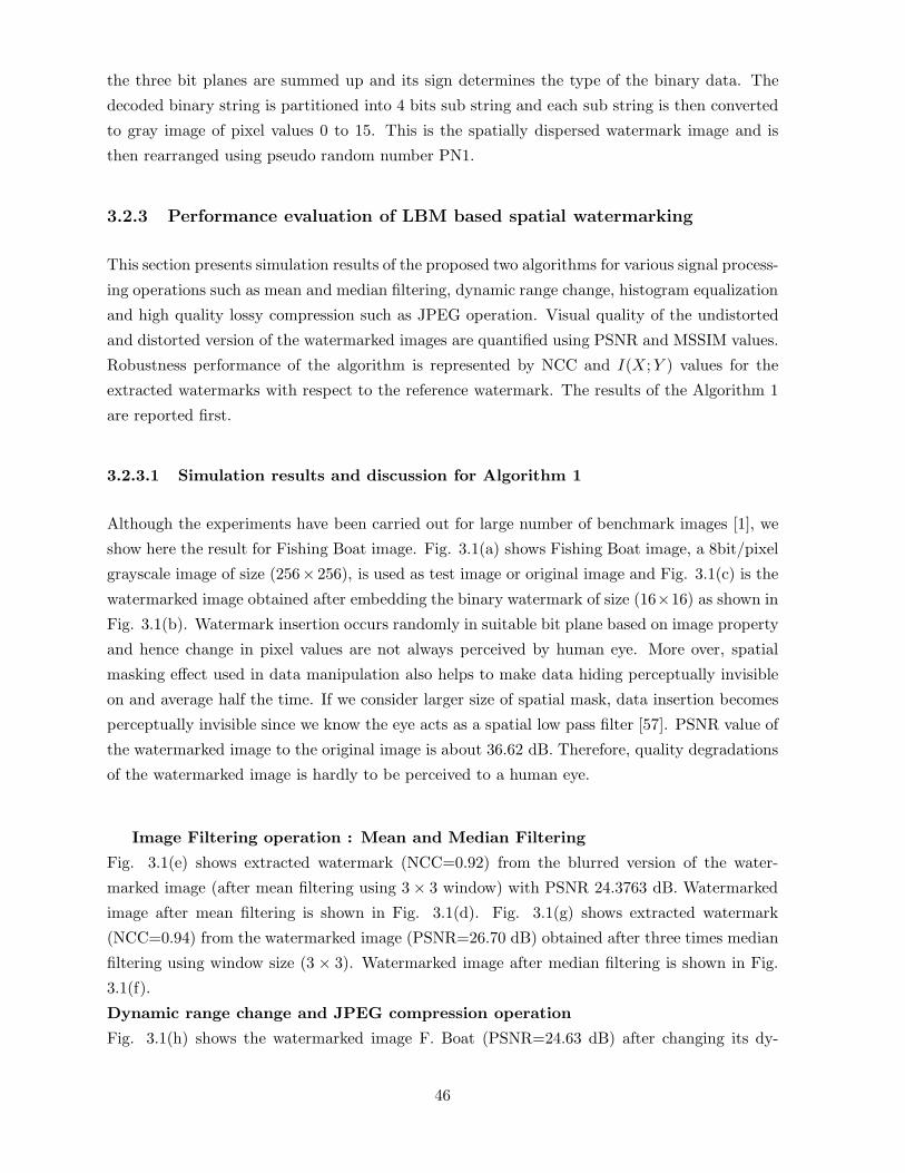
the three bit planes are summed up and its sign determines the type of the binary data. The
decoded binary string is partitioned into 4 bits sub string and each sub string is then converted
to gray image of pixel values 0 to 15. This is the spatially dispersed watermark image and is
then rearranged using pseudo random number PN1.
3.2.3 Performance evaluation of LBM based spatial watermarking
This section presents simulation results of the proposed two algorithms for various signal process-
ing operations such as mean and median filtering, dynamic range change, histogram equalization
and high quality lossy compression such as JPEG operation. Visual quality of the undistorted
and distorted version of the watermarked images are quantified using PSNR and MSSIM values.
Robustness performance of the algorithm is represented by NCC and I(X;Y ) values for the
extracted watermarks with respect to the reference watermark. The results of the Algorithm 1
are reported first.
3.2.3.1 Simulation results and discussion for Algorithm 1
Although the experiments have been carried out for large number of benchmark images [1], we
show here the result for Fishing Boat image. Fig. 3.1(a) shows Fishing Boat image, a 8bit/pixel
grayscale image of size (256× 256), is used as test image or original image and Fig. 3.1(c) is the
watermarked image obtained after embedding the binary watermark of size (16×16) as shown in
Fig. 3.1(b). Watermark insertion occurs randomly in suitable bit plane based on image property
and hence change in pixel values are not always perceived by human eye. More over, spatial
masking effect used in data manipulation also helps to make data hiding perceptually invisible
on and average half the time. If we consider larger size of spatial mask, data insertion becomes
perceptually invisible since we know the eye acts as a spatial low pass filter [57]. PSNR value of
the watermarked image to the original image is about 36.62 dB. Therefore, quality degradations
of the watermarked image is hardly to be perceived to a human eye.
Image Filtering operation : Mean and Median Filtering
Fig. 3.1(e) shows extracted watermark (NCC=0.92) from the blurred version of the water-
marked image (after mean filtering using 3 × 3 window) with PSNR 24.3763 dB. Watermarked
image after mean filtering is shown in Fig. 3.1(d). Fig. 3.1(g) shows extracted watermark
(NCC=0.94) from the watermarked image (PSNR=26.70 dB) obtained after three times median
filtering using window size (3 × 3). Watermarked image after median filtering is shown in Fig.
3.1(f).
Dynamic range change and JPEG compression operation
Fig. 3.1(h) shows the watermarked image F. Boat (PSNR=24.63 dB) after changing its dy-
46

namic range from 255-1 to 200-50. Extracted watermark symbol is shown in Fig. 3.1(i) with
NCC=0.97. The similar experimentation is done for all other watermarked images and robust-
ness performance has been checked. Fig. 3.1(k) shows the extracted watermark (NCC=0.83)
from JPEG compressed version of the watermarked image (PSNR=28.73 dB ) with quality fac-
tor 80. Fig. 3.1(j) shows the watermarked image after such JPEG compression operation. As
compression ratio increases, NCC value of the extracted watermark decreases and watermark
will be destroyed and become indiscernible.
Figure 3.1: (a): Original image (Fishing Boat), (b): Watermark image, (c): Watermarked Image,
(d): Watermarked image after mean filtering, (e): Extracted watermark from (d), (f): Water-
marked image after median filtering, (g): Extracted watermark from (f), (h): Watermarked
image after change in dynamic range, (i): Extracted watermark from (h), (j): Watermarked im-
age after JPEG compression, (k): Extracted watermark from (j), (l): Watermarked image after
LSB(s) manipulation, (m): Extracted watermark from (l), (n): Watermarked image after image
sharpening, (o): Extracted watermark from (n), (p): Watermarked image after noise addition,
(q): Extracted watermark from (p)
Deliberate Least Significant Bits manipulation :
Least Significant bit(s) for all pixels or randomly selected pixels of the watermarked image is ma-
47

nipulated and extracted watermark is still recognizable to a certain degree of bit manipulation.
Fig. 3.1(l) shows the watermarked image (with PSNR=35.45 dB) obtained after complementing
two least significant bits of the randomly selected pixels and Fig. 3.1(m) shows the correspond-
ing extracted watermark with NCC=0.76.
Image sharpening and noise addition :
Fig. 3.1(n) shows the watermarked image (with PSNR=19.56 dB) obtained after image sharp-
ening operation and Fig. 3.1(o) shows the extracted watermark with NCC=0.92. Robustness
of the algorithm against noise addition is also tested. The gray values for the 10% randomly
selected pixels are changed by 10%. Fig. 3.1(p) shows one such image with PSNR=28.75 dB
and Fig. 3.1(q) shows the extracted watermark with NCC=0.76.
3.2.3.2 Simulation results and discussion for Algorithm 2
Fig. 3.2 (a) shows a test image Fishing Boat and Fig. 3.2(c) is the watermarked image using
watermark image shown in Fig. 3.2 (b). PSNR between the watermarked image and the original
image is about 38.24 dB and security value is 0.05322. Imperceptibility and security measures
of the hidden data for test images F. Boat, Bear, Lena and Opera are shown in Table 3.1.
Table 3.1: Imperceptibility and security values of the hidden data; columns number 2 and 3
indicate results for the proposed algorithm 2 and 4 and 5 for the proposed algorithm 1
Test PSNR Security PSNR Security
Image (dB) (ε) − value (dB) (ε) − value
Lena 36.23 0.0546 35.87 0.0562
F. Boat 38.24 0.0532 36.62 0.0545
Bear 36.74 0.0562 37.12 0.0523
Opera 37.39 0.0568 37.23 o.0532
Mean and median filtering:
Fig. 3.2(d) shows the blurred version of the watermarked image and is obtained using (3 × 3)
window. PSNR value of this image is 24.78 dB. Fig. 3.2(e) shows the extracted watermark
with I(X;Y)=0.57. Fig. 3.2(g) shows extracted watermark image with I(X;Y)=0.60 from the
distorted watermarked image obtained after median filtering. Median filtered version of water-
marked image is shown in Fig. 3.2(f) and its PSNR value is 26.56 dB. Image shown in Fig.
3.2(f) is found after two times successive filtering operation using (3 × 3) window. Results of
mean and median filtering are reported in Table 3.2.
Dynamic range change and JPEG compression operation
Fig. 3.2(h) shows the watermarked image F. Boat (PSNR=24.63 dB) after changing its dy-
48

Table 3.2: Robustness results after mean (2nd, 3rd and 4th column) and median filtering (5th,
6th and 7th column)
Test PSNR Pe1 I(X;Y ) PSNR Pe1 I(X;Y )
Image (dB) Pe2 value (dB) Pe2 value
Lena 23.24 0.05;0.15 0.53 25.5 0.03;0.12 0.57
F. Boat 24.78 0.03;0.14 0.57 26.56 0.01;0.11 0.60
Bear 25.32 0.04;0.14 0.61 26.45 0.02;0.11 0.56
Opera 25.56 0.02;0.12 0.53 26.75 0.03;0.14 0.56
namic range from 255-1 to 200-50. Extracted watermark symbol is shown in Fig. 3.2(i) with
I(X;Y)=0.52. The similar experimentation is done for all other watermarked images and robust-
ness performance has been checked. Fig. 3.2(k) shows the watermark with I(X;Y)=0.46 and
is extracted from the watermarked image obtained after JPEG compression (PSNR=27.33dB)
with quality factor 70. The compressed watermarked image is shown in Fig. 3.2(j). Results
reported in Table 3.3 indicates resiliency against dynamic range change in gray values and JPEG
compression.
Table 3.3: Robustness results against dynamic range change (2nd, 3rd and 4th column) and
JPEG compression (5th, 6th and 7th column)with quality factor at 70
Test PSNR Pe1 I(X;Y ) PSNR Pe1 I(X;Y )
Image (dB) Pe2 value (dB) Pe2 value
Lena 23.45 0.03;0.13 0.52 27.32 0.06;0.16 0.48
F. Boat 24.63 0.02;0.12 0.52 27.33 0.06;0.18 0.46
Bear 23.64 0.04;0.14 0.61 26.45 0.02;0.11 0.56
Opera 25.56 0.02;0.12 0.53 27.23 0.04;0.15 0.47
Deliberate Least Significant Bits manipulation :
Fig. 3.2(l) shows the distorted version of the watermarked image F. Boat (PSNR=36.23dB)
obtained by simultaneously complimenting three least significant bits of all pixels in the water-
marked image. The extracted watermark symbol is shown in Fig. 3.2 (m) with I(X;Y) value of
0.64.
Image sharpening and noise addition
Fig. 3.2(n) shows the watermarked image Fishing Boat (PSNR=22.56dB) obtained after image
sharpening operation and the extracted watermark symbol is shown in Fig. 3.2(o) whose I(X;Y)
value is 0.49. Fig. 3.2(p) shows noisy watermarked image (PSNR=32.35dB) obtained after
changing the gray value by 10 %, of 10 % randomly selected pixels of the watermarked image.
The extracted watermark symbol is shown in Fig. 3.2 (q) with I(X;Y)=0.54. Results reported
49

in Table 3.4 show the robustness performance against image sharpening and noise addition op-
erations.
Table 3.4: Robustness results against image sharpening operation (2nd, 3rd and 4th column)
and noise addition
Test PSNR Pe1 I(X;Y ) PSNR Pe1 I(X;Y )
Image (dB) Pe2 value (dB) Pe2 value
Lena 21.36 0.06;0.16 0.54 31.37 0.04;0.15 0.54
F. Boat 22.56 0.04;0.14 0.56 32.35 0.02;0.11 0.52
Bear 22.74 0.05;0.15 0.51 31.73 0.04;0.15 0.51
Opera 21.49 0.04;0.15 0.53 30.85 0.02;0.12 0.53
50

Figure 3.2: (a) Original image; (b) Watermark image; (c) Watermarked Image; (d) Water-
marked image after mean filtering; (e) Extracted watermark from (d); (f) Watermarked image
after median filtering; (g) Extracted watermark from (f); (h) Watermarked image after change in
dynamic range; (i) Extracted watermark from (h), (j) Watermarked image after JPEG compres-
sion; (k) Extracted watermark from (j), (l) Watermarked image after LSB(s) manipulation; (m)
Extracted watermark from (l); (n) Watermarked image after image sharpening; (o) Extracted
watermark from (n); (p) Watermarked image after noise addition; (q) Extracted watermark
from (p)
We compare the performance of the proposed two watermarking algorithms with the work
done by chan et al. [63]. Chan’s work focuses on imperceptibility improvement without consid-
ering robustness performance. Robustness performance of our methods against various signal
processing operations are much better compared to [63]. Data imperceptibility of [63] is some-
times better than our methods. But the novelty of our methods lie in imperceptibility improve-
ment without any extra computational complexity unlike [63]. In fact computation cost for the
proposed two algorithms presented here are significantly low. Simpler implementation leads to
the hardware realization possible and makes the algorithms suitable for realtime applications
of authentication and integrity verification. In the following subsection we describe hardware
design for the algorithm 2.
51

3.2.4 Hardware design[172]
The hardware design for the spatial domain data embedding in digital images is divided in two
main parts, watermark embedding and watermark decoding[172].
Figure 3.3: VLSI architecture of watermark embedding
3.2.4.1 Design of Watermark embedding unit
Fig. 3.3 shows VLSI architecture of watermark embedding section. The major sub blocks in
this section are bit select unit, message extension unit, control unit, and bit insertion unit.
Bit select Unit selects bit plane for data embedding (using the ST [0:3] bus), and allows message
bit to flow into the embedding unit at the desired time (acting as the MUX control input). The
required components for the unit are three (3) T flip-flops (FF), one (1) 3 to 8 line decoder, one
(1) 8 to 1 line MUX, three (3) inverters. Fig. 3.4 shows the circuit design of bit select unit.
Message extension unit transforms 4-bits of one pixel value of the message signal to 16 bits
by adding redundancy. Fig. 3.5 shows the circuit design of the message extension unit. At the
beginning of embedding cycle (when 1 pixel value of the message is completely embedded), 4 bits
are loaded into a 4-bit parallel-in-serial out (PISO) shift register. The output is taken from FF
in which 4-th bit of the message pixel is initially loaded. A binary counter that counts from 0-15
and a logic circuit together control the operation when the bits will be shifted in the register.
First CLOCK ENABLE (CE) signal comes from the control unit when the counter has counted
52
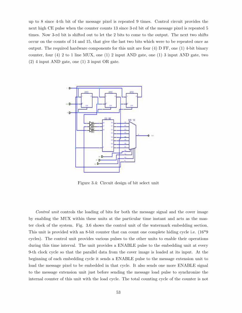
up to 8 since 4-th bit of the message pixel is repeated 9 times. Control circuit provides the
next high CE pulse when the counter counts 13 since 3-rd bit of the message pixel is repeated 5
times. Now 3-rd bit is shifted out to let the 2 bits to come to the output. The next two shifts
occur on the counts of 14 and 15, that give the last two bits which were to be repeated once as
output. The required hardware components for this unit are four (4) D FF, one (1) 4-bit binary
counter, four (4) 2 to 1 line MUX, one (1) 2 input AND gate, one (1) 3 input AND gate, two
(2) 4 input AND gate, one (1) 3 input OR gate.
Figure 3.4: Circuit design of bit select unit
Control unit controls the loading of bits for both the message signal and the cover image
by enabling the MUX within these units at the particular time instant and acts as the mas-
ter clock of the system. Fig. 3.6 shows the control unit of the watermark embedding section.
This unit is provided with an 8-bit counter that can count one complete hiding cycle i.e. (16*9
cycles). The control unit provides various pulses to the other units to enable their operations
during this time interval. The unit provides a ENABLE pulse to the embedding unit at every
9-th clock cycle so that the parallel data from the cover image is loaded at its input. At the
beginning of each embedding cycle it sends a ENABLE pulse to the message extension unit to
load the message pixel to be embedded in that cycle. It also sends one more ENABLE signal
to the message extension unit just before sending the message load pulse to synchronize the
internal counter of this unit with the load cycle. The total counting cycle of the counter is not
53

required for the operation. So after a message pixel value is embedded, the counter is reset
so that it can start afresh for a new embedding cycle. The required hardware components are
one (1) D FF, one (1) 8-bit binary counter, eleven (11) inverter, two (2) 2 input AND gates,
four (4) 2 input XOR gate, six (6) 2 input XNOR gates, one (1) 4 input AND gates, two (2)
5 input AND gates, one (1) 2 input OR gate, one (1) 8 input OR gate, two (2) 8 input NOR gate.
Figure 3.5: Circuit design of message extension unit
Bit insertion unit inserts the message bits after getting from the message extension unit in
the bit plane of the cover image as specified by the bit select unit. Fig. 3.7 shows hardware
design of data insertion unit. It consists of an 8-bit loadable shift register (SR) with feedback of
the 4-th bit to the serial unit. Image bits are loaded in parallel at every 9-th clock cycle as guided
by the control unit. For the next 8 cycles, the bits are shifted across register with the message
bit being loaded into the register at time indicated by the bit select unit. This bit replaces a
particular image bit and continue shifting through the SR. One full rotation is complete after 8
clock cycles. The image bits return to their original positions after the message bit inserted in
the specified position. The embedded bit is taken out in parallel- simultaneously the next pixel
bits of the cover image are loaded into the unit. The required hardware components are eight
54

Figure 3.6: Circuit design of control unit at watermark embedding section
(8) D FF, and eight (8) 2 to 1 line MUX.
Figure 3.7: Circuit design of bit insertion unit
3.2.4.2 Design of watermark decoding unit
Fig. 3.8 shows hardware design of the watermark decoding section. The major sub blocks in
this section are Bit extraction unit, Decision making unit, and message formation unit.
In bit extraction unit, message bit was extracted from the proper bit (where message bit was
55

embedded) of the 8-bit data. The data is loaded into 8-bit parallel -in-parallel out register and
the proper bit is taken from the output of a 8:1 multiplexer. The required hardware components
are 8-bit loadable register, 8 to 1 multiplexer.
In decision making unit, the redundancy is removed (the redundancy was incorporated at
Figure 3.8: Circuit design of watermark decoding unit
the transmitting side) from the data sequence obtained from bit extraction unit. Thus 4-bit
message pixel is formed from the 16 bit extracted data. One 4 bit counter is used to count how
many 1’s have been received from the first 9 received bits, the other 4-bit counter will count the
same from the next 5 bits. One 2 to 4 decoder is used to select which counter will be enabled
at what time. Thus the decoder select input is taken from a logic circuit that will generate 00
for first 9 clock cycle, 01 for neat 5 clock cycle, 10 and 11 for the next two. The decoder input
comes from the previous stage. The required hardware components are one (1) 2 to 4 decoder,
three (3) 4-bit binary counters, and six (6) 2-input OR gates, two (2) 2-input AND gates, five
(5) 3-input AND gates (having one or two inverted inputs), four (4) 4-input AND gates (having
one or two inverted inputs), and XOR gate.
Formation of watermark message: Each message pixel consists of 4-bits and bits are stored
in serial in parallel out shift register. One 4 to 1 MUX is used for storing the proper bit at
proper time. The respective bit is stored at proper time serially into the shift register by proper
controlling the MUX input. A D flip-flop is used for resetting the shift register at proper time
instant. CE (clock enable) terminal is controlled by some logic circuit for controlled loading
56

of the register. The required hardware components are one (1) 4 to 1 MUX, one (1) serial in
parallel out shift register, 1 D flip-flop, one (1) 4 input OR gate.
The hardware design is implemented using XILINX SPARTAN series FPGA. The chip used is
XCS05 which contains 100 CLB (configurable logic block), out of which 95 CLBs are consumed,
40 for watermark embedding unit and 45 for the watermark decoding unit.
Although spatial domain embedding methods have merit of simple implementation, but their
usages are restricted due to their poor robustness performance. Robustness performance may
be enhanced by exploiting image characteristics during data embedding. We use image charac-
teristics such as variance of the blocks, average image information, average image information
and edge information of the blocks.
3.3 LBM based watermarking using image characteristics[154,
153, 166]
In this section we present three block based simple LBM watermarking processes (we call them
as Method 1, Method 2 and Method 3 ) where watermark information is inserted in suitable
lower order bit plane of the average brightness value of the image block. Watermark insertion
and extraction processes are exactly identical in all three cases except for difference in selection
of embedding regions. The cover image is partitioned into non-overlapping square blocks of size
(8×8) pixels. A block is denoted by the location of its starting pixel (x, y). If the cover image is
of size (N ×N), total (N/8×N/8) number of such blocks are obtained for watermark insertion.
The selection of embedding regions are discussed briefly as follows.
3.3.1 Method 1: Selection of blocks based on variance values
The variance for pixel values of each block is calculated and the values are arranged in ascending
order. The variance (σ2) of a block of size (m× n) is denoted by
σ2 =1mn
m−1∑x=0
n−1∑y=0
[f(x, y) − µ]2 (3.1)
where
µ =1mn
m−1∑x=0
n−1∑y=0
f(x, y) (3.2)
is the statistical average value of the block.
57

Variance is considered as image characteristics to choose selection of embedding regions
as it is found (in the section of image visual quality of the preceding chapter, section 2.4.1)
that change in variance due to signal addition has an important role to quantify visual quality
of the watermarked image. The blocks having small variance may be called as homogenous
blocks, where the relative smallness in variance depends on the characteristics of image to be
watermarked. If the watermark symbol is a (N ×N) binary image, only N2 homogenous blocks
are sufficient to insert one watermark pixel in each such homogenous block.
3.3.2 Method 2: Selection of blocks based on average image information
Watermark embedding regions can also be selected on the basis of average information or entropy
of pixel intensities. Entropy values are used because information about an image is captured
not from the single pixel alone but from the pixel and its neighborhood, since a strong two
dimensional (2D) spatial correlation exists among the neighboring pixels in most of the natu-
ral images. If data-embedding process creates a noticeable change in spatial correlation, the
imperceptibility requirement of watermarking will not be fulfilled. One of the good measures
of spatial correlation among the neighboring pixels is the average information value. In Shan-
non’s entropy measure [247], the signal is considered as a long sequence of symbols and entropy
value depends on the relative occurrence of symbols irrespective of their position of occurrence.
But digital image being a two dimensional sequence of highly correlated pixel values, average
information or entropy of image (or sub image) not only depends on the relative occurrence of
the pixel values but also depends on their positions of occurrence. It has been shown in [202]
that exponential form of entropy function can capture pictorial information better compared to
conventional Shannonian entropy. The authors of [202] defined the entropy of an image block
n = (a× a) (where n = a2 are the number of signal points) in the form
H =i=n∑i=0
pieui =
i=n∑i=0
pie1−pi (3.3)
Where ui = (1 − pi) is the ignorance or uncertainty of pixel value.
The blocks with the smallest and the largest N2 average information values are termed as low
and high informative blocks. The other N2 blocks corresponding to the entropy values within
the range [(M2/(p2 ∗ 2)]-N2/2 to [(M2/(p2 ∗ 2)]+N2/2 in ascending order are called medium
informative blocks. The rational behind the choice of medium informative block as embedding
region is due to the fact that data embedding in low informative block is easily perceived by
the human eye while data embedding in the high informative blocks will be lost due to the
quantization operation of lossy compression operation. So it is expected that choice of medium
informative blocks will make a good trade-off between these two.
58

3.3.3 Method 3: Selection of blocks based on average image information and
average edge entropy
In the foregoing subsection, we select blocks on the basis of average information of the image
block. However, for a natural image, a sub image with particular entropy value may represent
a smooth, noisy or edgy region (This is shown pictorially in the next chapter). Edge is an
important image feature which carries major image information. It is expected that during
modification of the cover image for watermark embedding, minimum number of edge points
should get modified so that imperceptibility and robustness are fulfilled simultaneously. So
watermark embedding blocks can be selected on the basis of both average image information as
well as edge information of the blocks.
To calculate the average edge information i.e. edge entropy of the block, first the edge map
is calculated using the conventional gradient operator. The edginess or the strength of edge of
a pixel automatically considers the effect of neighborhood pixel values, so the measure of edge
entropy of sub image is dependent on the relative occurrence of these edge strength irrespective
of their position. This supports the usage of Shannon’s form of entropy to calculate the average
edge information of each block. According to Shannon’s definition, the entropy of an n-elements
set is
H = −n∑
i=1
pi logpi (3.4)
where pi is the probability of occurrence of the event “i” with 0 ≤ pi ≤ 1 and∑n
i=1pi=1 [247].
We now summarize the criteria for selection of blocks as follows:
(1) The average information of each block is calculated using the Equation (3.3).
(2) The edge map is calculated using the conventional gradient edge detector. Now, from the
edge map, the average edge information in each block is calculated using Equation (3.4).
(3) The two measure of entropy thus obtained for each block is then summed up and the
values thus obtained are sorted in ascending order. The lower portion of the ascending order
arrangement should be chosen to make a good trade-off between image imperceptibility and
robustness to signal processing operation.
3.3.4 How to embed watermark bit
Although the flexibility of point processing operation in spatial domain embedding offers greater
control on visual distortion as well as higher embedding capacity but at the same time it is
the primary cause of fragileness against signal processing operations. Under such situation it
is logical to embed each watermark bit to a group of pixels within a block so that some of
the bits remain intact even after signal processing operations. However, if a watermark bit is
embedded independently in all the pixel values of the block using bit substitution method, the
59

pixel values will remain unchanged or increased (decreased) based on the match or nature of
mismatch between the watermark bit and bits to be replaced. So the overall effect is the change
in variance or average information of the pixel values before and after embedding. This leads
to wrong detection of watermark bit even if watermarked image undergoes small distortion.
This problem may possibly be overcome if multiple pixels values are considered collectively
for embedding each watermark bit. Thus we may think of embedding a watermark bit by
substituting a suitable bit of the average brightness value i.e. statistical average value of the
pixels.
3.4 Watermark embedding and extraction
We consider a grayscale monochrome image as cover signal and a binary image as watermark
signal.
3.4.1 Watermark embedding
Different steps of watermark embedding are described as follows:
Step 1: Selection of blocks
The required M2 number of blocks are selected for each method as described earlier. A two
level map of size (N/8 × N/8) is constructed assigning each selected block of the cover image
by value ‘1’ while all other blocks by value ‘0’.
Step 2: Spatial dispersion of watermark
In all three methods, one watermark pixel is inserted in each selcetd block. Before insertion, the
binary watermark is spatially dispersed using a pseudo random number of suitable length [250].
Step 3: Watermark insertion
From the two level image formed in step 1, desired blocks of the cover image are selected and
mean value of the pixels for each such block is used for watermark insertion. Let for one such
block this average value and its integer part are denoted by A and A = A respectively. Now one
pixel from spatially dispersed watermark replaces a particular bit (preferably Least Significant
Bit planes) in bit plane representation of A.
A multilevel secret image is constructed by inserting the value of bit position selected for
different homogenous block located in the ‘1’ position of the secret image. This positional infor-
mation as gray value of the secret image helps to extract watermark pixel from the proper bit
60

position of the mean gray value of the block.
Step 4: Adaptive bit manipulation
Adaptive bit manipulation, similar to the process discussed in section 3.2.1.1 or 3.2.2.1, is done
to protect watermark bit from primitive nondestructive operations.
3.4.2 Watermark Extraction
The extraction of watermark requires the secret image(s) and the key (k) used for spatial disper-
sion of the watermark image. The mean pixel value for each selected block of the watermarked
image/distorted watermarked image is calculated and watermark pixels are extracted.
The spatially dispersed watermark image thus obtained is once again permuted using the
same key (k) (pseudo random number) and watermark in original form is thus obtained. This
completes watermark extraction process.
3.5 Performance evaluation of block based LBM methods
Table 3.5 shows the relative performance of data imperceptibility and security of the hidden
data for all three methods. It is found that Method 2 shows the best result for visual invisibility
of the hidden data while Method 1 shows the lowest performance for the same.
Table 3.5: Imperceptibility and security value of the hidden data for Methods 1, 2, 3
Test PSNR Security PSNR Security PSNR Security
Image in (dB) ε-value in (dB) ε-value in (dB) ε-value
Meth.1 Meth. 1 Meth. 2 Meth. 2 Meth. 3 Meth. 3
Fishing Boat 35.23 0.19242 39.23 0.01724 36.78 0.05312
Bear 35.76 0.163 39.43 0.01986 36.23 0.06154
New York 34.38 0.168 38.67 0.02125 37.56 0.0692
Opera 35.12 0.154 37.75 0.01856 37.43 0.0754
Lena 36.34 0.168 38.23 0.02067 36.34 0.0602
Pill 35.67 0.172 39.21 0.01925 37.25 0.0675
Table 3.6 shows the robustness performance of the all three methods against various signal
processing operations. The numerical values in Table 3.6 which represent PSNR and NCC are
61

computed by averaging over large number of test images.
Table 3.6: Robustness performance against various signal processing operations
Test PSNR NCC PSNR NCC PSNR NCC
Image in (dB) value in (dB) value in (dB) value
Meth.1 Meth. 1 Meth. 2 Meth. 2 Meth. 3 Meth. 3
Mean filtering 24.23 0.73 24.31 0.76 24.54 0.84
Median filtering 25.76 0.74 25.21 0.79 36.23 0.88
Gaussian filtering 24.38 0.74 38.67 0.78 37.56 0.82
Rescaling 21.23 0.72 21.23 0.77 37.43 0.83
JPEG compression 27.23 0.70 26.83 0.72 36.34 0.75
Noise addition 31.23 0.80 32.21 0.81 32.25 0.84
We test robustness performance of the all three methods for various signal processing oper-
ations ranging from mean, median, Gaussian filtering, noise addition, cropping, to lossy com-
pression and image rescaling operations. It is found that Method 3 shows expectedly the best
robustness performance as average image information and edge entropy of the block are jointly
used as image features for selecting the embedding regions. Following the similar argument,
it can be easily explained why Method 2 shows better robustness performance compared to
Method 1. Robustness performance of the Method 3 is reported in Fig. 3.9. Figs. 3.9 (a)-(t)
show watermarked images Lena after various signal processing operations along with the ex-
tracted watermark images in all cases. Robustness performance of all three methods against
lossy JPEG compression are not much satisfactory even at high quality image. This is, in
general, true for all spatial domain embedding methods. The results reported for JPEG com-
pression correspond to quality factor 70. We simulate image cropping operation by forcefully
making gray values zero for the pixels of twenty rows and columns on both sides of the cover
image. However, extracted watermarks show their visual recognizability and methods show their
robustness against cropping operation.
Although robustness performance of the proposed methods have been tested for common sig-
nal processing operations but all three methods fail to show their robustness performance when
degree of signal distortion are increased. Robustness performance is quite poor for other signal
processing operations such as histogram equalization, lossy JPEG 2000, collusion operation and
other typical operations found in Checkmark package [227]. Moreover payload capacity is also
62

not satisfactory.
Figure 3.9: (a) Cover image Lena; (b)Watermarked image; (c) Watermarked image after mean
filtering using (3 × 3) window; (d) Watermarked image after symmetric cropping; (e): Water-
marked image after median filtering using (3 × 3) mask twice; (f): Watermarked image after
rescaling; (g) Watermarked image after JPEG Compression (at Quality factor 70); (h) Water-
marked image after noise addition; (i) Watermark image; (j) Extracted watermark after mean
filtering on watermarked image; (k) Extracted watermark after cropping operation applied on
watermarked image; (l) Extracted watermark after median filtering on watermarked image; (m)
Extracted watermark after rescaling operation on the watermarked image (n) Extracted water-
mark after JPEG compression; (o) Extracted watermark after noise addition on watermarked
image; (p) Cover image Fishing boat; (q) Cover image Pills; (r) Cover image Black bear; (s)Cover
image New York; (t) Cover image opera
3.6 Additive watermarking for optimal invisibility
Robustness performance may be improved too some extent by adopting additive embedding
method. According to Equation (1.4), the image fidelity is degraded with the increase in pay-
63

load capacity and embedding strength. But the higher value of embedding strength increases
reliability of decoding, of course, at the cost of greater visual distortion. Thus imperceptibility-
robustness-capacity requirement form a multidimensional nonlinear problem of conflicting na-
ture. Genetic algorithm (GA), like an efficient search for optimal solutions [102, 185, 113] in
many image processing and pattern recognition problems [203], can also be used in this topic of
research but in reality the usage of the tool has been explored very little.
In this thesis we use Genetic Algorithm (GA) as optimization tool in spatial domain wa-
termarking and develop two watermarking algorithms (i) for improved detection [171] and (ii)
improved imperceptibility [170].
In the following section we describe these algorithms one after another along with their
performance results.
3.6.1 Algorithm1:GA for improvement in detection of hidden data[170]
In light of Equation (1.6), it is possible to meet visual imperceptibility and robustness simulta-
neously if the watermark signal is mapped to a suitable form and is embedded to the cover. A
region for data embedding is selected in such a way so that maximum number pixel values of the
cover image differ from the message pixel values by less than a predefined threshold and a dif-
ference signal (D) is formed. The difference signal is now added with higher embedding strength
compared to the strength required for direct embedding of the original watermark signal for a
specified limit in visual distortion of the cover. Decoding of message needs the regeneration of
difference signal and the inverse process will extract the message signal. The reliability of the
decoding process depends on how faithfully the difference signal is regenerated.
The above problem can be stated mathematically as follows: Given an M-point difference sig-
nal (D), how an approximate signal (D′) be generated using N - signal points where N �M and
(D′) is close resemblance of (D). There may be one method to regenerate better approximation
signal using higher order interpolation but in that case computation cost increases exponentially
with order of interpolation. Linear interpolation is a good compromise between the computa-
tion cost and better approximation for the regenerated signal. In such case, it is the important
point to find which N -points would generate better approximation and how N -values affect this
approximation function. This can be thought as an optimization problem and GA provides an
optimal solution.
3.6.1.1 Proposed data hiding algorithm
The total process of data embedding and decoding consists of three stages. These are Stage
1: Selection of data embedding regions and formation of difference matrix followed by data
64

embedding, Stage 2: Generation of set of points using GA to optimally represent the difference
matrix, Stage 3: Message retrieval.
Stage 1:Selection of data embedding regions and formation of difference matrix followed by
data embedding
The choice of cover images plays an important role for achieving imperceptibility of the hidden
data. Images with a low number of colors, computer art, with a unique semantic content, such
as fonts, should be avoided. Some data hiding experts recommend grayscale images as the
best cover-images. We consider gray scale image as cover and the similar type image like text
information as message signal. Steps for the selection of embedding region are as follows.
Step 1 : Input gray scale images used both as cover and message signal.
Step 2: Setting of an appreciable percentage for matching criteria (at least 80%)
Step 3 : Selection of a region from the cover equal in the size to that of message signal.
Step 4 : Comparison of variation of the pixel values between the cover and message signal.
Step 5 : Repetition of the above process by dynamically selecting windows all over the cover
image.
Step 6 : Once the Percentage matching criteria is satisfied, the process terminates, otherwise, it
is continued till the end of the cover image.
Step 7 : Output: (1) If percentage matching criteria is satisfied, then returns the Difference
Matrix to ensure a smooth image with little variations. (2) If no matching region is found,
returns a null matrix denoting failure of finding the specified percentage matching region.
The difference matrix (D) is then multiplied by proper embedding strength (K), and added
to the respective pixel values of the cover image (C). The watermarked image can be obtained
as follows:
S = C +K.D (3.5)
Stage 2:Generation of set of points using GA for optimal representation of the difference
matrix
The main objective is to find an optimal set of points using GA so that an approximate version of
difference signal can be generated. The operation of GA depends on initial population, crossover
and mutation. According to De Jong’s elitist model [126], the best fit string obtained is included
in the new population to preserve the best structure in the population. The flowchart for the
stage is shown in Fig. 3.10. On each individual or the Population, 2-D interpolation technique is
applied to approximate the original matrix. The absolute mean error is evaluated by subtracting
the interpolated matrix from the difference matrix. The inverse of that absolute mean error is
considered to be the fitness value of that particular Individual.
65

Figure 3.10: Flow chart for generation of set of points using GA
C. Stage 3:Message retrieval
The final stage of the algorithm is the message retrieval process. The process needs the infor-
mation about the location within the watermarked image where watermark data in the form
of difference signal (D) is hidden. An approximate version (Dapp) of difference signal (D) is
obtained using linear interpolation technique among the N points grayscale values calculated
66

by Genetic Algorithm. The approximate cover image matrix Capp is then calculated using the
watermarked image S and Dapp as follows:
Capp = S −K.Dapp (3.6)
The message can be retrieved from the following relation:
L = Capp −Dapp (3.7)
where Dapp = K.D.
3.6.1.2 Performance evaluation
The efficiency of the proposed algorithm is tested by embedding the difference signal in several
cover images [1]. We select (256×256), 8-bit/pixel gray scale image as cover image and (64×64),
4-bits/pixel gray scale like image signal as watermark. PSNR value for the watermarked image
shown in Fig. 3.11(a) is 45.56 dB when embedding strength or modulation index value (K) is
set to 0.03. Fig. 3.11(b) shows the test watermark signal used for watermark casting. Similar
PSNR values are also found for the watermarked images when the algorithm is implemented for
other test images. PSNR value decreases to ∼ 41.33dB when K value is set to 0.3. This is quite
expected as higher index value causes much visual degradation of the cover image. The lower
embedding strength can indirectly be trade-off for good watermark detection by regenerating a
better approximation of the difference signal. As the number of generations i.e. iterations are
increased from 1000, 2000 to 2500, observation of Figs. 3.11(c), (d) and (e) reveal the fact that
the retrieved watermark images are becoming more and more close to the original images. This
is borne out by the property of GA which produces better solutions as the number of generations
are increased. The number of parameter values considered here are (10 × 10) for a difference
signal of size (64 × 64).
Figure 3.11: (a) Watermarked image; (b) watermark image; (c)-(e) retrieved messages after
1000, 2000 and 2500 iterations respectively
67
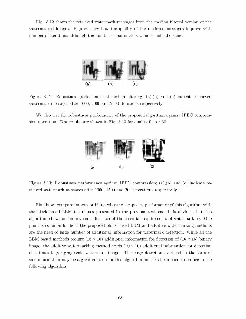
Fig. 3.12 shows the retrieved watermark messages from the median filtered version of the
watermarked images. Figures show how the quality of the retrieved messages improve with
number of iterations although the number of parameters value remain the same.
Figure 3.12: Robustness performance of median filtering; (a),(b) and (c) indicate retrieved
watermark messages after 1000, 2000 and 2500 iterations respectively
We also test the robustness performance of the proposed algorithm against JPEG compres-
sion operation. Test results are shown in Fig. 3.13 for quality factor 60.
Figure 3.13: Robustness performance against JPEG compression; (a),(b) and (c) indicate re-
trieved watermark messages after 1000, 1500 and 2000 iterations respectively
Finally we compare imperceptibility-robustness-capacity performance of this algorithm with
the block based LBM techniques presented in the previous sections. It is obvious that this
algorithm shows an improvement for each of the essential requirements of watermarking. One
point is common for both the proposed block based LBM and additive watermarking methods
are the need of large number of additional information for watermark detection. While all the
LBM based methods require (16 × 16) additional information for detection of (16 × 16) binary
image, the additive watermarking method needs (10 × 10) additional information for detection
of 4 times larger gray scale watermark image. The large detection overhead in the form of
side information may be a great concern for this algorithm and has been tried to reduce in the
following algorithm.
68

3.6.2 Algorithm 2:GA for optimal imperceptibility in data hiding[171]
In this algorithm we model digital watermarking problem as a conventional communication
process where watermark is considered as a message signal and cover signal is considered as
communication channel. GA is used to find two parameter values, namely reference amplitude
(A) and modulation index (µ) in linear and non linear transformation functions which are used
to modulate the auxiliary message. We choose a cover object that will hide the message properly
unlike the conventional watermarking application where the message must be hidden in the cover
work to which it refers. Lower and upper range of gray values are used for data hiding as the
characteristics of human visual system (HVS) are less sensitive to the change at these two ends.
3.6.2.1 Choice of modulation function
It is always logical to derive transformation function from the global or local (selected regions)
characteristics of the cover image to modulate the auxiliary message for optimal matching. Then
the transformation function would become image dependent and the associated parameters
are also not fixed. In order to have a general modulation function, we first use power-law
transformation X′= A(X + ε)µ where X and X
′denote the pixel value in auxiliary message
and the cover signal respectively. GA can be used for finding out the parameter values, namely
reference amplitude (A) and modulation index (µ), for optimal invisibility. Small values of
(µ) map large range of gray values into a narrow range so that X′
values lie inside a small
range surrounding A. We have to tune (A) and (µ) values in such a way that modulated
message will optimally match with the characteristics of embedding regions. We compared two
other transformation functions for their suitability on imperceptibility, security and robustness
issues of data embedding. One of the function is linear transformation function of the form
X′= A(1 + µX) and other one is parabolic function of the form X
′= A(1 + µ
√X). Although
the three transformation functions used are different in nature, but the associated parameters
are same A and µ. In the next section we discuss the calculation of these parameter values.
3.6.2.2 Calculation of parameters
In this section we discuss on how to calculate the range of the parameter values. We use power-
law transformation function in this analysis but the parameter values for other transformation
functions can also be calculated in the similar process.
Calculation of A
We have the modulation function as follows:
X′= A(X + ε)µ (3.8)
69

Differentiating X′w.r.t X, we get
dX′/dX = Aµ(X + ε)µ−1 (3.9)
Here dX′/dX is positive provided A > 0, µ > 0 and (X + ε) > 0, which implies X
′increases
monotonically with X. The upper (U′) and lower (L
′) bound of the modulated pixel values are
U′= Xmax
′= A(Xmax + ε)µ (3.10)
and
L′= Xmin
′= A(Xmin + ε)µ (3.11)
The range (Ψ) of the modulated pixel values is given as follows:
Ψ = U′ − L
′= A[(Xmax + ε)µ − (Xmin + ε)µ] (3.12)
The relation shows that for large A value, the span of the modulated pixel values (Ψ) will be
large leading to smaller probability of matching between the modulated message and embedding
regions. This in turn suggests to select lower value of A for better imperceptibility. The small
span (Ψ) is also possible for large A value provided very small value is selected for µ. But it is
shown in the detection process that small value of µ will make the auxiliary message vulnerable
to elimination in noisy transmission media. Similar argument also holds good for the value of
A. The value of A depends on selection of the auxiliary message as well as regions selected for
embedding. As rule of thumb A is selected as
A = X′mode/(Xmode + ε)µ (3.13)
where X′mode and Xmode respectively denote the mode of the gray values for the embedding
regions and the auxiliary messages. We can now specify deviation in reference amplitude on the
basis of allowable distortion in data embedding.
Calculation of µ
The value of µ determines the invisibility as well as the robustness of the hidden data. GA is
used to determine the µ value that results optimal imperceptibility while noise immunity value
is kept over a satisfactory level. Power-law transformation suggests if µ value is taken small
(µ < 1.0) keeping A constant, auxiliary message is mapped into a narrow range of gray values.
70

This fact is also supported by Equation (3.12). Confinement of gray values inside a narrow range
increases the probability of matching between the modulated message and the data embedding
region. But very small value of µ makes the detection of message impossible even after a very
small image distortion. The upper and lower value of µ are calculated as follows:
It is found thatX′is a monotonically increasing function ofX. The value of ε, acts as offset value
in image display, is set to (∼ 0.01). From Equation (3.8), we write X′max = A(255 + 0.01)µ =
A(255.01)µ
The maximum X value is taken 255 for monochrome gary level image. The corresponding µ
value is designated as µmax and is related with Xmax and A as follows: µmax � log X′max−log Alog 255
Similarly, µmin value can be written as follows:
µmin � log X′min−log A
log 0.01 = log A−log X′min
2.0
To have the positive value of µ, A should be within Xmax and Xmin which represents the
maximum and minimum gray values of the embedding regions respectively.
3.6.2.3 GA for data hiding
Let us consider here the problem of data embedding using these transformation functions. We
use the chromosomal representation of the parameter values, namely the reference amplitude
(A) and modulation index (µ) associated with the problems.
The simplest measure of closeness between the two pixels is the Eucidean distance. To quantify
this measure over sub image or image, we consider average Euclidean distance as fitness function.
The value of pay-off function can be expressed mathematically as follows:
F (A,µ) =∑N−1
i=0
∑N−1j=0 [Sij − eij(A,µ)]N2
(3.14)
where Sij is the gray value of (i, j)-th pixel of the embedding region, eij(A,µ) = A(Xij + c)µ, is
the gray value of (i, j)-th pixel of the message after modulation and N2 is the total number of
pixels in the embedding regions as well as in the auxiliary message.
Computation cost is low here since the number of parameters are less and simple transfor-
mation functions are used. Although the high mutation probability leads to exhaustive search
which may results in better imperceptibility at higher computation cost. Here moderate value of
mutation probability is chosen in order to achieve imperceptibility at comparatively lower cost.
The experimental conditions are depicted as follows:
(i) Size of the population is 20
(ii) Number of generations are 800
(iii) Probability of cross-over per generation is 0.95
(iv) Probability of mutation per bit is 0.005
71

3.6.2.4 Message recovery
The data embedding regions are selected from the watermarked image or its possibly distorted
version. Inverse transformation function is then applied by substituting the values of A and µ
used for data embedding. Inverse transformation function maps X′into X and thus message is
recovered.
(1) If power-law transformation, linear & parabolic functions are used for message modulation,
extracted messages can be represented respectively as follows:
X = (X′/A)
1/µ − ε (3.15)
X = (1/µA)(X′ −A) (3.16)
X = 1/(µA)2(X′ −A)2 (3.17)
Differentiating Equations (3.15),(3.16) and (3.17) with respect to X′
we get the following
equations respectively,
dX/dX′= (1/µ)(1/A)1/µ(X
′)1/µ−1 (3.18)
dX/dX′= 1/µA (3.19)
dX/dX′= 2(X
′ −A)/(µA)2 (3.20)
dX/dX′
denotes the change of X with respect to the change of X′
i.e. a measure of noise
immunity in the detection process. The large values of A and µ are preferable for reliable
decoding whereas small values of the same are desirable for better imperceptibility. Lower value
of dX/dX′indicates better reliability in detection process.
3.6.2.5 Performance evaluation and discussions
Tables 3.7, 3.8 and 3.9 show the effect of number of generations on imperceptibility and security
measures using power-law, linear and parabolic functions respectively. It is shown by the results
that rate of improvement in imperceptibility and security values for the parabolic functions
are faster than the linear function. The same is also true for the linear function compared to
power-law function.
Robustness efficiency against mean, median filtering and lossy compression are shown in
respective figures. Poor robustness in the case of power law function is supported by Equation
(3.18) where small values of A and µ causes change in X′
manifold even for the small change
72

Table 3.7: Effect of number of generation on imperceptibility and security measure using power-
law function
Generation PSNR ε I(X;Y )
number value (dB) value value
50 40.56 0.04625 0.2845
150 40.79 0.046124 0.2134
400 40.90 0.04135 0.2025
600 41.50 0.03984 0.1945
800 41.77 0.03834 0.1584
Table 3.8: Effect of number of generation on imperceptibility and security measure using linear
function
Generation PSNR ε I(X;Y )
number value (dB) value value
50 43.49 0.037136 0.4853
150 44.36 0.040018 0.4435
400 47.90 0.03653 0.4295
600 48.36 0.03066 0.3977
800 47.45 0.034230 0.4045
in X. Linear transformation function offers better imperceptibility as large range of message
gray values can be mapped to smaller range by choosing the small slope i.e. the product of
A and µ. At the same time better resiliency is achieved since dX/dX′
(Equation (3.19)) is no
way dependent on X′
although very small values of A and µ will affect the detection process.
Best data imperceptibility and security result is possible in case of parabolic function, as small
values of A and µ map wide range of message gray values to the narrow region in the lower
range of pixel values of the cover image. Detection reliability in such case is also satisfactory
since dX/dX′does not contain X
′with power term of A and µ like power law transformation
function, although small values of the parameters affect detection process little more compared
to linear transformation function. Table 3.10 shows the robustness performance of the proposed
algorithm against JPEG compression at quality factor 60. It is shown by the results that
extracted watermark fails to preserve its visual recognizability in case of power-law function
while the same is well maintained for the other two transformation functions.
73

Figure 3.14: (a) Cover image; (b), (c), (d) Watermarked images using power-law (PSNR=41.77
dB), parabolic function (PSNR=51.58 dB), linear function (PSNR= 47. 45 dB) respectively;
(e) Auxiliary message; (f), (g), (h) Extracted messages from (b), (c), (d) respectively; (i), (j),
(k) Extracted messages from mean filtered watermarked images when power law, parabolic &
linear functions are used respectively; (l), (m), (n) Extracted messages from median filtered
watermarked images when power law, parabolic, & linear functions are used respectively; (o),
(p) Extracted messages from compressed (JPEG) watermarked images (PSNR=31.06 dB) and
(PSNR=31.88 dB) using power law and linear function respectively.
74

Table 3.9: Effect of number of generation on imperceptibility and security measure using
parabolic function
Generation PSNR ε I(X;Y )
number value (dB) value value
50 45.42 0.037469 0.3825
150 46.74 0.037239 0.3964
400 48.73 0.036504 0.3453
600 50.37 0.025756 0.3534
800 51.53 0.023250 0.3245
Table 3.10: Robustness performance against JPEG compression at quality factor of 60
Function PSNR(dB) Visual I(X;Y )
Used compressed Recognition value
Power-law function 32.23 No 0.0945
linear function 31.88 Yes 0.2546
parabolic function 31.06 Yes 0.2344
75

3.7 Conclusions
In this chapter we have presented our studies on spatial domain digital watermarking using LBM
based technique and additive technique. LBM based techniques that use simple and variable
channel coding for watermark embedding are computationally efficient and easily implementable
through circuits. Thus the algorithms find applications for authentication and integrity verifi-
cation of digital data in real time environment. Poor robustness performance of the algorithms
have been improved in the block based LBM algorithms which use image characteristics such
as variance of the blocks, average image information, average image information and edge infor-
mation of the blocks.
In additive embedding, the usage of GA shows significant improvement in imperceptibility
of the hidden data along with high embedding capacity. The algorithms can be used for secured
communication of data through innocuous looking image. Experiment results show the effect of
number of generations on detection improvement in first algorithm while the same has shown
significant improvement in detection reliability as well as imperceptibility of the hidden data.
The major drawback of all the reported algorithms is poor robustness performance against
the varieties of valumetric distortions and the performance suffers with the increase of degree
of distortions. Robustness performance is significantly low for lossy JPEG and JPEG 2000
compression operations. This is due to the inherent property of the spatial domain embedding
and can be improved by embedding data using suitable image transformation. In the next
chapter, we concentrate on the improvement in robustness performance utilizing the properties
of transform domain.
76

Chapter 4
Transform Domain Watermarking
Technique
4.1 Introduction
It is observed that spatial domain watermarking methods, in general, are simpler to implement
but they are vulnerable to even small cover modifications. An attacker can simply apply signal
processing techniques in order to destroy the secret information entirely. In many cases even
the small changes resulting out of lossy compression operations yield to the total information
loss. It has been noted earlier that the embedding of watermark information in the frequency
domain is more robust than its spatial or time domain counterpart [119, 34, 95, 83]. This is
because transform domain methods hide messages in significant areas of the cover image leading
to robust watermarking and at the same time they remain imperceptible to the human sensory
system [81]. Most robust watermarking systems known today actually operates in some sort of
transform domain.
Many transforms such as DFT (discrete Fourier transform), Fourier-Mellin, DCT (discrete
cosine transform), wavelets etc. are used to decompose the cover signal [103, 124]. Transfor-
mation can be applied either over entire image, or to blocks throughout the image, or on other
variations. However, a trade-off exists between the amount of information added to the image
and the extent of robustness obtained. Many transform domain methods are independent of im-
age format and may survive conversion between lossless and lossy format. We describe different
transform domain spaces along with their properties in the context of digital watermarking.
77

4.2 Watermarking using Unitary Transformation
A digital image f(x, y) of size (N ×N) can be expressed in the form of a generalized transform
as [103, 124]
T (u, v) =N−1∑x=0
N−1∑y=0
f(x, y)g(x, y, u, v) (4.1)
where g(x, y, u, v) is the forward transformation kernel, and u and v have been digitized over
the range 0, 1, ...., N − 1.
Conversely, the image f(x, y) can be obtained by applying the inverse transform T (u, v) with
the help of the following relation
f(x, y) =N−1∑u=0
N−1∑v=0
T (u, v)h(x, y, u, v) (4.2)
where h(x, y, u, v) is the inverse transformation kernel with x and y values digitized over the range
0, 1, ....N − 1. The properties of the transformation kernel defined the attributes of respective
transforms.
4.2.1 Discrete Fourier Transform
Discrete Fourier Transform (DFT) being a widely used tool in signal processing for frequency
domain description of a digital signal [186], has been deployed in the field of watermarking for
its facility to control the frequencies of the host signal. Given a two-dimensional signal f(x, y)
of size (N ×N), the DFT is defined to be
F (u, v) = βN−1∑x=0
N−1∑y=0
f(x, y)e−(i.2.π.x.u/N−i.2.π.y.v/N) (4.3)
with β = (N.N)−1/2 and i =√−1. Furthermore, the inverse DFT (IDFT) is given by
f(x, y) = βN−1∑x=0
N−1∑y=0
F (u, v)e(i.2.π.x.u/N+i.2.π.y.v/N) (4.4)
DFT is useful for watermarking purposes as it offers phase modulation between the watermark
and its cover, in order to split images into perceptual bands etc.
4.2.2 Fourier-Mellin Transform
Most watermarking algorithms lack in robustness against affine geometric transformation. It is
often not possible to extract watermark after an affine geometric transformation applied to the
watermarked image. To overcome this weakness, Ruanaidh et al. [237] prescribed the use of
78

Fourier-Mellin transform for watermarking. The transform space of Fourier-Mellin is based on
the translation property of the Fourier transform.
f(x+ a, y + b) ⇔ F (u, v)e[−i(au+bv)] (4.5)
It is verified easily that only the phase is altered by this translation. Thus if the workspace
i.e the embedding domain is continued within the subspace defined by the amplitude of the
Fourier transform, the watermark extraction process will be insensitive to a spatial shift within
the picture. Let us consider the log-polar mapping (LPM) defined as follows:
(x, y) �→
x = eρ cos θ
with ρ ∈ R and θ ∈ [0, 2π]
y = eρ sin θ
(4.6)
Then the rotation of any element (x, y) in the cartesian coordinate system will result in a
translation in the logarithmic coordinate system [129]. In a similar way, a zoom will result in
a translation in the polar coordinate system. Utilizing this attributes of the coordinate system,
both rotation and zoom can be reduced to translation. Thus the feature of translation invariance
may be utilized to define a space insensitive to any rotation or zoom operations on transform
domain watermarked images.
4.2.3 Discrete Cosine Transform
The two-dimensional discrete cosine transform (DCT) is the heart of the most popular lossy
compression used today: JPEG for digital image and MPEG for digital videos [281, 209, 233].
Hence this transformation is a natural choice for design of compression resilient watermarking
algorithms. Given a two-dimensional signal f(x, y) of size (N ×N), the DCT is defined to be
F (u, v) =2NC(u)C(v)
N−1∑x=0
N−1∑y=0
f(x, y) cos(π.u(2x+ 1)
2N) cos (
π.v(2y + 1)2N
) (4.7)
where C(u) = C(v) = 1/√
2 when u = v = 0 v = 0 and C(u) = C(v) = 1 otherwise. The inverse
DCT (IDCT) is given by
f(x, y) =2N
N−1∑u=0
N−1∑v=0
C(u)C(v)F (u, v) cos(π.u(2x+ 1)
2N) cos (
π.v(2y + 1)2N
) (4.8)
Some of the arguments in favor of using DCT in watermarking are stated here. Embedding rules
operating in the DCT domain are usually more robust to JPEG and MPEG compression; thus
the watermark designer can prevent JPEG/MPEG attacks more easily. Furthermore, results
of studies on models of human visual system (HVS) [291, 290] may be applied to limit visual
distortion within tolerable range during watermark embedding. Last but not least, watermarking
in the DCT domain offers the possibility of directly realizing the embedding operation in the
79

compressed domain (i.e inside a JPEG or MPEG encoder) in order to minimize the computation
time [95].
Watermark information can be cast with DCT coefficients by several ways. First, the DCT
coefficients of the image and the DCT coefficients of the watermark can be added. For the
further sophistication of the algorithm, suitable relationship among DCT coefficients of the
neighborhood may be exploited according to the bit values of the watermark.
4.2.4 Discrete Hadamard Transform
The forward discrete Hadamard transform of a digital image f(x, y) of size (N × N) can be
expressed as [103]
H(u, v) = 1/NN−1∑x=0
N−1∑y=0
f(x, y)(−1)∑n−1
i=0[bi(x)bi(u)+bi(y)bi(v)] (4.9)
and the inverse Hadamard transform as
f(x, y) = 1/NN−1∑u=0
N−1∑v=0
H(u, v)(−1)∑n−1
i=0[bi(x)bi(u)+bi(y)bi(v)] (4.10)
In the case of digital image, the forward and inverse kernels of Hadamard transform will be
respectively
g(x, y, u, v) = 1/N(−1)∑n−1
i=0[bi(x)bi(u)+bi(y)bi(v)] (4.11)
and
h(x, y, u, v) = 1/N(−1)∑n−1
i=0[bi(x)bi(u)+bi(y)bi(v)] (4.12)
where bi(z) is the i-th bit in the binary representation of z. The summation in the exponent
is carried out in modulo 2 arithmetic.
The main advantage of Hadamard transform over other unitary transforms like FFT, DCT,
Fourier-Mellin, and wavelet is the low computation cost of the forward and inverse transforma-
tion. While the kernel of each of the latter class is complex in nature, the Walsh-Hadamard
transform consists of a series expansion of basis functions having binary values, +1 or -1. Hence
floating point addition-multiplication is not required for forward and inverse transform when
the digital image is convolved with signed integer valued kernel. This particular nature of kernel
requires less computer storage and also offers low cost software and hardware realization. More-
over, higher order Hadamard kernel (H2N ) can easily be generated from its lower order form
(HN ) using simple recursive relation. If HN represents Hadamard matrix of order N, Hadamard
matrix of order 2N i.e. H2N can be generated from the following relation.
H2N =
HN HN
HN −HN
(4.13)
80

4.3 Transform selection
It is an important question in the field of compression, watermarking or in any application
of image processing and analysis to choose the proper transform so that always (near) optimal
results are achieved. The selection of transform, in general for a given application, depends on the
amount of reconstruction error that can be tolerated and the computational resources available
[103]. In digital watermarking, this reconstruction error may be visual distortion appeared in
watermarked image due to data embedding as well as robustness reflecting the quality of the
detected or decoded watermark. As compression resiliency is one of the essential requirement
of digital watermarking, it is rationale to choose particular transform for watermarking that is
also used for lossy compression operation [95].
DCT becomes an obvious choice for image compression as the energy or information packing
ability of the DCT is superior to that of the DFT and WHT. In other words, DCT redistributes
or pack most of the image information into the fewest coefficients and provides the best image
approximation that leads to the smallest reconstructed error [232]. Although this condition
usually holds for most natural images, the Karhunen-Loeve transform (KLT), not the DCT,
is the optimal transform in an information packing sense. That is, the KLT minimizes the
mean-square error for any input images and any number of retained coefficients [133]. However,
because the KLT is data dependent, obtaining the KLT basis for each subimage, in general, is a
nontrivial computation task. This makes seldom use of KLT in practice for image compression
in lieu of DFT, WHT, or DCT, whose basis images are fixed (input independent).
When compared with other input independent transforms, WHT is the simplest to implement
while DCT has the advantages of having been implemented in a single integrated circuit, packing
the most information into the fewest coefficients1(for most natural images), and minimizing the
blocklike appearance, called blocking artifact, that results when the boundary between subimages
become visible. The last property is particularly important when compared with the other
sinusoidal transforms. When the DFT transform coefficients are truncated or quantized, the
Gibbs phenomenon 2 causes the boundary points to take an erroneous values, which appear
in an image as blocking artifact. As stated earlier, the above attributes make DCT appealing
for implementing digital image watermarking algorithms. Researchers of this group focus on
the design of compression resilient watermarking schemes (JPEG compression) and assume
that image distortion (due to compression operation) occurs due to the quantization of the
transformed coefficients not because of watermark embedding (addition of auxiliary message).
But there is no guarantee that DCT domain watermarking are also robust against other lossy
compression such as JPEG 2000. In fact, results reported in the literatures show that most1Ahmed et al. [20] first noticed that KLT basis images of a first-order Markov image source closely resemble
the DCT’s basis images.2This phenomenon occurs as Fourier transform fails to converge uniformly at discontinuities and is described
in most circuit analysis text in electrical engineering
81

DCT domain (wavelet-based) embedding schemes are very robust to JPEG (EZW or SPIHT)
compression, but are not very much robust to EZW or SPIHT (JPEG)[232]. So the choice of
the proper decomposition tool is an important aspect to design a robust data hiding scheme in
absence of apriori knowledge about the compression scheme.
Discrete Hadamard transform (DHT) is chosen for watermark embedding because it offers
better robustness performance at low quality compression irrespective of the choice of com-
pression platform [232]. Moreover, it causes smaller change in image information due to wa-
termarking compared to DCT domain approach [160]. It has been shown that energy packing
efficiency of DHT is better than DFT [103]. We briefly discuss the merits of DHT for watermark
embedding in the following paragraph.
The properties of kernels for DHT offer certain advantages such as shorter processing time
(real valued kernel), the usage of the same algorithm for the forward and the inverse transforma-
tion (identical and orthogonal nature of kernels), smaller change in image information and ease
of hardware implementation (binary valued kernel) [124] if Fast algorithm of this transform i.e
FHT (Fast Hadamard Transform) is used as watermarking platform. Moreover Ramkumar et
al. [232] reported that Hadamard transform, due to the small values of the standard deviation
for the processing noise at low quality compression, provides higher resiliency compared to DCT
and wavelet transforms considering both JPEG and JPEG 2000 compression framework. Fig.
4.1 shows the comparison of standard deviations of processing noise for DCT and Hadamard
decomposition considering the processing noise of SPIHT compression.
Motivated by the above advantages, several researchers developed robust and low-cost water-
marking schemes using FHT [112, 246, 141]. In [112], a gray-scale watermark image is embedded
in a gray-scale cover image using masking model based on Hadamard transformed space image
energy distribution as well as edge and texture characteristics of images. The method provides
higher resiliency against various image distortions, but the main disadvantage is the large addi-
tional information required for watermark decoding. The watermark decoding processes requires
the embedding position as well as watermark strength factor at each embedding position. More-
over higher resiliency fails to preserve structural information of the cover as significant image
characteristics is used for data embedding. In [246], a spread spectrum method is used to em-
bed watermark in Hadmard coefficients of the green component of the video frame. Levy and
Merhav [141] used FHT to reduce computation cost in maximal likelihood decoding when the
set of error correcting codewords constitute a linear space. It describes an image watermark-
ing scheme for non-malicious attack channel with an assumption that the statistical properties
of the attack channel are known both to the encoder and decoder. However, it is most likely
that a robust watermarking scheme does not know apriori channel transition probabilities under
various attacks.
82

Figure 4.1: Comparison of standard deviations of processing noise for DCT and Hadamard
decompositions. The source of processing noise is SPIHT compression at 1 bpp and 0.35
bpp(courtesy Ramakumar et al)
4.4 Bit Manipulation Technique
In this section we present two block based LBM watermarking methods for digital images using
Fast Hadamard transform. Performance of the proposed algorithms are also reported. Both
methods partition cover image into different (8 × 8) non-overlapping blocks and the same wa-
termark message is embedded redundantly in the two sets of blocks.
4.4.1 Method 1: Selection of embedding region using image variance [151]
The method focuses mainly on selection of the blocks and the coefficients for watermark em-
bedding in order to meet robustness against JPEG and JPEG 2000 compression operations,
and data imperceptibility. We describe blocks and coefficients selection followed by watermark
83

embedding and decoding processes. Performance of the algorithm is presented.
4.4.1.1 Blocks and coefficients selection for embedding
In natural images different regions are sensitive to different types of signal processing operations.
Data embedding in these different regions also show different embedding distortion and varied
degree of robustness against various types of attacks. We select the image blocks for data
embedding based on the variance of the pixel values. It is expected that data embedding
in the low variance blocks are resilient to smoothing operations like mean, median, gaussian
filtering, image compression and rescaling operations. On the other hand, better robustness
against image sharpening, noise addition, change in dynamic range, collusion operations can
be achieved if watermark information is embedded in relatively high variance blocks. However,
appropriate transform coefficients for different blocks should be selected so that imperceptibility
and robustness requirement can be satisfied.
It is to be noted that bit-replacement method of watermarking may be treated as a special
case of additive watermarking where embedding process keeps pixel values unchanged, increased
or decreased (based on the nature of mismatch). We suggest watermark embedding in the low
variance image blocks using mean Hadamard coefficient. All the watermarked pixel values of
the selected block are then changed by same amount and in the same direction. If watermark
embedding strength is not high, embedding distortion would not be visible. It can be mathemati-
cally shown, under such circumstance, contrast and structure comparison functions expressed by
c(X,Y ) (Equation (2.4)) and s(X,Y ) (Equation (2.6)) respectively will obtain their maximum
achievable value of 1. This situation indicates that no change occurs in contrast comparison and
structure comparison function due to embedding. To validate the fact let us write the inverse
Hadamard transform of an N -point (where N = 2n) image function f(x, y) as follows:
f(x, y) =1N
N−1∑u=0
N−1∑v=0
H(u, v)(−1)∑n−1
i=0[bi(x)bi(u)+bi(y)bi(v)]
=1N
[H(0, 0)(−1)∑n−1
i=0[bi(x)bi(0)+bi(y)bi(0)] +
N−1∑v=1
H(0, v)(−1)∑n−1
i=0[bi(x)bi(0)+bi(y)bi(v)]
+N−1∑u=1
H(u, 0)(−1)∑n−1
i=0[bi(x)bi(u)+bi(y)bi(0)] +
N−1∑u=1
N−1∑v=1
H(u, v)(−1)∑n−1
i=0[bi(x)bi(u)+bi(y)bi(v)]](4.14)
where x, y = 0, 1, 2...(N − 1), H(u, v) is the forward Hadamard transform of f(x, y) with u, v =
0, 1, 2...(N − 1), and bk(z) in the expression of kernel represents the k-th bit in the binary
representation of z. The summation in the exponent is carried out in modulo 2 arithmetic. Let
watermark information be embedded in the mean coefficent H(0, 0) and embedding strength is
denoted by ∆H. The watermarked image is denoted by f1(x, y), where x, y = 0, 1, 2..(N − 1),
84

is written as follows:
f1(x, y) =1N
[H(0, 0) + ∆H](−1)∑n−1
i=0[bi(x)bi(0)+bi(y)bi(0)] +
N−1∑v=1
H(0, v)(−1)∑n−1
i=0[bi(x)bi(0)+bi(y)bi(v)]
+N−1∑u=1
H(u, 0)(−1)∑n−1
i=0[bi(x)bi(u)+bi(y)bi(0)] +
N−1∑u=1
N−1∑v=1
H(u, v)(−1)∑n−1
i=0[bi(x)bi(u)+bi(y)bi(v)]](4.15)
The change in pixel values ∆f(x, y), due to watermark embedding, can be obtained by subtract-
ing Equation (4.14) from Equation (4.15), and is written as follows:
∆f(x, y) = f1(x, y) − f(x, y) = (∆H)(−1)∑n−1
i=0[bi(x)bi(0)+bi(y)bi(0)] = ∆H (4.16)
In Equation (4.16), ∆H is independent of x as the exponent of (−1) is always 0 for all
i-th bit of 0. This means that if ∆x amount of watermark information is added in the mean
Hadamard coefficient of an image block, all pixels values of the block in the watermarked image
will be increased by ∆x. The variance of the pixel values for the block remains unchanged before
and after embedding. If random variables X and Y represent the cover and the watermarked
images f(x, y) and f1(x, y) respectively, the watermarked pixel values can now be expressed as
yi = xi + ∆x where ∆x represents the embedded data and σX = σY . So the mean value of Y
can be expressed in terms of the mean value of X and ∆x as follows:
µY =1N
N∑i=1
xi +1N
N∑i=1
∆x = µX + ∆x (4.17)
If we substitute the value of µY in Equation (2.2), luminance comparison function l(X,Y ) can
be expressed as:
l(X,Y ) =2µX .µY + C1
µX2 + µY
2 +C1=
2µX .(µX + ∆x) + C1
µX2 + µX + ∆x2 + C1
=2µX .(µX + ∆x) + C1
2µX(µX + ∆x) + (∆x)2 + C1≈ 1 (4.18)
It is to be noted that C1 and ∆x is very small compared to µX and l(X,Y ) value will be nearly
equal to 1.
The value of c(x, y) and s(x, y), due to data embedding, can be expressed as follows:
c(X,Y ) =2σX .σY + C2
σX2 + σY
2 + C2=
2σX .σX + C2
σX2 + σX
2 + C2=
2σX2 + C2
2.σX2 + C2
= 1 (4.19)
s(X,Y ) =σXY +C3
σX .σY + C3
=1
N−1
∑Ni=1(xi − µX)(yi − µY ) + C3
( 1N−1
∑Ni=1(xi − µX)2)1/2( 1
N−1
∑Ni=1(yi − µY )2)1/2 + C3
=1
N−1
∑Ni=1(xi − µX)[(xi + ∆x− (µX + ∆x)] + C3
( 1N−1
∑Ni=1(xi − µX)2)1/2( 1
N−1
∑Ni=1[(xi + ∆x− (µX + ∆x)]2)1/2 + C3
=1
N−1
∑Ni=1(xi − µX)2
1N−1
∑Ni=1(xi − µX)2
= 1 (4.20)
85
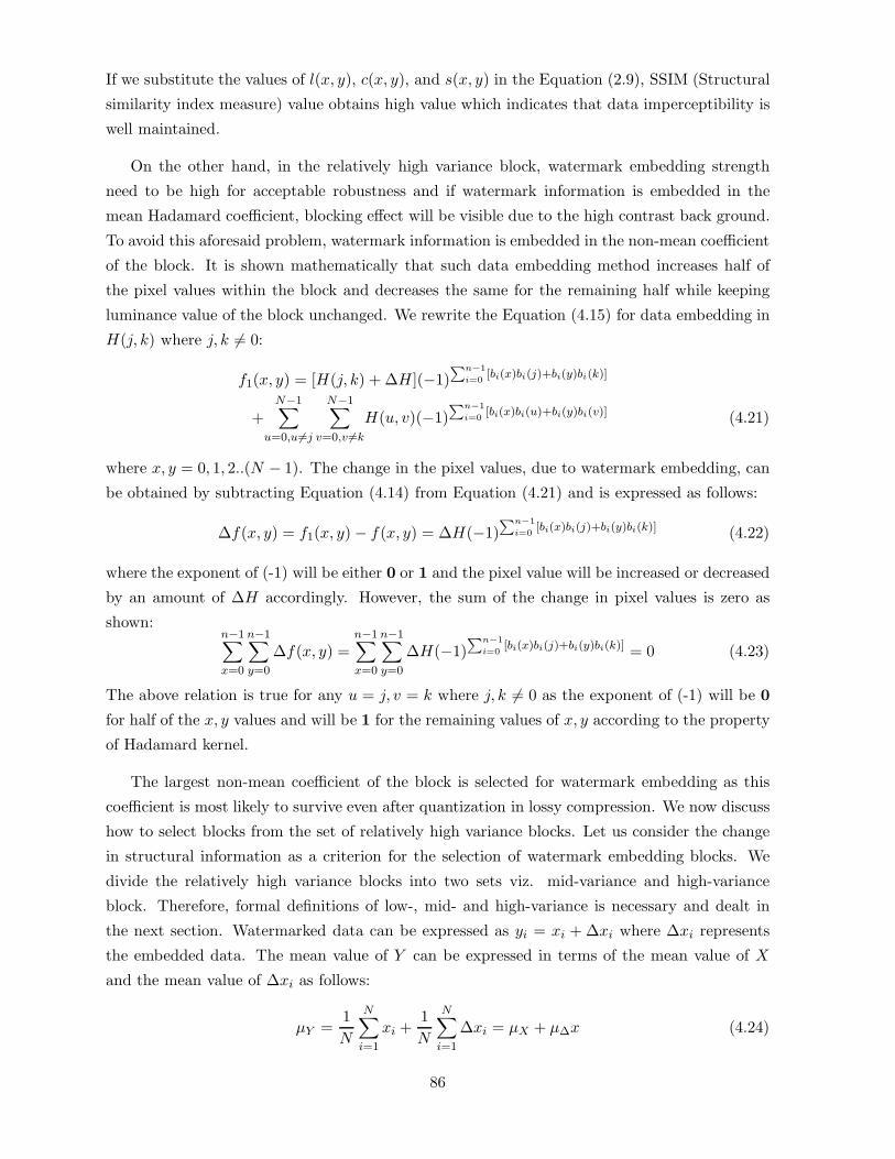
If we substitute the values of l(x, y), c(x, y), and s(x, y) in the Equation (2.9), SSIM (Structural
similarity index measure) value obtains high value which indicates that data imperceptibility is
well maintained.
On the other hand, in the relatively high variance block, watermark embedding strength
need to be high for acceptable robustness and if watermark information is embedded in the
mean Hadamard coefficient, blocking effect will be visible due to the high contrast back ground.
To avoid this aforesaid problem, watermark information is embedded in the non-mean coefficient
of the block. It is shown mathematically that such data embedding method increases half of
the pixel values within the block and decreases the same for the remaining half while keeping
luminance value of the block unchanged. We rewrite the Equation (4.15) for data embedding in
H(j, k) where j, k �= 0:
f1(x, y) = [H(j, k) + ∆H](−1)∑n−1
i=0[bi(x)bi(j)+bi(y)bi(k)]
+N−1∑
u=0,u �=j
N−1∑v=0,v �=k
H(u, v)(−1)∑n−1
i=0[bi(x)bi(u)+bi(y)bi(v)] (4.21)
where x, y = 0, 1, 2..(N − 1). The change in the pixel values, due to watermark embedding, can
be obtained by subtracting Equation (4.14) from Equation (4.21) and is expressed as follows:
∆f(x, y) = f1(x, y) − f(x, y) = ∆H(−1)∑n−1
i=0[bi(x)bi(j)+bi(y)bi(k)] (4.22)
where the exponent of (-1) will be either 0 or 1 and the pixel value will be increased or decreased
by an amount of ∆H accordingly. However, the sum of the change in pixel values is zero as
shown:n−1∑x=0
n−1∑y=0
∆f(x, y) =n−1∑x=0
n−1∑y=0
∆H(−1)∑n−1
i=0[bi(x)bi(j)+bi(y)bi(k)] = 0 (4.23)
The above relation is true for any u = j, v = k where j, k �= 0 as the exponent of (-1) will be 0
for half of the x, y values and will be 1 for the remaining values of x, y according to the property
of Hadamard kernel.
The largest non-mean coefficient of the block is selected for watermark embedding as this
coefficient is most likely to survive even after quantization in lossy compression. We now discuss
how to select blocks from the set of relatively high variance blocks. Let us consider the change
in structural information as a criterion for the selection of watermark embedding blocks. We
divide the relatively high variance blocks into two sets viz. mid-variance and high-variance
block. Therefore, formal definitions of low-, mid- and high-variance is necessary and dealt in
the next section. Watermarked data can be expressed as yi = xi + ∆xi where ∆xi represents
the embedded data. The mean value of Y can be expressed in terms of the mean value of X
and the mean value of ∆xi as follows:
µY =1N
N∑i=1
xi +1N
N∑i=1
∆xi = µX + µ∆x (4.24)
86

If we substitute µY in Equation (2.7), the structure comparison function after data embedding
in a block can be written as follows:
s(x, y) =1
N − 1
N∑i=1
(xi − µX)(xi + ∆xi − µX − µ∆x)
=1
N − 1
N∑i=1
(xi − µX)(xi − µX + ∆xi − µ∆x)
=1
N − 1
N∑i=1
(xi − µX)2 +1
N − 1
N∑i=1
(xi − µX)(∆xi − µ∆x) (4.25)
We may call (∆xi − µ∆x) as embedding variation. In most cases (∑N
i=1|(xi − µX)|) values are
greater for high-variance image block than the mid-variance one. Equation (4.25) shows that
(∆xi−µ∆x) value i.e. watermark embedding variation should be smaller for high variance image
block than the mid-variance one in order to preserve s(x, y) value same in both cases. In other
words, to lose the same structure information due to embedding, the watermark strength would
be higher in the case of the mid-variance blocks compared to the high variance blocks. High
resiliency can be achieved when watermark strength is high and this is the reason of selecting
mid- variance blocks for designing robust data embedding.
4.4.1.2 Watermark embedding process
Let us assume that the cover image I is a gray-level image of size (N × N), where N = 2p
and the digital watermark symbol (logo) W is a binary image of size (M ×M) where M = 2n.
The values of p and n indicate the size of the cover and the watermark image where p >> n,
typically (p/n) ≥ 4. The flowchart of watermark embedding is shown in Fig. 4.2.
Step 1: Selection of region for data embedding and formation of secret image S1
The entire cover image I is partitioned into (q × q) non-overlapping blocks where the value of q
is assumed to be 8 in the present case. However, q can accept any value 2k for any integer value
of k.
The variance for pixel values of each block is computed and the values are sorted in ascending
order. If the size of the watermark symbol is (N ×N), then two sets of N2 blocks corresponding
to the smallest and the largest N2 variances are termed as low- and high-variance blocks. The
remaining N2 blocks lying within the variance ranging from [(M2/(p2 ∗ 2)]-N2/2 to [(M2/(p2 ∗2)]+N2/2 in ascending order arrangement are called mid- variance blocks.
A three-level intermediate image map S1 of size (N/q×N/q) is constructed where each block
of the cover image is mapped as a point in the intermediate image. A 2-bit code is required to
represent the three levels, the low-, mid-variance, and the remaining blocks. The entire process
87

of region selection for watermark embedding is described using the modules A, B, C, D and E
in the flowchart shown in Fig. 4.2.
Step 2: Spatial dispersion of watermark image
The binary watermark image is spatially dispersed (L1) using a PN code generated by a linear
feedback shift register (LFSR). This is shown in modules G and H in the flowchart of the Fig.
4.2.
Step 3: Watermark embedding in low-variance blocks
Fast Hadamard transformation is applied on each low- and mid-variance block of the cover
image. Let Hu,v,b be the (u, v)-th coefficients of the block b, where H0,0,b is the mean coefficient
of the same. The integer part of the mean coefficient for each block is denoted by H0,0,b. A
suitable lower order bit of H0,0,b is replaced by one pixel from the spatially dispersed binary
watermark image L1. The fractional part of H0,0,b is now appended with the modified H0,0,b
value. This is shown in module F in the flowchart for watermark embedding.
Step 4: Watermark embedding in mid-variance blocks and formation of secret image S2
The same binary watermark pixels are also embedded in the mid-variance image blocks. For
each block, the highest non-mean Hadamard coefficient (ignoring its sign), (Hu,v,b)�= H0,0,b is
selected. The integer part of the selcted coefficient is denoted by Hu,v,b and a suitable lower
order bit of Hu,v,b is replaced by one pixel of the spatially dispersed binary watermark symbol
L1. The process is exactly same as described in Step 3. The fractional part of (Hu,v,b) is now
appended with the modified Hu,v,b value.
The secret image S2 of size (N×N) is formed, where each pixel value of the image represents
the positional information of the desired highest Hadamard coefficient within the mid-variance
block. Watermark embedding in the mid-variance blocks of the cover is shown in module J and
the formation of secret image S2 is shown in module M of Fig. 4.2.
Step 5: Formation of watermarked image
Block-based fast inverse Hadamard transformation is applied to the set of blocks with watermark
embedding in Steps 3 and 4. These sets of blocks and non-watermarked blocks of the cover
image are then placed in the proper positions of the cover image, and the watermarked image
is obtained. These modules are labelled as I, O, N and X in Fig. 4.2.
88

Figure 4.2: Flowchart for watermark embedding
Step 6: Robustness against compression using adaptive negative modulation
An adaptive modulation applied to mid-variance blocks enhances robustness for the embed-
ded watermark against lossy compression. This adaptive modulation modifies the value of the
watermarked coefficient in the direction opposite to that of the expected coefficient value ob-
tained after lossy compression. In other words, each Hadamard coefficient used for watermark
embedding (in each mid-variance block) is compared before and after lossy compression. If it
is found that the watermarked coefficient is decreased (increased) after lossy compression, the
value is increased (decreased) by modifying the lower order bit planes. The modification should
be done in such a way so as to preserve the hidden data. This type of modification for transform
coefficients is called negative modulation, which is described as follows.
For example, let us consider the binary watermark pixel is embedded in the third LSB of
Hadamard coefficient Hu,v,b i.e., in a2 in a sequence of an,...a1,a0 used to represent bitplanes. If
a2 assumes a value of 1 (the watermark pixel value), then a2a1a0 will be 110 corresponding to
the two LSBs of Hu,v,b as 10. This modified Hadamard coefficient is denoted by H1u,v,b which
after a lossy compression assumes H2u,v,b. Three changes are made to accommodate this lossy
compression as follows:
89
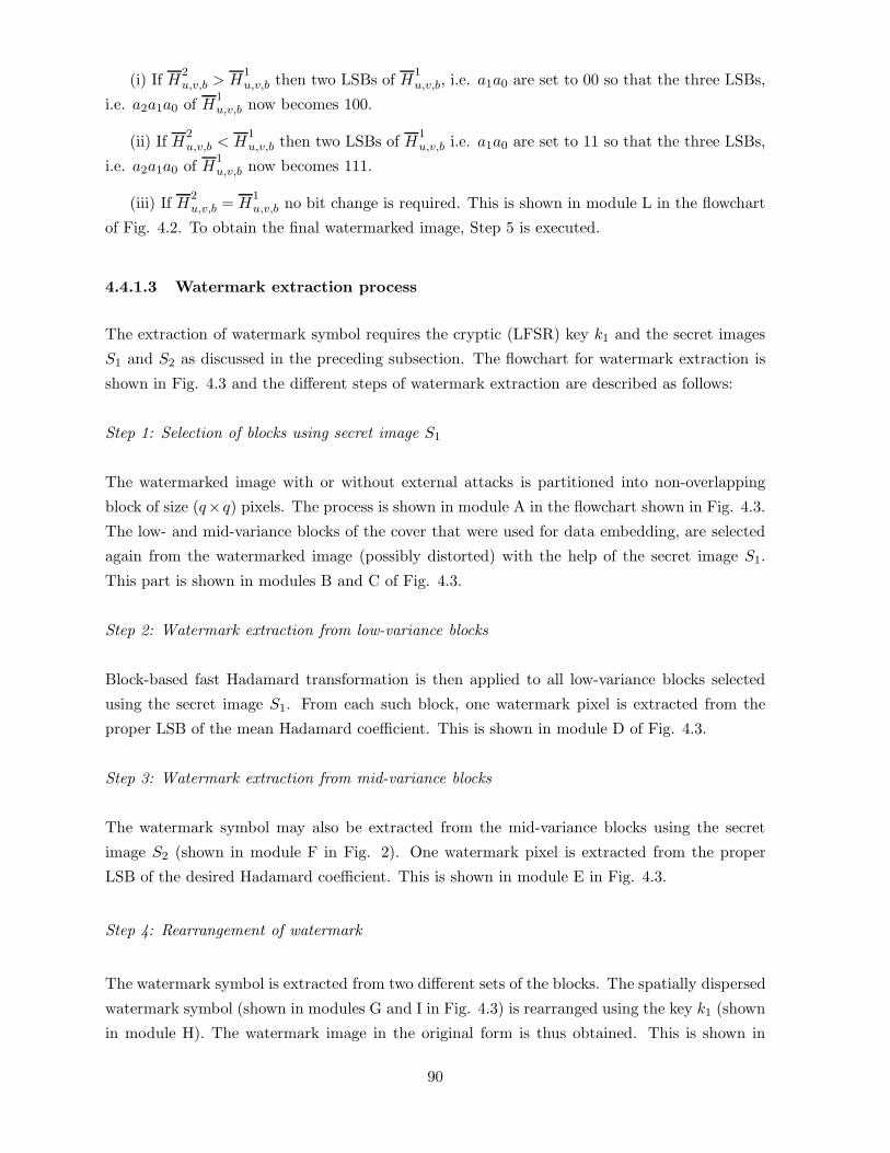
(i) If H2u,v,b > H
1u,v,b then two LSBs of H1
u,v,b, i.e. a1a0 are set to 00 so that the three LSBs,
i.e. a2a1a0 of H1u,v,b now becomes 100.
(ii) If H2u,v,b < H
1u,v,b then two LSBs of H1
u,v,b i.e. a1a0 are set to 11 so that the three LSBs,
i.e. a2a1a0 of H1u,v,b now becomes 111.
(iii) If H2u,v,b = H
1u,v,b no bit change is required. This is shown in module L in the flowchart
of Fig. 4.2. To obtain the final watermarked image, Step 5 is executed.
4.4.1.3 Watermark extraction process
The extraction of watermark symbol requires the cryptic (LFSR) key k1 and the secret images
S1 and S2 as discussed in the preceding subsection. The flowchart for watermark extraction is
shown in Fig. 4.3 and the different steps of watermark extraction are described as follows:
Step 1: Selection of blocks using secret image S1
The watermarked image with or without external attacks is partitioned into non-overlapping
block of size (q×q) pixels. The process is shown in module A in the flowchart shown in Fig. 4.3.
The low- and mid-variance blocks of the cover that were used for data embedding, are selected
again from the watermarked image (possibly distorted) with the help of the secret image S1.
This part is shown in modules B and C of Fig. 4.3.
Step 2: Watermark extraction from low-variance blocks
Block-based fast Hadamard transformation is then applied to all low-variance blocks selected
using the secret image S1. From each such block, one watermark pixel is extracted from the
proper LSB of the mean Hadamard coefficient. This is shown in module D of Fig. 4.3.
Step 3: Watermark extraction from mid-variance blocks
The watermark symbol may also be extracted from the mid-variance blocks using the secret
image S2 (shown in module F in Fig. 2). One watermark pixel is extracted from the proper
LSB of the desired Hadamard coefficient. This is shown in module E in Fig. 4.3.
Step 4: Rearrangement of watermark
The watermark symbol is extracted from two different sets of the blocks. The spatially dispersed
watermark symbol (shown in modules G and I in Fig. 4.3) is rearranged using the key k1 (shown
in module H). The watermark image in the original form is thus obtained. This is shown in
90

Figure 4.3: Flowchart for watermark extraction
modules J and K in Fig. 4.3. This completes the watermark extraction process. The watermark
symbol, extracted from the two different regions preserve different visual recognizability based
on the nature and depth of external attacks.
The additional information for detection of the present scheme is lower than that of [112]. The
current watermark extraction process uses only the watermark embedding positions but the
latter method requires the watermark embedding positions as well as the embedding strength
factor corresponding to each embedding position. Moreover, computation cost and complexity
of the proposed method is low compared to the previous one [112].
4.4.1.4 Performance evaluation
The proposed watermark embedding method is a block-based transform domain approach, where
a gray-level cover image of size (256 × 256) and a binary watermark image of size (16 × 16)
have been considered. The proposed algorithm is efficient with respect to its DCT domain
implementation for both embedding and extraction of watermark. The figures for computation
are approximately 5 seconds and 3 second for FHT and 12 seconds and 9 seconds for DCT
91

Figure 4.4: (a) Cover image F. Boat; (b)Watermark symbol;(c) Watermarked image; (d)Cover
image Bear
domain implementation.
Fig. 4.4 (a) (Fishing Boat) shows an original test image and Fig. 4.4 (c) shows the wa-
termarked image using logo/hidden symbol M of Fig. 4.4 (b). The PSNR and MSSIM values
between the watermarked image and the original image is 36.12 dB and 0.9766 respectively with
ε-value, i.e. security value of 0.006625. High MSSIM value indicates that quality degradation
of the watermarked image is hardly perceptible, and at the same time low ε-value indicates the
higher security of the hidden information against statistical analysis.
We compare the proposed method with [112]. Also [246] for colored image modified for
monochrome still image has been compared with this method. It is found that for almost same
order of embedding strength, present algorithm offers better imperceptibility and security in
either situation. The data imperceptibility measure and the security of the hidden information
for each of the methods referred above are shown in Table 4.1. Algorithm 1 corresponds to the
proposed method while Algorithm 2 & Algorithm 3 indicate the works reported in [112] & [246]
respectively. Robustness against common signal processing operations and deliberate image
degradations for the proposed method of watermarking have been reported in the subsequent
paragraphs.
(A) Robustness against common image degradations
The operations include normal signal processing methods applicable to any image during the
process of transmission and storage. Robustness against such different possible image processing
operations are shown in tables for other five benchmark images [1] such as Black Bear (Fig. 4.4
(d)), New York (Fig. 4.5 (a)), Opera (Fig. 4.5 (b)), Lena (Fig. 4.5 (c)), and Pills (Fig. 4.6 (a)).
92

Table 4.1: Imperceptibility and security value of the hidden data for algorithms 1, 2, 3
Test MSSIM Security MSSIM Security MSSIM Security
Image value ε-value value ε-value value ε-value
algo1 algo1 algo 2 algo 2 algo 3 algo 3
Fishing Boat 0.9466 0.0124 0.9042 0.1724 0.9241 0.1312
Bear 0.9587 0.0133 0.9164 0.1986 0.9224 0.1154
New York 0.9623 0.0168 0.9172 0.2125 0.9426 0.0992
Opera 0.9431 0.0154 0.9126 0.1856 0.9267 0.1054
Lena 0.9512 0.0168 0.9147 0.2067 0.9356 0.2002
Pill 0.9498 0.0172 0.9173 0.1925 0.9273 0.1675
Figure 4.5: Cover images (a) New York; (b)Opera;(c) Lena
(1) Mean and Gaussian filtering
Fig. 4.6 (b) shows the blurred version of the watermarked image Fishing Boat obtained af-
ter applying (3 × 3) mask twice. The PSNR value of the image corresponding to Fig. 4.6(b) is
25.5763 dB, whereas Fig. 4.6(c) shows the extracted watermark symbol with NCC= 0.86. It is
very difficult to correlate the recognizability of the watermark pattern with NCC and I(X;Y )
values; however, experimental results suggest that an NCC value of (∼ 0.6) and I(X;Y ) value
of (∼ 0.04) can be considered as threshold index for recognizability of the logo M. The water-
marked image (PSNR = 24.45 dB) after three times Gaussian filtering with variance 1 (window
size 9 × 9) is shown in Fig. 4.7(a). The extracted watermark image with NCC= 0.82 is shown
in Fig. 4.7(b). The results of mean and gaussian filtering are summarized in Table 4.2.
93

Figure 4.6: (a) Cover image Pills; (b) Blurred version of watermarked image Fishing Boat after
applying (3 × 3) mask twice ; (c) Extracted watermark from Fig. (b)
Table 4.2: Results of mean and gaussian filtering for the proposed variance based method
Test Watermarked Mean filtered Retrieved Gaussian filtered Retrieved
Image image (dB) image (dB) logo image (dB) logo
(twice) I(X;Y ) (four times) I(X;Y )
Fishing Boat 36.12 26.23 Yes (0.069) 24.45 Yes (0.064)
Bear 34.78 25.09 Yes (0.097) 25.29 Yes (0.0985)
New York 34.34 27.77 Yes (0.143) 24.21 Yes (0.156)
Opera 36.03 24.18 Yes (0.143) 25.18 Yes (0.198)
Lena 37.02 27.66 Yes (0.212) 26.63 Yes (0.203)
Pill 34.06 25.94 Yes (0.0978) 22.24 Yes (0.0956)
(2) Median and Image Sharpening filtering
Fig. 4.7(c) shows the watermarked image Fishing Boat after applying median filtering five times
using spatial mask of size 3× 3. The PSNR value of the image shown in Fig. 4.7(c) is 23.52 dB.
The extracted watermark symbol is shown in Fig. 4.7(d) having NCC value 0.91. Fig. 4.8(a)
shows the watermarked image Fishing Boat after image sharpening operation, with PSNR value
17.24 dB. The extracted watermark symbol is shown in Fig. 4.8(b) with NCC value 0.94. Results
of median filtering and image sharpening are shown in Table 4.3.
(3) Image cropping operation
Image cropping operation has been simulated by altering the pixel values of twenty rows and
columns from the broader of the image with some arbitrary value (say 150). It is logical to think
that the extracted watermark may not have good visual quality or recognizability if watermark
pixels are inserted in a sequential manner rather than in spatially dispersed form. Thus, spatial
dispersion of the watermark symbol, before its insertion, has a significant role in fighting against
various image cropping operations. Fig. 4.8(c) shows the watermarked image fishing boat
94

Figure 4.7: (a) Watermarked image after Gaussian filtering; (b) Extracted watermark; (c) Wa-
termarked image after five times median filtering using mask of size (3 × 3); (c) Extracted
watermark
Table 4.3: Results of median filtering and image sharpening
Test Stego Median filtered Retrieved Sharpened Retrieved
Image image (dB) image (dB) logoI(X;Y ) image (dB) logo I(X;Y )
(thrice) (five times)
Fishing Boat 36.12 23.52 Yes (0.132) 17.24 Yes (0.091)
Bear 34.78 26.35 Yes (0.156) 20.02 Yes (0.087)
New York 34.34 18.94 Yes (0.213) 18.34 Yes (0.205)
Opera 36.03 24.89 Yes (0.176) 19.04 Yes (0.103)
Lena 38.02 27.76 Yes (0.253) 17.66 Yes (0.091)
Pill 34.06 25.31 Yes (0.098) 19.33 Yes (0.065)
(PSNR = 21.65 dB) with such operation, and the extracted watermark symbol with NCC =
0.58 is shown in Fig. 4.8(d).
(4) Manipulation of LSB and JPEG compression
Elementary signal processing through manipulation in LSBs is likely to be applied in order to
remove the watermark. Evidence of such an operation is shown in Fig. 4.9(a) where three least
significant bits of all pixels in the watermarked image have been simultaneously complemented.
The PSNR value for such distorted watermarked image (Fig. 4.9(a)) is 35.49 dB. The extracted
watermark symbol is shown in Fig. 4.9(b) with an NCC value of 0.85. It is well known that
as compression ratio increases, the NCC value of the extracted symbol decreases and the visual
quality of the extracted watermark also degrades accordingly. Experimental results show that
watermark information hidden in the desired Hadamard coefficients of the mid-variance blocks
95

Figure 4.8: (a) Watermarked image after sharpening operation; (b) Extracted watermark ; (c)
Watermarked image after cropping operation; (d) Extracted watermark
has shown survivability more even after JPEG compression at low quality factor and low PSNR
values. Fig. 4.9(d) shows the extracted watermark symbols from Fishing Boat obtained after
JPEG compression with quality factor 30. The compressed image (PSNR = 16.26 dB) is shown
in Fig. 4.9(c). The NCC value of the extracted watermark symbol is 0.70. Adaptive modulation
helps in preserving watermark within the compressed watermarked image at the cost of marginal
visual degradation of the watermarked image.
Table 4.4: Results on robustness against deliberate LSB(s) manipulation and additive noise
Test Stego Distorted Retrieved Noisy Retrieved
Image image (dB) image (dB) logo( NCC) image logo
three bits I(X;Y ) in(dB) I(X;Y )
Fishing Boat 36.12 38.12 Yes (0.198) 31.35 Yes (0.175)
Bear 34.78 35.12 Yes (0.167) 30.03 Yes (0.154)
New York 34.34 34.78 Yes (0.187) 29.77 Yes (0.113)
Opera 36.03 34.23 Yes (0.176) 31.55 Yes (0.156)
Lena 37.02 36.56 Yes (0.093) 34.23 Yes (0.089)
Pill 34.06 22.67 Yes (0.098) 27.34 Yes (0.085)
(5) Random noise addition
It is customary to assume that watermarked images communicated through a channel is con-
taminated with additive random noise leading to deterioration in the quality of the extracted
watermark. The experiment for the purpose has been designed where values for 15% randomly
selected pixel are altered by 15% of their gray value. Results of this operation for the water-
marked image with PSNR value 31.35 dB is shown in Fig. 4.10(a). The extracted watermark as
shown in Fig. 4.10(b) bears NCC value 0.72. Results of LSB manipulation and noise addition
96
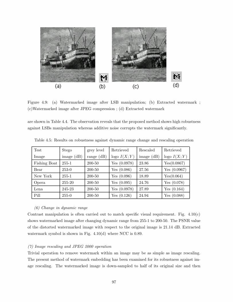
Figure 4.9: (a) Watermarked image after LSB manipulation; (b) Extracted watermark ;
(c)Watermarked image after JPEG compression ; (d) Extracted watermark
are shown in Table 4.4. The observation reveals that the proposed method shows high robustness
against LSBs manipulation whereas additive noise corrupts the watermark significantly.
Table 4.5: Results on robustness against dynamic range change and rescaling operation
Test Stego grey level Retrieved Rescaled Retrieved
Image image (dB) range (dB) logo I(X;Y ) image (dB) logo I(X;Y )
Fishing Boat 255-1 200-50 Yes (0.0978) 23.86 Yes(0.0867)
Bear 253-0 200-50 Yes (0.086) 27.56 Yes (0.0967)
New York 255-1 200-50 Yes (0.096) 18.89 Yes(0.064)
Opera 255-20 200-50 Yes (0.095) 24.76 Yes (0.078)
Lena 245-23 200-50 Yes (0.0978) 27.89 Yes (0.164)
Pill 255-0 200-50 Yes (0.126) 24.94 Yes (0.088)
(6) Change in dynamic range
Contrast manipulation is often carried out to match specific visual requirement. Fig. 4.10(c)
shows watermarked image after changing dynamic range from 255-1 to 200-50. The PSNR value
of the distorted watermarked image with respect to the original image is 21.14 dB. Extracted
watermark symbol is shown in Fig. 4.10(d) where NCC is 0.89.
(7) Image rescaling and JPEG 2000 operation
Trivial operation to remove watermark within an image may be as simple as image rescaling.
The present method of watermark embedding has been examined for its robustness against im-
age rescaling. The watermarked image is down-sampled to half of its original size and then
97
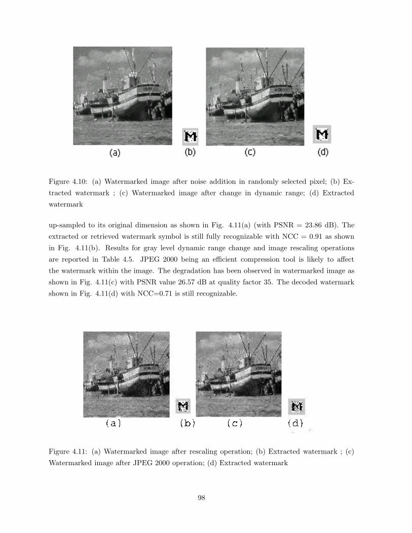
Figure 4.10: (a) Watermarked image after noise addition in randomly selected pixel; (b) Ex-
tracted watermark ; (c) Watermarked image after change in dynamic range; (d) Extracted
watermark
up-sampled to its original dimension as shown in Fig. 4.11(a) (with PSNR = 23.86 dB). The
extracted or retrieved watermark symbol is still fully recognizable with NCC = 0.91 as shown
in Fig. 4.11(b). Results for gray level dynamic range change and image rescaling operations
are reported in Table 4.5. JPEG 2000 being an efficient compression tool is likely to affect
the watermark within the image. The degradation has been observed in watermarked image as
shown in Fig. 4.11(c) with PSNR value 26.57 dB at quality factor 35. The decoded watermark
shown in Fig. 4.11(d) with NCC=0.71 is still recognizable.
Figure 4.11: (a) Watermarked image after rescaling operation; (b) Extracted watermark ; (c)
Watermarked image after JPEG 2000 operation; (d) Extracted watermark
98

Figure 4.12: (a) Watermarked image after collusion using proposed algorithm, (b)-(f) Watermark
images, (b’)-(f’) Extracted watermark images; (u) Watermarked image after collusion operation
using proposed algorithm and the other two algorithms,(v)-(x) Watermark images, (v’)-(x’)
Extracted watermark images
(B) Robustness against deliberate image degradations
The operations include some intentional signal processing methods that are applied in order to
render the already embedded watermark or to cast a new watermark to an already marked im-
age, to change the ownership. Robustness performance of the proposed watermark embedding
for few such operations are described as follows.
(1) Collusion attack
Several watermarks could be embedded into a single cover image with an objective of making
the original unreadable. We embed separately five binary watermark images (shown in Figs.
4.12 (b)-(f)) into Fishing Boat image using the proposed method and are then averaged. Fig.
4.12(a) shows the watermarked image after such type of collusion attack along with the extracted
watermark images shown in Fig. 4.12 (b′ − f
′). We also test resiliency against the attack where
three watermark images (shown in Fig. 4.12 (v)-(x)) are embedded into the same host image
separately using the methods [112, 246, 49] and are averaged. The watermarked image after
such type of collusion attack is shown in Fig. 4.12 (u) and the extracted watermark images from
it are shown in Fig. 4.12 (v′ −x′
). Good recognizability of all the extracted watermark images in
Fig. 4.12 (b′ − f
′) and the watermark (logo) M in Fig. 4.12 v
′highlight the superior robustness
of our method compared to [112, 246]. The good visual recognizability of the extracted ’checker
board’ logo (Fig. 4.12 x′) is due to low data rate embedding and improved robustness property
of SS (Algorithm 3) watermarking scheme. Collusion attack being an averaging operation of
several watermarked images for the same cover, the edge information is affected more in the
resultant watermarked image. In [112], watermark information is embedded using edge and
texture information of the cover and that is why the visual quality of the extracted watermark
99

as shown in Fig. 4.12 (w′) is very poor.
(2) Deliberate embedding
The resiliency of the proposed algorithm against over watermarking i.e. deliberate embedding is
tested. We embed three different watermark images successively into a sigle cover image Fishing
Boat using algorithms 1, 2 and 3. The watermarked images are shown in Figs. 4.13 (a), (b),
and (c) with MSSIM values 0.9766, 0.8923, and 0.8524 respectively. The extracted watermark
image (using the proposed algorithm) from the resultant watermarked image is quite visually
recognizable i.e. the proposed algorithm is resilient against deliberate removal attack.
(3) Image scaling
Robustness of the proposed algorithm is tested by changing the aspect ratio of the watermarked
image in three different forms as shown in Fig. 4.14. The X and Y values mentioned in the
figures denote the scale factor for the horizontal and vertical size of the watermarked image.
Figs. 4.14(b), 4.14(d), and 4.14(f) show the watermark images extracted from Figs. 4.14(a),
4.14(c), and 4.14(e) respectively. NCC values for the extracted watermark symbols are 1, 1, and
0.65 with mutual information values of 0.287313, 0.287313 and 0.095641 respectively.
Figure 4.13: (a) Watermarked image after deliberate embedding of three watermarks; (b) Ex-
tracted watermark
(4) Image rotation
Resiliency of the proposed algorithm is tested against small geometric attack in the form of
image rotation. Synchronization poses a major practical problem in image rotation where the
100

angle of rotation undergone by the watermarked image needs to be estimated. In Algorithm
[112], the authors claim that their technique is resilient against small rotation ranging within
30 degrees without touching synchronization problem. The proposed algorithm accommodates
method to estimate the angle of rotation. The variances of the blocks of the watermarked image
at the position (16, 0)-th and (16, 16)-th are preserved in the intermediate image map S1. The
watermarked image after any arbitrary clockwise or anti-clockwise rotation, has to be processed
by comparing the variances in the present orientation with stored ones, and are adjusted with
requisite angle of rotation for matching.
Figure 4.14: (a), (c), (e) Watermarked images after change in aspect ratio (a)( X=1.2 and
Y=0.8) ;(c)(X=0.8 and 1.0 and Y=1.2); (e)(X=1.2 and Y=1.0) respectively); (b), (d), (f)
Extracted watermark from Fig. (a), (b) and (c)images respectively
It has been observed from the results of the large number of watermarked images where the
extracted watermark preserves its visual recognizability, so long the difference in variance lies
within 10%. Figs. 4.15(a) and 4.15(b) show the watermarked images obtained after small ro-
tation by angles of 10 and 15 degrees respectively. The corresponding watermarks having NCC
values of 0.87 and 0.62 are shown in Figs. 4.15(c) and 4.15(d) respectively.
(5) Image cropping
Watermarked image distorted by image cropping operation preserves the watermark depending
upon the degree of cropping. Present study reveals that for images with 25% and 50% cropping
maintains reasonable values for NCC as 0.76 and 0.64 respectively. Figs. 4.15(u)-(v) show the
resiliency result of the proposed algorithm against image cropping operation. Figs. 4.15(u) and
4.15(X) show the respective watermarked images and the extracted watermark images are shown
in Fig. 4.15(w) and Fig. 4.15(x) respectively.
101

Figure 4.15: (a), (b) Watermarked images after small rotation; (c), (d) Extracted watermark im-
ages respectively;(u), (v) Watermarked images after 25% and 50% cropping; (w), (x) Extracted
watermark images respectively
To test the robustness of the proposed scheme, software package of checkmark [227] with all
default parameters are used. Results are enlisted in Table 4.6. Experiment results support that
Table 4.6: Test results of checkmark packageName of NCC recogni- Name of NCC recogni-
attack value zability attack value zability
Wiener filtering 0.71145 yes dither 0.425 no
dpr 0.692 yes trimeadmin 0.646 yes
dprcorr 0.482 no copy-collage 0.446 no
midpoint 0.743 yes projective 0.734 yes
threshold 0.686 yes ratio 0.743 yes
hard threshold 0.712 yes rowcol 0.732 yes
soft threshold 0.692 yes shearing 0.472 no
sampledownup 0.764 yes warping 0.672 yes
stirMark 0.421 no nulineremove 0.723 yes
the selection of Hadamrd transform as signal decomposition tool shows better performance at
low quality compression compared to DCT, when both type of compression operations are taken
into consideration. This is shown graphically in Fig. 4.16 and its improvement with adaptive
modulation. Further the high mutual information values for the extracted watermark images
for low quality compression supports better robustness performance for DHT over DCT.
102

Figure 4.16: Robustness performance of the algorithm against lossy compression operation;
Legend DCT-NG, DHT-NG correspond to the result of data embedding in DCT and DHT
coefficients after negative modulation
4.4.2 Method 2: Selection of embedding regions based on image information[150,
164]
4.4.2.1 Image information for data hiding
When an image is perceived by human visual system, visual information is extracted not from
the single pixel alone but from a group of pixels in its neighborhood. Moreover, in most of the
natural images, a strong two dimensional (2D) spatial correlation exists among the neighboring
pixels, that results in structural information of the image. If there is a noticeable change in
spatial correlation of the neighboring pixels during data manipulation, image visual quality is
likely to be degraded. One of the good measure of this spatial correlation of neighboring pixels
is the average information (entropy) as shown in Equation (4.26) due to Shannon, which is a
global measure with respect to the image/sub image. According to Shannon’s definition, the
entropy of an n-elements set is
H = −n∑
i=1
pi logpi (4.26)
where pi is the probability of occurrence of the event ”i” with 0 ≤ pi ≤ 1 and∑n
i=1pi=1 [247].
The value depends solely on the probability distribution of the pixel intensities but does not
consider the co-occurrence of the pixel values. That is why this measure does not always capture
the actual pictorial information of the image/sub image. This is shown in Fig. 4.17 where the
entropy value is same for all the three binary images although the pictorial information content
(measure of uncertainty) is decreasing in order from Fig. 4.17a, Fig. 4.17b to Fig. 4.17c. So
for a real image, a sub image with a particular entropy value may represent a smooth as well
as noisy or edgy region. This indicates that along with average information value, the average
103

Figure 4.17: Three different binary images with same entropy value
edge information of the image block is also important for selection of embedding regions in
order to design robust and imperceptible watermarking scheme. It is well known that edge is an
important image information characteristic which carries major information about any natural
image. So it is desirable that, during modification of the cover image for watermark embedding,
the minimum number of edge points should be modified. Moreover, the edges (the high spatial
frequency points) are getting modified to a greater extent during lossy compression which means
that the edge points are relatively unstable site for watermark embedding.
The very basic assumption of Shannon’s entropy measure is to consider the signal as a long
sequence of symbols and the entropy of that sequence solely depends on the relative occurrence
of the symbols irrespective of their position of occurrence. It has been shown in [202] that an
exponential form of entropy function can capture two dimensional spatial correlation of images
in a better way compared to conventional Shannon’s entropy. The modified form of entropy for
an image block is defined in [202] as
H =n∑
i=1
pi expui =
n∑i=1
pi exp1−pi (4.27)
where ui=(1 − pi) is the ignorance or uncertainty of the pixel value.
To calculate the average edge information i.e. edge entropy of the block, first the edge map
is calculated using the conventional gradient operator. The edginess or the strength of edge of
a pixel automatically considers the effect of neighborhood pixel values, so the measure of edge
entropy of sub image is dependent on the relative occurrence of these edge strength irrespective
of their position. This says that Shannon’s form of entropy can be applied to calculate the
average edge information of each block using the edge map.
4.4.2.2 Blocks and coefficients selection for embedding
The cover image is partitioned into (p × p) non overlapping block where p = 2n, and n =
1, 2, 3..etc. If the size of the cover image is (N × N), the total N2/p2 number blocks are
obtained from the cover image, and in general p << N . The value of p depends on the size
of the watermark. The edge entropy or average edge information of each block is calculated
from edge map using Equation (4.26). The average gray information (visual) is calculated using
104

Equation (4.27). The average information due to gray level and edge entropy value of each block
are added, the total values obtained are sorted in ascending order of magnitude and stored as
linear chain. Fig. 4.18 shows the relative position of the different informative blocks. Let
Figure 4.18: Linear chain showing the relative position of different information blocks
the size of the watermark symbol is (M ×M), then two sets of M2 blocks located at the top
(shown on the left) and the bottom end (shown on the right) are termed here as the low and the
high informative blocks respectively. The other M2 blocks corresponding to the entropy values
positioned between [(N2/(p2 ∗ 2)]-M2/2 to [(N2/(p2 ∗ 2)]+M2/2 in the chain is termed here as
the medium informative blocks.
If watermark information is embedded in the different transform coefficients of the high infor-
mative blocks, perceptual distortion will be less but at the same time the embedded information
is fragile against lossy compression and other signal processing operations. On the other hand,
watermark information embedded in the low informative blocks may be perceived but offers high
robustness against smoothing filtering. In order to make the scheme resilient against various
possible signal processing operations, watermark information is embedded redundantly both in
the low and the medium informative blocks. However, appropriate transform coefficients for
different blocks should be selected so that imperceptibility and robustness requirement can be
satisfied properly.
It is to be noted that in bit-replacement method for watermark embedding the pixel values
remain unchanged, or increased or decreased based on the match/mismatch characteristics be-
tween the watermark bits and the bit plane of the cover. We assume bit replacement method
of watermark embedding as a special case of additive embedding. Let us examine the effect of
additive watermarking to the change in average gray level information and the average edge in-
formation of the image block when watermark information is embedded both in the zeroth order
(H0,0) Hadamard coefficient and the other higher order (Hu,v) coefficient respectively. Let the
watermark information be embedded in the zeroth order coefficent H0,0 and embedding strength
is denoted by ∆w. Acoording to the Equations. (4.14) and (4.15) the change in pixel values
∆f(x, y), due to watermark embedding, can be written as follows:
∆f(x, y) = (∆w)(−1)∑n−1
i=0[bi(x)bi(0)+bi(y)bi(0)] = ∆w (4.28)
105

In Equation (4.28), ∆w is independent of x and y as the exponent of (−1) is 0 for bi(0) = 0.
This means that if ∆x amount of watermark information is added in the zeroth order Hadamard
coefficient of an image block, all the pixels values within the block in the watermarked image
are increased by ∆x. So both the average information and the average edge information remain
unchanged before and after watermark embedding.
On the other hand, to achieve the same degree of watermark decoding reliability after a given
degree of signal degradation in the watermarked images, embedding strength in the medium
informative blocks should be higher compared to that in the low informative blocks. The analysis
is based on the fact that there lies more uncertainty among the pixel value distribution in the
former type blocks compared to the latter type. So a given degree of signal degradation will
introduce more uncertainty in the medium informative blocks compared to the low informative
blocks. The effect of additive watermarking in any higher order Hadamard coefficient of a block
causes an increases in half of the pixel values while remaining pixel values are decreased. The
amount of change is the same in both the cases. We now have a relation according to Equations
(4.14), (4.21) and (4.22) to denote the change in the pixel values for data embedding in Hj,k
where j, k �= 0 as follows:
∆f(x, y) = ∆w(−1)∑n−1
i=0[bi(x)bi(j)+bi(y)bi(k)] = ±∆w (4.29)
If watermark information is embedded in the coefficient u = l, v = k where l, k �= 0 for other
transformation, say DCT, the change in pixel values can be written similar to the Equation
(4.29) as follows:
∆f(x, y) = f1(x, y) − f(x, y)
= ∆w cos[(2x + 1)lπ
2N] cos[
(2y + 1)kπ2N
] (4.30)
Equation (4.30) shows that the amount of changes are different for different pixels and the
value also depend on the choice of the particular coefficient to be used for embedding i.e. u and
v values. The result is also true for other popular transformations such as DFT, Fourier-Mellin,
and wavelet etc. So the results in Equations (4.29) and (4.30) can be summarized as follows:
(1) Image information is changed by less amount in case of Hadamard domain embedding com-
pared to other popular transform domain embedding as in the latter cases different pixel values
are changed by different amount due to the multivalued kernels.
4.4.2.3 Proposed watermarking technique
The cover image is a gray-scale image of size (N ×N) and watermark is a binary image of size
(M×M). The watermark insertion and extraction processes are exactly similar to that of earlier
algorithm.
106

4.4.2.4 Performance evaluation
The watermark is a binary image of size (16 × 16) and the cover image is a gray-scale image of
size (256×256), 8 bits/pixel. The proposed algorithm is efficient with respect to its DCT domain
implementation for both embedding and extraction of watermark. The figures for computation
are approximately 6 seconds and 4 second for FHT and 11 seconds and 9 seconds for DCT domain
implementation. Fig. 4.19(a) (Fishing Boat) shows an original test image and Fig. 4.19(c) and
Figure 4.19: (a) Cover image, (b) Watermark image, (c) Watermarked image using Hadamard
transform, (d) Watermarked image using DCT transform
Table 4.7: Imperceptibility and security value of the hidden data for the proposed entropy based
method, Ho and Shan method
Test MSSIM Security MSSIM Security MSSIM Security
Image value ε-value value ε-value value ε-value
Prop. algo Prop. algo Cox algo Cox algo Podl. algo Podl. algo
Fishing Boat 0.9614 0.0064 0.9042 0.1724 0.9241 0.1312
Bear 0.9756 0.0074 0.9164 0.1986 0.9224 0.1154
New York 0.9843 0.0077 0.9172 0.2125 0.9426 0.0992
Opera 0.9631 0.0084 0.9126 0.1856 0.9267 0.1054
Lena 0.9612 0.0075 0.9147 0.2067 0.9356 0.2002
Pill 0.9698 0.0083 0.9173 0.1925 0.9273 0.1675
4.19(d) show the watermarked images for DHT and DCT domain embedding respectively using
logo/hidden symbol M of Fig. 4.19(b). The average values of PSNR and MSSIM between the
watermarked images and the original images are 36.12 dB & 0.9766 for DHT domain embedding
and 33.24 dB & 0.9431 for DCT domain embedding. The ε-values, i.e. security values for the two
domain embedding are 0.006625 and 0.012451 respectively. Fig. 4.20 (a) shows graphically the
change in edge entropy values of the medium informative blocks both in DCT and DHT domain
embedding while Fig. 4.20(b) shows embedding distortion of the blocks as measure of Structural
SIMilarity index (SSIM) [288]. The horizontal axis of Figs. 4.20(a) and 4.20(b) represent those
256 blocks appeared as medium informative blocks in the ascending order arrangement. The
results obtained support the fact that change in image information due to watermark embedding
107

is lower in case of DHT compared to DCT. Experimental results show that data embedding in
the mid-informative blocks offer resiliency against dynamic range change of the gray values,
noise addition, image sharpening, lossy compression operations while data embedding in the
low-informative blocks are resilient against various types of smoothing filtering operations.
We compare the results of our algorithm with [224](Podilchuck algorithm of DCT domain
implementation) and [83] (Cox algorithm) and it is found that for almost same order of robust-
ness efficiency against lossy compression operations our algorithm offers best imperceptibility
(high PSNR and MSSIM values) and security (ε-value) values compared to the latter two algo-
rithms. The results of the imperceptibility and security comparison are shown in Table 4.7. The
detection overhead of the present scheme is lower compared to that of [224] since our watermark
extraction process needs only the watermark embedding positions but the latter method requires
the watermark embedding positions as well as the embedding strength factor corresponding to
each embedding position.
Figure 4.20: (a)Change in edge entropy of the medium informative blocks due to embedding,
(b) Change in structural information; Legend DCT, DHT correspond to the embedding using
DHT and DCT
Robustness of the proposed algorithm against different attacks available in the checkmark pack-
age [227] are shown in Table 4.8. Figs. 4.21(a) and (b) show graphically the robustness perfor-
mance of the proposed algorithm against JPEG and JPEG 2000 compression operations using
Fast Hadamard, and DCT transform. In the low- informative block, due to embedding, all
the pixel values are changed by same amount and in the same direction. Embedded water-
mark information are lost more after quantization operation of lossy compression. The loss of
embedded watermark information is comparatively less in case of data embedding in the mid-
informative block as watermark information are embedded in the highest coefficient other than
108

Table 4.8: Test results of checkmark package for the proposed entropy based method
Name of NCC recogni- Name of NCC recogni-
attack value zability attack value zability
Wiener filtering 0.68145 yes dither 0.465 no
dpr 0.712 yes trimeadmin 0.646 yes
dprcorr 0.458 no copy-collage 0.423 no
midpoint 0.723 yes projective 0.713 yes
threshold 0.642 yes ratio 0.762 yes
hard threshold 0.697 yes rowcol 0.756 yes
soft threshold 0.672 yes shearing 0.435 no
sampledownup 0.816 yes warping 0.645 yes
stirMark 0.346 no nulineremove 0.690 yes
the mean coefficient. Experiment results support that the selection of Hadamrd transform as
signal decomposition tool shows better performance at low quality compression compared to
DCT, when both type of compression operations are taken into consideration. The graphical
results also show that robustness performance is further improved using adaptive negative mod-
ulation during data embedding in the mid-informative blocks. Similar results are also found
when Hadamard domain implementation is compared with wavelet domain implementation of
the algorithm.
Figure 4.21: Robustness performance of the algorithm against lossy compression operations
(a) JPEG and (b) JPEG 2000; Legend DCT-NG, DHT-NG correspond to the result of data
embedding in DCT and DHT coefficients after negative modulation
Lastly we compare the performance of both LBM watermarking methods in terms of visual and
statistical invisibility of the hidden data as well as robustness performance against various signal
processing operations. It is to be noted that the amount of side information required for water-
109
mark extraction is exactly same for the methods. Experiment results show that their robustness
performance are almost similar although visual and statistical invisibility of the hidden data in
case of Method 2 is much superior to that of Method 1. This is possibly due to the use of image
information as well as average edge information for the selection of watermark embedding blocks.
Although robustness performance of both LBM methods are better compared to spatial domain
LBM and additive watermarking methods (as discussed in chapter 3), but these results are not
satisfactory in terms of varieties of attacks and the degree of robustness shown by the numerical
values found in Checkmark package. In fact robustness against various possible common signal
processing operations are achieved by embedding same watermark information redundantly in
two sets of blocks, and thus watermark embedding capacity is affected. We test robustness
performance by effectively embedding 256 bits of watermark information in an image of size
(256× 256). In the next section, we consider additive watermarking to have an improvement in
robustness-capacity.
4.5 Additive and Multiplicative Watermarking using Spread Trans-
form Technique
We use here spread transform (ST) technique using the transform coefficients of both the cover
and the watermark signal. Data embedding strength is nonadaptively/adaptively controlled sim-
ply by assigning weight factors expressed as fraction of the watermark and/or cover coefficients.
Refinement of weight factors based on HVS models [290, 291] is carried out while maintaining
the perceptual transparency of the cover data. The basic idea behind robustness improvement
of ST watermarking is that any component of the channel noise v that is orthogonal to the
spreading vector t does not impair watermark detection. Thus, an attacker, not knowing the
exact spreading direction t, has to introduce much larger distortion to impair a ST watermark
than a watermark embedded directly into original signal X. Implementation methods of ST
using nonadaptive and adaptive technique using the Characteristics of HVS are described in the
following subsections.
Spread transform (ST) watermarking, proposed by Chen and Wornell [67, 68, 69], is an
approach to spread watermark information over many host signal elements. Watermark infor-
mation is not directly embedded into the original signal X, but into the projection XST of X
onto a random sequence t. The term ”transform”, as used by Chen and Wornell, is somewhat
misleading as it implies pseudo-random selection of signal component XST to be watermarked
[69]. We develop spread-transform scheme by projecting τ data elements of the cover (X). The
message signal (m) is also transformed to τ transform elements. Data embedding is accom-
plished using the transform coefficients. τ may be called as spreading factor and the value of τ
may be different for the cover and the watermark. The spreading effect is further improved by
110

spatial dispersion of the message vector before taking projection. Moreover, in the most cases,
the size of the cover signals are larger than the messages permitting cover elements XST to be
chosen with greater flexibility.
Figure 4.22: Spread Transform watermarking using non-adaptive technique
4.5.1 Non-adaptive spread transform watermarking
Watermark embedding process is identical to that of additive embedding process. We use gray
scale image for both the cover and the watermark image. Data imperceptibility may be difficult
to achieve for grayscale watermark image but its use not only conveys unique information about
the owner, user or content but also preserves contextual information to a good extent after vari-
ous form of signal degradation. The block (8×8) based DCT or FHT (Fast Hadamard transform)
is applied over both the cover and the watermark image. In order to increase imperceptibility,
the transform coefficients of the cover and the watermark image are sorted in ascending order so
that the relatively large coefficient of the message signal will modulate the corresponding large
111

coefficient of the cover data. Moreover, robustness performance particularly after compression
operation is increased because watermark information is embedded into the large coefficients of
the cover signal and these coefficients are most likely to survive after such operation. Fig. 4.22
shows the block diagram representation of watermark insertion and extraction technique. The
watermark is embedded according to the Equation (1.4) and is written here for convenience of
analysis.
Xei = Xi + α.Wi (4.31)
where Xi and Xei are the i-th coefficients of the image before and after watermark embedding,
Wi is the i-th watermark coefficient and α is the embedding strength. We embed scaled version
of the watermark coefficients to the cover signal’s respective coefficients and do not modulate
watermark coefficients according to the cover coefficients. That is why this technique is non-
adaptive watermarking. After watermark embedding with the new modulation function, block
based inverse transform is applied and the watermarked image is formed.
The extraction of watermark information is given by the following relation:
W′i =
1α
(X′i −Xi) (4.32)
where X′i is the coefficients of the possibly distorted watermarked image, Xi is the coefficient
of the cover image and W′i is the estimated coefficient of the extracted watermark image. The
transform coefficients of the extracted watermark are placed in the respective position and block
based inverse transformation is applied to obtain the watermark image.
(1) Performance evaluation
We choose the watermark signal as 4 bits/pixel gray-scale image of size (64× 64) and the cover
image a gray-scale image of size (256 × 256), 8 bits/pixel. Fast Hadamard transform based
embedding method takes less time for watermark embedding and decoding compared to DCT
domain implementation of the algorithm. Visual quality of the watermarked image depends
on the embedding strength and is degraded with the increase of α-values i.e. the embedding
strength. Table 4.9 shows the visual quality (PSNR values) of the watermarked image, security of
the hidden data (using Kulback-Leibler distance) and quality of the extracted watermark images
(denoted by mutual information values) for different α-values and tested over large number of
images. Similar results are also found for other test images.
We test robustness performance of the method against various signal distortions and results
are shown in the Table 4.10. Even though watermark images are recognizable for these signal
processing operations but their performance are degraded with the little more increase in the
degree of distortions. Moreover, watermark embedding strength should be high resulting poor
visual quality of the watermarked image. Data imperceptibility and robustness can be well
maintained in adaptive watermarking and is discussed below.
112

Table 4.9: Imperceptibility, security and quality of the extracted watermark for different values
of the embedding strength for Non-adaptive ST method
α- PSNR Security I(X;Y ) Recogni-
values values values values zability
0.1 34.83 0.07014 0.01407 Bad
0.2 33.97 0.07862 0.03371 Bad
0.3 32.45 0.08119 0.04407 Bad
0.4 31.36 0.08425 0.07225 Fair
0.5 30.56 0.08734 0.07963 Fair
0.8 28.43 0.09226 0.09435 Good
1.0 27.34 0.10014 0.11024 Godd
2.0 26.25 0.13541 0.13818 Very Good
4.0 24.65 0.15659 0.17555 Very Good
4.5.2 Adaptive Spread transform techniques using the Characteristics of
HVS [156, 149]
Watermark embedding process is identical to that of multiplicative embedding as represented by
Equation (1.6). We now incorporate the characteristics of the human visual system (HVS) and
statistical information measure in spread transform watermarking. Data embedding strength
is adaptively controlled using the HVS models and perceptual transparency is maintained by
minimum alteration of the structural information of the cover data.
(a) Generation of modulation function
In section 2.4.1 of chapter 2, visual quality measure of the watermarked image suggests that
modulation function for data embedding should incorporate the effect of luminance, contrast
and structure information of the cover image so that data imperceptibility is ensured by mini-
mum alteration of structural features of the watermarked image. We further include the effect
of frequency sensitivity in modulation function to incorporate viewing condition although this
property of the HVS no way depends on the image content. Modulation function is gener-
ated from the transform domain analysis of HVS characteristics. It is assumed that watermark
information must be embedded after signal decomposition to design compression resilient em-
bedding scheme. Modulation function is derived based on Watson visual [290] and entropy
masking model [291]. Watson relates frequency sensitivity (Fu,v,b), luminance masking (Lu,v,b)
and contrast masking (Cu,v,b) for each DCT coefficients according to the following relations :
Lu,v,b = Fu,v,b(X0,0,b
X0,0)α (4.33)
113

Table 4.10: Robustness performance against various signal distortions for watermarked image
Fishing Boat
Name of PSNR I(X;Y)-value Recognizable
attack value of watermark or not
Mean filtering 24.64 0.0943 yes
Median filtering 26.56 0.1134 yes
Gaussian filtering 26.23 0.1024 yes
Dy. range change 22.32 0.0892 yes
Image sharpening 19.56 0.0934 yes
Histogram Equ. 21.34 0.1234 yes
Noise addition 30.34 0.1563 yes
Rescaling 25.64 0.1374 yes
Cu,v,b = max[Lu,v,b, |Xu,v,b|βu,v(Lu,v,b)1−βu,v ] (4.34)
where X0,0,b is the DC coefficient of the image block “b”, X0,0 is the average of all X0,0,b’s,
which corresponds to the mean luminance of the display, Xu,v,b is the (u, v) th DCT coefficient
of the block “b” and α and βu,v are set to 0.649 and 0.7 to control the degree of luminance
sensitivity and contrast sensitivity respectively. We assume that these relations also hold good
for Hadamard coefficients.
Natural image signals are highly structured and the pixel values exhibit strong two dimen-
sional spatial correlation. These correlations carry important information about the structure of
the objects in the visual scene. To include the correlation among the neighboring signal points,
we represent contrast masking in terms of entropy masking according to the following relations
[260].
Vu,v,b = max[Cu,v,b, |Cu,v,b|(Eu,v,b)γ ] (4.35)
Eu,v,b =∑
x∈N(xu,v,b)
p(x)e1−p(x) (4.36)
where Eu,v,b is the entropy of N(Xu,v,b) which is set of Xu,v,b’s eight neighbors. In this model we
use an exponential function for entropy measure [202] rather than Shannonian form due to the
reason stated earleir. The γ value is chosen experimentally to make the Eu,v,b work only when it
is larger than 1.0. In deriving the modulation function, we use the popular JPEG quantization
table for frequency sensitivity. It is assumed that a quantization step Q follows Q/2 allowable
distortion, and each entry of Fu,v is set to the half value of the quantization table.
(b) Watermark embedding
We use in this work gray scale image for both the cover and the watermark image. Procedure
for watermark embedding is outlined stepwise as follows:
Step I: Spatial dispersion of watermark image
114

The watermark image is spatially dispersed and the process converts gray scale watermark image
into noise-like image.
Step II: Image transformation
The block (8×8) based DCT or FHT (Fast Hadamard transform) is applied over both the cover
and the spatially dispersed watermark image.
Step III: Image dependent permutation
In order to increase imperceptibility, the transform coefficients of the cover and the watermark
image are sorted in ascending order so that the relatively large coefficient of the message signal
will modulate the corresponding large coefficient of the cover data.
Step IV: Watermarked image formation
The modulation function is formed according to the mathematical analysis as discussed in pre-
vious section. Watermark information is embedded according to the following relation. If
|Xu,v,b| > Vu,v,b,
Xmu,v,b = Xu,v,b + sgn(Xu,v,b)Vu,v,b
|Yu,v,b|max(Yu,v)
(4.37)
otherwise
Xmu,v,b = Xu,v,b (4.38)
where sgn(Xu,v,b) =
−1 if Xu,v,b ≥ 0.0
1 if Xu,v,b < 0.0
and Xmu,v,b is the data embedded (u, v)-th coefficient of block “b”. Xu,v,b is the coefficient of
the cover image in block “b”, Vu,v,b is the modulation index obtained after frequency, luminance,
contrast and entropy masking, Yu,v,b is the coefficient of watermark image which is responsible
to modulate Xu,v,b and maxYu,v,b is the maximum value of the coefficients for watermark image.
To improve robustness performance against lossy compression operation an adaptive negative
modulation technique is used for data embedding. In negative modulation, the sign of the cover
image transform coefficient and the respective modulation quantity are different and absolute
values of the watermarked transformed coefficients are decreased. The modulation strategy,
although loses watermarked image visual quality after compression due to large number of small
or zero valued coefficients, but increases robustness performance under the same conditions.
We define a term as mod where
mod = sgn(Xu,v,b)Vu,v,b
maxYu,v,s(4.39)
It is observed during the experiment over large number of test images that better imperceptibility
and robustness results can be achieved if we replace
mod by mod/10 when (i) mod.|Yu,v,b| > 10.0
and mod by mod.3 when (ii) mod.|Yu,v,b| < 3.0.
115

The modification (i) reduces the effect of visual distortion for the relatively high transform
coefficients of the watermark data and the modification (ii) improves the retrieval of the rel-
atively smaller transform coefficients of the watermark data from the distorted watermarked
image. Inverse transformation is then applied and watermarked image is formed.
(c) Watermark decoding
The extraction of watermark information is given by the following relation:
Y eu,v,b = X
′u,v,b −Xu,v,b.mod (4.40)
where X′u,v,b are the data embedding coefficients of the possibly distorted watermarked image,
Xu,v,b is the coefficient of the cover image and Y eu,v,b are the coefficients of the extracted water-
mark image. The transform coefficients of the extracted watermark are placed in the respective
position and block based respective inverse transformation i.e. DCT or FHT is applied to obtain
the watermark image.
(d) Performance evaluation and discussion
We choose watermark signal as 4 bits/pixel gray-scale image of size (64×64) and the cover image
a gray-scale image of size (256× 256), 8 bits/pixel. Fast Hadamard transform based implemen-
tation of the algorithm requires less processing time compared to DCT based implementation.
Fig. 4.23(a) (Fishing Boat) shows an original test image and Fig. 4.23(c) shows the water-
marked image using watermark image as shown in Fig. 4.23(b). The PSNR and MSSIM values
between the watermarked image and the original image is 40.23 dB and 0.998 respectively with
data security (ε-value) value of 0.003634. We use Kulback Leibler distance (represented by rel-
ative entropy distance between the cover and the watermarked image) as measure of security
for the hidden data [56] and lower ε-value indicates better security, although there is no well
defined threshold value for watermarking application. The measure is given here to compare
the performance of the proposed algorithm with other algorithms. Although it is difficult to
correlate the recognizability of the watermark pattern with I(X;Y ) values, the experiment re-
sults suggest that I(X;Y ) value (∼ 0.04) can be considered as threshold index of recognizability
for the watermark image shown in Fig. 4.23(b). We compare the results of our algorithm with
[83] (Cox algorithm) and [224](Podilchuck algorithm of DCT domain implementation). It is
found that for almost same order of robustness efficiency, the proposed method offers better
imperceptibility (high PSNR and MSSIM values) and security (ε-value) values compared to the
other two method. When Fishing boat image is used as test image, PSNR values are 31.23 dB
for Cox. algorithm, 37.32 dB for Podichuck algorithm and 40.23 dB for the proposed scheme.
Similar objective quality (∼ 39.5dB) are also found for other test images using the proposed
algorithm. Moreover, alteration in structural information due to data embedding occurs least for
the proposed algorithm compared to the other two algorithms. While comparing the perceptual
methods described both in Podilchuk algorithm as well as in the proposed algorithm with the
116

SS technique in [83], differences in visual quality become apparent for images that contain large
smooth areas. For such images, the SS watermark may become visible. The results thus high-
lights how HVS based approaches avoid inserting strong watermark signals in the large smooth
areas of the picture. Again while comparing the two perceptual model based approaches, our
scheme offers further superiority in data imperceptibility with respect to Podilchuk algorithm as
transform coefficients of the watermark image modulate the corresponding significant transform
coefficients of the cover image. The data imperceptibility (using MSSIM value) and the security
measure of the hidden data for the Cox, Podilchuk and the proposed algorithms are shown in
Table 4.11.
We consider embedder as an attacker i.e. embed multiple watermarks in the same cover
image successively keeping embedding distortion to a particular level and it is always found
that the first embedded watermark always possess high mutual information value. This solves
the problem of finding out the rightful ownership. Test results of different attacks available in
checkmark package [227] are shown in Table 4.12.
Table 4.11: Imperceptibility and security value of the hidden data for the proposed, Cox &
Podilchuk algorithms
Test MSSIM Security MSSIM Security MSSIM Security
Image value ε-value value ε-value value ε-value
Prop. algo Prop. algo Cox algo Cox algo Podl. algo Podl. algo
Fishing Boat 0.9981 0.003634 0.9042 0.1724 0.9241 0.01312
Bear 0.9987 0.0063 0.9164 0.1986 0.9244 0.01154
New York 0.9923 0.0068 0.9172 0.2125 0.9426 0.0992
Opera 0.9923 0.0054 0.9126 0.1856 0.9267 0.1054
Lena 0.9973 0.0068 0.9147 0.2067 0.9356 0.2002
Pill 0.9976 0.0072 0.9173 0.1925 0.9273 0.01675
Fig. 4.24(a) and Fig. 4.24(b) show graphically the robustness performance of the proposed
algorithm against JPEG and JPEG 2000 compression operations using Fast Hadamard, and
DCT transform. Experiment results support that the selection of Hadamrd transform as signal
decomposition tool shows better performance at low quality compression compared to DCT,
when both type of compression operations are taken into consideration. The graphical results
also show that robustness performance is further improved if watermark image is spatially dis-
persed and decomposed latter before embedding in image coefficients. Similar results are also
found when Hadamard domain implementation is compared with wavelet domain implementa-
tion of the algorithm. The high mutual information values for the extracted watermark images
at low quality compression supports the fact that higher data hiding capacity is possible in
Hadmard domain, compared to DCT domain implementation of the algorithm. On the other
117

Figure 4.23: (a): Test image, (b): watermark image, (c): watermarked image, (d):watermarked
image after mean filtering with window size (11 × 11), (e): extracted watermark from (d), (f):
watermarked image after median filtering with window size (15× 15), (g): extracted watermark
from (f), (h): watermarked image after five times gaussian filtering with variance 1, window
size (9× 9), (i): extracted watermark from (h), (j): watermarked image after edge enhancement
(PSNR 18.23 dB), (k): extracted watermark from (j), (l): watermarked image after dynamic
range change from ( 254-1) to (200-50), (m): extracted watermark from (l), (n): watermarked
image after noise addition, (o): extracted watermark from (n). (p): watermarked image after
four least significant bits flipping, (q): extracted watermark image from (p), (r): watermarked
image after rescaling from its one-fourth size, (s): extracted watermark image from (r), (t):
watermarked image after JPEG compression (quality 25), (u): extracted watermark from (t),
(v): watermarked image after JPEG 2000 compression (quality 35), (w): extracted watermark
from (v), (x): watermarked image after collusion attack (the same cover image is embedded
by five different watermark images (a1-e1) separately and averaged), (y): extracted watermark
from (x), (z): watermarked image after histogram equalization, (a1): extracted watermark from
(a1), (b1): watermark image, (c1): watermark image, (d1): watermark image,(e1): watermark
image
118

Table 4.12: Test results of checkmark package for the proposed HVS based ST method
Name of I(X;Y) recogni- Name of I(X;Y) recogni-
attack value zability attack value zability
Wiener filtering 0.20145 yes dither 0.01657 no
dpr 0.11242 yes trimeadmin 0.13643 yes
dprcorr 0.17834 yes copy-collage 0.013276 no
midpoint 0.17354 yes projective 0.21452 yes
threshold 0.20276 yes ratio 0.19768 yes
hard threshold 0.16795 yes rowcol 0.26571 yes
soft threshold 0.14245 yes shearing 0.098786 yes
sampledownup 0.15643 yes warping 0.04245 yes
stirMark 0.09652 yes nulineremove 0.21342 yes
hand, if processing noise due to compression operation is low i.e. at high quality compression
higher data hiding capacity is possible in DCT compared to Hadamard domain implementation.
The facts are represented by the results shown in Fig. 4.25 (a) and (b).
Figure 4.24: Robustness performance of the algorithm against lossy compression operation; (a)
JPEG operation and (b) JPEG 2000; Legend DCT-SD, DHT-SD correspond to the result of
data embedding in DCT and DHT coefficients after spatial dispersion of watermark image
119

Figure 4.25: Average capacity estimates for 256 × 256 images; (a) bar diagram representation
and (b)graphical representation. The indices in horizontal axes correspond to different JPEG
quality factor (1: 95%; 2: 75%; 3: 50%; 4: 35%; 5: 25%)
120

4.6 Conclusions
In this chapter we have presented our studies on transform domain digital watermarking using
LBM based technique and additive technique. In LBM technique, the same watermark infor-
mation is embedded redundantly in suitable transform coefficients of the two sets of the blocks.
Blocks are selected based on the variance (method 1) and average image information together
with average edge information (method 2) of the block. It is shown mathematically that changes
in structural information and image information due to embedding are less in case of DHT do-
main embedding compared to DCT domain embedding. Although, robustness performance of
the both the watermarking methods (against common signal processing operations) are almost
same, imperceptibility and security of the hidden data is better in method 2 compared to method
1.
Two additive watermarking techniques are also developed based on spread transform tech-
niques that offer better imperceptibility and robustness. In non-adaptive technique, a scaled
version of watermark coefficients are added to the cover image coefficients. As a result data
imperceptibility-robustness are not well achieved. The problem is solved using adaptive tech-
nique where embedding strength at a respective coefficient of the cover image is determined
based on the characteristics of HVS and statistical information measure. Experiment results
show that the adaptive technique is robust against high degree of distortions arising out from
various common signal processing operations as well as the attacks available in checkmark pack-
age. Experiment results also show that data hiding capacity at low quality compression is much
better in DHT domain embedding compared to DCT domain embedding.
The major disadvantage of the adaptive watermarking method is the large amount of side
information required for watermark extraction. The side information is an additional overhead
which limits the usage of the method in many practical watermarking applications, particu-
larly against secured communication. Spread spectrum modulation was originally developed to
provide security in data transmission and the concept provides robustness when applied for wa-
termarking. When SS watermarking is realized using Pseudo-Noise (PN) code to embed binary
watermark, detection/decoding process does not require the presence of cover image. Intended
receiver can detect/decode the watermark with the knowledge of code patterns without which
it is difficult to detect/decode and hence security is provided. Although robustness is the key
attribute of SS watermarking, there are some applications which demand fragile watermarking
methods and SS watermarking technique becomes suitable in those applications due to the ben-
efits of blind detection. In the next two chapters, we discuss SS watermarking techniques in
digital images. In chapter 5 transform domain fragile spread spectrum watermarking method
is proposed along with circuit design intended for some specific applications. Chapter 6 dis-
cusses robust SS watermarking with improved payload capacity using space-spatial frequency
transform.
121

Chapter 5
Spread Spectrum Technique for
Fragile Watermarking Design
5.1 Introduction
Signal jamming is of great concern in military communications and has led to the development
of spread spectrum communication [74, 89]. Spread Spectrum (SS) modulation represents a
signalling scheme in which data of interest occupies a bandwidth in access of the minimum
bandwidth required to transmit the data. Spectrum spreading is accomplished before transmis-
sion through the use of the code that is independent of the data sequence. The same code is
used in the receiver (operating in synchronism with transmitter) to de-spread the received signal
so that the original data may be recovered [218]. Here, modulation is performed according to a
secret code which spreads the signal across a wider bandwidth than would normally be required.
The code can be thought of as a form of key used in the channel coder and decoder of a com-
munication system. Spectrum spreading through the use of the code offers anti-jamming and
interference rejection capability which leads to its wide use in hostile environment [249, 115, 311].
Spread spectrum communication has two characteristics that are important to watermarking
[81] namely (i)it may help in achieving low signal-to-noise ratio leading to low distortion due
to watermark insertion and (ii) it can also help to achieve robustness against forced removal of
hidden data. As in usual SS method, each watermark bit is spread over many frequency bins of
the cover image which means watermark energy content becomes very small in each bin resulting
low signal-to-noise ratio. It is to be noted that despite the low signal-to-noise ratio present in
any signal frequency the detector output signal may still have a high signal-to-noise ratio as it
de-spread or concentrates the energy present in a large number of frequencies. Second, the fact
that the watermark is spread over a large number of frequencies, so any attempt to remove the
watermark causes image impairment to an extent that fails to preserve the acceptable quality
122

of the watermarked image. In other words, SS modulation based watermarking offers higher
robustness against various distortions and malicious attempts to remove or tamper with the
watermark.
Spread-spectrum watermarking is one of the first methods used for watermarking and is still
the most popular one. Even the techniques that are not presented as spread spectrum methods
often build on these principles [108, 258]. Although the concept of SS watermarking is unique,
but it can be implemented in various possible ways. In most of the cases pseudo-noise codes are
used to realize spectrum spreading. We discuss here Direct Sequence (DS) SS watermarking for
digital images. Although SS watermarking can be implemented either in spatial or transform
domain coefficients of the cover image, but the latter one is preferred due to the better robustness
performance.
The most widely used SS watermarking technique is accomplished by adding (signal adaptive
or non-adaptive) pseudo-noise watermark pattern with the host signal, and its recovery by calcu-
lating the correlation between the code pattern and the watermarked signal. Many variations of
the conventional DS-SS watermarking techniques are possible, depending on the characteristics
of the host signals, types of code patterns used as watermark and applications in mind. Cox et
al. [83, 80] proposed a global DCT based SS watermarking method for multimedia signal that
embeds an i.i.d gaussian sequence to the perceptually most significant DCT coefficients. The
coefficients are modified in a non-linear fashion that effectively shapes the watermark spectrum
to that of underlying images. The decoder requires the knowledge of original unwatermarked
image in order to invert the process and extract the watermark. Authors also pointed out that
binary watermarks are less resistant to tampering by collusion than watermarks that are based
on real valued, continuous pseudo random noise sequences. However, in many situations wa-
termarking process should bear owner, user or content information and it is the binary or gray
scale watermark that can be used to represent these meaningful information.
Although robustness is the key attribute of SS watermarking and many modifications have
been made to improve robustness performance, there are some applications which demand frag-
ile watermarking techniques. Some of these types of applications are namely authentication and
integrity verification of digital data and blind assessment of quality of services (QoS) for the
digital data in mobile radio environment. SS watermarking, particularly transform domain wa-
termarking, becomes appealing for such type of applications in order to meet resiliency against
compression operations. At the same time their inherent fragileness requirement against other
signal processing operations are met by designing data embedding at low chip rate i.e. each
watermark bit is spread over a small number of cover signal samples. Such applications of wa-
termarking method essentially requires real time implementation of the algorithm and hardware
realization becomes preferable compared to software implementation. In this chapter we propose
fragile SS image watermarking methods using Fast Walsh transform.
123

The organization of the chapter is as follows. It begins with mathematical model of DS-
SS watermark embedding and decoding. SS image watermarking method is proposed using
Fast Walsh transform and performance is studied for blind QoS assessment of digital data in
mobile radio environment. We develop circuits of the proposed SS watermarking method. The
proposed SS watermarking method is then extended to embed a gray scale watermark inside a
gray scale cover. Gray scale watermark image is converted to a binary equivalent form using
variable channel coding and spatial bi-phase modulation technique and binary watermark is
then embedded using proposed SS method. Circuits are then designed to convert a gray scale
watermark to a binary equivalent form and its reverse conversion process.
5.2 Mathematical Model of SS Watermarking
The most interesting property of direct sequence (DS) SS watermarking technique lies in spread-
ing effect of narrow band watermarks over many frequency bins of the host image so that energy
of the embedded data in any given bin is very small and could hardly be detected. The efficiency
of data spreading lies on the choice of transformation for image decomposition and some specific
properties of spreading codes. The following subsections describe mathematical model of SS
watermark embedding and detection.
5.2.1 Spread Spectrum Watermark Embedding
Let B denotes the binary valued watermark bit string as a sequence of N bits.
B = {b1, b2, b3, ......., bN}, biε{1, 0} (5.1)
Let the symbol I denotes the image of size (Q×Q). A binary valued code pattern of length M
is used to spread each watermark bit. Thus a set P of N code patterns, each of length M , are
generated to form watermark sequence WQ by performing the following operation [140].
[WQ] =N∑
j=1
bj .[PQ]j (5.2)
where [PQ]j represents a binary valued code pattern matrix of size M = (Q×Q) corresponding to
j-th bit of the watermark. The watermarked image IW can be obtained by embedding watermark
information W into the image block I. The data embedding can be expressed mathematically
as follows:
[(Iw)Q] = [IQ] + α.[WQ] (5.3)
where α is the gain factor or modulation index and its proper choice will optimize the maximum
amount of allowed distortion i.e. change in structural information of the watermarked image
and minimum watermark energy needed for reliable detection. SS watermarking schemes can
124

be called as signal adaptive or nonadaptive whether α is a function of image coefficients or not.
The value of α may be positive or negative, integer or real and may vary continuously thus
giving rise the scope of setting embedding distortion to any desired value.
5.2.2 Spread Spectrum Watermark Decoding
In SS watermarking, the detection reliability for the binary valued watermark data depends on
the decision variable ti obtained by evaluating the zero-lag spatial cross-covariance function be-
tween the image Iw and each code pattern Pi [86]. The decision variable ti can be mathematically
represented as follows:
ti =< Pi −m1(pi), Iw −m1(Iw) > (0) (5.4)
where m1(S) represents the average of the sequence S. If sk represents the elements of S with
k=1,2,3.....M, m1(S) can then mathematically be expressed as follows:
m1(S) = 1/MM∑
k=1
sk (5.5)
The symbol (0) in Equation (5.4) indicates the zero-lag cross-correlation and for two sequences
S and R, the zero-lag cross-correlation is given by
< S,R > (0) = 1/MM∑
k=1
skrk (5.6)
where sk and rk are the elements of sequences S and R respectively with k=1,2,3......M. If the
code patterns Pi are chosen so that m1(Pi)=0 for ∀ i, the computation of ti becomes;
ti = < Pi, [I + α.N∑
j=1
bj .Pj −m1(I)] > (5.7)
= < Pi, I > +α.N∑
j=1
bj . < Pi.Pj > − < Pi,m1(I) > (5.8)
= < Pi, Iw > (5.9)
The first and second terms in Equation (5.8) represent host signal interference (HSI) and
multiple bit interference (MBI) effect.
The i-th embedded bit is detected as follows:
bi = sgn(ti) = sgn(< Pi.[I + α.N∑
j=1
bj.Pj ] > (0)) (5.10)
where sgn represents signum function and acts as a hard detector. The bit bi is detected as 0 if
ti > 0 and as 1 otherwise.
125
With this mathematical model of SS watermark embedding & decoding, we propose a fragile
SS watermarking algorithm for digital images. The algorithm is designed to serve a specific
purpose of blind assessment of quality of services for the signal transmitted through mobile
radio channel. Low implementation cost for watermark embedding and decoding are essential
requirement, that is why the algorithm is denoted as low cost spread spectrum watermarking.
5.3 Low cost spread spectrum watermarking[167, 160]
We propose DS-SS image watermarking method using Fast Walsh/Hadamard transform. The
reasons for selecting Walsh/Hadamard transform as signal decomposition tools are the same as
stated in chapter 4. Moreover, ease of hardware implementation makes this watermarking algo-
rithm suitable for blind assessment of QoS for the transmitted data in wireless communication.
Like any watermarking method, this algorithm has also two parts: watermark embedding and
watermark decoding.
5.3.1 Watermark embedding
We use a gray scale image as cover image and a binary image as watermark. Block diagram
representation of watermark embedding is shown in Fig. 5.1. The steps of SS watermark
embedding process are described as follows:
Step 1: Image decomposition
The cover image of size (Q×Q) is partitioned into (8× 8) non-overlapping blocks. Each image
block is then decomposed using Fast Walsh transform. The objective of this algorithm is to
develop a low cost SS technique, we apply block based Walsh transform rather than applying
the transform over the whole image. Parallel processing of hardware modules offers simultaneous
application of Walsh transform for the whole image. The size of the image block is considered
(8 × 8) in order to make the scheme compatible with JPEG compression operation.
Step 2: Generation of code patterns
The widely used code pattern for SS modulation technique is pseudo noise (PN) sequence and
is generated using LFSR (Linear feedback shift register)[250]. The size of the PN sequence is
identical to the size of the Walsh coefficient matrix. Thus a set of (Mm.Nm) number distinct
PN code patterns, denoted by (Pi), are generated.
126

Figure 5.1: Block diagram of SS watermark embedding
Step 3: Watermarked image formation
We use antipodal scheme for data embedding in order to improve robustness performance. Based
on the type of bit (b) (0or1) in the message vector, the respective PN matrix i.e.Pi is then added
to the corresponding element of Walsh coefficient matrices according to the data embedding rule
as follows:
Xe =
X + kP if b = 0
X − kP if b = 1
where X is Walsh coefficient of the cover image, Xe is the Walsh coefficient after watermark
embedding, k is the modulation index, P is the PN matrix. Two dimensional block based dis-
crete inverse Walsh transformation of the modified coefficients would then generate watermarked
image.
5.3.2 Watermark decoding
The watermark recovery process requires the sets of PN matrices (Pi) that were used for data
embedding. Fig. 5.2 shows the block diagram representation of watermark decoding. The steps
of SS watermark decoding process are described as follows:
Figure 5.2: Block diagram of SS watermark decoding
127

Step 1: Image decomposition
The received watermarked image is partitioned into (8 × 8) non overlapping blocks and is de-
composed using Walsh transform.
Step 2: Correlation and threshold calculation
Correlation values between Walsh coefficients and each code pattern of the set (Pi) are calcu-
lated. We have a total of (Mm.Nm) (equal to the number of watermark bits) correlation values
(µi)where i=1, 2,.. Mm.Nm. From these correlation values, we calculate mean correlation value
(T), and the value is used as the threshold or decision variable for binary watermark decoding.
Step 3: Watermark detection
The decision rule for the decoded watermark bit is as follows:
(i) for µi ≥ T , the extracted bit is 0
(ii) for µi < T , the extracted bit is 1.
5.4 Circuit design for low-cost SS watermarking[147, 161]
We now develop circuits for the proposed algorithm using XILINX SPARTAN series FPGA.
There are two main sub blocks, one is the watermark embedding and the other one is the
watermark decoding. The over all function of the watermark embedding unit is to decompose
the image signal using Walsh transformation and then embedding the watermark while the the
other unit decodes the embedded watermark.
5.4.1 Architecture of watermark embedding
The VLSI architecture of the watermark embedding unit for the proposed algorithm [147] is
shown in Fig. 5.3. Hardware design consists of four sub blocks or module namely (1) Walsh
Transformation module, (2) Code generation module, (3) Data embedding module and (4)
Inverse Walsh transformation module.
Data is fed to the input pin G [15:0] of Walsh transformation block with the clock C1. The
MUX with control input M4 allows the resultant spreading code to be added with Walsh coef-
ficients at desired time. The output from the adder is fed to the G [15:0] input pin of inverse
Walsh transformation block. Watermarked output is obtained at the output pin of this block.
The other MUXs allow the various signals to flow into the inverse transformation block at the
128

Figure 5.3: VLSI architecture of watermark embedding unit
desired time. The detailed architecture of each subblock is described below.
(1) Walsh transformation module: Walsh transformation is computed using fast algorithm given
below which is nearly identical to the FFT (Fast Fourier Transform). Subroutine for comput-
ing FWT:
SUBROUTINE FWT (F, LN)......01
REAL F[64], T.............. 02
N=2LN ........03
NV 2 = N/2.......04
NM1 = N − 1.......05
J = 1..........06
DO 3 I = 1, NM1....07
IF (I ≥ J) GOTO 1....08
T = F (J)......09
F (J) = F (I)....10
F (I) = T.......11
129

1 K = NV 2........12
2 IF (K ≥ J) GOTO 3....13
J = J −K..........14
K = K/2..........15
GOTO 2........16
3 J = J +K....17
DO 5 L = 1, LN......18
LE = 2L.....19
LE1 = LE/2.....20
DO 5 J = 1, LE1.....21
DO 4 I = J,N,LE....22
IP = I + LE1.........23
T = F (IP )..........24
F (IP ) = F (I) − T.....25
4 F (I) = F (I) + T.........26
5 CONTINUE................27
DO 6 I = 1, N.............28
6 F (I) = F (I)/FLOAT (N).....29
RETURN.................30
END.................31
Figure 5.4: VLSI architecture of Walsh transformation
Fig. 5.4 shows the detailed hardware architecture of Walsh transformation for an image
block of size (8). It is to be noted that digital image considered here is a gray scale image of 8
bits/pixel. In this algorithm statements 03 through 05 are concerned with the initialization of
the subroutine. Bit reversal sorting is accomplished by statements 07 through 17. The hardware
130

requirement to implement the bit reversal sorting using this algorithm is complex. In this work,
the said function is implemented using bit reversal block and WT2 block (RAM). The bit rever-
sal block generates reversed addresses. At first C9 input of MUX-1 and C3 input of MUX-2 is
kept high and low respectively to allow the bit reversed addresses to be fed to the address pins
of the WT2 block. WT2 is a 16 bit RAM with 96 locations out of which 64 locations are used
here. The input data is fed to the input pin G[15:0] with the clock C1. C7 input of MUX-5 is
kept high to allow the original input data to be fed to the WT2 block. So the data are stored
in RAM in a bit reversed order. The WT1 block generates the sequences of I and IP as given
in statements 22 and 23. The detailed architecture of WT1 block is shown in Fig. 5.5.
Figure 5.5: VLSI architecture of WT1
The outputs of WT1 block are fed into the MUX-3 with control input C2. Proper sequences of
IP and I which help to perform the statements 24 through 26 are obtained by applying proper
state to the C2 input. C3 input of MUX-2 is kept high to allow these address sequences to be
fed into the address pins of RAM. The operations specified by the statements 24 through 26
are performed as follows: RAM is read from two locations specified by the addresses I and IP
131

in two consecutive clocks of WCLK input pin of WT2. The values so obtained are added and
subtracted. The results of addition and subtraction are stored back into the RAM in locations
specified by I and IP respectively. The complete operations are done using 3 data register, adder
3, subtractor, adder 4, MUX-5 and MUX-6. The read and write operation of RAM is controlled
by WE (write enable) input. Finally the output of the binary counter passes through the MUX1
and MUX-2 to the address pins of RAM at desired time. The data are read from RAM using
these addresses. The output data of RAM is passed through the right shifter to perform the
operation of statement 29. Walsh coefficients are obtained at the output pin of the right shifter.
The required components for Walsh transformation module are two 1-bit MUX (2:1), five 8 bit
MUX (2:1), four 8 bit adder, one 8 bit subtractor, one 8 bit binary counter, three 8 bit data
register, one right shifter, one bit reversal unit, one WT1 block, one WT2 block.
(2) Code Generation module: VLSI architecture of spreading code generation unit is shown in
details in the Fig 5.6. The two major sub blocks are PN1 and PN2 blocks. Each block gener-
ates two set pseudo noise (PN) sequences of length 64. These PN sequences are added and is
obtained at the output of each block. The outputs of PN1 and PN2 blocks are subtracted and
the result is passed through a zero/one padding unit. The resultant PN sequence is obtained at
the output of padding unit.
(3) Data embedding module: The output from code generation unit is added with the output
Figure 5.6: VLSI architecture of code generation and spread watermark
from Walsh transformation unit to obtain coefficient of the embedded data.
132

(4) Inverse Walsh Transformation module: The kernel of forward and inverse Walsh trans-
formation is identical. So the hardware requirement for performing both the operations are also
same except an extra right shifter block that performs the division operation.
5.4.2 Architecture of watermark decoding
The VLSI architecture of watermark decoding is shown in Fig. 5.7. The major sub blocks are (1)
Walsh transform module (2) Correlation calculation module (3) Mean correlation and threshold
calculation module.
Figure 5.7: VLSI architecture of watermark decoding
Watermarked data is fed to the input pin G[15:0] of the Walsh transform block. The output
of this block is passed through the correlation calculation block. The function of the correlation
calculation block is to calculate the correlation between the spreading functions and Walsh coef-
ficients block. Then the correlation values are passed through a mean correlation and threshold
calculation block. At the output of the block, the message bits are detected.
(1) Walsh transform module: Walsh transformation is applied to the watermarked image block.
Theory and hardware architecture of this unit is exactly identical as described in transmitter
section.
133

(2) Correlation calculation module: The detailed hardware architecture of the correlation cal-
culation block is shown in Fig. 5.8. The same code generation units PN1 and PN2 used at
Figure 5.8: VLSI architecture of correlation calculation
watermark embedder are also used here. Input A[15:0] is set to zero. The Walsh coefficients
are applied to the input pin B[15:0] with the clock C. The PN sequences coming from PN1 and
PN2 are applied to the control input of MUXs. If the element of the code matrix is ”1”, then
it allows the value of B[15:0] to pass through MUXs. On the other hand, if the element of the
code matrix is ”0”, it allows the value of A[15:0] to pass through MUXs. The outputs of the
MUXs are fed to the one input of the adders unit. The outputs of the adders are fed to the
data registers and outputs of the data register are fed back to the other inputs of the adders.
Applying proper state sequence to C1, the correlation values Q[15:0], R[15:0], S[15:0],T[15:0] are
calculated. The required components of this unit are four MUXs (16 bit)- 2:1, 4-adders (16 bit),
4 data registers (16 bit), PN1 and PN2 units.
(3)Mean correlation and threshold calculation module: The detailed architecture for mean cor-
relation and threshold calculation is shown in Fig. 5.9. The four correlation values are added
using three adders. The result of addition is passed through a right shifter to obtain the mean
134

correlation value. The output of the right shifter block is fed to the one input of each compara-
tors. The other input of the comparators are the correlation values and at the output message
bits are detected. The required hardware for this unit are three adders-16 bit, one right shifter,
four magnitude comparators -16 bit.
Figure 5.9: VLSI architecture of mean correlation and threshold calculation
5.4.3 Performance evaluation
The proposed watermarking algorithm can be used in authentication and blind assessment of
QoS for multimedia signal transmitted through mobile radio channel [142, 106]. We compare
performance of the proposed work with the work [59] done by Campisi et al. Our method is
superior to [59] in terms of computation cost and complexity for watermark embedding and
decoding, low loss of cover signal information due to embedding, and robust to compression
independent platform. Moreover, the algorithm employs block based embedding rather than
global embedding in a frame and thus can identify relative degradation at different portion
within the frame unlike [59]. Ease of hardware design makes this algorithm suitable for such
application. Furthermore, we extend this concept to mitigate multipath propagation effect using
diversity techniques and study the performance against Rayleigh and Rician fading environment.
135

In UMTS, multimedia signals are compressed first and thus a coded bit stream is obtained.
This coded bit stream is then transmitted through noisy channel. Since the original multimedia
signal is not available to the MS, the relative quality of the tracing watermark is the indication
about the quality of the offered services. The proposed method has been tested for JPEG and
JPEG-2000 (SPIHT) coder separately followed by additive white Gaussian noise offered by the
transmission channel. The relative quality values of the tracing watermarks are represented
by Mean Square Error (MSE) between the estimated watermark and the reference watermark.
MSE of the extracted watermark, for the i-th transmission channel, can be expressed as follows:
MSEi =1
K1K2
k1∑K1=1
K2∑k2=1
(wi[k1, k2] − w′[k1, k2])2 (5.11)
Let the coded bit stream experiences ’M’ number of multiple propagation paths, then the single
Figure 5.10: Watermark MSE (normalized to 1) versus BER for the coded image data for
different SPIHT compression ratio
value that represents the extracted watermark is denoted by
MSE =1M
M∑i=1
MSEi (5.12)
where M are the number of copies for the extracted watermarks.
To show the effectiveness of the proposed algorithm as a means of providing quality measure
of the offered services, Fig. 5.10 represents the MSE of the extracted watermark (with respect
to the original one) versus BER for the received coded bit stream at different compression ratio.
The graph shows that MSE of the extracted watermark increases as BER increases and bit
rate decreases. The result expectedly supports that perceptual degradation of the image data
increases with increase in BER and decrease in bit rate. Fig. 5.11 further supports the fact
136

that embedded data stream and watermark data are degraded in the similar fashion and thus
validates our initial hypothesis that the alteration in watermark will indicate the wireless channel
condition as well as blind assessment of the quality of the offered services. Higher weight factor
would be assigned to the received signal (watermarked image) for which the sum of probability
of decoding error is lower.
Figure 5.11: Watermark MSE (normalized to 1) and coded image data MSE versus BER at 100
Kb/s
(1) In practical UMTS environment MS calculates MSE value for the tracing watermark
and the value is used as feedback information to the service provider for billing information.
A fraudulent user, to obtain any benefit, declares that the received quality is lower than the
provided one. An adhoc solution may be adopted against false declaration on QoS through (a)
improvement of service quality of base station by lowering the emitted bit rate in few seconds
as it implies that the channel is not well suited for the current bit rate for the given BER or
(b) interrupt the communication process for a few seconds. The solution as in (b) is due to the
fact that if there occurs frequent declarations of poor or null quality from a MS, the admission
call manager may refuse the access to further calls of the same user, al least until the MS has
moved to a region with less noise or interference.
(2) In mobile radio channel multipath propagation effect leads to signal fading. We simulate
the effect of Rayleigh fading channel to the watermarked image to characterize the behaviour of
multipath channel. We take help of MATLAB raylrnd (b) function to simulate the characteristics
of fading channel where the mean of the distribution with parameter b is b√π/2 and variance
is (4 − π)b2/2. Table 5.1 shows the results of four multipath represented by channel 1, 2, 3 and
4. MSE values of the extracted watermarks from each multipath can be used as weight factors
as the same are determined in maximal ratio combiner (space or antenna diversity) or RAKE
receiver (SS time diversity) based on the value of signal voltage to noise power ratio [225]. The
137

higher weight factor is considered for the watermarked signal received from the channel for which
MSE value is larger. We achieve quality improvement of the offered services by ∼ 3 dB at low
fading effect by comparing the weight factors calculated from the relative quality measure of the
tracing watermarks shown in Table 5.1 than the weight factors determined from the (S +N)/S
values [225].
Table 5.1: Result of multipath effect with Rayleigh fading
Variance MSE for MSE for P(e) for P(e) for
of distribution channel 1 channel 2 channel 3 channel 4
0.01 0.98 0.98 0.96 0.97
0.05 0.94 0.93 0.91 0.89
0.10 0.90 0.88 0.78 0.79
0.15 0.85 0.80 0.76 0.71
The rationale behind such improvement is due to the better accuracy of the assigned weight
factor as they are calculated from the comparison of tracing watermarks with reference signals.
On the other hand, in the conventional method of [225], weight factors are calculated from
random signal analysis and possibly less accurate to represent variable nature of wireless channel
condition.
Fig. 5.12(a) shows that both the original and watermarked images are affected by the chan-
nel in similar fashion (shown by overlapped curves) after Rayleigh and Rician fading and as
expected QoS is better for the latter (due to the presence of stationary dominant signal along
with multipath components) compared to the former (only multipath components are present).
Fig. 5.12(b) relates quality of the tracing watermark with that of the quality of the offered
services.
Figure 5.12: Quality of various offered services at MS after fading, (b) Estimation of the quality
of services from the relative quality of the tracing watermark after fading
138

We compare the performance of the proposed algorithm and Campisi work under the same
multipath propagation environment. In order to achieve better performance we embed multiple
copies of the same watermark using both algorithms while embedding distortions are held to
almost fixed values. As embedding chip rate in our method is lower compared to Campisi work,
it is possible to embed many copies of the watermarks using the present method. Fig. 5.13
shows the graphical representation of this comparison under identical multipath propagation
effect. Improvement in PSNR is found to be ∼ 3 dB in the former compared to latter.
Figure 5.13: Visual quality versus BER for the coded image data at 100 Kb/s
5.4.3.1 Hardware requirement
The VLSI design is implemented for a gray scale image of size (8×8) and a 4 bit binary watermark
with element value 1 and 0. The hardware design can be easily extended for large image size,
say (256× 256) or (512× 512) or even larger for real life application using parallel processing of
many such modules. The parallel processing offers simultaneous execution of several hardware
units and total time of execution remains unchanged but hardware requirement will be increased.
The hardware design is implemented using XILINX SPARTAN series FPGA. The chip used is
XCS05 which contains 784 CLB, out of which 730 CLBs are consumed, 430 for transmitter unit
and 300 for the receiver. Specification of hardware realization for the proposed algorithm is
shown in Table 5.2.
In the proposed SS watermarking method each watermark bit is embedded in a block of size
(8 × 8). From the knowledge of the extracted watermark after any signal processing operation
applied to the watermarked image, it is possible to detect which block has been tampered with.
Thus proposed algorithm can be used for authentication and integrity verification of digital
139
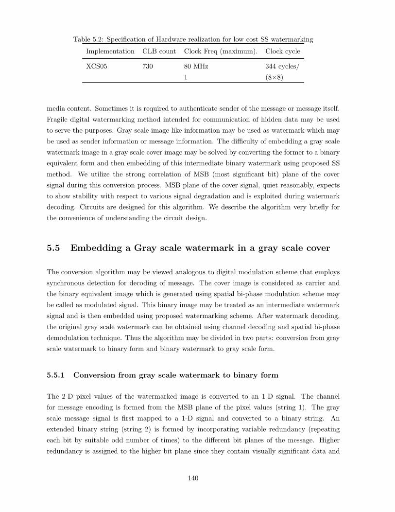
Table 5.2: Specification of Hardware realization for low cost SS watermarking
Implementation CLB count Clock Freq (maximum). Clock cycle
XCS05 730 80 MHz 344 cycles/
1 (8×8)
media content. Sometimes it is required to authenticate sender of the message or message itself.
Fragile digital watermarking method intended for communication of hidden data may be used
to serve the purposes. Gray scale image like information may be used as watermark which may
be used as sender information or message information. The difficulty of embedding a gray scale
watermark image in a gray scale cover image may be solved by converting the former to a binary
equivalent form and then embedding of this intermediate binary watermark using proposed SS
method. We utilize the strong correlation of MSB (most significant bit) plane of the cover
signal during this conversion process. MSB plane of the cover signal, quiet reasonably, expects
to show stability with respect to various signal degradation and is exploited during watermark
decoding. Circuits are designed for this algorithm. We describe the algorithm very briefly for
the convenience of understanding the circuit design.
5.5 Embedding a Gray scale watermark in a gray scale cover
The conversion algorithm may be viewed analogous to digital modulation scheme that employs
synchronous detection for decoding of message. The cover image is considered as carrier and
the binary equivalent image which is generated using spatial bi-phase modulation scheme may
be called as modulated signal. This binary image may be treated as an intermediate watermark
signal and is then embedded using proposed watermarking scheme. After watermark decoding,
the original gray scale watermark can be obtained using channel decoding and spatial bi-phase
demodulation technique. Thus the algorithm may be divided in two parts: conversion from gray
scale watermark to binary form and binary watermark to gray scale form.
5.5.1 Conversion from gray scale watermark to binary form
The 2-D pixel values of the watermarked image is converted to an 1-D signal. The channel
for message encoding is formed from the MSB plane of the pixel values (string 1). The gray
scale message signal is first mapped to a 1-D signal and converted to a binary string. An
extended binary string (string 2) is formed by incorporating variable redundancy (repeating
each bit by suitable odd number of times) to the different bit planes of the message. Higher
redundancy is assigned to the higher bit plane since they contain visually significant data and
140

less or no redundancy for lower order bit planes that contribute more subtle details in the image
[6]. Strings 1 and 2 are partitioned into sub strings having equal and fixed number of digits or
symbol. If there occurs more than 50% positional match of the symbols in the two respective
sub strings, a bit 1 is assigned for the sub string otherwise a bit 0. Bit 1 indicates in-phase
condition of two sub strings while out of phase condition is represented by bit 0. Assigning a
binary digit, corresponding to each substring of particular number of symbols, is called here as
spatial bi-phase modulation technique. The process converts a gray scale message into a binary
equivalent modulated signal.
5.5.2 Conversion from binary watermark to gray scale form
The 2-D pixel values of the watermarked image or its noisy versions are converted to 1-D string.
The MSB plane of this 1-D signal is picked up and partitioned into substrings of fixed and
equal number of symbols. Each substring either remains unchanged or complemented based on
the value of the detected intermediate binary watermark bit 1 or 0 respectively that represents
the particular substring. Each substring obtained after such operation is partitioned into sub
substrings (smaller substrings) based on the degree of redundancies incorporated on the different
message bits. Binary detection is then applied for each sub substring based on the majority
decision rule i.e. if more than 50% symbols of a sub-substring are 1, decision for decoding is
1 otherwise 0. The binary digits of all the sub substrings of a substring are then converted to
the pixel values for the decoded message. The similar decoding process is applied for other sub
strings and the conversion from binary to gray scale watermark is thus completed.
5.6 Circuit design for gray scale to binary watermark and binary
to gray scale watermark conversion[148]
There are two main modules namely (i) Conversion of gray scale watermark image to binary
equivalent form and (ii) reconversion of binary watermark to its gray scale version. We use
XILINX SPARTAN series FPGA for circuit design.
5.6.1 Gray scale watermark to binary watermark conversion
The VLSI architecture of the gray scale to binary watermark converter using the proposed
algorithm is shown in Fig. 5.14. The major sub blocks are control circuit, serial-in-parallel out
(SIPO) shift registers, multiplexer and majority encoder. In order to speed up the process, two
SIPO operates in parallel. When one SIPO takes external input data, the other SIPO feeds data
to the majority encoder unit and vice versa. Two data sets, each of sixteen bit length from the
141

two SIPO, are fed to the multiplexer that outputs one data set to the majority encoder block. In
the majority encoder block the other input is coming from the extended message obtained after
adding redundancy. Two data sets of 16 bit are fed into an array of 16 XNORs for similarity
comparison. The output from the similarity comparator block is then passed through parallel-
in-serial-out (PISO) shift register and fed into a 4 bit binary up counter to enable its clock. The
output of the counter is fed into an encoder. For a string of 16 bits, if the similarity comparator
output is 1 in 9 bit positions or more, then the counter value will be upgraded by the same
amount. The counter is reset after every 16 bit string. The counter value is fed to an encoder
block. The encoder is designed so that if its input value is nine or more, it will give at its output
1, otherwise 0. This encoder output is final modulated output which is the intermediate binary
watermark.
Figure 5.14: VLSI architecture of gray scale to binary watermark converter
Fig. 5.15 shows the detailed combinational logic for the encoder block. Here the output
from the PISO (Parallel-in-serial-out) shift register is used as the clock enable signal for the
4 bit counter. Thus whenever the output from the PISO shift register is 1, the output of the
counter is incremented by 1 value. In order to distinguish between two substrings of length 16
bits a ’Clr’ terminal is used for the counter to reset it after 16 clock cycles. The terminal count
of another 4 bit counter after being passed through a D flip-flop is fed to the ’Clr’ terminal.
Thus the majority encoder output ’Tout’ is obtained at an interval of 16 clock cycles with an
initial delay of 32 clock cycles.
142

Fig. 5.16 shows the detailed design of the control circuit. The circuit is basically used to
control the flow of data to the two serial-in-parallel-out shift registers. A 5 bit counter is used
together with some combinatorial circuit to generate the necessary control signals. The data
channel ’din’ is used as the input of the SIPO-1 for the first 16 clock cycles of the counter. At
the 16-th clock cycle the data channel ’din’ is transferred to the input of the SIPO-2 and the
enable signal meant for SIPO-1 is made high for one (1) clock cycle only. At the 31-st clock
cycle the enable-2 is obtained by passing the terminal count of the counter through a D flip-flop.
Thus as the counter again starts counting from zero the enable-2 line remains high for 1 clock
cycle only and the data channel is now transferred to SIPO-2. One set of data (of size 16 bits) is
read from the data file through one SIPO shift register, the previous set of data can be obtained
from another SIPO shift register and it leads to faster operation.
Figure 5.15: Circuit of Majority encoder block
143

Figure 5.16: Circuit of Control circuit
144

5.6.2 Binary watermark to gray scale watermark conversion
The VLSI architecture of the binary to gray scale watermark conversion method is shown in
Fig. 5.17. The main sub-blocks are (i) control unit, (ii) SIPO-1 and SIPO-2, (iii) controlled
complementer, and (iv) redundancy remover.Control unit, SIPO-1 and SIPO-2 work in same
fashion as in the gray scale to binary watermark conversion method.
The controlled complementer block consists of sixteen 2:1 multiplexer and sixteen inverters
to generate sixteen image bits. The design of the controlled complementer circuit is shown in
Fig. 5.18. The function of the multiplexer is to select any one out of two available input (let
A and B) at a time and send this to the output. Two 2-input AND gates (let G1 and G2)
and one 2-input OR gate (G3) perform the function. A is connected to the input terminal
of G1 and B is connected to the input terminal of G2. One select signal S is connected to
the second input terminal of G2 directly and in inverted manner to the second input termi-
nal of G1. The output terminals of G1 and G2 are connected to the two input terminals of
G3. When S=0, G1 yields A and G2 yields 0 due to basic AND operation. G3 will produce A
at the circuit output due to basic OR operation. By similar logic, when S=1 circuit output is B.
Figure 5.17: VLSI architecture of binary watermark to gray scale watermark
The controlled complementer circuit receives 16 data bits D[15:0] in parallel and coded bit
145

Tout as inputs. 16 data bits D0.....D15 are connected in parallel to the first input terminal of
the 16 multiplexers. Tout is connected to the select terminal of the muxs. Second input terminal
of each mux receives the inverted logic level of the first input. Each mux is designed in such a
manner that when select input is 1 the first input will be selected, otherwise the second input
will be selected. When Tout=1 it implies that data and images bits are the same, otherwise
opposite to one another. The logic reveals that when Tout=1 data bit appears at the output of
the circuit as the image bit. Thus 16 image bits F[15:0] are obtained from 16 multiplexers.
The output from the controlled complementer is fed to the redundancy remover unit. The
16-bit substring is divided into 4 parts of 9 bits, 5 bits and two lower bits. There are two 4 bit
counter, one for removing redundancy from 9 bits and the other one from the next 5 bit. The
string of 9 bits is fed to a counter to enable its clock and if the counter value is 5 or more, it
is further encoded to give an output 1, otherwise 0. Similarly, redundancy is removed from the
bit string of five bits. Thus each substring of 16 bit is converted to a 4 bit after redundancy
removal. By converting each 16 bit substring to 4 bit string, the image is decoded.
The hardware design is implemented using XILINX SPARTAN series FPGA. The chip used
is XCS05 which contains 100 CLB (configurable logic block) out of which 85 are consumed, 40
CLBs for the transmitter and 45 CLBs for the receiver. Important specifications are summarized
below in Table 5.2.
Table 5.3: Specification of Hardware realization for gray scale cover & gray scale watermark
image
Implemen- CLB clock freq. clock
tation count (max) cycle
XCS05 85 80 MHz 17 cycles/message
pixel value (4 bits)
146

Figure 5.18: Circuit of Controlled complementer circuit
The proposed SS watermarking scheme and the two sets of circuits are well suited for dynamic
estimation of wireless channel condition, QoS assessment of offered services in mobile radio
environment, secured communication and integrity verification of digital media.
147
5.7 Conclusions
In this chapter we have presented our studies on development of fragile spread spectrum wa-
termarking using unitary transform. Fast Walsh (or Hadamard) transform is used due to its
advantages of low cost of computation i.e. ease of hardware implementation and resiliency
against JPEG and JPEG 2000 compression. Circuits are designed using XILINX SPARTAN
series FPGA. The algorithm is tested for dynamic estimation of wireless channel condition . An
efficient algorithm for converting a gray scale watermark to a binary equivalent form and its
appropriate gray scale equivalent form have been proposed. Circuits are also designed for the
algorithm. The algorithm may be used to authenticate sender as well as secured communication
of the message.
Although we have developed fragile SS watermarking methods to cater particular application
in this chapter, but SS modulation principle is mainly used to design robust SS watermarking.
With this in mind, we are going to investigate how to improve robustness performance of SS
watermarking scheme both analytically as well as algorithmically in the next chapter.
148
Chapter 6
Spread Spectrum Watermarking for
Robustness and Capacity
Improvement
6.1 Introduction
Mathematical analysis of SS watermark decoding shows that one of the most important factor
that affects robustness performance leading to unreliable detection is the residual correlation
between the host signal and the watermark. The robustness performance is also affected in
high payload system due to multiple bit interference (MBI) effect arising out from large cross-
correlation values among the code patterns. The space-frequency transform, due to its co-joint
representation, multiresolution analysis, directional decomposition and better space-frequency
tiling can reduce the effect of host signal interference. Decomposition in multiple directions
may distribute the payload capacity and improve robustness by reducing the effect of mulibit
interference. Discrete wavelet transform is a promising space-spatial frequency transform and is
used widely in various applications such as compression, signal detection and denoising. Thus
this transform and its variant become a natural choice for designing robust watermarking.
The objective of this chapter is to develop robust SS watermarking methods with improved
payload capacity. It begins with robustness analysis of SS watermarking and based on the
results new watermarking techniques are proposed. Some of the factors responsible for robust-
ness improvement are determined and their effect on robustness improvement are discussed
mathematically. Reduction in host signal interference is better achieved using space-frequency
transform compared to unitary transform. So a discussion is made on relative importance and
relevance of space-spatial frequency transform for analysis of nonstationary signal compared
to global frequency analysis offered by Fourier transform. Brief description of DWT, BiDWT
149

(biorthogonal dyadic wavelet transform), and M-band wavelets are then presented. The effect of
choice of signal decomposition tools and choice of subbands on robustness improvement are then
discussed. Factors responsible for improvement in payload capacity are also analyzed in con-
nection with robustness improvement. Four SS watermarking algorithms using DWT, BiDWT,
M-band wavelets and Hilbert transform designed from biorhogonal wavelet bases are also pro-
posed. DWT based algorithm (Algorithm 1) uses CDMA scheme for payload improvement using
signal adaptive technique. BiDWT based algorithm (Algorithm 2) serves the dual purposes of
authentication and blind assessment of QoS for multimedia signal transmitted through wireless
channel. M-band wavelet based algorithm (Algorithm 3) employs a novel channel coding scheme
and N-ary modulation principle for the performance improvement in SS watermarking. The in-
vestigation has shown that the higher computation cost for decoding with high N-values can
be compensated if moderate values of M is used while robustness performance may be main-
tained at satisfactory level. Finally, QCM based SS watermarking technique using wavelet based
Hilbert transform (Algorithm 4) has shown that how watermark embedding process improves
payload capacity by two times with almost no change in data imperceptibility. Experimental
results show that watermark decoding from both the decompositions are affected in the similar
fashion over a wide range of signal degradation.
6.2 Design of Robust Spread Spectrum Watermarking[157, 158]
Mathematical models of SS watermark embedding and decoding presented in section 5.2 high-
light the following major shortcomings:
1. Large bandwidth requirement of SS scheme does not facilitate the extraction of long bit
sequence and does not allow high embedding capacity.
2. Residual correlation between the host signal and the watermark results an unreliable
detection when watermark energy is reduced arising out from near-far problem. In watermarking,
near-far problems indicate relative strength of the different embedded watermark signature.
3. SS approaches are not adaptive and attack interference are not radially incorporated to
estimate statistical variance. The correlation receiver structure are not effective in the presence
of fading-like distortion.
4. The factors responsible for robustness improvement do not get due importance in the
reported SS watermarking schemes.
In the following subsections we discuss the effect of few factors that are responsible for
greater robustness and capacity aspects of SS watermarking schemes which will also take care
other issues as stated earlier. We conjure that the detection reliability (robustness) improvement
depends on (1) development of spreading codes with specific properties, (2) signaling scheme,
150

binary or M -ary (3) determination of embedding strength, (4) the selection of modulation func-
tion for adaptive watermarking, (5) the choice of particular transform coefficients for better
spectrum spreading for the embedded data, (6) direction of decompositions etc.
6.2.1 Properties of Code Patterns and their design
Equation (5.10) which results from equation (5.4) and improvement in detection reliability under
multiple bit embedding show that the codes should satisfy the following properties [179].
(1) Pi, i=1,2, ... M, should be distinct sequences with zero average.
(2) The spatial correlations < Pi, Pj >,j �= i should be minimum. Ideally, sequences Pi and Pj
should be orthogonal whenever j �= i.
(3) If image prediction (for estimating the image distortion) is not used before evaluating the
cross-correlation it is desirable that Pi’s (for i=1,2,....M) should be uncorrelated with the image
block I.
(4) Spatial correlation α. < Pi, bi.Pi > should be maximized although detcetion reliability and
image distortion must be properly trade-off.
Pseudo random or pseudo noise (PN) sequences satisfy property (1) and (2) if only infinite length
sequence is considered which is not feasible for practical image processing operations. Mayer
et al. [179] showed that robustness is improved for small size image block if spreading codes
are generated from Hadamard basis and by Gram-Schmidt orthogonalization of pseudo random
sequences. But under this circumstance the following problems may arise: (1) unauthorized de-
coding and possible removal of the embedded data due to the deterministic nature of Hadamard
basis; (2) Better spectrum spreading is not possible for small size image block. SS watermarking
techniques that have been developed and discussed in this thesis solve this problem by modulat-
ing the code patterns using Hadamard basis function. Each PN code is exclusive-ORed with a
row of Hadamard matrix of proper dimension. Property (3) can be satisfied provided the cover
signal is properly decomposed so that it yeilds low correlation with the code patterns. Property
(4) is satisfied by the choice of the value of embedding strength.
6.2.2 Determination of Watermark Embedding Strength
It is already mentioned in the property (4) of the code pattern that the higher the value of spa-
tial correlation α. < Pi, bi.Pi >, higher will be the robustness performance of SS watermarking.
The high spatial correlation value is obtained if α- value i.e. the modulation index for embed-
ding or embedding strength is high. But the high value of embedding strength causes large
image impairment for the watermarked image. To make a good trade-off between robustness
performance and image impairment, signal adaptive watermarking scheme would be efficient
which we have discussed in the immediate next subsection. The adaptive α-value i.e. when
151

embedding strength is a function of image coefficient we need to calculate different α-values
for different image coefficients, and computation cost for embedding is expected to be high. A
good compromise in that case may be selection of a particular α-value for a subband or set of
subbands unlike the signal adaptive case. We now provide a guideline to find what should be
the embedding strength for different subbands based on their variance values.
Embedding strength is determined considering Mean Structural SIMilarity (MSSIM) index
as an objective measure to quantify visual quality of the watermarked image with respect to
the cover. Watermark embedding is additive in nature in code based SS techniques and we
denote the amount of data embedding in each coefficient value (xi) of the cover image (X) by
∆xi. Following the Equations (4.24) and (4.25), the structure comparison function after data
embedding in an image block can be written as follows:
s(x, y) =1
N − 1[
N∑i=1
(xi − µx)2 +N∑
i=1
(xi − µx)(∆x− µ∆x)] (6.1)
In most cases (∑N
i=1|(xi−µx)|) value is greater for high variance image coefficient block than the
low variance one. Equation (6.2) shows that (∆x − µ∆x) value i.e. watermark strength factor
should be smaller for high variance image coefficient block than the low variance one in order
to preserve s(x, y) value same in both cases.
6.2.3 Signal Adaptive Spread Spectrum Watermarking
The main idea behind the improvement in detection reliability is to exploit the knowledge about
the signal X (or more precisely, x, the projection of X on the watermark) and accordingly to
modulate the energy of the inserted watermark in order to compensate for the signal interference.
To accomplish this signal adaptive SS watermarking, we vary the amplitude of the inserted chip
sequence by using linear and power-law transformation functions. It is found that under a fixed
attack distortion, better detection reliability in such cases is possible compared to conventional
signal non-adaptive SS scheme. We now have three different forms of watermarked image as
follows:
X′= X + k.[Pi] (6.2)
X′= X + k1.X.[Pi] (6.3)
X′= X +Xµ[Pi] (6.4)
Equation (6.3) represents conventional signal non adaptive SS watermarking (additive) scheme
where as Equations (6.4) and (6.5) are signal adaptive SS watermarking (multiplicative) schemes
using linear and power-law modulation functions respectively.
152

In all the above equations X′
represents watermarked image coefficients, X are image co-
efficients, Pi is the code pattern with length equal to the image block, k is the gain factor or
modulation index, k1 is the ratio of minimum image coefficient to maximum image coefficient - a
negative quantity, µ is the modulation index in power-law modulation function. The modulation
index µ is negative numeric quantity with value less than 1.
Detection reliability in each case is determined by the stability of the decision variable tiwith respect to a given attack distortion. Similar to the Equation (5.9), the expression of ti for
a particular Pi, is rewritten here for convenience of our further analysis.
ti =< X′, Pi >= 1/M < Xl
′, Pil > (6.5)
where l is the length of the sequence. If we substitute the values of X′from the equations (6.3),
(6.4) and (6.5) into the equation (6.6), the expressions of ti become as follows respectively:
ti = 1/MM∑l=1
(Xl + k.Pil)(Pil) = 1/MM∑l=1
(Xl.Pil + k.P 2il) (6.6)
ti1 = 1/MM∑l=1
(Xl + k1.Xl.Pil)(Pil) = 1/MM∑l=1
(Xl.Pil + ki.Xl.P2il) (6.7)
ti2 = 1/MM∑l=1
(Xl +Xlµ.Pil)(Pil) = 1/M
M∑l=1
(Xl.Pil +Xlµ.P 2
il) (6.8)
It is already shown that improved detection requires zero averaging sequence i.e in the code
pattern number of zero should be equal to the number of one. Differentiating Equations (6.7),
(6.8) and (6.9) with respect to Xl and invoking the above property of the code pattern, we have
the expressions for dti/dXl respectively as follows:
dti/dXl = 1/MM∑l=1
Pil = 1/M(0.M/2 + 1.M/2) = 1/2 (6.9)
dti1/dXl = 1/MM∑l=1
Pil + 1/MM∑l=1
P 2il = 1/2 + k1/M(0.M/2 + 1.M/2) = (1 + k1)/2 (6.10)
dti2/dXl = 1/MM∑l=1
Pil + µ/MM∑l=1
Xlµ−1.P 2
il = 1/2 + µ/MM∑l=1
Xlµ−1.P 2
il (6.11)
We have defined k1 = Xl(min)/Xl(max) in Equation (6.11), a negative quantity and let k1 =
−k2 where 0 < k2 < 1. If we substitute k1 = −k2, the expression of dti/dXl for the equation
becomes as follows:
dti1/dXl = (1 − k2)/2 < dti/dXl (6.12)
In Equations (6.10), (6.12) and (6.13) dti/dXl denote the change of decision variable ti with
respect to the change of Xl i.e. a measure of noise immunity in the detection process. Lower
value of dti/dXl indicates better detection reliability.
153

6.2.4 M-ary Signaling Scheme[173]
In digital communication, information is transmitted as symbol and the symbol may consists
of m number of bits (M-ary signalling, M > 2) where M = 2m or single bit (binary signalling)
with two possible values, either 0 or 1. Now the use of M -ary modulation in SS watermarking
is discussed in the following paragraphs.
It is already mentioned that distinct code pattern is used to embed each bit or symbols in
SS technique. In M -ary modulation, a group of symbols are treated as single entity and for
a fixed length binary message less and less number of code patterns will be added with the
signal points as M - value increases. Higher M value gives rise to the scope of choosing higher
modulation index values for a fixed allowable distortion. M set distinct code patterns with each
set containing N number spreading functions are generated. We denote the whole set by Pi
where i = 1, 2, ..M . The value of M depends on the number of bits required to represent a
symbol and the value of N equals to the total number of symbols that the watermark contains.
M -ary (M > 2) demodulation process decodes a m bits symbol (where M = 2m) corre-
sponding to each position of the respective symbol message. Watermark symbols are decoded
sequentially. To decode a symbol at the particular position, correlation values are calculated
between the watermarked coefficients and the spreading functions of the respective positions for
all the sets of the keys. Let us assume that we want to decode a message symbol occurred in
the 1st (first) position. Correlation values are calculated between the watermarked coefficients
and the spreading functions that occurred in the first position for all the sets respectively. The
index of the largest correlation coefficient i.e. the particular set of key whose 1st spreading
function yields the maximum correlation value determines the decoded symbol. In the follow-
ing paragraphs we calculate the average probability of symbol error in M -ary SS watermark
decoding.
The watermarked image after embedding N number symbols can be expressed as follows:
X′l =
N∑i=1
L∑l=1
(Xl + α.Sil) (6.13)
where ’l’ corresponds to the length of the signal to be watermarked, α is the embedding strength,
Sil indicates spreading functions for different i values. The decision criteria that minimizes
the average probability of symbol error is indicated by Zk where Zk =< X′l , Skl > would be
maximum with respect to each k. Probability of symbol error is expressed as follows:
PE =M∑i=1
P [E | Si embedded] P [Si embedded] = 1/Mi=M∑i=1
P [E | Si embedded] (6.14)
where each symbol is assumed apriori equally possible. We may write
P [E | Si embedded] = 1 − Pci (6.15)
154

where Pci is the probability of a correct decision given that Si was embedded.
A correct decision for the symbol of i-th position results only if,
Zj =< X′l , Sjl >< Zi =< X
′l , Sil > (6.16)
for all j �= i, Pci can be written as
Pci = P ( all Zj < Zi, j �= i) (6.17)
If Zi and ri represents the decision statistics for i-th symbol when all N symbols and only the
i-th symbol is embedded respectively. Then we may write Zi as follows:
Zi =N∑
j=1j �=0
L∑l=1
(Xl + α.Sil)Sil +∑l=l
L∑l=1
(Xl + α.Sil)Sil = rji + ri = Yi + ri (6.18)
rji, is the decision statistics for j-th embedded symbol when correlated with i-th symbols’s
spreading function. If the i-th symbol is correctly decoded, it follows that Equation (6.17)
becomes
Pci = P ( all Yi < ri, j �= i) (6.19)
Under the assumption of large image size we may use central limit theorem and conclude that
Yi approaches a Gaussian distribution with mean and variance calculated as follows.
Mean[Yi] = E[N∑
j=1j �=i
L∑l=1
(Xl + α.Sil)Sil] = 0 (6.20)
and
V ar[Yi] = E[N∑
j=1j �=i
L∑l=1
(Xl + α.Sil)Sil]2 =N∑
j=1j �=i
[‖ X ‖2 +α2.L]E[S2il]
= (N − 1)[‖ X ‖2 +α2.L] = V0/2 (6.21)
Furthermore, Yi and Yj , for i �= j, are independent, since E[YiYj] = 0. Given a particular value
of Yi, Equation (6.19) becomes
Pci(Yi) =M∏
j=1,j �=i
P [Yj < ri] =(∫ ri
−∞e
−y2j
/v0√π.v0 dyj
)M−1
(6.22)
which follows because the pdf of Yj is y(0,√v0/2). Averaged over all possible values of Yi,
Equation (6.22) gives
Pci =(∫ ∞
−∞e
−y2i
/v0√π.v0
(∫ ri
−∞e
−y2i
/v0√π.v0 dyj
)M−1
dyi = (π)−M/2∫ ∞
−∞e−b2
(∫ a√
v0
∞e−x2
da
)M−1
db(6.23)
where a = yj√v0
= ri√v0
i.e. ri = a√v0, b = yj√
v0. Since Pci is independent of i, it follows that the
probability of error is
PE = 1 − Pci (6.24)
155

with Equation (6.23) substituted in Equation (6.24), a non-integrable M-fold integral for PE
results, and one must resort to numerical integration to evaluate it.
In this section we discuss the effect of some factors which are responsible for robustness
improvement in SS watermarking. The most degrading effect for SS watermark detection is
the host signal interference which can be reduced by proper directional decomposition of the
cover image. This attribute is not satisfied properly using unitary transform and space-spatial
frequency transform becomes promising alternative. In the next subsection we describe space-
spatial frequency transformation.
6.3 Space-Spatial Frequency Transformation
An important issue in the analysis of signals is their representation. The representation should
be such that any kind of information required, can be easily accessible from it. For instance, in
signal analysis it is very often necessary to study the frequency content of a signal. One of the
classical tools to extract such information is the Fourier analysis, which maps a signal f(t) from
the time domain to the frequency domain (global). In case of images, if represented in spatial
domain as f(x, y), the corresponding frequency domain representation is F (u, v). The Fourier
Transform assumes that the signal to be analyzed is either of infinite duration or is at least of
one complete period. Fourier analysis works for the frequency domain description of stationary
signal and is not appropriate for the analysis of non stationary signal i.e. is not able to convey
which frequency is present during what intervals of time. This points out the need for a localized
time-frequency (space-spatial frequency for image) representation of the signal to be analyzed.
One simple way to obtain such a representation is to place a localized window on the signal
which is shifted along the time axis and to perform a Fourier Transform at each point in time.
This yields the Windowed Fourier Transform (WFT). Reference to the equation (4.1), the WFT
for a one dimensional (1D) continuous time signal, will be
WF (u, T ) =∫ ∞
−∞f(t)g(t− T )e−2πiutdt (6.25)
where u represents the frequency, g(t) is a window function centered around T. Whereas the
classical Fourier analysis uses the plain waves e−2πiut ( the so called analyzing functions) as
the elementary “building blocks” to decompose the signal, the WFT uses the set GuT (t) =
g(t− T )e−2πiut which maps the signal on a two-dimensional (2D) representation which is time-
frequency plane. The coefficient WF (u, T ) will have large magnitude when the signal f(t) re-
sembles the coefficients of a member of the analyzing function (i.e. similar time localization of
frequency content).
We can see that the WFT is the inner product of f(t) with a set of functions
Gu,T = g(t− T )e−2πiut (6.26)
156

The window function, g(t) should be long enough so that the product f(t)g(t) contains some
useful frequency elements in the application under study. But this function cannot be too long
as it defeat the idea of localization in time.
The main drawback of the WFT is that once the width of the window function is decided
it does not change during the entire duration of a particular analysis and it will have a fixed
resolution in frequency, because the time resolution is fixed. Fig. 6.1(a) schematically shows
the tiling of the time-frequency plane of WFT. It is not possible to obtain simultaneously the
same degree of accuracy for localization in time and frequency known as principle of uncertainty
in signal analysis. The blocks tiling the time-frequency plane all have the same area and thus,
once the width of the window g(t) is chosen, this tiling is fixed.
The wavelet transform is another time-frequency representation for signals having multires-
olution properties. One might desire to study the slowly varying properties of signal (low
frequencies) over a longer time span and vice versa for the high frequencies, for those purposes
the wavelet is best suited. Fig. 6.1(b) shows the time-frequency tiling of wavelets employed as
analyzing functions. The wavelet transform decomposes a signal into its “wavelets coefficients”,
which are the scaled and shifted versions of the “mother wavelet”. The translation and dilation
parameters of the the mother wavelet are varied to generate the wavelet coefficients, with which
the correlation between the wavelet and a localized section of the signal is computed.
Figure 6.1: Tiling of the time frequency plane: (a) as obtained by the WFT (b) as obtained by
the wavelet transform
In the last decade, wavelet theory has emerged, as a powerful tool. It has provided a promising
alternative through multichannel filter banks that have several useful advantages:
1. Wavelet filters cover exactly the complete frequency domain.
2. The wavelet expansion allows a more accurate local description and separation of the signal
characteristics. The wavelet expansion may allow a separation of components of a signal that
overlap in both time (space) and frequency (spatial-frequency).
3.Wavelets are adjustable and adaptable. Due to the flexibility of choosing the form of mother
157

wavelets, they can be designed to fit individual applications. They are ideal for adaptive systems
that adjust themselves to suit the signal.
In the following three subsections, we describe briefly 2-band or dyadic discrete wavelets
(DWT), 2-band Biorthogonal Discrete wavelets (BiDWT) and M-band wavelets. These three
different forms of wavelets are studied for designing robust Spread Spectrum (SS) watermarking
schemes.
6.3.1 Discrete wavelet transform
The wavelet decomposition can be interpreted as signal decomposition in a set of independent,
spatially oriented frequency channels. It turns out that the wavelet coefficients can be computed
by iterative filtering of the signal [234]. Under these constraints an efficient real space imple-
mentation of the transform using quadrature mirror filter (QMF) exists [19, 272]. This consists
of a lowpass filter h and a highpass 1filter g which are related to the bases of Vi (spaces spanned
by the scaling functions at different resolution) and Wi (spaces spanned by wavelet functions)
respectively. From the requirement that the wavelets span the “difference” or orthogonal com-
plement spaces, and the orthogonality of integer translates of the wavelet (scaling) function, it
can be shown that the wavelet coefficients (modulo translations by integers of two) are required
by orthogonality to be related to the scaling function coefficients (QMF) by
g(k) = (−1)kh(1 − k) (6.27)
Further they apply the mirror filters h and g defined by
h(k) = h(−k)and g(k) = g(−k).
The discrete normalized scaling φj,k and wavelet ψj,k basis functions are defined as
φj,k(t) = 2−j/2hj(2−jt− k) (6.28)
ψj,k(t) = 2−j/2gj(2−jt− k) (6.29)
where j and k are respectively the dilation and translation parameters and hj and gj are
respectively the sequence of lowpass and bandpass filters of increasing width indexed by j, which
are expanded by inserting an appropriate number of zeros between filter taps (filter coefficient).
They satisfy the quadrature mirror filter condition and are called the analysis (synthesis) filters.1Strictly speaking, g is a bandpass filter, but since it captures all the remaining high frequencies of the signal,
it is commonly called a high pass filter.
158

The full discrete wavelet expansion of a signal f(t) ∈ l2(l2 is the space of square summable
functions) is given by
f(t) =∑k
LJ(k)φJ,k(t) +J∑
j=1
∑k
Dj(k)ψj,k(t) (6.30)
The first term in this expression is the low resolution signal LJ(k); and the coefficients Dj(k) con-
stitute the detail signal at scale j for k ∈ z. The whole of wavelet coefficients {LJ , {Dj}1≤j≤J}is called the wavelet representation at depth J of signal f.
The extension of this method to image f(x, y) is usually performed by taking the tensor
products of the spaces Vj and Wj and their corresponding bases. This approach has the benefit
that the transform can be implemented by filtering with the one-dimensional quadrature mirror
filters along the rows and columns of the image. Fig. 6.2 represents the scheme. In each filtering
step we now have a low resolution image Lj and three detail images Dj1, Dj
2 and Dj3. Since
the detail images are obtained by applying the lowpass and /or highpass filters along rows and
columns, they contain the vertical (Dj1), horizontal (Dj
2) and (Dj3) detail of the original images
at a certain scale j.
The computation of the 2D extension of DWT is obtained in two steps by successive ap-
plication of the 1D filtering along rows and columns of an image (Fig.6.3 ) (i.e., by applying a
separable filter bank to the image). These are
Lj(x, y) = [hj−1,x ∗ [hj−1,y ∗ Lj−1]↓2,1]↓1,2(x, y) (6.31)
Dj1(x, y) = [hj−1,x ∗ [gj−1,y ∗ Lj−1]↓2,1]↓1,2(x, y) (6.32)
Dj2(x, y) = [gj−1,x ∗ [hj−1,y ∗ Lj−1]↓2,1]↓1,2(x, y) (6.33)
Dj3(x, y) = [gj−1,x ∗ [hj−1,y ∗ Lj−1]↓2,1]↓1,2(x, y) (6.34)
where, ∗ denotes the convolution operator, ↓ 2, 1(↓ 1, 2)) denote subsampling along the rows
(columns) and L0 = I(x, y) the original 2D signal. hj,x(gj,x) and hj,y(gj,y) are the lowpass
(bandpass) filtering along x and y directions respectively for different scale.
159

Figure 6.2: (a) Decomposition (b) reconstruction schemes for computation of the wavelet co-
efficients in 2 dimensions using quadrature mirror filters, ∗ denotes convolution and 2↓ (2↑)downsmapling (upsampling) of the rows and columns by a factor of 2
Figure 6.3: Separable filtering for 2D discrete wavelet transform
160

Lj(x, y) corresponds to the lower frequencies. Djn are obtained by bandpass filtering in a
specific direction and thus contain the detail information at scale j. Dj1 corresponds to the
vertical high frequencies (horizontal edges), Dj2 the horizontal high frequencies (vertical edges)
and Dj3 the high frequencies in both direction (the corners). I(x, y) is represented at several
scales by, {LJ ,Dnj | n = 1, 2, 3, j = 1, ...., J}. Fig. 6.4 depicts the typical organization of these
images and an example of a wavelet transformed image.
Figure 6.4: (a) Typical organization of the detail images within the wavelet transform (b)
Example of a wavelet transform of the Lena image depth (3)
6.3.2 Biorthogonal wavelets
In many filtering applications we need filters with symmetrical coefficients to achieve linear
phase. None of the orthogonal wavelet system except Haar are having symmetrical coefficients.
But Haar is too inadequate for many practical applications. Biorthogonal wavelet system can
be designed to have this property [252]. This is why, in the present thesis, attempts have been
made for designing such wavelet system. Non-zero coefficients in analysis filters and synthesis
filters are not same i.e. the wavelet used for the analysis is different from the one used at the
synthesis.
Let
φ(t) =N−1∑k=0
√2h(k)φ(2t − k) (6.35)
and its translates form the primal scaling function basis and corresponding space be V0. Let
φ(t) =N−1∑k=0
√2h(k)φ(2t− k) (6.36)
161

and translates form the dual scaling function basis and corresponding space be V0. This means
that φ(t) and its translates are not orthogonal among themselves but orthogonal to translates
of φ(t) (except one basis function as in vector space) such that
φ(t− k)⊥φ(t−m) for every k �= m
which in turn means ∫φ(t− k)φ(t− k)dt = 0 for every k �= m
Also we need that, like in vector space, projecting φ(t − k) onto φ(t − k) should result in
unity. That is ∫φ(t− k)φ(t− k)dt = 1 for every k.
These two conditions together we put as :
∫φ(t)φ(t) = δk,0 (6.37)
Like scaling functions, wavelet function also follow the scaling relation given by
ψ(t) =∑
k g(k)√
2φ(2t− k) and
ψ(t) =∑k
g(k)√
2φ(2t− k) (6.38)
In orthogonal wavelet system, φ(t) is orthogonal to ψ(t) and its translates. In biorthogonal
system our requirement is that φ(t) be orthogonal to ψ(t) and its translates. Similarly φ(t)
must be orthogonal to ψ(t) and its translates. Since φ(t)⊥ψ(t), ψ(t) can be written as:
ψ(t) =N−1∑k=0
(−1)nh(N − k − 1)φ(2t− k) (6.39)
The condition φ(t)⊥ψ(t) relates g(k) with h(k). g(k) becomes alternate flip of h(k). The
derivation of the result follows in the same line as in the orthogonal wavelets.
ψ(t) =N−1∑k=0
(−1)nh(N − k − 1)φ(2t− k) (6.40)
Let ψ(t) and its translates span the space W0 and ψ(t) and its translates span the space
W0. Like primal and dual scaling functions, ψ(t) is not orthogonal to its own translates but are
orthogonal to translates of ψ(t), that is,∫ψ(t− k)ψ(t−m)dt = δk−m (6.41)
In orthogonal wavelet system ψ(t) is orthogonal to any scaled version of itself and its translates,
that is, ∫ψ(t− k)2j/2ψ(2jt−m)dt = δj,k−m (6.42)
162

The integral is zero except when j = 0 and k = m. When j = 0 and k = m, the integral becomes∫ψ(t)ψ(t)dt = 1
So in biorthogonal system, the most general equation connecting ψ(t) and ψ(t) is:∫ψj,k(t)ψj′ ,k′(t)dt = δj−j′δk−k′
If in addition the family is complete in a given space such as l2(R), then any function of the
space can be written as
f(t) =∑m
∑n
〈ψm,n, f〉ψm,n(t) =∑m
∑n
〈ψm,n, f〉ψm,n(t) (6.43)
since ψ and ψ play dual roles. There are various ways to find such biorthogonal families. For
example, one could construct a biorthogonal spline basis by simply not orthogonalizing the
Battle-Lemarie wavelet.
Another approach consists in starting with a biorthogonal filter bank and using the iterated
filter bank method just as in the orthogonal case. Now, both the analysis and synthesis filters
(which are not just time-reversed versions of each other) have to be iterated. For example,
one can use finite-length linear phase filters and obtain wavelets with symmetries and compact
support (which is impossible in the orthogonal case).
In a biorthogonal filter bank with analysis/synthesis filters H0(z),H1(z), G0(z), and G1(z)
Perfect reconstruction with FIR filters [234] means that
G0(z)H0(z) +G0(−z)H0(−z) = 2 (6.44)
and
H1(z) = −z2k+1G0(−z) (6.45)
G1(z) = −z2k−1H0(−z) (6.46)
Now, given a polynomial P (z) satisfying P (z) + P (−z) = 2, we can factor it into P (z) =
G0(z)H0(z) and use {H0(z), G0(z)} as the analysis/synthesis lowpass filters of a biorthogonal
perfect reconstruction filter bank.
We can iterate such a biorthogonal filter bank on the lowpass channel and find equivalent
iterated filter impulse responses. It is to be noted that analysis/synthesis impulse responses are
not simply time-reversed versions of each other (as in the orthogonal case), but are typically
very different (since they depend on H0(z) and G0(z), respectively). We can define the iterated
lowpass filters as
H(i)0 =
∏i−1k=0H0(z2k)
G(i)0 =
∏i−1k=0G0(z2k)
163

We now end our discussion by putting relations in biorthogonal wavelet systems in one place.
We have the following relationships:
1. V1 ⊂ V0 ⊂ V1 ⊂ .... ⊂ V∞2.V1 ⊂ V0 ⊂ V1 ⊂ .... ⊂ V∞whereVj =spank{2j/2φ(2jt− k)} and Vj =spank{2j/2φ(2jt− k)}3. In orthogonal wavelet system we have Vj orthogonal to Wj. But in biorthogonal system Vj
is orthogonal only to Wj . Similarly, Vj is orthogonal only to Wj .
4. Wk⊥Wj.
5. If x[n] ∈ l2(R) and X[k] is the transform of x[n], an important property of orthogonal
expansions is conservation of energy, i.e. ‖ x ‖2 = ‖ X ‖2.
In the biorthogonal case, conservation of energy can be expressed as [273]
‖ x ‖2 = 〈X[k], X [k]〉where X[k] = 〈ψk[l], x[l]〉 and (X[k] = 〈ψk[l], x[l]〉 are the transform coefficients of x[n] with
respect to {ψk} and {ψk}.
In this thesis, we exploit directional property of biorthogonal decomposition for improvement
in robustness performance of DS-SS (Direct Sequence Spread Spectrum) watermarking. More-
over, sharing of energy among the coefficients of biorthogonal decompositions help to design
robust as well as fragile watermarking schemes. More importantly, biorthogonal wavelets have
been used to design efficient Hilbert transform pair. Hilbert transform pairs are then used to
design QCM (Quadrature carrier multiplexing) based SS watermarking schemes that doubles
payload capacity with almost no change in cover image visual quality caused by data insertion.
6.3.3 M-band wavelets
M-band wavelets are a direct generalization of the conventional 2-band wavelets, where, M can
have any value larger than 2. Part of the motivation for a larger M comes from a desire to have
a more flexible tiling of the time-scale plane than that resulting from the standard M = 2 band
wavelet. It also comes from the desire to have some regions of uniform band widths rather than
logarithmic spacing of the frequency responses for 2-band system. An M -band wavelet system
form a tight frame for the set of square integrable functions defined over the set of real numbers
L2(R).
Let φ(t) be a more general multiresolution formulation of the scaling function satisfying,
φ(t) =∑k
h(k)√Mφ(Mt− k)
where the sequence h(k) is the scaling filter and satisfies the following linear and quadratic
164

constraints, ∑k
h(k) =√M (6.48)
and
∑k
h(k)h(k +ML) = δ(l) (6.49)
Additionally there are M−1 wavelets associated with the scaling function and satisfy
ψ(i)(t) =∑k
√Mg(i)(k)ψ(Mt − k), i = 1, ...,M − 1. (6.50)
g(i)(k) vectors called the wavelet filters satisfy the equation,
∑k
g(i)(k)g(i1)(k +Ml) = δ(l)δ(i − i1) (6.51)
In the discrete form these equations can also be written as
φjk(t) =∑k
M−j/2φ(M−jt− k) (6.52)
and
ψ(i)jk (t) =
∑k
M−j/2ψ(i)(M−jt− k), i = 1, .....,M − 1. (6.53)
For any function f(t) ∈ L2(R), it can be shown that
f(t) =i=M−1∑
i=1
∑j∈Z
∑k∈Z
〈f(t), ψ(i)j,k(t)〉ψj,k(i)(t) (6.54)
where Z represents the set of integers and 〈, 〉 is the inner product operator.
A function f(t) ⊂ L2(R) can be constructed from a discrete sequence a(k) ∈ l2(R) in the
form,
f(t) =∑k
a(k)φ(t− k) (6.55)
The function f(t) can also be expressed in terms of the sum of projections onto subspaces Vi
(spanned by the functions φik(t)) and W ji (spanned by the functions ψj
ik(t)) as,
f(t) =∑k
L(k)φj,k(t) +M−1∑j=1
∑k
Dj(k)ψij,k(t) (6.56)
The expansion coefficients can be expressed as,
L(k) = 〈f, φj,k〉,Dj(k) = 〈f, ψ(i)
j,k〉, i = 1, 2.......,M − 1. (6.57)
165

It can be shown that,
L(k) = 1/√M
∑l
a(l)h(Mk − l), (6.58)
D(i)(k) =∑
l
a(l)h(i)(Mk − l), (6.59)
which is equivalent to processing the sequence a(k) with a set of linear space-invariant filters of
impulse response pi = 1/√Mg(i)(k) and down sampling filter outputs by M.
Figure 6.5: M-band filter bank structure (M = 4)
Fig. 6.5 shows a typical M -band filter bank. An important aspect of M -band is that, a given
scaling filter h specifies a unique φ(t) and consequently a unique multiresolution analysis. For
example with M = 4,
V0 =V1⊕W11⊕W21⊕W31,V1 =V2⊕W12⊕W22⊕W32
where V ,j s are the spaces spanned by the scaling function at different resolution and W ,
js are the
spaces spanned by the wavelet functions. The scale-space tiling for M -band wavelet (M = 4) is
166

depicted in Fig. 6.6(b).
Figure 6.6: Basis tiling in (a) M(=2)-band and (b) M(=4)-band wavelet
With brief introduction of various wavelets we now turn our attention for robust SS water-
mark design using the wavelets.
6.4 Robustness improvement using wavelets
In this section we will discuss how different wavelets can be used to improve robustness per-
formance in SS watermarking. Two major points to be discussed are: (a) choice of signal
decomposition tool and (b) selection of subbands for better spectrum spreading of the hidden
data.
6.4.1 Choice of Signal Decomposition Tool
In wavelet transform, flexibility in space-frequency tiling offers proper selection of subbands
in order to realize better spectrum spreading of the embedded watermark. We have studied
the performance of SS watermarking scheme using 2-band discrete wavelet transform (2-DWT),
biorhtogonal 2-band discrete wavelet transform (BiDWT) and M-band discrete wavelet trans-
form (MbDWT) as possible tool for such purpose. Now onwards we use the terms DWT (Discrete
wavelet transform with 2 band decomposition), BiDWT (biorthogonal 2 band decomposition)
and MbDWT (Mband wavelet transform) [31].
Although, DWT is a good candidate for watermarking but if embedding rate becomes high,
data imperceptibility becomes lower and robustness performance is also decreased. Robustness
performance can be improved if watermark information is embedded in the specified subbands of
167

higher scale DWT decomposition. But, this performance is also affected due to small spreading
effect of low chip rate as the size of the DWT subbands are reduced by a factor of two in
successive higher scale representation.
The effect of host signal interference which affects the detection performance can be solved
to a great extent, if image signal is decomposed in proper direction. It is observed that BiDWT
provides lower correlation with the code patterns. It is also possible to design robust as well
as fragile watermarking scheme using BiDWT decomposition. The particular wavelet decompo-
sition that yields low correlation with the code patterns can be used for robust watermarking
while the decomposition that yields high correlation values with the code patterns can be used
for fragile watermarking. We calculate the correlation between the code patterns and the im-
age decomposition coefficients obtained using several DWT and BiDWT (biorthogonal 2-band
decomposition). Fig. 6.7 shows the correlation between the code patterns and image decom-
position corresponding to Daubechies 2 tap, biorthogonal (6,8) and (4,4) wavelets filters. It is
observed that the BiDWT provides lower correlation with the code patterns. This is possibly due
to the complementary information present in two wavelet systems that offers better directional
selectivity compared to classical wavelet transform [55].
Figure 6.7: Correlation between code pattern and image decomposition using a few selected
wavelets
Robustness performance of SS watermarking is further improved if cover signal is decom-
posed using M-band wavelets. M-band decomposition offers advantages of better scale-space
tiling, good energy compactness and linear phase property [55] that can be used in designing
watermarking algorithm. Flexibility in scale-space tiling offers directional selectivity of image
features that can be used to yield low correlation with the spreading functions. Energy com-
pactness identifies in a better way which subbands coefficients can be used for embedding and
what would be the strength of embedding for the respective subband coefficients. Linear phase
property, due to symmetric coefficients of the filters, reduces computation cost of image decom-
168

position. Experiment results show that entropy value of the watermarking channel for large
M-value in M-band wavelet decomposition is greater than the same for DWT channel. Hence,
payload capacity of the watermarking channel, for a given embedding distortion, is expected to
increase with the increase in M-values compared to DWT channel.
6.4.2 Choice of Subbands
This is quite logical that in any level of wavelet decomposition of an image signal, the frequency
contents between low-low (LL) and high-high (HH) regions are very much dissimilar in nature
compared to other combinations of subbands taken two at a time. This implies that LL and
HH subbands jointly provide wide range of frequency components of the cover image compared
to that of any combinations of two other subbands. Therefore, if watermark is embedded in LL
and HH subbands, the embedded data will be spread over the wide frequency spectrum of the
cover image and higher resiliency can be achieved.
To justify the selection of data embedding regions, on the basis of better spectrum spreading,
we calculate cross correlation and covariance values among different subbands for large number
of images. We denote the subbands of the wavelet coefficients as random variables Xn where
n= 1,2,3,4 represent LL, LH, HL and HH subbands. Cross correlation (C) and covariance
σXnXm values for the subbands among each other, taking two at a time, are calculated. The
mathematical form of cross correlation (C) and covariance (σXnXm) are written here for the sake
of analysis:
C =N∑
i=0
(Xn)i(Xm)i (6.60)
where N=(Mc ×Mc), the size of the wavelet coefficient matrix and
σXnXm = XnXm −Xn Xm (6.61)
It is found that the values of correlation and covariance (σXnXm) for LL and HH subbands are
always smallest compared to those for all other combinations of the subbands. The results for
the values of covariance and correlation for five test images are shown in Tables 6.1 and 6.2.
We generate a set of binary code patterns called original set (Pi) and form another set of code
patterns (Pi) by complementing the bits of each code pattern of the original set. We calculate
the correlation values of subbands with the code patterns of both sets. The numerical results
show that the correlation values are minimum for LL subbands when computed with the code
patterns of the original set (Pi) while the values are minimum for HH subbands when computed
with the code patterns of the complement set (Pi). The results are shown in Table 6.3. The
correlation values further decreases for LL and HH subbands when the code patterns used are
modulated by Walsh/ Hadamrd kernels. The results are show in Table 6.4.
169

Table 6.1: Covariance values among DWT subbands after first level decomposition
Test LL LL LL LH LH HL
Image LH HL HH HL HH HH
Lena 79.9350 142.6220 -7.6847 13.1640 2.5570 14.7155
Fishing Boat 134.3242 98.5468 -1.6689 12.6696 9.4197 22.5693
Cameraman 135.5476 152.9244 0.7965 9.9751 2.4715 21.4752
Bandon 136.7378 23.7882 -2.1035 -0.6632 2.8960 2.5132
US-256 187.0363 130.0634 5.6353 6.2772 5.9840 6.8543
Table 6.2: Correlation values among DWT subbands after first level decomposition
Test LL LL LL LH LH HL
Image LH HL HH HL HH HH
Lena 0.0983 0.1105 -0.0106 0.1107 0.0384 0.1392
Fishing Boat 0.1088 0.0563 -0.0022 0.0469 0.0821 0.1385
Cameraman 0.0861 0.0686 0.0008536 0.0422 0.0250 0.1535
Bandon 0.0938 0.0322 -0.0083 -0.0049 0.0621 0.1065
US-256 0.1664 0.1219 0.0159 0.0568 0.1628 0.1964
It is already shown that M-band wavelets decompose a cover image signal into (M ×M)
number of subbands based on the orientation. The subbands so obtained are partitioned into
four different sets based on their variance values. Each bit or symbol of watermark information
is embedded in the two sets of subbands that have variance values in the lower and the upper
range. The rationale behind such subbands selection is that they would be affected in the
different way after any particular signal degradation and embedded watermark of one set will
show better detection compared to the other set. Thus at least one set of subbands will show
better watermark recovery based on nature of distortion occurred on the watermarked image.
On the other hand, the two other sets of subbands have very close variance values and would be
degraded in the similar fashion after any type of signal degration. So detector performance will be
either good or bad based on the type and degree of external attacks. In other words, watermark
embedding in the latter sets of subbands would result fading like detection performance rather
than a faithful decoding against wide varieties of attacks as expected in case of embedding done
in the former sets of subbands.
6.5 Payload improvement in SS watermarking
Although robustness is a key attribute of Spread Spectrum (SS) watermarking scheme but it is
significantly deteriorated if one tries to achieve high embedding rate keeping other parameters
170

Table 6.3: Correlation values(C) of DWT subbands with code pattern of sets (Pi) and (Pi)
Code correlation correlation correlation correlation
Patterns values for values for values for values for
(PNi)&(PNi) LL sub bands LH sub bands HL sub bands HH sub bands
PN1 0.0019 0.0045 0.0024 0.0086
PN1 0.0022 6.45e-004 0.0014 1.66e-004
PN2 0.0015 0.0104 0.0173 0.0227
PN2 0.016 0.0134 0.0106 3.42e-004
PN3 0.00082 0.0028 0.0069 0.0017
PN3 0.0166 0.0067 0.0016 1.99e-004
Table 6.4: Correlation values (C) of DWT subbands with code pattern (Pi) and (Pi) before and
after modulation using Hadamard kernels
Code (C)-values for (C)-values for (C)-values for (C)-values for
Patterns LL before LL after HH before HH after
(PNi)and (Pi) modulation modulation modulation modulation
PN1 0.0019 0.00025 – –
PN2 0.0015 0.0012 – –
PN3 0.00082 0.00032 – –
PN1 – – 1.66e-004 1.02e-004
PN2 – – 3.42e-004 2.87e-004
PN1 – – 1.99e-004 1.35e-004
unaltered. This is because large bandwidth requirement of SS scheme does not allow high
embedding capacity. Thus improvement in embedding capacity without much change in data
imperceptibility and degradation in robustness performance is an open research problem in SS
watermarking. In the following subsection we propose different possible methods which can be
adopted for payload improvement.
6.5.1 Code Division Multiple Access
CDMA is an efficient method to improve capacity in SS modulation and the concept can also
be used for capacity improvement in watermarking (see chapter 2). In multiple bit watermark
embedding scheme, different sets of (near) orthogonal code patterns can be used to embed
multiple watermarks in the same cover image. This allows same/different user(s) to extract
different watermarks from the single watermarked image based on the set(s) of available PN
sequences.
171

6.5.2 Biorthogonal decomposition
The availability of large sets of orthogonal code patterns is an major problem in CDMA schemes.
Thus all forms of CDMA techniques are interference limited. This is also true for high payload
SS watermarking environment designed using CDMA principle. In such a situation, it is possible
to improve payload capacity using nonorthogonal code patterns if host signal interference can
be reduced by exploiting directional decomposition of the cover signal. BiDWT may be used in
such situation. Data embedding rate can be increased if the same cover image is decomposed in
different directions using BiDWT.
6.5.3 Successive and parallel interference cancelation
To improve embedding capacity at higher robustness, we use a successive interference cancelation
(SIC) scheme [271] where the decision statistics for an embedded bit is obtained by subtracting
an estimate of the already detected bits from the received signal as shown in equation (6.62)
below. If estimation is satisfactory, better detection is possible even for lower embedding strength
i.e. lower ‘α’ values thus giving rise to more information hiding for a given embedding distortion.
This can be explained from the equation given below:
bi,SIC = sgn(zi) = sgn(< Pi, [I + α.N∑
j=1
bj .Pj
−α.N∑
j=i+1
bj .Pj ] > (0)) (6.62)
where zi indicates decision variable and bi is the estimate of bi. The cross-correlation values
< Pi, Pj > for j = i+1 toN , are removed when calculating the decision statistics zi. A significant
improvement in detection performance is possible by removing the effect of the estimated bits
obtained from the spreading code patterns that yield low correlation with the watermarked
signal.
The rationale behind such argument lies due to faithful estimation of the bits and removal of
their interference effect will certainly improve detection reliability for the subsequent bits. Thus
interference cancelation method permits low embedding strength i.e. the smaller α values that
in turn allows more information hiding for a given embedding distortion.
6.5.4 Quadrature Carrier Multiplexing
Quadrature Carrier Multiplexing (QCM) principle can also be used to improve capacity in wa-
termarking. Efficient design of Hilbert transform pair plays an important role in implementation
172

of QCM based SS watermarking. Biorthogonal wavelet bases form approximately Hilbert trans-
form pairs while shorten the length of the filter coefficients efficiently. In the following subsection,
we propose an efficient realization of Hilbert transform pair using biorthogonal wavelets.
6.5.4.1 Design of Hilbert transform from wavelet bases
Implementation of QCM based watermarking scheme in wavelet domain requires two wavelet
bases where one wavelet is (approximately) the Hilbert transform of the other. The use of
two wavelet bases are found in the literatures for transient detection, turbulence analysis, and
waveform encoding [18] etc. The important question is how one can choose lowpass filters ho
and go so that the two wavelets will form a Hilbert transform pair.
Let us recall the definition of Hilbert transform. ψg(t) is the Hilbert transform of ψh(t) if
ψg(ω) =
−jψh(ω) if ω > 0
jψh(ω) if ω < 0
In [242], I. W. Selesnick established the relations between φg(t) and φh(t), G1(ω) and H1(ω),
ψg(t) and ψh(t) assuming that the two lowpass filters are related as follows:
G0(ω) = H0(ω)e−jθ(ω) (6.63)
where θ(ω) is 2π periodic. The relations among the above mentioned pairs are established in
the paper as follows:
φg(ω) =φg(0)φh(0)
φh(ω)e[−j∑∞
k=1θ( ω
2K )] (6.64)
G1 = H1ejθ(ω−π) (6.65)
and
ψg(ω) = φh(ω)ej[θ(ω/2−π)−∑∞
k=2θ( ω
2K )] (6.66)
If H0(ω) and G0(ω) are lowpass CQF (conjugate quadrature filter) with
G0(ω) = H0(ω)e−j(ω/2), for|ω| < π (6.67)
then the corresponding wavelets are a Hilbert transform pair i.e. ψg(t) = H[ψh(t)]
Equivalently, the digital filter g0(n) is a half-sampled delayed version of h0(n)
g0 = h0(n− 1/2) (6.68)
As a half-sample delay can not be implemented with FIR (finite impulse response) filter, it is
necessary to make an approximation. Now, based on the number of zero wavelet moments and
the parameter for controlling the half-sample delay approximation, a set of design equations
173

need to be solved for the design of the filters h0 and g0 of minimal length. The filter coefficients,
for an example, can be found as in Table 6.5 where N , L and K denote the length of the wavelet
filter, parameter for controlling the half-sample delay approximation and the number of zero
wavelet moments respectively.
Table 6.5: Filter coefficients of Hilbert transform approximately for N = 10, K = 4, L = 5
h0(n) g0(n)
0.03221257407420 0.01123179664593
0.00820937853576 0.0293846247110
-0.06023981115681 -0.02941520794631
0.2973132183851 0.05228807988494
0.79149943086392 0.56614863255854
0.51279103306800 0.77383926442488
-0.05414137333876 0.21123282805692
-0.11999180398584 -0.16831623167690
-0.00222403925601 -05209126812854
-0.00872685173012 0.01991104128252
The shortcomings of the method is that the designed wavelet filters are always of the same
length (even for different values of K and L) and non linear phase for the restriction of approxi-
mation degree at zero. Better approximation to Hilbert transform pairs requires longer length of
wavelet filter band and a much higher order equations to solve in design and more computation
cost in applications.
In this thesis the above mentioned design problems of Hilbert transform are taken care using
biorthogonal wavelet bases. It is also mentioned earlier that biorthogonal wavelet bases decom-
pose the cover image to the directions that yield low correlation with the spreading code.
If [H0(z), H1(z);H0(z), H1(z)] and [G0(z), G1(z); G0(z), G1(z)] are the two biorthogonal
wavelet filter banks, then the following two relations are equivalent.
(i)ψg(t) = H[ψh(t)] and ψg(t) = −H[ψh(t)]
(ii)G0(ω) = e−jω/2H0(ω)and, |ω| < π.
If biorthogonal wavelets ψh(t),ψh(t)andψg(t), ψg(t) form a Hilbert transform pair, then the
corresponding scaling filter pairs have the following relationship:
G0(z) = z−1/2H0(z), G0(z) = z1/2H0(z)
or
g0 = h0(n− 1/2), g0 = h0(n+ 1/2) where h0 are the coefficients or responses of H0(z).
174

If we assume [H0(z), H0(z)] and [G0(z), G0(z)] are FIR filters, and both satisfy the corre-
sponding PR (perfect reconstruction) condition P (z) + P (−z) = 2, where P (z) = H0(z)H0,
filter coefficients can be found by minimizing the following relation:∫ π
0(|E(w)|2 + | ˆE(w)|2)dw (6.69)
where E(w) = G0(2w)−e−jwH0(2w) and ˆE(w) = ˆG0(2w)−ejw ˆH0(2w). The better approximate
to Hilbert transform pair is achieved when E(z) is closer to zero. If the analysis and the synthesis
part is considered separately, the objective function denoted by Equation (6.69) can be replaced
by
minα
∫ π
0(|E(w)|2)dw (6.70)
where α denotes the parameter set of biorthogonal wavelet filters to be designed. The optimal
parameter α∗ determines H0(z), H0(z), G0(z), G0(z) and wavelet functions can be obtained from
scaling and wavelet equations. If we assume (Lh, Lh) = (7, 9), (Lg, Lg) = (8, 9); (Kh, Kh) = (5, 1)
and (Kg, Kg) = (5, 1), the following coefficients values are found.
Table 6.6: The scaling filter coefficients of biorthogonal wavelet bases forming a Hilbert transform
approximately
h0(n) h0(n) g0(n) g0(n)
0 0.0095 0 0.0428
-0.0125 0.0264 -0.0200 -0.0615
0.0375 -0.2321 -0.0287 -0.1272
0.2625 0.2216 0.1363 0.6458
0.4250 0.9454 0.4125 0.6458
0.2625 0.2216 0.4125 -0.1271
0.0375 -0.2321 0.1363 -0.0615
-0.0125 0.0284 -0.0287 0.0428
0 0.0095 -0.0200 0
The filter coefficients of Table 6.5 and Table 6.6 show that the wavelet functions are smoother
in case of biorthogonal wavelet bases. Furthermore, the coefficients of filters in Table 6.6 are
symmetric, while in Table 6.5 are asymmetric. These properties are quite advantageous to the
digital watermarking as well as other image processing applications where shorter length and
symmetric coefficients of filters reduce the computation efficiently to about one third of the
original.
175

6.6 SS watermarking techniques
In this section we discuss various SS watermarking methods developed by using Wavelets and
combination of various factors responsible for robustness improvement. DWT based SS water-
marking uses code division multiplexing for capacity improvement. Signal adaptive SS method is
developed to improve robustness. BiDWT based SS scheme exploits directional decomposition of
the cover to reduce host signal interference. M-band wavelets and N-ary modulation based tech-
nique improves robustness performance significantly. QCM based SS watermarking techniques
shows improvement in payload capacity by two times with almost no change in image distortion
due to embedding. Experimental results show that robustness performance of the watermarks
embedded in two quadrature decompositions are almost equal for a given attack distortion. We
first develop all four SS technique in this section and their performance evaluation are reported
in the next section.
6.6.1 SS watermarking technique using DWT & CDMA[155]
We consider a gray scale image as cover image and a binary image as watermark. The watermark
information is redundantly embedded into the approximation and diagonal detail coefficients of
the cover image at different resolution levels.
6.6.1.1 Watermark embedding
The block diagram representation of watermark embedding in shown in Fig. 6.8. The steps of
data embedding are described as follows:
Step 1: Image decomposition
The cover image of size (Mc×Nc) is decomposed in second level using Daubechies filter (db2).
The scale and wavelet coefficients for db2 filter are h(n)={0.1294095, 0.2241438,-0.8365163,
0.4829629} and g(n)={0.4829629, 0.8365163,0.2241438,- 0.1294095} respectively. We use db2
filter in order to make a good trade off between data embedding cost and imperceptibility-
resiliency requirements through signal decomposition. Other wavelet filters can also be used
and better results may also be achieved.
Step 2:Formation of message vector
Let (Mm × Nm) be the size of the watermark message which is converted into a vector of size
[(Mm.Nm) × 1], called as message vector. Each element of the message vector is either 1 or 0.
The total number of bits of the message vector is (Mm.Nm).
176

Step 3:Generation of code patterns
When Matlab PN generator is assigned to an integer value to represent the state, separate PN
matrix is generated for each bit. The size of the PN matrix is made identical to the size of the
wavelet coefficient matrix. Thus a set of PN matrices (denoted by Pi) of number (Mm.Nm) are
generated. We form another set of PN matrices (denoted by Pi) by complementing the bits of
each code pattern of the original set.
Step 4:Modulation of code pattern using Walsh/Hadamard kernels
We generate two dimensional Hadamard kernel identical to the size of the Wavelet coefficient
matrix at second level. The elements of +1 and -1 of Hadamard kernel are mapped to 1 and 0.
Each PN code pattern is modulated by the modified Hadamard kernel.
Figure 6.8: Block diagram of watermark embedding using DWT
Step 5:Intermediate watermarked image formation
If any bit (b) of the message vector is 0, the respective two PN matrices i.e.(Pi) and (Pi) are then
added to the corresponding approximation (LL) and diagonal detail (HH) coefficient matrices
respectively, according to the data embedding rule as follows:
Xe =
X + kU if b = 0
X − kU if b = 1
177
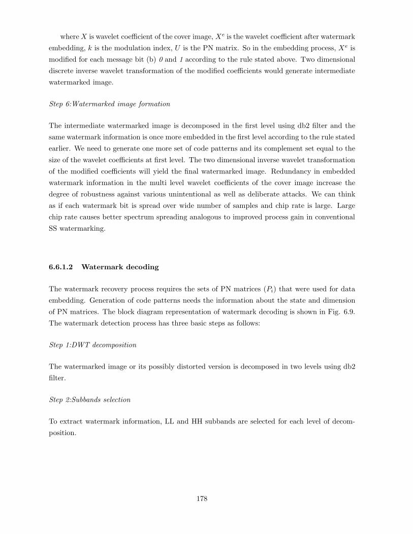
whereX is wavelet coefficient of the cover image, Xe is the wavelet coefficient after watermark
embedding, k is the modulation index, U is the PN matrix. So in the embedding process, Xe is
modified for each message bit (b) 0 and 1 according to the rule stated above. Two dimensional
discrete inverse wavelet transformation of the modified coefficients would generate intermediate
watermarked image.
Step 6:Watermarked image formation
The intermediate watermarked image is decomposed in the first level using db2 filter and the
same watermark information is once more embedded in the first level according to the rule stated
earlier. We need to generate one more set of code patterns and its complement set equal to the
size of the wavelet coefficients at first level. The two dimensional inverse wavelet transformation
of the modified coefficients will yield the final watermarked image. Redundancy in embedded
watermark information in the multi level wavelet coefficients of the cover image increase the
degree of robustness against various unintentional as well as deliberate attacks. We can think
as if each watermark bit is spread over wide number of samples and chip rate is large. Large
chip rate causes better spectrum spreading analogous to improved process gain in conventional
SS watermarking.
6.6.1.2 Watermark decoding
The watermark recovery process requires the sets of PN matrices (Pi) that were used for data
embedding. Generation of code patterns needs the information about the state and dimension
of PN matrices. The block diagram representation of watermark decoding is shown in Fig. 6.9.
The watermark detection process has three basic steps as follows:
Step 1:DWT decomposition
The watermarked image or its possibly distorted version is decomposed in two levels using db2
filter.
Step 2:Subbands selection
To extract watermark information, LL and HH subbands are selected for each level of decom-
position.
178

Figure 6.9: Block diagram of watermark decoding using DWT
Step 3:SS demodulation
To decode each watermark bit, two correlation values (one from LL and other from HH sub band)
are calculated in each scale. The correlation values are obtained by taking the inner product
of the LL subband with the respective code pattern (Pi) and HH subband with the respective
complemented code pattern (Pi). Mathematically this is accomplished by taking elementwise
multiplication and then summation. Thus, for each watermark bit, total Mw2 (total number
of watermark bits) number mean correlation values (µi) are obtained in each scale where i=
1, 2, ..Mw2. We apply antipodal signalling scheme for data embedding and these correlation
values can directly be used for bit detection considering ‘0’ as threshold. However, robustness
performance cannot be satisfactory as the correlation values are calculated by taking chip wise
integration. More stable and appropriate threshold can be calculated by taking integration over
larger duration and is described as follows.
An overall mean correlation value (T1) is calculated from these mean correlation values in
each scale where subscript ‘1’ indicates lower resolution scale (say). Thus we have two such
overall mean correlation values (T1) and (T2) (say, higher scale resolution) corresponding to two
different scale of resolutions. A resultant mean correlation value (T) can be calculated from
these two correlation and is used as the threshold for watermark decoding. The decision rule
for the decoded watermark bit is as follows:
if (i) µi ≥ T , the extracted bit is ’0’ and
if (ii) µi < T , the extracted bit is ’1’.
The threshold so obtained is more stable and improves reliability in watermark detection
leading to robustness against various possible signal distortions. This improved reliability is
179

very much essential against various possible signal distortions.
6.6.2 SS watermarking using BiDWT & interference cancellation[162]
BiDWT decomposition has shown better directional selectivity compared to conventional DWT
decomposition. The property of BiDWT decomposition can be exploited to design more robust
watermarking technique through host signal interference cancelation.
The main objective of the proposed technique is to improve payload. Biorthogonal wavelets
decompose the cover image in different directions and multiple watermark messages are then
embedded successively in the subbands. Successive interference cancelation (SIC) is used in the
proposed technique to improve robustness and embedding capacity.
6.6.2.1 Watermark embedding
The schematic of the proposed watermark embedding process is shown in Fig. 6.10. There
are four main modules in the embedding process: i) Discrete Wavelet Transform (DWT), ii)
Subband Selection, iii) Spread Spectrum Modulation, and iv) Inverse DWT. The basic steps of
watermark embedding are identical to the steps as discussed in algorithm 1. The difference lies
in the usage of DWT for signal decomposition. As the wavelet decomposition is not unique, a
large number of wavelet filters can be used. We use two biorthogonal wavelet filters (6,8) and
(4,4) for the cover signal decomposition in order to exploit HSI (host signal interference) which
is important to realize SS watermarking.
Figure 6.10: Block diagram of watermark embedding using BiDWT
180

6.6.2.2 Watermark decoding process
The watermark decoding algorithm is applied on a candidate image at the decoder to detect a
watermark. The schematic of the watermark decoding process is shown in Fig. 6.11. It is
observed that there are four major modules: (i) DWT, (ii) Subband Selection,(iii) SS
Demodulation and (iv) SIC. The functions of steps (i), (ii) and (iii) are same as described in
algorithm 1. We now briefly describe SIC method.
SIC technique
To improve embedding capacity at higher robustness, we use a successive interference
cancelation (SIC) scheme [271] where the decision statistics for an embedded bit is obtained by
subtracting an estimate of the already detected bits from the received signal. If estimation is
satisfactory, better detection is possible even for smaller modulation index values thus giving
rise to more information hiding for a given embedding distortion. The rationale behind such
argument lies due to faithful estimation of the bits and removal of their interference effect will
certainly improve detection reliability for the subsequent bits.
Figure 6.11: Block diagram of watermark decoding using BiDWT
6.6.3 QCM-SS watermarking[159]
We now discuss QCM based spread spectrum watermarking technique. Two binary watermark
images are embedded in respective subbands of two decompositions obtained using biorthogonal
wavelet based Hilbert transformation pairs. The novelty of the algorithm is that both the water-
marks are degraded in the similar fashion over a wide range of signal degradations. Watermark
embedding and decoding processes are exactly same as discussed in algorithm 1.
6.6.4 SS watermarking using M-band wavelets & N-ary modulation [163]
Watermark casting process may be divided in two steps: in first step a gray scale watermark im-
age is represented by less number of binary digits using novel channel coding and spatial biphase
181
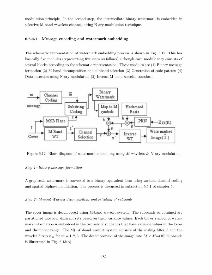
modulation principle. In the second step, the intermediate binary watermark is embedded in
selective M-band wavelets channels using N-ary modulation technique.
6.6.4.1 Message encoding and watermark embedding
The schematic representation of watermark embedding process is shown in Fig. 6.12. This has
basically five modules (representing five steps as follows) although each module may consists of
several blocks according to the schematic representation. These modules are (1) Binary message
formation (2) M-band decomposition and subband selection (3) Generation of code pattern (4)
Data insertion using N-ary modulation (5) Inverse M-band wavelet transform.
Figure 6.12: Block diagram of watermark embedding using M -wavelets & N -ary modulation
Step 1: Binary message formation
A gray scale watermark is converted to a binary equivalent form using variable channel coding
and spatial biphase modulation. The process is discussed in subsection 5.5.1 of chapter 5.
Step 2: M-band Wavelet decomposition and selection of subbands
The cover image is decomposed using M-band wavelet system. The subbands so obtained are
partitioned into four different sets based on their variance values. Each bit or symbol of water-
mark information is embedded in the two sets of subbands that have variance values in the lower
and the upper range. The M(=4)-band wavelet system consists of the scaling filter φ and the
wavelet filters ψm for m = 1, 2, 3. The decomposition of the image into M ×M=(16) subbands
is illustrated in Fig. 6.13(b).
182

Results obtained from the large number of images show that the variance values for the
coefficients of subbands H12, H13, H14 H24 are always in the lower range and for the sub bands
H41, H42, H43, H31, are in the upper range. The results are shown in bar diagrams of Fig.
6.13(a).
Figure 6.13: (a) Variance of different subbands; (b) Frequency bands corresponding to MbDWT
(M=4) band decomposition.
Step 3: Generation of code pattern
Rand function of standard Math library is used to generate spreading functions. Distinct code
patterns of N set with each set containing t number spreading functions are generated. We
denote the whole set by Pi where i = 1, 2, ..N . The value of N depends on the number of bits
required to represent a symbol and the value of ‘t′ equals to the total number of symbols that
the watermark contains depending on the choice of particular N -value. The length of the each
code C (spreading functions) is equal to the combined size of H12, H13, H14 H24 or H41, H42,
H43, H31. An identical M set code patterns denoted by Qi and orthogonal to the previous
sets are obtained by complementing bits of individual spreading functions of the set M . If any
code pattern of set Pi is used for data embedding in (H12, H13, H14 H24) channels (say channel
A), corresponding complemented code pattern of set Qi are used for data embedding in (H41,
H42, H43, H31) channels (say channel B). The use of complemented code patterns produces
183
low correlation with the corresponding image blocks (sub bands) and property (3) of the code
pattern is thus fulfilled. Each code of both the sets are modulated by one row of Hadamard
matrix and the modulated code patterns (l) are used for data embedding. It is quite simple
to understand that corresponding to each symbol in the watermark, there is one distinct code
pattern for all values of i of both Pi and Qi sets.
Step 4: Data insertion using N-ary modulation
Different symbols are assigned by the different i values in a well defined manner. The rule, for
example M = 8 (say), may be: symbols “000, 001, 010.....111” are assigned by the sets “i=1,
2....8” respectively. To embed a particular symbol, the code pattern to be added is determined
by the type of watermark symbol and its location in the watermark message. Say, if watermark
symbol at k-th position be 001, the code patterns of k-th position for the set i = 2 of Pi and Qi
will be added to the host signals of channels A and B respectively.
Step 5:Inverse M-band wavelet transform and Watermarked image formation
After embedding t number watermark symbols the inverse M band wavelet transform is done
to obtain the watermarked image.
6.6.4.2 Watermark dehiding and message decoding
The block diagram representation of watermark dehiding followed by message recovery processes
is shown in Fig. 6.14. There are four steps to be followed to accomplish this task. Steps are (1)
M-band wavelet decomposition and selection of subbands, (2)Watermark dehiding using N-ary
modulation, (3) Substring decoding, and Message decoding.
Step 1: M-band wavelet decomposition and selection of subbands
The watermarked image or its possibly distorted version is decomposed using M-band wavelets
and respective subbands are selected in which watermark information ere embedded.
Step 2: Watermark dehiding using N-ary demodulation
To decode a symbol at the particular position, correlation values are calculated between the
embedded wavelet channel and the spreading functions of the respective position for all the sets
Pi. The index of the largest correlation value i.e. the particular Pi whose respective spreading
function yields the maximum correlation value determines the decoded symbol.
According to the particular example mentioned in N -ary modulation if 1st modulation func-
tion of set P and Q yield the maximum correlation value with the selected set of subbands, the
184
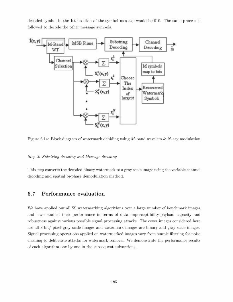
decoded symbol in the 1st position of the symbol message would be 010. The same process is
followed to decode the other message symbols.
Figure 6.14: Block diagram of watermark dehiding using M -band wavelets & N -ary modulation
Step 3: Substring decoding and Message decoding
This step converts the decoded binary watermark to a gray scale image using the variable channel
decoding and spatial bi-phase demodulation method.
6.7 Performance evaluation
We have applied our all SS watermarking algorithms over a large number of benchmark images
and have studied their performance in terms of data imperceptibility-payload capacity and
robustness against various possible signal processing attacks. The cover images considered here
are all 8-bit/ pixel gray scale images and watermark images are binary and gray scale images.
Signal processing operations applied on watermarked images vary from simple filtering for noise
cleaning to deliberate attacks for watermark removal. We demonstrate the performance results
of each algorithm one by one in the subsequent subsections.
185

6.7.1 Performance evaluation of DWT based SS watermarking
We have tested the performance of the algorithm against various possible signal processing
operations. Results are reported in two different cases namely by embedding (i) single watermark
and (ii) multiple watermarks inside the cover.
6.7.1.1 Robustness results for single watermark
Fig. 6.15(a) (Fishing Boat) shows a test cover image and Fig.6.15(c) shows the watermarked
image using logo/hidden symbol M of Fig. 6.15(b). We have calculated PSNR values for
large number of images and are averaged. The average PSNR between the watermarked image
and the original image is 36.09 dB with ε-value, i.e. security value of 0.020182. The values
become 38.73dB and 0.01786 when the code patterns used for watermarking are modulated by
Walsh/Hadamard kernel. The data imperceptibility measure and the security of the hidden
information for the test images are shown in Table 6.7. We use the notation PH/W when the
code pattern P is modulated by Walsh/Hadamard basis.
Figure 6.15: (a) Cover image, (b)Watermark image, (c)Watermarked image
Table 6.7: Imperceptibility and security of the hidden data for DWT based SS method
Test PSNR value (dB) PSNR value (dB) Security Security
Image using P usingPW/H ε-value ε-value
usingP usingPW/H
F. Boat 36.09 38.73 0.020182 0.01786
Lena 35.60 38.24 0.022214 0.016742
New York 36.12 38.13 0.021233 0.017523
Opera 35.81 37.93 0.133842 0.019521
Pill 36.34 37.76 0.042356 0.018567
186

Mean filtering
We test the resiliency of the scheme against mean filtering by applying a mask of size 3 × 3
for several times over the watermarked image. Fig. 6.16(a) shows the blurred version of the
watermarked image Fishing Boat obtained after applying 3 × 3 mask five times. The PSNR
value of the image corresponding to Fig. 6.16(a) is 21.9828 dB, whereas Fig. 6.16(b) shows
the extracted watermark symbol with good visual recognition. The mutual information value
I(X;Y ) for the extracted watermark is 0.068. The results of mean filtering for test images are
summarized in Table 6.8.
Median filtering
Fig. 6.16(c) shows the watermarked image Fishing Boat with PSNR value 24.64 dB obtained
after applying median filtering five times using spatial mask of size 3× 3. The extracted water-
mark with mutual information value I(X;Y )=0.085 is fully recognizable and is shown in Fig.
6.16(d). Results of the median filtering for the test images are shown in Table 6.8.
Figure 6.16: (a)Watermarked image after mean filtering (b)Extracted watermark form figure
(a);(c) Watermarked image after median filtering (d)Extracted watermark from figure (c)
It has been seen that the use of Walsh/Hadamard basis for modulating the code patterns
increases the resiliency performance of the scheme against both the types of filtering operations
for all test images.
Gaussian filtering
The watermarked image (PSNR=22.39 dB) after five times Gaussian filtering with variance 1
(window size 9×9) is shown in Fig. 6.17 (a). The extracted watermark image with I(X;Y )=0.11552
is shown in Fig.6.17 (b).
187

Table 6.8: Results of mean and median filtering for DWT based SS method
Test Stego Mean filtered Retrieved Median filtered Retrieved
Image image (dB) image (dB) logo with image (dB) logo with
(five times) I(X;Y ) (five times) I(X;Y )
F. Boat 38.73 21.98 Yes (0.068) 24.64 Yes (0.085)
Lena 38.24 23.21 Yes (0.06412) 27.32 Yes (0.0822)
New York 38.13 23.73 Yes (0.07023) 26.34 Yes (0.08224)
Opera 37.93 22.18 Yes (0.06712) 24.51 Yes (0.08123)
Pill 37.76 22.64 Yes (0.06324) 25.34 No (0.09134)
Figure 6.17: (a)Watermarked image after gaussian filtering (b)Extracted watermark from figure
(a); (c)Watermarked image after histogram equalization (d) Extracted watermark from figure
(c)
Histogram equalization
Fig. 6.17 (c) shows the watermarked image with PSNR value 17.21 dB obtained after his-
togram equalization operation. Fig. 6.17 (d) shows the extracted watermark image with mutual
information value I(X;Y )=0.21339.
Image sharpening
Fig. 6.18 (a) shows the watermarked image Fishing Boat after one such operation with PSNR
value 26.03 dB. The extracted watermark symbol is shown in Fig. 6.18 (b) with mutual infor-
mation value I(X;Y )=0.188.
188

Figure 6.18: (a) Watermarked image after image sharpening (b) Extracted watermark from
figure (b) (c) Watermarked image after noise addition (d) Extracted watermark from figure (c).
Table 6.9: Result of image sharpening and noise addition for five images
Test Stego Sharpened Retrieved Stego image Retrieved
Image image image (dB) logo after noise logo
(dB) I(X;Y ) addition (dB) I(X;Y )
F. Boat 38.73 26.03 Yes (0.18878) 35.70 Yes (0.19685)
Lena 38.24 25.32 Yes (0.17967) 34.23 Yes (0.18796)
New York 38.13 22.34 Yes (0.18967) 33.67 Yes (0.19568)
Opera 37.93 24.34 Yes (0.17734) 34.23 Yes (0.18426)
Pill 37.76 23.43 Yes (0.19134) 34.23 Yes (0.18750)
Figure 6.19: (a) Watermarked image after additive white gaussian noise (b)Extracted watermark
(c) Watermarked image after spackle noise; (d)Extracted watermark
Additive noise
We test robustness of the proposed scheme against random noise addition. The attack is sim-
ulated changing the gray value by 25%, for 25% randomly selected pixels of the watermarked
189
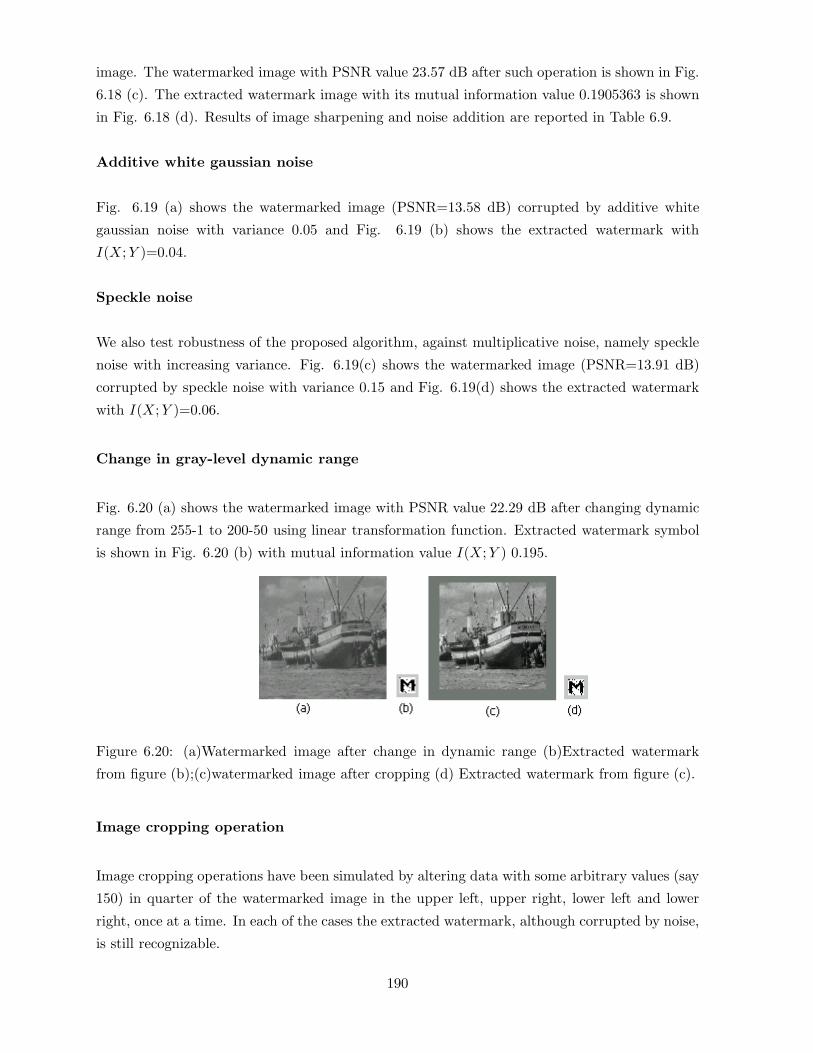
image. The watermarked image with PSNR value 23.57 dB after such operation is shown in Fig.
6.18 (c). The extracted watermark image with its mutual information value 0.1905363 is shown
in Fig. 6.18 (d). Results of image sharpening and noise addition are reported in Table 6.9.
Additive white gaussian noise
Fig. 6.19 (a) shows the watermarked image (PSNR=13.58 dB) corrupted by additive white
gaussian noise with variance 0.05 and Fig. 6.19 (b) shows the extracted watermark with
I(X;Y )=0.04.
Speckle noise
We also test robustness of the proposed algorithm, against multiplicative noise, namely speckle
noise with increasing variance. Fig. 6.19(c) shows the watermarked image (PSNR=13.91 dB)
corrupted by speckle noise with variance 0.15 and Fig. 6.19(d) shows the extracted watermark
with I(X;Y )=0.06.
Change in gray-level dynamic range
Fig. 6.20 (a) shows the watermarked image with PSNR value 22.29 dB after changing dynamic
range from 255-1 to 200-50 using linear transformation function. Extracted watermark symbol
is shown in Fig. 6.20 (b) with mutual information value I(X;Y ) 0.195.
Figure 6.20: (a)Watermarked image after change in dynamic range (b)Extracted watermark
from figure (b);(c)watermarked image after cropping (d) Extracted watermark from figure (c).
Image cropping operation
Image cropping operations have been simulated by altering data with some arbitrary values (say
150) in quarter of the watermarked image in the upper left, upper right, lower left and lower
right, once at a time. In each of the cases the extracted watermark, although corrupted by noise,
is still recognizable.
190
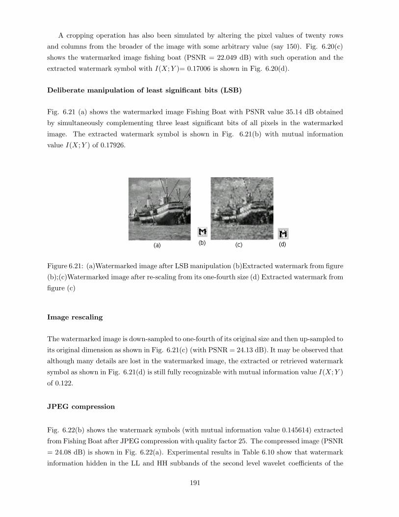
A cropping operation has also been simulated by altering the pixel values of twenty rows
and columns from the broader of the image with some arbitrary value (say 150). Fig. 6.20(c)
shows the watermarked image fishing boat (PSNR = 22.049 dB) with such operation and the
extracted watermark symbol with I(X;Y )= 0.17006 is shown in Fig. 6.20(d).
Deliberate manipulation of least significant bits (LSB)
Fig. 6.21 (a) shows the watermarked image Fishing Boat with PSNR value 35.14 dB obtained
by simultaneously complementing three least significant bits of all pixels in the watermarked
image. The extracted watermark symbol is shown in Fig. 6.21(b) with mutual information
value I(X;Y ) of 0.17926.
Figure 6.21: (a)Watermarked image after LSB manipulation (b)Extracted watermark from figure
(b);(c)Watermarked image after re-scaling from its one-fourth size (d) Extracted watermark from
figure (c)
Image rescaling
The watermarked image is down-sampled to one-fourth of its original size and then up-sampled to
its original dimension as shown in Fig. 6.21(c) (with PSNR = 24.13 dB). It may be observed that
although many details are lost in the watermarked image, the extracted or retrieved watermark
symbol as shown in Fig. 6.21(d) is still fully recognizable with mutual information value I(X;Y )
of 0.122.
JPEG compression
Fig. 6.22(b) shows the watermark symbols (with mutual information value 0.145614) extracted
from Fishing Boat after JPEG compression with quality factor 25. The compressed image (PSNR
= 24.08 dB) is shown in Fig. 6.22(a). Experimental results in Table 6.10 show that watermark
information hidden in the LL and HH subbands of the second level wavelet coefficients of the
191

Table 6.10: Results of JPEG compression for Fishing boat images when code patterns are and
are not modulated by Walsh/Hadamard basis
Quality PSNR(dB) for Retrieved PSNR(dB) for Retrieved
Factor Compressed image logo Compressed image logo
using P I(X;Y ) usingPW/H I(X;Y )
25 25.34 No(0.03298) 24.08 Yes (0.14561)
30 27.69 Yes(0.068573) 24.44 Yes (0.153591)
35 25.94 Yes(0.12187) 24.75 Yes (0.18567)
40 25.98 Yes(0.15252) 25.03 Yes (0.21058)
45 26.00 Yes(0.16782) 25.33 Yes (0.22658)
50 26.03 Yes(0.17798) 25.62 Yes (0.23065)
55 26.05 Yes(0.19109) 25.95 Yes (0.24337)
60 26.06 Yes(0.22109) 26.38 Yes (0.25354)
65 26.13 Yes(0.22514) 26.98 Yes (0.25428)
70 26.21 Yes(0.22514) 27.81 Yes (0.26450)
75 26.34 Yes(0.22937) 28.92 Yes (0.27786)
cover image offer better survivability of hidden data even after JPEG compression with high
compression ratio and low PSNR values i.e at low quality factors. Experimental results also show
that the use of Walsh/Hadamard basis for modulating the code patterns improve the robustness
against JPEG compression at low quality factor.
JPEG 2000 compression
Fig. 6.22(c) shows the watermarked image with PSNR value 22.31 dB obtained after JPEG
2000 compression at quality factor 25. The decoded watermark shown in Fig. 6.22(d) with
mutual information value I(X;Y )=0.097 is again fully recognizable. The resiliency performance
for Fishing boat image is shown in the Table 6.11 against JPEG 2000 compression at different
quality factor.
Collusion
The attack attempts to remove the original watermark by embedding several watermarks into
the same cover image. Five different watermarks were embedded separately into the cover image
Fishing boat and are then averaged. Fig. 6.23(a) shows an image obtained after such operation
using watermarks shown in Fig. 6.23(b) and Fig. 6.23(c) shows the extracted watermark images.
192

Figure 6.22: (a)Watermarked image after JPEG compression (quality factor 25); (b)Extracted
watermark from figure (b); (c)watermarked image after JPEG 2000 compression (quality factor
25); (d) Extracted watermark from figure(c)
Figure 6.23: Robustness results for collusion attacks (a) Stego image Fishing boat obtained after
averaging five stego images ; (b) Five watermark images; (c)Extracted watermark images
6.7.1.2 Robustness results for multiple watermark embedding
In this section we report the robustness results of multiple watermark embedding using (near)
orthogonal spreading codes. The objective of multiple access watermarking is to establish se-
cured transmission scheme of multiple messages through the same cover using (near) orthogonal
code patterns.
We embed three different binary watermark images of size (16×16) in the cover image Fish-
ing boat of size (256× 2566). Fig. 6.24(a) and 6.24(c) have shown the cover image Fishing boat
and the watermarked image when embedded by multiple watermarks as shown in Fig. 6.24(b).
Results of imperceptibility, security and robustness for other cover images are reported in Table
6.12.
193

Table 6.11: Results of JPEG 2000 compression for Fishing boat images when code patterns are
and are not modulated by Walsh/Hadamard basis
Quality PSNR(dB) for Retrieved PSNR(dB) for Retrieved
Factor Compressed image logo Compressed image logo
using P I(X;Y ) usingPW/H I(X;Y )
25 25.34 No(0.03298) 24.08 Yes (0.14561)
30 27.69 Yes(0.068573) 24.44 Yes (0.153591)
35 25.94 Yes(0.12187) 24.75 Yes (0.18567)
40 27.03 Yes(0.08507) 25.03 Yes (0.21058)
45 26.00 Yes(0.16782) 25.33 Yes (0.22658)
50 26.03 Yes(0.17798) 25.62 Yes (0.23065)
55 26.05 Yes(0.19109) 25.95 Yes (0.24337)
60 26.06 Yes(0.22109) 26.38 Yes (0.25354)
65 26.13 Yes(0.22514) 26.98 Yes (0.25428)
70 26.21 Yes(0.22514) 27.81 Yes (0.26450)
75 26.34 Yes(0.22937) 28.92 Yes (0.27786)
Mean filtering
Robustness results against mean filtering is reported in Table 6.13 and the watermarks are well
recognizable when extracted from the watermarked images after mean filtering using (5×5) mask.
Fig. 6.25(a) shows the watermarked image after mean filtering with the extracted watermarks
in Fig.6.25 (c).
Median filtering
Robustness results against median filtering is reported in Table 6.14 and the watermarks are well
recognizable when extracted from the watermarked images after median filtering using (5 × 5)
mask. Fig. 6.25(b) shows the watermarked image after median filtering along with the extracted
watermarks shown in Fig. 6.25(d).
Gaussian filtering
Watermarks are well recognizable when extracted from the watermarked images after two times
gaussian filtering with variance 1 (window size 9×9). Fig.6.26 (a) shows the watermarked image
after Gaussian filtering with the extracted watermarks shown in Fig. 6.26 (c).
194

Figure 6.24: (a) Cover image,(b)watermark images,(c)watermarked image
Table 6.12: Imperceptibility and security of multiple watermark embedding for DWT based SS
method
Test No of PSNR PSNR Security Security I(X;Y ) I(X;Y )
Image water- in(dB) in(dB) ε-value ε-value value value
marks using P usingPW/H usingP usingPW/H usingP usingPW/H
F. Boat 1 36.09 38.73 0.020692 0.01786 0.2217 0.2062
2 32.17 35.34 0.028765 0.021322 0.1995 0.1682
3 30.41 32.74 0.036757 0.0278546 0.2097 0.2001
Lena 1 35.60 38.24 0.007753 0.001786 0.2217 0.2062
2 31.67 34.84 0.018140 0.008786 0.1995 0.1682
3 29.91 32.25 0.029205 0.014243 0.2097 0.2001
Histogram Equalization
Fig. 6.26 (b) shows watermarked image after histogram equalization operation and Fig. 6.26
(d) shows the extracted watermark images.
Image Sharpening
Fig. 6.27 (a) shows watermarked image after image sharpening and extracted watermark images
is shown in Fig. 6.27 (c).
Change in dynamic range
Fig. 6.27 (b) shows the watermarked image after dynamic range change and the extracted
watermark images is shown in Fig. 6.27 (d).
195
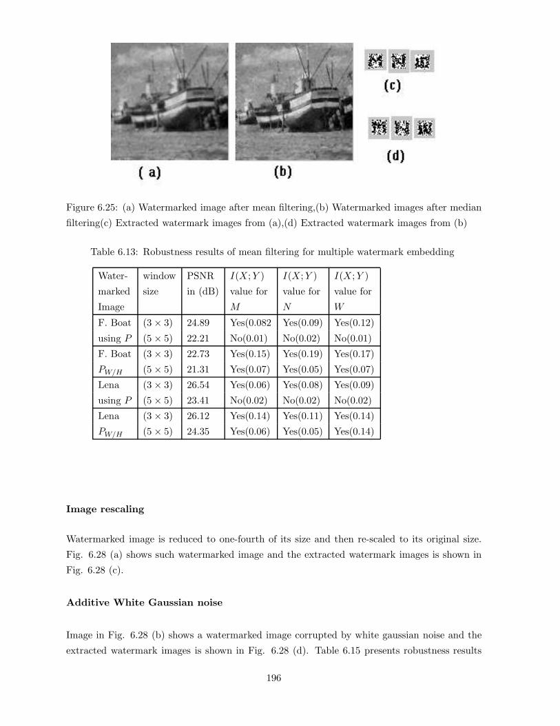
Figure 6.25: (a) Watermarked image after mean filtering,(b) Watermarked images after median
filtering(c) Extracted watermark images from (a),(d) Extracted watermark images from (b)
Table 6.13: Robustness results of mean filtering for multiple watermark embedding
Water- window PSNR I(X;Y ) I(X;Y ) I(X;Y )
marked size in (dB) value for value for value for
Image M N W
F. Boat (3 × 3) 24.89 Yes(0.082 Yes(0.09) Yes(0.12)
using P (5 × 5) 22.21 No(0.01) No(0.02) No(0.01)
F. Boat (3 × 3) 22.73 Yes(0.15) Yes(0.19) Yes(0.17)
PW/H (5 × 5) 21.31 Yes(0.07) Yes(0.05) Yes(0.07)
Lena (3 × 3) 26.54 Yes(0.06) Yes(0.08) Yes(0.09)
using P (5 × 5) 23.41 No(0.02) No(0.02) No(0.02)
Lena (3 × 3) 26.12 Yes(0.14) Yes(0.11) Yes(0.14)
PW/H (5 × 5) 24.35 Yes(0.06) Yes(0.05) Yes(0.14)
Image rescaling
Watermarked image is reduced to one-fourth of its size and then re-scaled to its original size.
Fig. 6.28 (a) shows such watermarked image and the extracted watermark images is shown in
Fig. 6.28 (c).
Additive White Gaussian noise
Image in Fig. 6.28 (b) shows a watermarked image corrupted by white gaussian noise and the
extracted watermark images is shown in Fig. 6.28 (d). Table 6.15 presents robustness results
196
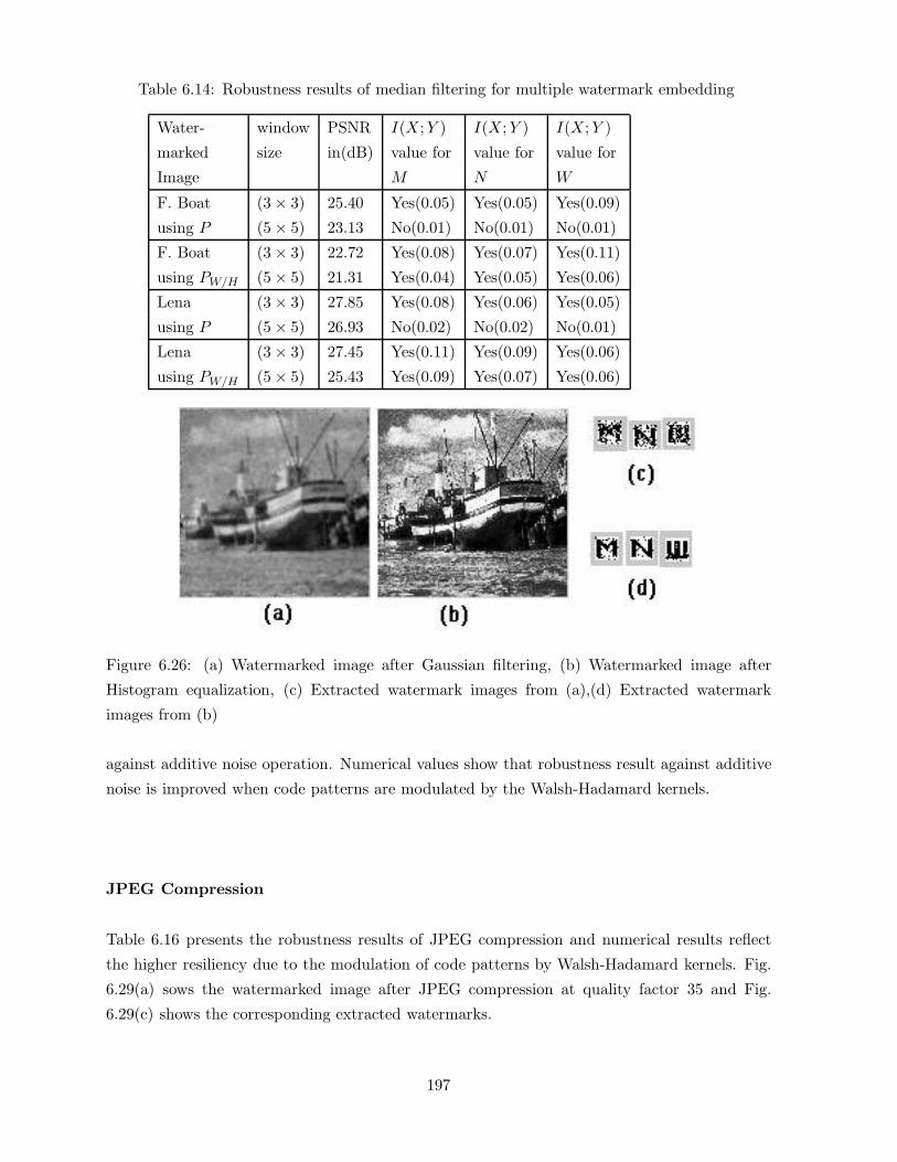
Table 6.14: Robustness results of median filtering for multiple watermark embedding
Water- window PSNR I(X;Y ) I(X;Y ) I(X;Y )
marked size in(dB) value for value for value for
Image M N W
F. Boat (3 × 3) 25.40 Yes(0.05) Yes(0.05) Yes(0.09)
using P (5 × 5) 23.13 No(0.01) No(0.01) No(0.01)
F. Boat (3 × 3) 22.72 Yes(0.08) Yes(0.07) Yes(0.11)
using PW/H (5 × 5) 21.31 Yes(0.04) Yes(0.05) Yes(0.06)
Lena (3 × 3) 27.85 Yes(0.08) Yes(0.06) Yes(0.05)
using P (5 × 5) 26.93 No(0.02) No(0.02) No(0.01)
Lena (3 × 3) 27.45 Yes(0.11) Yes(0.09) Yes(0.06)
using PW/H (5 × 5) 25.43 Yes(0.09) Yes(0.07) Yes(0.06)
Figure 6.26: (a) Watermarked image after Gaussian filtering, (b) Watermarked image after
Histogram equalization, (c) Extracted watermark images from (a),(d) Extracted watermark
images from (b)
against additive noise operation. Numerical values show that robustness result against additive
noise is improved when code patterns are modulated by the Walsh-Hadamard kernels.
JPEG Compression
Table 6.16 presents the robustness results of JPEG compression and numerical results reflect
the higher resiliency due to the modulation of code patterns by Walsh-Hadamard kernels. Fig.
6.29(a) sows the watermarked image after JPEG compression at quality factor 35 and Fig.
6.29(c) shows the corresponding extracted watermarks.
197

Table 6.15: Robustness results of additive white gaussian noise for multiple watermark embed-
ding
Water- Code variance PSNR I(X;Y ) I(X;Y ) I(X;Y )
marked pattern of in(dB) value for value for value for
Image noise M N W
F. Boat using P 0.03 14.68 Yes(0.07) Yes(0.09) Yes(0.09)
using PW/H 15.05 Yes(0.1) Yes(0.11) Yes(0.12)
Lena using P 0.03 15.54 Yes(0.08) Yes(0.09) Yes(0.09)
using PW/H 16.56 Yes(0.12) Yes(0.14) Yes(0.15)
Figure 6.27: (a) Watermarked image after image sharpening,(b)Watermarked image after dy-
namic range change, (c) Extracted watermarks from (a), (d) Extracted watermarks from (b)
JPEG 2000 Compression
Table 6.17 presents the robustness results of JPEG 2000 compression and numerical results
reflect the higher resiliency due to the modulation of code patterns by Walsh-Hadamard kernels.
Fig. 6.29 (b) sows the watermarked image after JPEG compression at quality factor 50 and Fig.
6.29 (d) shows the corresponding extracted watermarks.
198
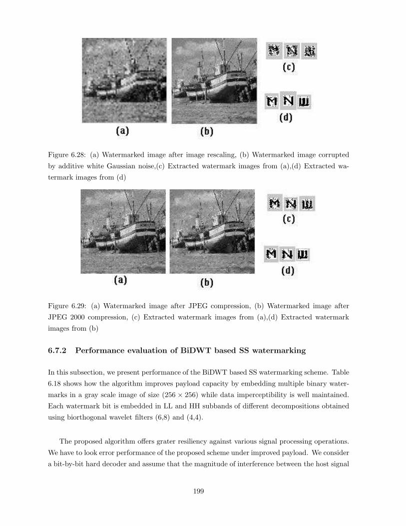
Figure 6.28: (a) Watermarked image after image rescaling, (b) Watermarked image corrupted
by additive white Gaussian noise,(c) Extracted watermark images from (a),(d) Extracted wa-
termark images from (d)
Figure 6.29: (a) Watermarked image after JPEG compression, (b) Watermarked image after
JPEG 2000 compression, (c) Extracted watermark images from (a),(d) Extracted watermark
images from (b)
6.7.2 Performance evaluation of BiDWT based SS watermarking
In this subsection, we present performance of the BiDWT based SS watermarking scheme. Table
6.18 shows how the algorithm improves payload capacity by embedding multiple binary water-
marks in a gray scale image of size (256 × 256) while data imperceptibility is well maintained.
Each watermark bit is embedded in LL and HH subbands of different decompositions obtained
using biorthogonal wavelet filters (6,8) and (4,4).
The proposed algorithm offers grater resiliency against various signal processing operations.
We have to look error performance of the proposed scheme under improved payload. We consider
a bit-by-bit hard decoder and assume that the magnitude of interference between the host signal
199

Table 6.16: Robustness results of JPEG compression in F. Boat image for multiple watermark
embedding
quality PSNR I(X;Y ) I(X;Y ) I(X;Y ) PSNR I(X;Y ) I(X;Y ) I(X;Y )
factor in(dB) value for value for value for using value value value
using P M N W PW/H M N W
35 27.12 No(0.01) No(0.01) No(0.01) 24.48 Yes(0.12) Yes(0.12) Yes(0.15)
40 27.43 No(0.01) No(0.01) No(0.01) 24.75 Yes(0.16) Yes(0.15) Yes(0.20)
45 28.64 No(0.01) No(0.01) No(0.01) 25.05 Yes(0.17) Yes(0.19) Yes(0.22)
50 28.35 No(0.02) No(0.01) No(0.02) 25.36 Yes(0.20) Yes(0.21) Yes(0.22)
55 29.12 Yes(0.05) Yes(0.04) Yes(0.04) 25.72 Yes(0.21) Yes(0.22) Yes(0.23)
60 29.49 Yes(0.06) Yes(0.05) Yes(0.05) 26.20 Yes(0.23) Yes(0.22) Yes(0.24)
65 29.93 Yes(0.07) Yes(0.04) Yes(0.05) 26.85 Yes(0.25) Yes(0.24) Yes(0.24)
70 30.47 Yes(0.08) Yes(0.06) Yes(0.07) 27.74 Yes(0.25) Yes(0.26) Yes(0.26)
75 31.10 Yes(0.08) Yes(0.10) Yes(0.12) 28.87 Yes(0.27) Yes(0.26) Yes(0.27)
and the code pattern is much smaller than the interference due to multiple bit embedding. Fig.
6.30 shows the conditional density function f(z/yk) of the detector statistics z along with the
region of error (shadded) for binary detection process. The bit error probability can be obtained
by integrating the overlapping Gaussian tails:
Pb =12[P (ε/Y 0) + P (ε/Y 1)] (6.71)
where ε indicates for the error. The probability function of the detector statistics, conditioned
on a symbol, is the sum of non-Gaussian random variables. If the number of terms is large
enough we may use central limit theorem and approximate the sum by a Gaussian distribution
with mean (µi) and variance (σ2i ) to be calculated from the expression of decision statistics. We
first write the expressions of watermarked image and decision statistics as follows:
Figure 6.30: Conditional pdf for binary decision and error regions
200

Table 6.17: Robustness results of JPEG 2000 compression in F. Boat image for multiple water-
mark embedding
quality PSNR I(X;Y ) I(X;Y ) I(X;Y ) PSNR I(X;Y ) I(X;Y ) I(X;Y )
factor in(dB) value for value for value for using value value value
using P M N W PW/H M N W
50 28.12 No(0.01) No(0.01) No(0.01) 23.30 Yes(0.18) Yes(0.19) Yes(0.20)
55 28.23 No(0.01) No(0.02) No(0.01) 23.73 Yes(0.18) Yes(0.21) Yes(0.20)
60 28.62 No(0.02) No(0.01) No(0.01) 24.02 Yes(0.19) Yes(0.20) Yes(0.21)
65 28.73 No(0.06) No(0.09) No(0.07) 24.23 Yes(0.19) Yes(0.21) Yes(0.22)
70 29.06 Yes(0.10) Yes(0.09) Yes(0.09) 24.62 Yes(0.21) Yes(0.22) Yes(0.23)
75 29.32 Yes(0.11) Yes(0.12) Yes(0.09) 24.87 Yes(0.23) Yes(0.24) Yes(0.22)
80 29.70 Yes(0.11) Yes(0.13) Yes(0.10) 25.20 Yes(0.24) Yes(0.22) Yes(0.22)
85 29.98 Yes(0.12) Yes(0.14) Yes(0.11) 25.43 Yes(0.24) Yes(0.23) Yes(0.22)
90 30.28 Yes(0.13) Yes(0.16) Yes(0.10) 25.67 Yes(0.25) Yes(0.24) Yes(0.24)
95 30.50 Yes(0.16) Yes(0.17) Yes(0.12) 25.98 Yes(0.26) Yes(0.24) Yes(0.27)
Table 6.18: Imperceptibility after embedding four (16 × 16) watermarks using (6, 8) and (4, 4)
BiDWT
Data imper- single two three four
ceptibility message messages messages messages
PSNR(dB) 35.502 35.501 34.731 34.354
MSSIM 0.9683 0.9681 0.9545 0.9543
X′l =
i=N∑i=1
i=L∑l=1
(Xl + α.Sil) (6.72)
Zk =< X′l , Skl >=
i=N∑i=1
i=L∑l=1
(Xl + α.Sil).Skl (6.73)
where Xl and X′l correspond to the wavelet coefficients of cover and the watermarked signals re-
spectively and Sil indicates the code patterns. The following equations, obtained from Equation
(6.73), represent the mean and the variance values of the decision variables respectively:
µi = T =1N
i=N∑i=1
Zi (6.74)
σ2i = V ar[Zk] = E[
i=N∑i=1
i=L∑l=1
(Xl + α.Sil).Skl]2
201
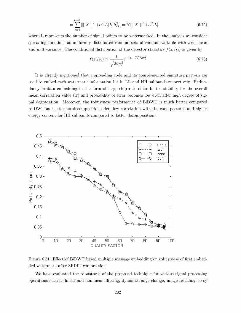
=i=N∑i=1
[‖ X ‖2 +α2.L]E[S2kl] = N [‖ X ‖2 +α2.L] (6.75)
where L represents the number of signal points to be watermarked. In the analysis we consider
spreading functions as uniformly distributed random sets of random variable with zero mean
and unit variance. The conditional distribution of the detector statistics f(zi/si) is given by
f(zi/si) � 1√2πσ2
i
e−(zi−Ti)/2σ2i (6.76)
It is already mentioned that a spreading code and its complemented signature pattern are
used to embed each watermark information bit in LL and HH subbands respectively. Redun-
dancy in data embedding in the form of large chip rate offers better stability for the overall
mean correlation value (T) and probability of error becomes low even after high degree of sig-
nal degradation. Moreover, the robustness performance of BiDWT is much better compared
to DWT as the former decomposition offers low correlation with the code patterns and higher
energy content for HH subbands compared to latter decomposition.
Figure 6.31: Effect of BiDWT based multiple message embedding on robustness of first embed-
ded watermark after SPIHT compression
We have evaluated the robustness of the proposed technique for various signal processing
operations such as linear and nonlinear filtering, dynamic range change, image rescaling, lossy
202
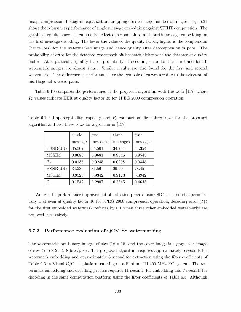
image compression, histogram equalization, cropping etc over large number of images. Fig. 6.31
shows the robustness performance of single message embedding against SPIHT compression. The
graphical results show the cumulative effect of second, third and fourth message embedding on
the first message decoding. The lower the value of the quality factor, higher is the compression
(hence loss) for the watermarked image and hence quality after decompression is poor. The
probability of error for the detected watermark bit becomes higher with the decrease of quality
factor. At a particular quality factor probability of decoding error for the third and fourth
watermark images are almost same. Similar results are also found for the first and second
watermarks. The difference in performance for the two pair of curves are due to the selection of
biorthogonal wavelet pairs.
Table 6.19 compares the performance of the proposed algorithm with the work [157] where
Pe values indicate BER at quality factor 35 for JPEG 2000 compression operation.
Table 6.19: Imperceptibility, capacity and Pe comparison; first three rows for the proposed
algorithm and last three rows for algorithm in [157]
single two three four
message messages messages messages
PSNR(dB) 35.502 35.501 34.731 34.354
MSSIM 0.9683 0.9681 0.9545 0.9543
Pe 0.0135 0.0245 0.0298 0.0345
PSNR(dB) 34.23 31.56 29.90 28.45
MSSIM 0.9523 0.9342 0.9123 0.8942
Pe 0.1542 0.2987 0.3545 0.4635
We test the performance improvement of detection process using SIC. It is found experimen-
tally that even at quality factor 10 for JPEG 2000 compression operation, decoding error (Pb)
for the first embedded watermark reduces by 0.1 when three other embedded watermarks are
removed successively.
6.7.3 Performance evaluation of QCM-SS watermarking
The watermarks are binary images of size (16 × 16) and the cover image is a gray-scale image
of size (256 × 256), 8 bits/pixel. The proposed algorithm requires approximately 5 seconds for
watermark embedding and approximately 3 second for extraction using the filter coefficients of
Table 6.6 in Visual C/C++ platform running on a Pentium III 400 MHz PC system. The wa-
termark embedding and decoding process requires 11 seconds for embedding and 7 seconds for
decoding in the same computation platform using the filter coefficients of Table 6.5. Although
203

the experiment has been performed over large number of cover images, however, Table 6.20
shows the effect of two message embedding on data imperceptibility for the few cover images.
Table 6.20: Data imperceptibility after embedding two different watermarks using QCM-SS
method
Test PSNR(dB) PSNR(dB) MSSIM MSSIM
images after single after two after single after two
message messages message messages
Lena 35.47 35.45 0.9536 0.9514
Boat 35.47 35.36 0.9623 0.9612
Pills 34.23 34.09 0.9454 0.9387
Opera 36.78 36.56 0.9645 0.9634
We have presented here the results corresponding to JPEG and JPEG 2000 compression
framework. Fig. 6.32 shows the robustness performance of two message embedding against
JPEG and JPEG 2000 compression operations. At a particular quality factor, probability of
decoding error for both the watermark images are almost same for a given compression frame-
work. This indicates that QCM watermarking scheme offers the same robustness performance
for the watermarks embedded in two decompositions. As expected, due to wavelet domain em-
bedding, robustness performance of the proposed algorithm against JPEG 2000 compression is
better compared to JPEG compression. This is indicated in Fig. 6.32 by low probability of error
values for the decoded watermarks in case of JPEG 2000.
Figure 6.32: Robustness performance against JPEG and JPEG 2000 compression operations for
the two watermarks embedded in two quadrature decompositions
204

Fig. 6.33 shows the robustness performance of the proposed algorithm against additive
gaussian noise. Robustness performance is decreased with the increase of the variance value of
the noise. As expected, QCM watermarking scheme, offers the similar performance variation for
both the decoded watermarks when watermarked images are corrupted by additive noise.
Figure 6.33: Robustness performance against additive gaussian noise operations for the two
watermarks embedded in two quadrature decompositions
205

6.7.4 Performance evaluation of M-band wavelets and N-ary modulation
We have presented here performance of spread spectrum watermarking technique developed
using M-band wavelets and N-ary modulation. The message signal is 4-bits/pixel gray-scale
image of size (64 × 64) and the cover image is a gray-scale image of size (256 × 2566), 8-
bits/pixel. The watermark image of size (32× 32) is obtained using spatial bi-phase modulation
by assigning a binary digit for a substring consisting of 64 symbols.
Figs. 6.34(a)-(e) show the test image, message signal, binary watermark, watermarked image,
and decoded message signal respectively. Figs. 6.34(b) and 6.34(e) show that the decoded
message is not identical to that of message signal. This indicates encoding loss due to channel
coding and biphase modulation. Table 6.21 presents probability of bit error, probability of
wrong decision in 4-th MSB (comparatively low due to higher redundancy) and 3-rd MSB of
the message signal. Numerical results also support the fact that smaller the length of the sub
string, the smaller is the message encoding loss but the size of the binary image becomes large.
The large binary message causes more embedding distortion for same robustness efficiency.
Table 6.21: Probability of error in single bit, 4-th bit and 3-rd bit during message encoding
Length of Prob. of Prob. of wrong Prob. of wrong
sub string bit error decision in decision in
p(e) 4th bit P (e1) 3rd bit P (e2)
4 0.107742 0.000663 0.009957
16 0.148758 0.002734 0.023853
64 0.219437 0.013599 0.064379
256 0.32301 0.053181 0.154462
Figure 6.34: (a) Original image,(b) Watermark image,(c) Binary watermark image, (d) Water-
marked image, (e) Decoded watermark image
206

Figure 6.35: Effect of (a) the use of Hadamard basis, hm indicates modulation by Hadamard
basis and (b) channel selection on detection reliability; (A) and (B) indicate channels A and B
respectively as described in the text.
The data imperceptibility measure and the security of the hidden information for the bench
marked images are shown in Table 6.22. The security value of the hidden data is measured using
Kulback-Leibler distance. Results in the table also show that the subbands (H12, H13, H14, H24)
(designated as channel A1) and (H41, H42, H43, H31) (designated as channel A2, A1 and A2
collectively called as channel A) offer better security and imperceptibility of the hidden data
compared to subbands (H44, H32, H33 H34) (Channel B1) and (H21, H22, H23, H11) (channel B2,
B1 and B2 collectively called as channel B). Table 6.23 shows how the structural index values
are varied with the modulation index values according to the variance of the image blocks.
Table 6.22: Imperceptibility and security of the hidden data using M -band wavelets & N -ary
modulation
Test MSSIM value MSSIM Security Security
Image in A channels in B channels ε-value ε-value
in A channel in B channel
Fishing Boat 0.9834 0.9645 0.012449 0.014611
Lena 0.9787 0.9569 0.003221 0.004059
New York 0.9794 0.9480 0.032035 0.041245
Opera 0.9845 0.9546 0.007398 0.008734
Pill 0.9786 0.9548 0.042356 0.064567
Fig. 6.35(a) shows that better robustness is achieved against lossy compression operations
when the code patterns are modulated by Hadamard basis compared to the direct use of code
patterns. Similarly Fig. 6.35(b) shows that the data embedding in channel A provides higher
resiliency compared to channel B when embedding distortion is held to an almost same value
207

Table 6.23: Effect of modulation index values on structural similarity measure
Modulation index (k1) Modulation index (k2) MSSIM
for low-variance for high-variance value
sub bands sub bands
0.3 0.3 (∼ 0.988)
0.3 0.7 (∼ 0.9459)
0.7 0.3 (∼ 0.976)
0.7 0.7 (∼ 0.934)
Figure 6.36: Effect of modulation functions on detection reliability; lines (1), (2) and (3) denote
the performance by using power law, linear and conventional modulation functions respectively
in both the cases. Channels A1 and A2 have low and high variance values respectively while
channels B1 and B2 have almost similar variance values. It is expected that for common signal
processing operations, channels B1 and B2 will be affected in the similar fashion while channels
A1 and A2 may be affected in different ways. So data embedding in the former pairs of channels
(subbands) may offer high robustness if the channels (subbands) are not affected much for the
particular types of attack or will show low robustness when they are affected much due to the
external attacks. Thus data embedding in these channels shows fading like performance for
various external attacks. On the other hand, channels A1 and A2 are being dissimilar in nature,
show better robustness against varieties of attacks assuming that at least one channel may show
good result for the particular attack.
Fig. 6.36 shows the performance of different modulation functions in achieving different
degree of robustness against JPEG and JPEG2000 operations. The graph shows that with the
increase in depth of compression linear modulation function shows better detection compared
to traditional SS watermarking scheme. This is quite clear from Equations (6.9) and (6.10)
208

where for a given attack distortion change in decision threshold ti in case of linear modulation
function is less compared to conventional modulation function. Under similar circumstance a
better detection is achieved if power-law function is used instead of linear modulation function.
This is due to the fact that with the decrease in numerical value of µ, the variance of the
embedded coefficients of the subbands is increased. The increased variance value is due to the
low correlation between the image blocks and code patterns (Equation (6.11)). Low correlation
value reduces the value of dti/dX for a given attack distortion.
The performance of M-ary modulation is shown in Fig. 6.37 where it is quite clear that with
the increase of M-value robustness efficiency is also improved. Although the result is reported
for JPEG and JPEG 2000 compression operation, but the result is also valid for other type of
signal processing operations.
Figure 6.37: Effect of M-ary modulation on detection reliability
We test robustness performance of the algorithm for different N and M values against
various possible signal processing operations. Fig. 6.38(a) and Fig. 6.38(b) show graphically
BER performance for N - values 2, 4, 8 and 16 with M -values 2 and 4 respectively under JPEG
2000 compression operations. In all cases, during embedding, α values i.e. embedding strength
are selected in such a way so that visual quality of the watermarked images remain to an almost
constant value. Results show that robustness performance for M = 3 and N = 4 is much better
209

than for M = 2 and N = 16 leading to low computation cost for decoding.
Figure 6.38: BER performance of different N-values for (a) M=2; (b) M=3 under JPEG 2000
compression
Figure 6.39: BER performance of different N-values for (a) M=4; (b) M=5 under JPEG 2000
compression
Fig. 6.39(a) and Fig. 6.39(b) show graphically results for M = 4 and M = 5. In all cases it
is found that significant improvement in robustness performance can be achieved at much lower
N-values by increasing M-values moderately.
Resiliency of the proposed algorithm has been tested against various signal processing op-
erations. Experimental results obtained from large number of images show that the decoded
message is quite visually recognizable even when there occurs 30% error in the extracted binary
watermark message. Table 6.24 summarizes the test results of different types of attacks using
210

Table 6.24: Test results of checkmark package for watermarking using M -band wavelets & N -ary
modulation
Name of I(X;Y) of the Decoded Name of I(X;Y) of the decoded
attack binary message attack binary message
watermark recognition watermark recognition
Wiener filtering 0.22345 yes dpr 0.20342 yes
dprcorr 0.20342 yes midpoint 0.17654 yes
threshold 0.24376 yes hard threshold 0.16795 yes
soft threshold 0.17245 yes sharpening 0.11532 yes
sampledown 0.15643 yes stirMark 0.09652 yes
templateremoval 0.17889 yes dither 0.16574 yes
trimeadmin 0.13643 yes copy-collage 0.132762 yes
projective 0.21452 yes ratio 0.19768 yes
rowcol 0.26571 yes shearing 0.098786 yes
warping 0.09245 yes rotation 0.04234 no
scaling 0.21342 yes
checkmark package.
211
6.8 Conclusions
In this chapter we have presented our studies on robustness improvement in SS watermarking
at high payload environment. We first point out few factors that are responsible for robustness
improvement in SS watermarking. The effect of some of these factors such as properties of the
code patterns, signaling scheme, determination of embedding strength, and choice of modula-
tion functions etc. on robustness improvement are than discussed mathematically. Robustness
performance is significantly improved if code patterns are distinct with zero average and have
minimum correlation among each other and also are uncorrelated with the cover. First two
properties of finite length code patterns are approximately met if the code patterns are modu-
lated by a row of Hadamard matrix of proper dimension. Apart from the properties of the code
patterns, signal adaptive SS watermarking offers better robustness compared to conventional SS
watermarking. It has been shown that for a given attack distortion, adaptive SS watermark-
ing using power law modulation function offers better resiliency compared to linear modulation
based SS method.
The effect of host signal interference is overcome in a better way (compared to unitary
transforms) by exploiting better scale-space tiling, multiresolution analysis, energy compactness
and directional decomposition offered by space-spatial frequency transformation. Two important
factors namely choice of signal decomposition tool and choice of subbands have significant impact
on robustness improvement in SS watermarking. While 2-band biorthogonal discrete wavelet
transform (BiDWT) offers benefit of detection reliability by reducing the effect of host signal
interference due to its better directional decomposition compared to DWT, M-band wavelets
offers advantages of better scale-space tiling, energy compactness and linear phase property
that helps in watermarking for selection of subbands, coefficients and reduction in computation
cost for signal decomposition. Mathematical analysis and experiment results show that data
embedding in LL and HH subbands (in case of 2-band systems) offer better spectrum spreading
and higher robustness. In the case of M-band wavelet system, two set of subbands with high and
low variance values are preferable for data embedding in order to cope up varieties of attacks.
Robustness performance are affected with the increase in payload capacity if embedding
distortion are held to an almost constant value. Popular multiplexing techniques namely code
division multiplexing, quadrature carrier multiplexing, multiuser detections namely successive
cancellation is used efficiently for improvement in detection reliability at high payload capacity.
BiDWT offers much benefits in this task. Payload capacity can be improved three to four times
with small signal degradation by embedding multiple watermarks in different decompositions
obtained by using different BiDWT.
Four different SS watermarking techniques using various wavelets and combination of factors
responsible for robustness improvement are proposed. In DWT based technique, robustness and
payload capacity are improved using signal adaptive modulation function and code division mul-
212

tiplexing respectively. For a given attack distortion, the use of linear modulation function offers
better robustness compared to conventional SS scheme while power law modulation function
improves this robustness performance better than linear function. Experiment results show that
the method is robust against various signal processing operations for both single watermark as
well as multiple watermarks. It is also shown that robustness performance is improved much
when code patterns are modulated by Walsh-Hadamard bases compared to the direct use of
code patterns.
BiDWT is used to design robust watermark design by exploiting directional decomposition
that yields low correlation with the spreading codes. The usage of multiple BiDWT allow
embedding of multiple watermarks leading to an increase in payload capacity. Biorthogonal
wavelets offer advantages to design Hilbert transform pair from. These advantages include
smoother filter coefficients of shorter length with symmetric property which reduces computation
cost significantly. Experimental results show that QCM based SS watermarking scheme improves
data embedding capacity two times with almost no change in image quality. Experimental results
show that both the watermarks are effected in similar fashion with the variation of a particular
signal degradation unlike BiDWT based multiple watermark embedding.
Higher robustness in SS watermarking is possible to achieve using M-band wavelets and
N-ary modulation principle. The variable channel coding and spatial biphase modulation con-
verts a grayscale watermark to binary equivalent form with less number of bits leading to an
improvement in payload capacity for a given embedding distortion. Data embedding in low
and high variance subbands of M -band decomposition offers better imperceptibility, faithful
decoding against varieties of attacks and security for the hidden data compared to embedding in
medium variance subbands that offers fading like detector performance. Exponential increase of
computation cost for decoding due to large N -values of N -ary modulation is trade-off by mod-
erate M -values in M -band wavelets which increase computation cost linearly. This trade-off
maintains robustness performance to a satisfactory level.
So far we have discussed different aspects of digital watermarking design from the point of
view of implementation domain, possible applications of various techniques like spread trans-
forms, spread spectrum in the system design and their experimental evaluation. In the next
(ultimate) chapter, the total overview of the contribution of this thesis in light of strength and
weakness of different proposed methodologies/techniques will be presented. This chapter will
also discuss the possibilities of extending the proposed methodologies for various other appli-
cation domains along with the possible remedial measures which may be developed to improve
performance of different techniques proposed in this thesis.
213

Chapter 7
Conclusions and Scope of Future
work
7.1 Conclusions and Discussions
The thesis has reviewed the existing methods and also has presented some new methodologies of
digital data hiding. The proposed watermarking methods may be used for tamper assessment,
authentication, copyright protection, and secret communication of data through images. To
achieve these goals, major attention has been put on the studies of issues like imperceptibility,
robustness and capacity while designing new data hiding algorithms. Majority of proposed
methodologies in this thesis have been designed from a viewpoint, where a digital watermarking
is considered as a digital communication problem. Accordingly, modulation and multiplexing
techniques have been used widely for designing efficient watermarking algorithms.
In chapter 3 and chapter 4, more attentions have been given on the imperceptibility aspect
of digital image watermarking. Some factors in image characteristics that are responsible for
imperceptibility are used for data embedding, e.g. in choosing the type of modulation and also
in the selection of modification process during embedding. It is shown that image characteristics
such as variance, average image information and average edge information of the pixel values
in a block, plays an important role in the selection of embedding regions considering imper-
ceptibility requirement. Simulation results show that the watermark information embedded in
the medium information bearing blocks can provide the best result for visual invisibility and
security. Imperceptibility is better achieved, if watermark image is modulated in such a manner,
that it well fits within the embedding region of the cover. But this requires a proper selection
of particular modulation form as well as corresponding controlling parameters, such that visual
distance between the watermarked and cover image is minimal. The selection process is complex
and it requires large time for computation. To minimize the computational time optimization
214

tool like GA is used.
Transform domain watermarking schemes decompose the cover signal in different ways.
Based on the nature of the particular kernels, it is possible to control the embedding strength
in such a manner that watermark remains imperceptible to the human sensory system. Ei-
ther additive or multiplicative scheme may be used for watermark embedding. Although the
additive method (non adaptive) is simpler to implement, but it is very sensitive to the choice
of embedding strength parameter which may vary with the cover content. A better control
on imperceptibility is possible in multiplicative embedding scheme. In this scheme, embedding
strength in each point varies according to the cover image coefficients. Various properties of the
HVS (human visual system), like frequency sensitivity, luminance masking and contrast mask-
ing play significant role in the calculation of the embedding strength while designing watermark
embedding rule. Experimental results show that the use of luminance, contrast and structure
information of the cover image ensures imperceptibility by minimum alteration of structural
features of the watermarked image.
In chapter 4, it is shown that how HVS (perceptual model) based approach can avoid the
selection of large smooth areas of a cover image for inserting strong watermark signal that often
causes the visual distortion after watermarking. Comparing the performance of the proposed
technique with that of other perceptual model based methods [83, 224], it is found that the
proposed technique offers better imperceptibility compared to the other two methods considering
the same level of robustness efficiency.
How to improve the robustness of a digital watermarking scheme, against valumetric distor-
tions is another major aim of study in the present thesis and is discussed in chapter 3. To achieve
this task, characteristics of image data, variable channel coding scheme, the concept of spread
transform and spread spectrum modulation are used. Variable channel coding principle is used
in LBM (low bit modulation) based spatial domain watermarking technique for embedding of
a gray scale watermark. Although its robustness is not of very high degree, but experimental
results show that variable channel coding based method can achieve relatively better resiliency
to signal processing operations compared to that based on simple channel coding. It is further
noted that image characteristics play an important role in the selection of embedding regions
to achieve better robustness, e.g. edge has been found to be an important site for robust wa-
termark design. In additive watermarking scheme using GA, it is found both experimentally
and analytically that linear function used to modulate the watermark offers better robustness
compared to parabolic and power law functions.
Transform domain methods perform better compare to spatial domain approach so far as
robustness against non-deliberate signal processing operations is concerned, which is verified
through experimental results in chapter 4. In order to design compression independent robust
watermarking, Discrete Hadamard Transform (DHT) is found to be good choice for decomposi-
215

tion of the cover. The method based on DHT shows better robustness performance compared to
that based on DCT and wavelets, when quality of compressed image is low both for JPEG and
JPEG 2000. A significant improvement in robustness can be achieved in spread transform tech-
nique with negative modulation. Experimental results also show that robustness performance
can further be improved, if watermark image is first spatially dispersed and then decomposed
before embedding it in image coefficients.
Studies are also been made on robustness performance, considering the embedder as an
attacker i.e. if multiple watermarks are embedded in the same cover image successively keeping
overall embedding distortion to a particular level. It is observed that the watermark which is
embedded first, always possesses high mutual information value. This automatically solves the
problem of finding out the rightful ownership. The watermarking algorithm proposed using HVS
is also found to be robust against majority of attacks available in checkmark package.
The chapter 6 puts major emphasis on further improvement of robustness in spread spectrum
watermarking, which is having inherent robustness characteristics through spectrum spreading
of watermark. It is shown mathematically that reliability in SS watermark decoding can be
improved, if the host signal interference and multiple bit interference effects generated due
to cross correlation among the code patterns are reduced properly. Robustness performance
is significantly improved if code patterns are distinct with zero average and have minimum
correlation among each other and also are uncorrelated with the cover. First two properties are
met approximately for a finite length code patterns if they are modulated by a row of Hadamard
matrix of proper dimension. Apart from the properties of the code patterns, signal adaptive SS
watermarking offers better robustness compared to conventional SS watermarking. It has been
shown that for a given attack distortion, adaptive SS watermarking using power law modulation
function offers better resiliency compared to linear modulation based SS method.
Space-spatial frequency transform reduces host signal interference in a better way compared
to unitary transform. This is due to the property of better directional decomposition and space-
frequency tiling. These phenomena are studied in details in the chapter 6. In 2- Band DWT
based SS method, data embedding in LL (low-low) and HH (high-high) sub bands offer better
spectrum spreading of the watermark compared to LH (low-high) and HL (high-low) sub bands
and thus results better robustness. Robustness performance of 2-band biorthogonal wavelets
(BiDWT) is better compared to 2-band DWT due to the better host signal interference reduction
property of the former. The performance is significantly improved in M-band decomposition,
as it offers advantages of better scale-space tiling and good energy compactness. Embedding of
each watermark bit in two sets of sub bands with low and high variances, shows better robustness
against varieties of attacks compared to the case when watermark is embedded in other two sets
of sub bands having close variances. It is also observed that if M band decomposition scheme with
higher M-values are used along with N-ary modulation, desired degree of robustness is achieved
at relatively low N- values. Thus a significant reduction in computation cost for decoding is
216

achieved compared to [137].
Capacity (for payload) is an important issue in many watermarking applications. It is re-
duced, if one tries to improve robustness for a given embedding distortion. Chapter 6 deals
with the issue of robustness improvement in SS watermarking under improved payload capacity.
It has been shown that code division multiplexing principle improves payload capacity with
marginal degradation in robustness performance and data imperceptibility. Better directional
selectivity of BiDWT improves payload capacity for a given robustness performance and embed-
ding distortions. In multiple bit SS watermarking, interference cancellation principle permits
low embedding strength, which in turn allows more information hiding for a given embedding
distortion and robustness improvement. Experimental results show that interference cancella-
tion improves robustness-capacity significantly compared to match filter detection. Quadrature
carrier multiplexing is an attractive method for doubling the payload capacity with almost no
deterioration in robustness performance and embedding distortion. Further improvement in
robustness is possible if QCM-SS watermarking is implemented using Hilbert transform pairs
designed from biorthogonal wavelet bases.
Low computation cost and ease of implementation are other two important requirements for
designing digital watermarking algorithms for real time application. Two LBM based spatial
watermarking schemes, which use channel coding principle, are computationally inexpensive and
easily implementable in hardware circuits. Chapter 3 discussed this issue in details. It has been
found that software implementation for the watermarking techniques proposed in chapter 4,
take less processing time when Discrete Hadamard transform (DHT) is used in place of DCT.
This is because of binary integer valued kernel of DHT, which reduces cost of computation
significantly. Binary valued symmetric kernel of DHT offers advantage of simpler hardware
realization and is shown in chapter 5. Biorthogonal wavelet bases used for designing Hilbert
transform pairs (described in chapter 6) generate smother and symmetric filter coefficients.
Reduction in computational cost to the extent of about one third of the original is possible if
shorter length and symmetric filter coefficients are used.
The digital watermarking algorithms developed in this thesis can be used for various appli-
cations. LBM based spatial watermarking algorithms find applications for authentication and
integrity verification of digital data in real time environment. GA based algorithms can be used
for hidden communication of data through innocuous looking image. Block based LBM methods
can be used for tamper detection while ST (spread transform) methods proposed in chapter 4
can be used for copyright protection of digital data due to its higher robustness performance.
The fragile SS watermarking method proposed in chapter 5 is mainly designed to serve the dual
purpose of authentication and QoS assessment of digital data, when transmitted through mobile
radio channel. The other SS watermarking method that embeds a gray scale watermark and its
circuit design makes it suitable to authenticate sender as well as secured communication of the
message. Robust SS watermarking methods with higher payload capacity proposed in chapter
217

6 may be used for copyright protection and hidden communication of data.
7.2 Scope of future work
The present thesis describes the development of few data hiding algorithms intended to achieve
improved performance of hiding process, such as content integrity, robustness and imperceptibil-
ity for image data. Algorithmic design spans over wide varieties of approaches and applications,
such as from simple spatial domain implementation to complex HVS based transform domain
approaches, fragile to robust high payload SS watermarking methods using discrete wavelets
and its variants. Due to the limited scope of the thesis, we could not able to address all the
problems related to the topics mentioned above with equal extent.
In chapter 4, optimization tool like GA is used for the proper selection of modulation form
and parameter for minimizing visual distance. In a similar way GA can fruitfully be used for
a problem where a large number of cover images and watermarks are available, and the task is
to find out the best suited watermark symbol for a particular cover. This may be implemented
using GA to find out the closest match between the spatial pixel pattern of watermark symbols
and the spatial pixel map of possible locations for hiding in the cover images. Such selection may
help the exiting methods to achieve superior degree of imperceptibility and robustness without
any further modifications.
In this thesis, we have restricted ourselves in the design of watermarking algorithms for gray
scale images only. At present, a large number of color images are used for various applications
and available on the web freely in the distributed archives. The content integrity and ownership
verification for this type of image is an important issue. Some of the algorithms proposed in this
thesis may be suitably modified to match the requirement for color image applications and may
be taken up as future scope for research. Measurement of QoS for video signal transmission is
also an important issue both for entertainments as well as mobile communication applications.
Method for blind assessment of QoS for signal through SS watermarking as discussed in chapter
5, may also be modified such that it can suit the purpose of video signal transmission.
The present thesis did not address the issue of robustness of the watermarking schemes
against certain types of geometric attacks like rotation, scaling and translation. These are very
important issues and may be taken up as a future scope of the present research work. Proposed
SS watermarking algorithms may be extended for the purpose using carrier interferometry (CI)
spreading codes [196] rather than using the binary valued code patterns. In the experimental
physics [254], interferometry refers to the study of interference patterns resulting from the su-
perpositioning of waves. The presence of distinct peaks and nulls in the interference patterns
has initiated the widespread use of interferometry. A set of code patterns called carrier in-
terferometry (CI) codes have been developed for application in CDMA communication. The
218

autocorrelation property of CI codes can be exploited to estimate certain degree of angular
rotation applied on the watermarked images.
SIC (Successive interference cancellation) is used to reduce interference effect in high pay-
load SS watermarking. In order to make decoding algorithm faster, PIC (parallel interference
cancelation) and its variant like block PIC may also be used. Multistage detection may also be
applied to reduce BER (bit error rate). Better performance may be achieved through the use
of Fuzzy logic based design in order to handle the uncertainty arising in interference estimation
at the initial stage of detection.
219

Bibliography
[1] In http://www.cl.cam.ac.uk/fapp2/watermarking.
[2] International workshop on digital watermarking. In http://www.iwdw.org/.
[3] International workshop on information hiding. In http://research.microsoft.com/ih2002/.
[4] Is&t/spie symposium on electronic image science and technology:security, steganography,
and watermarking of multimedia content. In http://electronicimaging.org/call/04/.
[5] Pacific rim workshop on digital steganography. In
http://www.know.comp.kyutech.ac.jp/STEG/.
[6] Secure digital music initiative (sdmi). In SDMI Portable Device Specification, Part 1, ver
1.0.
[7] Secure digital music initiative (sdmi). In http://www.sdmi.org.
[8] Special issue on copyright and privacy protection. IEEE Journal on Selected Areas in
Communication (JSCA), 16(4), May 1998.
[9] Special issue on watermarking. Communications of the ACM, 41(7), July 1998.
[10] Special issue on watermarking. Signal Processing, 66(3), May 1998.
[11] Special issues on copyright on emerging applications of multimedia data hiding. EURASIP
Journal on Applied Signal Proceedings (JASP), 2002(2), Feb. 2002.
[12] Special issue on signal processing for data hiding in digital media and secure content
delivery. IEEE Transaction on Signal Processing, 51(4), April 2003.
[13] Special issue on technologies for image security. Signal Processing:Image Communication,
18(4), April 2003.
[14] Special issue on enabling security technologies for digital rights management. Proceedings
of IEEE, 92(6), June 2004.
220

[15] Supplements on secure media. IEEE Transactions on Signal Processing, 52(10:Part 2),
October 2004.
[16] Supplements on secure media. IEEE Transactions on Signal Processing, 53(2:Part 2),
February 2005.
[17] Supplements on secure media. IEEE Transactions on Signal Processing, 53(10:Part 2),
October 2005.
[18] P. Abry and P. Flandrin. Multiresolution transient detection. In Proc. of IEEE Signal
Proc Int. Symp. Time-Frequency and Time-Scale Analysis, Philadelphia, pages 225–228,
1994.
[19] M. Acharya. On textured image analysis using wavelets. Ph. D thesis, Indian Statistical
Institute, Kolkata, India, 2002.
[20] N. Ahmed, T. Natarajan, and K. R. Rao. Discrete cosine transforms. IEEE Trans. Comp.,
C-23:90–93, 1974.
[21] A. M. Alattar. Smart image using digimarc’s watermarking technology. Proc. of Security
and Watermarking of Multimedia Contents II, SPIE, 3971:246–263, 2000.
[22] R. J. Anderson and F. A. P. Petitcolas. On the limits of steganography. IEEE Journal on
Selected Areas in Communication (JSCA), 16(4):474–481, May 1998.
[23] M. Antonini, M. Barlaud, P. Mathieu, and I. Daubechies. Image coding using the wavelet
transform. IEEE Trans. on Image Proc., 1:205–220, 1992.
[24] V. Argyriou, N. Nikolaidis, V. Solachidis, A. Tefas, A. Nikolaidis, S. Tsekeridou, and
I. Pitas. Optimark benchmark. http://poseidon.csd.auth.gr/optimark/, 2002.
[25] M. Arnold. Audio watermarking: features, applications and algorithms. In IEEE Int.
Conf. on Multimedia and Expo (ICME), Lausanne, Switzerland, volume 2, pages 1013–
1016, August 2000.
[26] M. Arnold and K. Schilz. Quality evaluation of watermarked audio tracks. SPIE Electronic
Imaging, 4675:91–101, 2002.
[27] M. Arnold, M. Schmucker, and S. D. Wolthusen. Techniques and Applications of Digital
Watermarking and Content Protection. World Scientific, Singapore, 2004.
[28] D. Artz. Digital steganography:hiding data within data. In IEEE Internet Computer,
volume 5.
[29] I. Avcibas, N. Memon, and B. Sankur. Steganalysis using image quality metrics. IEEE
Trans. on Image Processing, 12(2), February 2003.
221

[30] I. Avcibas, B. Sankur, and K. Sayood. Statistical analysis of image quality measures.
Journal of Electronic Imaging, 11:206–223, April 2002.
[31] P. P. Baidyanathan. Multirate systems and filter banks. Englewood Cliffs, NJ: Prentice
Hall, 1992.
[32] M. Barni and F. Bartolini. Watermark System Engineering. Marcel Dekker, New York,
USA, 2004.
[33] M. Barni, F. Bartolini, V. Cappellini, and A. Piva. A dct domain system for robust image
watermarking. Signal Processing, 66(3):357–372, May 1998.
[34] M. Barni, F. Bartolini, R. De, and A. Piva. Optimum decoding and detection of multi-
plicative watermarks. IEEE Trans. on Signal Processing, 51:1118–1123, 2003.
[35] M. Barni, F. Bartolini, and A. Piva. Improved wavelet-based watermarking through pixel-
wise masking. IEEE Trans. on Image Processing, 10(5):783–791, 2001.
[36] M. Barni, F.Bartolini, A. D. Rosa, and A. Piva. Capacity of the watermark channel:
how many bits can be hidden within a digital image ? Security and Watermarking of
Multimedia Contents, Proceedings of SPIE, 3657:437–448, 1999.
[37] M. Barni, C. I. Podilchuk, F. Bartolini, and E. J. Delp. Digital watermarking for copyright
protection: A communications perspective. IEEE Communications Magazine, pages 102–
108, August 2001.
[38] P. Bas, J. M. Chassery, and B. Macq. Image watermarking: an evolution to content based
approaches. Pattern Recognition), 35:545–561, 2002.
[39] P. Bassia, I . Pitas, and N. Nikolaidis. Robust audio watermarking in the time domain.
IEEE Transaction on Multimedia, 3:232–241, 2001.
[40] A. Bastug and B. Sankur. Improving the payload of watermarking channels via ldpc
coding. IEEE Signal Processing Letters, 11(2):90–92, 2004.
[41] S. Baudry, J. F. Delaigle, B. Sankur, and H. Maitre. Analysis of error correction strategies
for typical communication channel in watermarking. Signal Processing, 81(6):1239–1250,
June 2001.
[42] S. Baudry, P. Nguyen, and H. Maitre. Channel coding in watermark: use of soft decoding
to improve the watermark rettrieval. In Proc. IEEE Int. Conf. on Image Processing (ICIP),
volume 3.
[43] W. Bender and D. Gruhl. Techniques for data hiding. IBM Systems Journal, 35(4):314,
1996.
222

[44] W. Bender, D. Gruhl, N. Morimoto, and A. Lu. Techniques for data hiding. IBM System
Journal, 35(3-4):313–336, 1997.
[45] O. Benedens. Geometry-based watermarking of 3-d models. IEEE Computer Graphics
and Applications, pages 46–55, 1999.
[46] D. Benham, N. Memon, B. L. Yeo, and M. Yeung. Fast watermarking of dct-based com-
pressed images. In Proc. of the Int. Conf. on Imaging Science, Systems, and Technology,
Las Vegas, Nevada, volume 1, pages 243–252, 1997.
[47] H. Berghel and L. O. Gorman. Protecting ownership rights through digital watermarking.
volume 29, pages 101–103, 1996.
[48] A. K. Bhattacharya and H. Ancin. Data embedding in text for a copier system. In IEEE
Int. Conf. Image Processing (ICIP), October 1999.
[49] B. B. Bhattacharya, M. K. Kundu, S. P. Maity, C. A. Murthy, and T. Acharya. Robust
digital image watermarking utilizing a walsh transform algorithm. In US Patent application
field on 11th December 2003, application no. 20050144456.
[50] F.M. Boland, J.J. K O Ruanaidh, and C. Daurzenberg. Watermarking digital images for
copyright protection. In Proc. of the IEEE Int. Conf. on Imaging Proc. and its applications,
pages 321–326, 1995.
[51] D. Boneh and J. Shaw. Collusion-secure fingerprinting for digital data. IEEE Trans. on
Information Theory, 44:1897–1905, September 1999.
[52] A. G. Bors and I. Pitas. Image watermarking using dct domain constraints. In Proc. of
the IEEE Int. Conf. on Imaging Proc., volume 3, pages 231–234, 1996.
[53] G. W. Braudaway, K. A. Magerlein, and F. Mintzer. Protecting publicly available images
with a visible watermark. In Proc SPIE, Optical Security and Counterfeit Deterrence
Techniques, pages 106–111, August 1996.
[54] H. Brunk. Host-aware spread spectrum watermark embedding techniques. In Proc. SPIE
vol. 5020, Security andwatermarking of multimedia Contents V, January 2003.
[55] C. S. Burrus, R. A. Gopinath, and H. Guo. Introduction to wavelets and wavelet trans-
forms: a primer. Englewood Cliffs, NJ: Prentice Hall, 1997.
[56] C. Cachin. An information theoretic model for steganography. Proceedings of 2nd Work-
shop on Information Hiding, D. Aucsmith (Eds.),Lecture Notes in Computer Sciences,
Springer, 1525:306–318.
[57] J. P. Campbell. The human eye as an optical filter. Proceedings of the IEEE, 56:1009–1014,
June 1968.
223

[58] P. Campisi, M. Carli, G. Giunta, and A. Neri. Tracing watermarking for multimedia
communication quality assessment. In Proc. of IEEE Int. Conf. on Communication.
[59] P. Campisi, M. Carli, G. Giunta, and A. Neri. Blind quality assessment system for multime-
dia communications using tracing watermarks. IEEE Trans. on Signal Proc.,Special Issue
on Signal Proc. for Data hiding in Digital Media & Secure Content Delivery, 51(4):996–
1002, April 2003.
[60] P. Campisi, G. Giunta, and A. Neri. Object based quality of service assessment for mpeg-4
videos using tracing watermarking. In Proc. of IEEE Int. Conf. on Image Processing.
[61] C. K. Chan and L. M. Cheng. Improved hiding data in images by optimal moderately
significant-bit replacement. IEE Electron. Letter, 37(16):1017–1018, 2001.
[62] C. K. Chan and L. M. Cheng. Security of lin’s image watermarking system. The Journal
of Systems and Software, 62:211–215, 2002.
[63] C. K. Chan and L. M. Cheng. Hiding data in images by simple lsb substitution. Pattern
Recognition, 37:469–474, 2004.
[64] C. C. Chang and J. C. Chuang. An image intellectual protection scheme for gray-level
images using visual secret sharing strategy. Pattern Recognition Letters, 23:931–941, 2002.
[65] N. Checcacci, M. Barni, F. Bartolini, and S. Basagni. Robust video watermarking for
wireless multimedia communication. In Proc. of IEEE wireless multimedia communications
and networking Conference, volume 3, pages 1530–1535, 2000.
[66] B. Chen and G. W. Wornell. Achievable performance of digital watermarking systems. In
Proc. of IEEE Int. Conf. on Multimedia Computing and Systems (ICMS), volume 1.
[67] B. Chen and G. W. Wornell. Digital watermarking and information embedding using dither
modulation. In Proc. IEEE Workshop Multimedia Signal Processing, pages 273–278, 1998.
[68] B. Chen and G. W. Wornell. Provably robust digital watermarking. In Proc. SPIE
Multimedia System Application II, volume 3845, pages 43–54, September 1999.
[69] B. Chen and G. W. Wornell. Preprocessed and postprocessed quantization index modula-
tion ethods for digital watermarking. In Proc. SPIE :Security Watermarking Multimedia
Contents II, volume 3971, pages 48–59, January 2000.
[70] Q. Cheng and T. S. Huang. Robust optimum detection of transform domain multiplicative
watermarks. IEEE Transaction on Signal Processing, 51(4):906–924, April 2003.
[71] S. C. Cheung and D. K. W. Chiu. A watertermarking infrastructure for enterprise docu-
ment management. In 36th Annual Hawaii Int. Conf. on System Sciences, pages 105–114.
224

[72] J. Chou, S. S. Pradhan, L. E. Ghaoui, and K. Ramchandran. Watermarking based on
duality with distributed source coding and robust oprimization principles. In Proc. of
IEEE Int. Conf. on Image Proc. (ICIP), September 2000.
[73] P. R. Cook. Music, Cognition, and Computerized Sound: An Introduction to Psychoa-
coustics. The MIT Press, 1999.
[74] G. R. Cooper and C. D. McGillem. Modern communications and spread spectrum.
McGraw-Hill International Edition, New York, 1986.
[75] M. Corvi and G. Nicchiotti. Wavelet-based image watermarking for copyright protection.
In Scandinavian Conf. on Image Analysis SCIA, Finland, June 1997.
[76] T. M. Cover and J. A. Thomas. Elements of Information Theory. John-Wiley and Sons,
1991.
[77] I. J. Cox. Spread spectrum watermark for embedded signaling. In U. S. Patent, volume
5, 848, 155, December 1998.
[78] I. J. Cox, J. Kilian, T. Leighton, and T. Shamoon. Secure spread spectrum watermarking
for multimedia. In Technical Report, 95-10, NEC Research Institute, Princeton, NJ, USA,
1995.
[79] I. J. Cox, J. Kilian, T. Leighton, and T. Shamoon. A secure, robust watermark for mul-
timedia. In Proc. in first Int. workshop on Information hiding, R. Anderson, ed., Lecture
Notes in Computer Science, Springer Verlag, volume 1174, pages 185–206, May/June
1996.
[80] I. J. Cox, J. Kilian, T. Leighton, and T. G. Shamoon. Secure spread spectrum water-
marking for multimeida. In Proc. of IEEE Int. Conf. Image Processing (ICIP), October
1997.
[81] I. J. Cox, M. L. Miller, and J. A. Bloom. Digital Watermarking. Morgan Kaufmann, San
Francisco, 2001.
[82] I. J. Cox, M. L. Miller, and A. L. McKellips. Watermarking as communications with
side information. In Proc. of IEEE, Special Issues on Identification and Protection of
Multimedia Information, volume 87.
[83] I.J. Cox, J. Kilian, F. T. Leighton, and T. Shamoon. Secure spread spectrum watermarking
for multimedia. IEEE Trans. Image Processing, 6(12):1673–1687, December 1997.
[84] S. Daly. The visible difference predictor:an algorithm for the assessment of image fidelity.
Digital images and human vision: A. B. Watson Ed., MIT Press, pages 179–205, 1993.
225

[85] S. Decker. Engineering considerations in commercial watermarking. IEEE Communica-
tions Magazine, 2001.
[86] G. Depovere, T. Kalker, and J. P. Linnartz. Improved watermark detection reliability
using filtering before correlation. In Proc. of IEEE Int. Conference on Image Processing
(ICIP), volume 1, pages 430–434, 1998.
[87] J. Dittman and A. Steinmetz. Content-based digital signatures for motion pictures au-
thentication and content-fragile watermarking. In Proc. IEEE ICMCS, Florence, Italy,
pages 574–579, June 1999.
[88] J. Dittmann, P. Schmitt, E. Saar, J. Scwenk, and J. Ueberberg. Combining digital wa-
termarks and collusion secure fingerprints for digital images. SPIE Journal of Electronic
Imaging, 9:456–467, 2000.
[89] R. C. Dixon. Spread Spectrum Systems. John Wiley and Sons, New York, 1976.
[90] M. P. Eckert and A. P. Bradley. Perceptual quality metrices applied to still image com-
pression. Signal Processing, 70:177–200, November 1998.
[91] J. Eggers and B. Girod. Informed Watermarking. Kluwer Academic Publishers, USA,
2002.
[92] J. J. Eggers, R. Bauml, and B. Girod. Digital watermarking facing attacks by amplitude
scaling and additive white noise. In 4th Int. ITG Conference on Souencerce and Channel
Coding.
[93] A. M . Eskicioglu. Application of multidimensional quality measures to reconstructed
medical images. Optical Engineering, 35:778–785, March 1996.
[94] A. M . Eskicioglu and P. S. Fisher. Image quality measurement and their performance.
IEEE Trans. on Communication, 43:2959–2965, December 1995.
[95] C. Fei, D. Kundur, and R. H. Kwong. Analysis and design of watermarking algorithm
for improved resistance to compression. IEEE Trans. on Image Proc., 13(2):126–144,
February 2004.
[96] J. D. Ferrer and F. Sebe. Invertible spread-spectrum watermarking for image authentica-
tion and multilevel access to precision-critical watermarked images. In Proc. of the Int.
Conference on Information Technology Coding and Computing (ITCC’02), 2002.
[97] J. Fridrich. Image watermarking for tamper detection. In Proc. of IEEE Int. Conf. of
Image Processing (ICIP), pages 404–408, October 1998.
[98] J. Fridrich and M. Goljan. Protection of digital images using self embedding. In Proc. of
Symposium on Content Security and Data Hiding in Digital Media, May 1999.
226

[99] J. Fridrich, M. Goljan, and C. Baldoza A. New fragile authentication watermark for images.
In Proc. of IEEE Int. Conf. of Image Processing (ICIP), pages 446–449, September 2000.
[100] A. Garimella, M. V. V. Satyanarayana, R. S. Kumar, P. S. Murugesh, and U .C. Niranjan.
Vlsi implementation of online digital watermarking technique with difference encoding for
8-bit gray scale images. In 16th Int. Conf. VLSI Design.
[101] B. Girod. What’s wrong with mean-squared error. In Digital Images and Human Vision,
A. B. Watson, ED., the MIT Press.
[102] D. E. Goldberg. Genetic Algorithms in Search, Optimization, and Machine Learning.
Adison-Wesley,Reading, MA, 1989.
[103] R. C. Gonzalez and R. E. Woods. Digital Image Processing. Pearson Education, Singapore,
2002.
[104] R. Grobois and T. Ebrahimi. Watermarking in jpeg 2000 domain. In Proc. of the IEEE
workshop on multimedia signal proc., pages 3–5, 2001.
[105] C. E. Halford, K. A. Krapels, R. G. Driggers, and E. E. Burroughs. Developing operational
performance metrics using image compression metrics and the concept of degradation
space. Optical Engineering, 38:836–844, May 1999.
[106] L. Hanzo, P.J. Cherriman, and J. Streit. Wireless video communication: Second to third
generation systems and beyond. In IEEE series on digital and mobile communication,
New York, 2001.
[107] F. Hartung and M. Kutter. Multimedia watermarking techniques. Proceedings of IEEE,
87(7):1079–1107, July 1999.
[108] F. Hartung, J. K. Su, and B. Girod. Spread spectrum watermarking: malicious attacks
and counterattacks. In Proc. of SPIE, Security and watermarking of multimedia contents,
volume 3657, pages 147–158, January 1999.
[109] S. Haykin. Communication Systems, 3/e. John Wiley and Sons, Singapore, 1996.
[110] J. Hernandez, F. Perez-Gonzalez, and J. Rodriguez. The impact of channel coding on the
performance of spatial watermarking for copyrights protection. In Proc. IEEE ICASSP,
volume 5, pages 2973–2976, 1998.
[111] Herodotous. The Histories. J. M. Dent and Sons Ltd., London, England, 1992.
[112] A. T. S. Ho, J. Shen, A. K. K. Chow, and J. Woon. Robust digital image-in-image water-
marking algorithm using the fast hadamard transform. In IEEE International Symposium
on Circuits and Systems, 2003.
227

[113] J. H. Holland. Adaptation in natural and artificial systems. University of Michigan
Press,Ann Arbor, 1975.
[114] M. Holliman, N. Memon, B. L. Yeo, and M. Yeung. Adaptive public watermarking of
dct-based compressed images. In Proc. of the SPIE Int. Conf. on Storage and Retrieval
for Image and Video Databases VI, San Jose, CA, volume 3312, pages 284–295, 1998.
[115] J. K. Holmes. Coherent spread spectrum systems. Wiley-Interscience, New York, 1982.
[116] Y.C. Hou and P. M. Chen. An assymetric watermarking scheme based on visual cryptog-
raphy. In Proc. of IEEE fifth ICSP, pages 992–995, 2000.
[117] C. T. Hsu and J. L. Wu. Hidden signatures in images. In Proc. of the IEEE Int. Conf. on
Imaging Proc., pages 743–746, 1996.
[118] C. T. Hsu and J. L. Wu. Multiresolution watermarking for digital images. IEEE Trans.
CASII: Analog and Digital signal processing, 45:1097–1101, February 1998.
[119] C. T. Hsu and J. L. Wu. Hidden digital watermark in images. IEEE Trans. Image
Processing, 8:58–68, 1999.
[120] L. Hua and J. E. Fowler. A performance analysis of spread-spectrum watermarking based
on redundant transforms. In Proc. of the IEEE Int. Conference on Multimedia and Expo,
volume 2, pages 553–556, 2002.
[121] J. Huang, Y. Q. Shi, and Y. Shi. Embedding watermarks in dc components. IEEE
Transaction on Circuits, Systems for Video Technology, 10(6):974–979, June 2000.
[122] M. S. Hwang, C. C. Chang, and K. F. Hwang. Digital watermarking of images using neural
networks. Journal of Electronic Imaging, 9:548–555, 2000.
[123] R. W. Hwang. A robust algorithm for information hiding in digital pictures. In M.E.
thesis in Electrical and Computer Engineering, MIT Media Laboratory, 1999.
[124] A. K. Jain. Fundamentals of digital image processing. Prentice Hall, Singapore, 1989.
[125] I. M. Jimenez and A. N. Vazquez. A new spread spectrum watermarking method with
self-synchronization capabilities. In Proc. of IEEE Int. Conference on Image Processing
(ICIP), volume 1, pages 415–418, 2000.
[126] K. A. D. Jong. On using genetic alg.
[127] D. Kahn. The Codebreakers-The story of Secret Writing. New York, USA, 1996.
[128] T. Kalker and J. Haitsma. Efficient detection of a spatial spread-spectrum watermarking
in mpeg video streams. In Proc. IEEE Int. Conf. Image Processing (ICIP), pages 434–437,
October.
228

[129] S. Katzenbeisser and F. A. P. Petitcolas. Information Hiding Techniques for Steganography
and Digital Watermarking. Artech House, Boston, London, 2000.
[130] M. Kobayashi. Digital watermarking: Historical roots. In Technical Report RT0199, IBM
Research, Tokyo Research Laboratories, Japan, 1997.
[131] E. Koch and J. Zhao. Towards robust and hidden image copyright labeling. In Proc. IEEE
Int. Workshop on Nonlinear Signal and Image Processing.
[132] T. Kohda, Y. Ookubo, and K. Shinokura. Digital watermarking through cdma channels
using spread spectrum techniques. In Proc. of IEEE Int. Symposium on Spread Spectrum
Techniques and Applications, volume 2, pages 671–674, September 2000.
[133] H. P. Kramer and M. V. Mathews. A linear coding for transmitting a set of correlated
signals. IRE Trans. Info. Theory, IT-2:41–46, 1956.
[134] D. Kundur and D. Hatzinakos. A robust digital image watermarking method using wavelet-
based fusion. In Proc. of the IEEE Int. Conf. on Imaging Proc., volume 1, pages 544–547,
1997.
[135] D. Kundur and D. Hatzinakos. Digital watermarking for telltale tamper-proofing and
authentication. Proceedings of the IEEE, Special Issue on Identification Protection of
Multimedia Infoermation, 87(7):1167–1180, July 1999.
[136] D. Kundur and D. Hatzinakos. Diversity and attacks characterisation for improved robust
watermarking. IEEE Trans. on Signal Processing, 29(10):2383–2396, October 2001.
[137] M. Kutter. Performance improvement of spread spectrum based image watermarking
schemes through m-ary modulation. In Proceedings of the Workshop on Information Hid-
ing, LNCS-1768,Springer Verlag, New York, pages 238–250, 1999.
[138] J. Lacy, S. Quackenbush, A. Reibman, and J. Snyder. Intellectual property protection and
digital watermarking. Information Hiding Workshop, D. Aucsmith, Ed. Springer-Verlag,
1525:158–168, 2000.
[139] B. Lambrecht. Special issues on image and video quality metrics. Signal Processing, 70,
October 1998.
[140] G. C. Langelaar, I. Setyawan, and R. L. Lagendijk. Watermarking digital image and video
data: A state-of-the-art overview. IEEE Signal Processing Magazine, 17:20–46, 2000.
[141] A. Levy and N. Merhav. An image watermarking scheme based on information theoretic
principles. In HPL Invention Disclosure, 2000.
[142] F. Yong Li, N. Stol, T. T. Pham, and S. Andresen. A priority-oriented qos management
framework for multimedia services in umts. In Proc. Fourth Int. IEEE Symp. Wireless
Pers. Multimedia Commun., Aalborg, Denmark, pages 9–12, September 2001.
229
[143] C. Y. Lin. Watermarking and digital signature techniques for multimedia authentication
and copyright protection. In Ph. D Dissertation,Columbia University, 2000.
[144] A. Lumini and D. Maion. A wavelet based image watermarking scheme. In Proc. IEEE
Int. Conf. on Information Technology: Coding and Computing, pages 122–127, 2000.
[145] B. Macq and J. J. Quisquater. Digital images multiresolution encryption. Journal Inter-
active Multimedia Assoc. Intellect. Property Project, 1:187–206, January 1994.
[146] F. J. Macwilliams and N. J. A. Sloane. The theory of error-correcting codes.
Amsterdam,North-Holland, 1996.
[147] S. P. Maity, A. Banerjee, A. Abhijit, and M. K. Kundu. Vlsi design of spread spectrum
watermarking. In Proc. 13th National Conf. on Communication (NCC-2007), IIT Kanpur,
India, pages 251–257, January 2007.
[148] S. P. Maity, A. Banerjee, and M. K. Kundu. An image-in-image communication scheme
and vlsi implementation using fpga. In IEEE Indian Annual Conf. (INDICON 2004), IIT
Kharagpur, India, pages 6–11, December 2004.
[149] S. P. Maity and M. K. Kundu. Digital image watermarking scheme using visual model
and spread transform. Signal Processing, Elsevier, communicated.
[150] S. P. Maity and M. K. Kundu. Digital watermarking using image information. Interna-
tional Journal of Information Technology, Singapore Computer Society, communicated.
[151] S. P. Maity and M. K. Kundu. Structure retention in digital image watermarking. Com-
puters and Electrical Engineering, Elsevier, communicated.
[152] S. P. Maity and M. K. Kundu. Digital watermarking: A technique for secure transmis-
sion. In Proc. of Int. Conf. on Control, Instrumentation and Information Communication
(CIIC-2001), pages 527–531, December 2001.
[153] S. P. Maity and M. K. Kundu. Information theoretic approach to spatial image wa-
termarking. In Proc. of Int. Conf. on Computer Vision, Graphics with special session
for young scientists and summer school on image processing (ICCVG-2002), Zakopane,
Poland, pages 524–529, September 2002.
[154] S. P. Maity and M. K. Kundu. Robust and blind spatial watermarking in digital image. In
Proc.of third Indian Conf. on Computer Vision, Graphics and Imag Processing (ICVGIP-
02), Ahmedabad, India, pages 388–393, December 2002.
[155] S. P. Maity and M. K. Kundu. A blind cdma image watermarking scheme in wavelet
domain. In IEEE Int. Conf. on Image Processing (ICIP-2004), pages 2633–2636, 2004.
230
[156] S. P. Maity and M. K. Kundu. An image watermarking scheme using hvs characteristics
and spread transform. In Proc. of 17th Int. Conf. on Pattern Recognition (ICPR 2004),
Cambridge, UK, IEEE CS Press, volume 4, pages 869–872, 2004.
[157] S. P. Maity, M. K. Kundu, and T. S. Das. Design of a robust spread spectrum image
watermarking scheme. In 4th Indian Conf. on Computer Vision, Graphics and Image
Processing (ICVGIP-04), Kolkata, India, volume 2, pages 140–145, 2004.
[158] S. P. Maity, M. K. Kundu, and T. S. Das. Robust ss watermarking with improved ca-
pacity. Special Issues in Pattern Recognition Letters (Advances in Visual Information
Processing),Elsevier Science, 28:350–356, February 2007.
[159] S. P. Maity, M. K. Kundu, and S. Maity. Capacity improvement in digital watermarking
using qcm scheme. In Proc. 12th National Conf. on Communication (NCC-2006), IIT
Delhi, India, pages 511–515, 2006.
[160] S. P. Maity, M. K. Kundu, and S. Maity. An efficient digital watermarking scheme for
dynamic estimation of wireless channel condition. In Int. Conf. on Computing: Theory and
Applications, IEEE CS Press. Indian Statistical Institute, Kolkata, India, pages 671–675,
March 2007.
[161] S. P. Maity, M. K. Kundu, and Seba Maity. Dual purpose spread spectrum image
watermarking in real-time. Special issues: circuits & systems for realtime security &
copyright protection of multimedia, International Journal of of Computers & Electrical
Engg.,Elsevier, communicated.
[162] S. P. Maity, M. K. Kundu, and M. K. Mandal. Capacity improvement in spread spectrum
watermarking using biorthogonal wavelets. In IEEE Int.Midwest Symposium on Circuits
and Systems (IEEE MWSCAS 2005), Cincinnati, Ohio, 2005.
[163] S. P. Maity, M. K. Kundu, and M. K. Mandal. Performance improvement in spread
spectrum watermarking via m-band wavelets and n-ary modulation. In IET Int. Conf. on
Visual Information Engg. (VIE 2006), Bangalore, India, pages 35–40, 2006.
[164] S. P. Maity, M. K. Kundu, and P. K. Nandi. Robust and low cost watermarking us-
ing image characteristics. In Proc. of Fifth Int. Conference on Advances in Pattern
Recognition(ICAPR-03), ISI Kolkata, pages 351–354, December 2003.
[165] S. P. Maity, M. K. Kundu, and P. K. Nandi. Compression resilient image watermark-
ing scheme in spatial domain. In Proc. of Int. Conf. on Communication, Devices and
Intelligent Systems (CODIS 2004), Kolkata, India, pages 558–561, January 2004.
[166] S. P. Maity, M. K. Kundu, and P. K. Nandi. Spatial image watermarking using spread
spectrum modulation. In Proc. of second Int. Conf. on Computers and Devices for Com-
munication Systems (CODEC-2004), Janauary 2004.
231

[167] S. P. Maity, M. K. Kundu, and P. K. Nandi. Watermarking scheme for blind quality
assessment in multimedia mobile communication services. In Proc.of fourth Indian Conf.
on Computer Vision, Graphics and Imag Processing (ICVGIP-04), Kolkata, India, pages
376–381, December 2004.
[168] S. P. Maity and S. Maity. Design of hilbert transform using discrete wavelet. In Proc. of
third Int. Conf. on Computers and Devices for Communication Systems (CODEC-2006),
2006.
[169] S. P. Maity, S. Maity, and M. K. Kundu. Multistage spread spectrum watermark detection
technique using fuzzy logic. In Second Int. Conf. on Pattern Recognition and Machine
Intelligenve (PREMI-07)(communicated).
[170] S. P. Maity, P. K. Nandi, and M. K. Kundu. Genetic algorithm for optimal imperceptibility
in image communication through noisy channel. In 11th Int. Conf. on Neural Information
Processing (ICONIP-2004), Kolkata, Lecture Notes in Computer Science, Springer Verlag,
pages 700–705, November 2004.
[171] S. P. Maity, P. K. Nandi, and M. K. Kundu. Genetic algorithm for improvement in
detection of hidden data in digital images. In Proc. of 6th Int. Conf. on Advances in
Pattern Recognition (ICAPR 2007), Indian Statistical Institute, Kolkata, India, World
Scientific Press, pages 164–169, January 2007.
[172] S. P. Maity, P. K. Nandi, M. K. Kundu, and A. Banerjee. Low cost data authentication
scheme and hardware realization. In 11th National Conf. on Communication (NCC-2005),
IIT Kharagpur, India, pages 574–577, January 2005.
[173] S. P. Maity, P. K. Nandi, M. K. Kundu, and T. S. Das. Robustness improvement in
spread spectrum watermarking using m-ary modulation. In Proc. 11th National Conf. on
Communication (NCC-2005), IIT Kharagpur, India, pages 569–573, 2005.
[174] S. P. Maity, P. Nandy, T. S. Das, and M. K. Kundu. Robust digital image watermarking
using multiresolution anaysis. In IEEE Indian Annual Conference (INDICON 2004).
[175] H. S. Malvar and A. F. Florencio. Improved spread sprectrum: a new modulation technique
for robust watermarking. IEEE Trans. on Signal Processing, 51:898–905, April 2003.
[176] L. M. Marvel and C. G. Boncelet. Capacity of the additive steganographic channel. In
http://www.eecis.udel.edu/ marvel, 1999.
[177] N. J. Mathai, D. Kundur, and A. Sheikholeslami. Hardware implementation perspectives
of digital video watermarking algorithms. IEEE Trans. Signal Processing, 51(4):925–938,
April 2003.
232

[178] N. F. Maxemchuk and S. Low. Marking text documents. In IEEE Int. Conf. Image
Processing (ICIP), October 1997.
[179] J. Mayer, A. V. Silverio, and J. C. M. Bermudez. On the design of pattern sequences for
spread spectrum image watermarking. In International Telecommunications Symposium-
ITS2002, Natal, Brazil, 2002.
[180] P. Meerwald and A. Uhl. A survey of wavelet domain watermarking. In Proc. of SPIE,
Electronic Imaging, Security and Watermarking of Multimedia Contents III, volume 4314,
2001.
[181] J. Meng and S. F. Chang. Emebedding visible video watermarks in the compressed domain.
In IEEE Int. Conf. Image Processing (ICIP), October 1998.
[182] M. L. Miller, I. J. Cox, and J. A. Bloom. Watermarking in the real world: an application
to dvd. In Proc. of Watermark workshop at ACM Multimedia.
[183] F. Mintzer and G. W. Braudaway. If one watermark is good, or more better. In Proc.
IEEE Int. Conf. Acoustics, Speech, Signal Processing.
[184] F. Mintzer, G. W. Braudaway, and M. M. Yeung. Effective and ineffective digital water-
marks. In Proc. of the Int. IEEE International Conference on Image Processing (ICIP),
1997.
[185] M. Mitchel. An Introduction to Genetic Algorithms. MIT Press,Cambridge, MA, 1989.
[186] S. K. Mitra. Digital Signal Processing, A Computer Based Approach. Tata McGraw-Hill,
New Delhi, India, 1999.
[187] S. P. Mohanty, N. Ranganathan, and R. K. Namballa. Vlsi implementation of invisible
digital watermarking algorithms towards the develeopment of a secure jpeg encoder. In
Proc. IEEE Workshop on Signal Processing Systems.
[188] B.C. J. Moore. An Introduction to the Psychology of Hearing. Academic Press, third
edition, San Diego, CA, 1989.
[189] P. Moulin and A. Ivanovic. The fisher information game for optimal design of synchro-
nization patterns in blind watermarking. In Proc. of IEEE Int. Conference on Image
Processing (ICIP), volume 2, pages 550–553, 2001.
[190] P. Moulin and R. Koetter. Data hiding codes. Proceedings of IEEE, 93(02):2083–2126,
December 2005.
[191] P. Moulin and M. K. Mihcak. A framework for evaluating the data-hiding capacity of
images sources. IEEE Transaction on Image Processing, 2659:126–133, February 1999.
233

[192] P. Moulin, M. K. Mihcak, and G. I. Lin. An information-teoretic model of image water-
marking and data hiding. In Proc. of IEEE Int. Conf. on Image Proc. (ICIP), September
2000.
[193] P. Moulin and J. A. O. Sullivan. Information-theoretic analysis of watermarking. In Proc.
of IEEE Int. Conf. on Acoustics, Speech, and Signal Processing (ICASSP), 2000.
[194] P. Moulin and J. A. O. Sullivan. Information theoretic analysis of information hiding.
IEEE Trans. on Information Theory, 49(3):563–593, March 2003.
[195] P. Moulin01. The role of information theory in watermarking and its application to image
watermarking. Signal Processing, 81(6):1121–1139, June 2001.
[196] B. Natarajan, C. R. Nassar, S. Shattil, M. Michelini, and Z. Wu. High-performance
mc-cdma via carrier interferometry codes. IEEE Transactions on Vehicular Technology,
50(6):1344–1353, November 2001.
[197] B. Newmman. Secrets of German Espionage. Robert Hale Ltd., London, 1940.
[198] A. Nikolaidis and I. Pitas. Region-based image watermarking. IEEE Trans. on Image
Proc., 10(11):1726–1740, 2001.
[199] N. Nikolaidis and I. Pitas. Robust image watermarking on spatial domain. Signal Pro-
cessing, 66(3):385–403, 1998.
[200] M. Noar and A. Shamir. Visual cryptography. In Eurocrypt, Lectures Notes in Computer
Science, Springer-Verlag, pages 1–12, 1994.
[201] R. Ohbuchi, H. Masuda, and M. Aono. Watermarking three-dimensional polygonal models
through geometric and topological modifications. IEEE Journal on Selected Areas in
Communications (JSAC), 16(4):551–559, May 1998.
[202] N. R. Pal and S. K. Pal. Object-background segmentation using new definition of entropy.
IEE Proceedings, 136(4):284–295, July 1989.
[203] S. K. Pal and P. P. Wang. Genetic algorithms for pattern recognition. CRC Press, Boca
Raton, 1996.
[204] J. S. Pan, H. C. Huang, and L. C. Jain. Intelligent Watermarking Techniques. World
Scientific, Singapore, 2004.
[205] J. S. Pan, H. C. Huang, and F. H. Wang. Genetic watermarking techniques. In Fifth Int.
Conf. on knowledge-based intelligent information engineering system and allied technolo-
gies.
234

[206] J. S. Pan, F. H. Wang, L. C. Jain, and N. Ichalkranje. A multistage vq based watermarking
technique with fake watermarks. In Proc. of IEEE fifth ICSP first Int. Workshop on Digital
Watermarking, pages 402–406, 2002.
[207] J. S. Pan, F. H. Wang, T. C. Yang, and L. C. Jain. A gain-shape vq based watermarking
technique with modified visuals secret sharing scheme. In Proc. of the Sixth Int. Conf. on
Knowledge-Based Inteligent Information and Engineeing Systems, pages 402–406, 2002.
[208] A. H. Paquet, R. K. Ward, and I. Pitas. Wavelet packet-based digital watermarking for
image verification and authentication. Signal Processing, 83:2117–2132, 2003.
[209] W. B. Pennebaker and J. L. Mitchell. Jpeg still image data compression standard. In Van
Nostrand Reinhold Company:New York.
[210] S. Pereira, S. Voloshynoskiy, and T. Pun. Optimal transform domain watermark embed-
ding via linear programming. Signal Proc., 81:1251–1260, 2001.
[211] S. Pereira, S. Voloshynovskiy, and T. Pun. Effective channel coding for dct watermark.
[212] S. Pereira, S. Voloshynovskiy, and T. Pun. Optimized wavelet domain watermark embed-
ding strategy using linear programming. In SPIE AeroSense 2000: wavelet applications
VII, volume 3, April 2000.
[213] F. A. P. Petitcolas. Watermarking schemes evaluation. IEEE Trans. on Signal Processing,
17:58–64, 2000.
[214] F. A. P. Petitcolas. Stirmark benchmark 4.0. http://www.cl.cam.ac.uk/ fapp2/watermarking/stirmark/,
2003.
[215] F. A. P. Petitcolas, R. J. Anderson, and M. G. Kuhn. Attacks on copyright marking
systems. 2nd workshop on Information Hiding, pages 219–239, 1998.
[216] F. A. P. Petitcolas, R. J. Anderson, and M. G. Kuhn. Information hiding- a survey.
Proceedings of IEEE, 87(7):1062–1078, July 1999.
[217] B. Pfitzmann. Information hiding terminology. In 1st Workshop on Information Hiding.
[218] R. L. Pickholtz, D. L. Schilling, and L. B. Milstein. Theory of spread spectrum
communications- a tutorial. IEEE Transaction on Communication, 30:855–884, May 1982.
[219] I. Pitas. A method of signature casting in digital images. IEEE Trans. on Circuits and
Systems for Video Technology, 8(6):775–780, October 1998.
[220] A. Piva, M. Barni, F. Bartolini, and V. Cappellini. Dct-based watermark recovering
without resorting to the uncorrupted original image. In Proc. of IEEE Int. Conf. on
Image Processing, volume 1, pages 520–523, 1997.
235

[221] C. I. Podilchuk and E. J. Delp. Digital watermarking: algorithms and applications. IEEE
Signal Procesing Magazine, pages 33–46, July 2001.
[222] C. I. Podilchuk and W.Zeng. Digital image watermarking using visual models. In Proc.
SPIE Int. Conf. Human Vision and Electronic Imaging II, volume 3016, pages 100–110,
February 1997.
[223] C. I. Podilchuk and W. Zeng. Watermarking of the jpeg bitstream. In Proc. of the Int.
Conf. on Imaging Science, Systems, and Technology, pages 253–260, 1997.
[224] C. I. Podilchuk and W. Zeng. Image adaptive watermarking using visual models. IEEE
Journal on Selected Areas in Communications, 16:525–539, 1998.
[225] R. Prasad. CDMA for wireless personal communications. Artech House,Boston, 1996.
[226] J. G. Proakis. Digital Communications(3rd Ed). McGraw-Hill, 1995.
[227] T. Pun. Checkmark benchmark 1.2. http://watermarking.unige.ch/checkmark/index.html,
2001.
[228] G. Qu, J. L. Wong, and M. Potkonjak. Optimization-intensive watermarking techniques for
decision problems. In Proc. of 36th ACM/IEEE Design Automation Conf., pages 33–36,
June 1999.
[229] M. P. Queluz. Content-based integrity protection of digital images. Proc. of Security and
Watermarking of Multimedia Contents II, SPIE, 3971:85–93, 2000.
[230] M. P. Queluz and P. Lamy. Spatial watermark for image verification. In Proc. SPIE in
Security and watermarking of multimedia contents II, volume 3971.
[231] M. Ramkumar and A. N. Akansu. Information theoretic bounds for data hiding in com-
pressed images. In Proc. of IEEE 2nd Multimedia Signal Proc. Workshop, 1998.
[232] M. Ramkumar and A. N. Akansu. Capacity estimates for data hiding in compressed
images. IEEE Trans. on Image Proc., 10:1252–1263, 2001.
[233] K. R. Rao and P. Yip. Discrete Cosine Transform:Algorithms, Advantages, Applications.
Academic Press, New York, 1990.
[234] R. M. Rao and A. S. Bopardikar. Wavelet Transform: Introduction to Theory and Appli-
cations. Addison-Wesley, 2000.
[235] C. Rey and J. L. K. Dugelay. A survey of watermarking algorithms for image authentica-
tion. EURASIP Journal on Applied Signal Processing (JASP), 2002(6), June 2002.
[236] C. Rollin. Certimark benchmark. In http://vision.unige.ch/certimark/, 2002.
236

[237] J. O. Ruanaidh and T. Pun. Rotation, scale and translation invariant spread spectrum
digital image watermarking. Signal Processing (special issues on copyright Protection and
control), 66:303–318, May 1998.
[238] J.J.K. O Ruanaidh, W. J. Dowling, and F. M. Boland. Phase watermarking of digital
images. In Proc. of the IEEE Int. Conf. on Imaging Proc., volume 3, pages 239–242, 1996.
[239] J.J.K. O Ruanaidh and T. Pun. Rotation, scale and translation invariant digital image
watermarking. In Proc. of the IEEE Int. Conf. on Imaging Proc., volume 1, pages 536–539,
1997.
[240] M. Schneider and S. F. Chang. A robust content based digital signature for images au-
thentication. In Proc. of IEEE Int. Conf. of Image Processing (ICIP), pages 227–230,
September 1996.
[241] R. A. Scholtz. The spread spectrum concept. IEEETransaction on Communication,
25:748–755, August 1977.
[242] I. W. Selesnick. Hilbert transform pairs of wavelet bases. IEEE Signal Proc. Letters,
8(6):170–173, June 2001.
[243] A. Sequeira and D. Kundur. Communication and information theory in watermarking: a
survey. In Proc. of SPIE Multimedia Systems and Applications IV, volume 4518, pages
216–227, 2001.
[244] C. V. Serdean, M. A. Ambroze, M. Tomlinson, and J. G. Wade. Dwt-based high capacity
blind video watermarking, invariant to geometrical attacks. IEE Proceedings Vision, Image
and Signal Processing, 150:51–58, 2003.
[245] S. D. Servetto, C. I. Podilchuk, and K. Ramchandran. Capacity issues in digital image
watermarking. In 5th IEEE Conf. Image Processing, 1998.
[246] A. Shan and E. Salari. Real-time digital video watermarking. In Int. Conf. on Consumer
Electronics, Digest of Technical Papers, pages 12–13, 2002.
[247] C. E. Shannon. A mathematical theory of communication. Bell Syst. Tech. Journal,
27:379–423, 1948.
[248] C. E. Shannon. Communication theory of secrecy systems. Bell Systems Technical Journal,
28:656–715, 1949.
[249] M. K. Simon, J. K. Omura, R. A. Scholtz, and B. K. Levitt. Spread spectrum communi-
cations I, II, III. Computer Science Press, Rockville, Md, 1985.
[250] B. Sklar. Digital Communication. Prentice Hall, Englewood Cliffs, New Jersy, 1988.
237

[251] V. Solachidis and I. Pitas. Circularly symmetric watermark embedding in 2-d dft domain.
IEEE Trans. on Image Proc., 10:1741–1753, 2001.
[252] K. P. Soman and K. I. Ramachandran. Insight into wavelets: from theory to practice.
Prentice-Hall of India Pvt. Ltd., 2004.
[253] J. Song, R. Poovendran, W. Trappe, and K. J. R. Liu. A dynamic key distribution
scheme using data embedding for secure multimedia multicast. In Proc. of SPIE Electronic
Imaging, 2001.
[254] W. H. Steel. Interferometry, 1st ed. Cambridge University Press, UK, 1967.
[255] J. Stern, G. Hachez, F. Koeun, and J. J. Quisquater. Robust object watermarking: Ap-
plication to code. In Proc. of the Third Info. Hiding Workshop, 1999.
[256] H. Stone. Analysis of attacks on image watermarking with randomized coefficents. In
Technical Report, NEC Research Institute, Princeton, NJ, USA, 1995, 1996.
[257] L. D. Strycker. Implementation of a real-time digital watermarking process for broadcast
monitoring on trimedia vliw processor. IEE Proc. on Vision, Image and Signal Processing,
147(4):371–376, August 2000.
[258] J. Su, F. Hartung, and B. Girod. Digital watermarking of text, image and video documents.
Computer Graphics, 22(6):687–695, Feb 1999.
[259] J. A. O. Sullivan. Some properties of optimal information hiding and information attacks.
In Proc. of 39th Allerton Conf. on Communication, control and Computing, Monticello,
USA, 2001.
[260] S. Suthaharan, S. W. Kim, H. K. Lee, and S. Sathananthan. Perceptually tuned robust
watermarking scheme for digital images. Pattern Recognition Letters, 21:145–149, 2000.
[261] M. D. Swanson, M. Kobayashi, and A. H. Tewfik. Multimedia data embedding and wa-
termarking technologies. Proceedings of IEEE, 86:1064–1087, June 1998.
[262] B. Tao and B. Dickinson. Adaptive watermarking in the dct domain. In Proc. of the IEEE
Int. Conf. on Acoustics, Speech, and Signal Proc, volume 4, pages 2985–2988, 1997.
[263] P. C. Teo and D. J. Heeger. Perceptual image distortion. Proc. SPIE, 2179:127–141, 1994.
[264] A. Z. Tirkel and T. E. Hall. A unique watermark for every image. IEEE Multimedia,
8:30–37, 2001.
[265] A. Z. Tirkel, G. A. Rankin, R. M. van Schyndel, W. J. Ho, N. R. A. Mee, and C. F. Osborne.
Electronic water mark. In Digital Image Computing Techniques and Applications, pages
666–672, 1993.
238

[266] W. Trappe, M. Wu, and K. J. R. Liu. Collusion-resistant fringerprinting for multimedia.
In Proc. of IEEE Int. Conf. on Acoustics, Speech, and Signal Processing (ICASSP).
[267] W. Trappe, M. Wu, and K. J. R. Liu. Anti-colusion fringerprinting for multimedia. IEEE
Trans. on Signal Proc., Special Issue on Signal Proc. for Data hiding in Digital Media &
Secure Content Delivery, 51(4):1069–1087, April 2003.
[268] S. Tsekeridou and I. Pitas. Embedding self similar watermark in wavelet domain. In Proc.
of IEEE ICASSP, June 2000.
[269] R. G. Vanschyndel and C.F. Osborne. A two-dimensional watermark. In Proc. of DICTA,
volume 2.
[270] R. G. Vanschyndel, A. Z. Tirkle, and C.F. Osborne. A digital watermark. In Proc. IEEE
Int. Conf. on Image Processing (ICIP).
[271] S. Verdu. Multiuser Detection. Cambridge University Press, 1998.
[272] M. Vetterli and C. Herley. Wavelets and filters banks: Theory and design. IEEE Trans.
on Signal Processing, 40(12):1414–1429, September 1997.
[273] M. Vetterli and J. Kovacevic. Wavelets and subband coding. Englewood Cliffs, NJ: Prentice
Hall, 1995.
[274] A. J. Viterbi. CDMA:Principles of spread spectrum communication. Addison-Wesley Pub.
Company, 1995.
[275] C. D. Vleeschouwer, J. F. Delaigle, and B. Macq. Invisibility and application functionalities
in perceptual watermarking-an overview. Proceedings of IEEE, 90(1):64–77, January 2002.
[276] S. Voloshynovskiy and T. Pun. Capacity-security analysis of data hiding technologies. In
IEEE Int. Conf. on Multimedia and Expo (ICME), Lausanne, Switzerland, pages 477–480,
August 2002.
[277] G. Voyatzis, N. Nikolaidis, and I. Pitas. Digital watermarking: an overview. In IX
European Signal Processing Conference, volume 1, pages 9–12, June 1998.
[278] G. Voyatzis and I. Pitas. Chaotic watermarks for embedding in the spatial digital image
domain. In Proc. IEEE Int. Conf. Image Processing (ICIP).
[279] G. Voyatzis and I. Pitas. Protecting digital-image copyrights: A framework. IEEE Com-
puter Graph. Applicat., 19(0):18–24, Jan/Feb. 1999.
[280] G. Voyatzis and I. Pitas. The use of watermark in the protection of digital multimedia
products. Proc. IEEE, 87(7):1197–1207, July 1999.
239

[281] G. K. Wallace. The jpeg still picture compression standard. Communications of ACM,
34(4):40–44, 1991.
[282] S. Walton. Image authentication for a slippery new age. Dr. Dobb’s Journal, 20:18–26,
April 1995.
[283] H. J. Wang and C. C. J. Kuo. High fidelity image compression with multithreshold wavelet
coding (mtwc). In SPIE’s Annual meeting- Application of Digital Image Processing XX,
August 1997.
[284] H. J. Wang and C. C. J. Kuo. An integrated approach to embedding image coding and
watermarking. In Proc. of IEEE ICASSP, May 1998.
[285] R. Z. Wang, C. F. Lin, and J. C. Lin. Hiding data in images by optimal moderately
significant-bit replacement. IEE Electron. Letter, 36(25):2069–2070, 2000.
[286] R. Z. Wang, C. F. Lin, and J. C. Lin. Image hiding by optimal lsb substitution and genetic
algorithm. Pattern Recognition Letter, 34(3):671–683, 2001.
[287] Z. Wang and A. C. Bovik. A universal image quality index. IEEE Signal Proc. Letters,
2002.
[288] Z. Wang, A. C. Bovik, H. R. Sheikh, and E. P. Simocelli. Image quality assessment:from
error measurement to structural similarity. IEEE Trans. on Image Proc., 13(4):600–612,
April 2004.
[289] Z. Wang, L. Lu, and A. C. Bovik. Video quality assessment based on structural distortion
measurement. Signal Processing:Image Communication, 19, January 2004.
[290] A. B. Watson. Dct quantization matrices visually optimized for individual images. In Proc.
SPIE Conf. Human Vision, Visual Processing, and Digital Display IV, volume 1913.
[291] A. B. Watson, R. Borthwick, and M. Taylo. Image quality and entropy masking. In Proc.
SPIE Conf. Human Vision, Visual Processing, and Digital Display VI, 1997.
[292] S. G. Wilson. Digital modulation and coding. Prentice Hall, 1996.
[293] T. A. Wilson, S. K. Rogers, and L. R. Myers. Perceptual based hyperspectral image fusion
using multiresolution analysis. Optical Engineering, 34(11):3154–3164, November 1995.
[294] S. Winkler. A perceptual distortion metric for digital color video. Proc. of SPIE, 3644:175–
184.
[295] R. B. Wolfgang and E. J. Delp. Overview of image security techniques with applications
in multimedia systems. In Proc. SPIE Conf. Multimedia Networks: Security, Displays,
Terminals, and Gateways.
240

[296] R. B. Wolfgang and E. J. Delp. A watermark for digital images. In Proc. IEEE Int. Conf.
on Image Processing (ICIP), volume 3.
[297] R. B. Wolfgang, C. I. Podilchuk, and E. J. Delp. Perceptual watermarks for digital images
and video. Proceedings of IEEE, 87(7):1108–1126, July 1999.
[298] K. K. Wong, C. H. Tse, T. H. Lee K. S. Ng, and L. M. Cheng. Adaptive watermarking.
IEEE Trans. on Consumers, 43(4):1003–1009, November 1997.
[299] P. Wong. A public key watermark for image verification and authentication. In Proc. of
IEEE Int. Conf. of Image Processing (ICIP), pages 455–459, September 1998.
[300] P. H. W. Wong, O. C. Au, and J.W. C. Wong. Image watermarking using spread spectrum
techniques in log-2 spatio domain. In Proc. of IEEE Int. Symposium on Circuits and
Systems, volume 1, pages 224–272, May 2000.
[301] M. Wu and B. Liu. Modulation and multiplexing techniques for multimedia data hiding.
In Proc. of SPIE ITcom 2001-Multimedia Systems and Applications IV, volume 4518.
[302] M. Wu and B. Liu. Multimedia Data Hiding. Springer-Verlag, New York, USA, 2003.
[303] X. G. Xia, C. G. Boncelet, and G. R. Arce. Wavelet transform based watermark for digital
images. In Optics Express 3, 1998.
[304] X.G. Xia, C. G. Boncelet, and G. R. Arce. A multiresolution watermark for digital images.
In Proc. of the IEEE Int. Conf. on Imaging Proc., volume 1, pages 548–551, 1997.
[305] M. Yeung and F. Mintzer. An invisible watermarking technique for image verfication.
In Proc. of the IEEE Int. Conf. on Image Processing (ICIP), volume 2, pages 680–683,
October 1997.
[306] M. M. Yeung and B. L. Yeo. Fragile watermarking of 3-d objects. In IEEE Int. Conf.
Image Processing (ICIP), October 1998.
[307] P. Yin, B. Liu, and H. Yu. Error concealment using information hiding. In Proc. of the
IEEE Int. Conf. on Acoustics, Speech, and Signal Processing(ICASSP), May 2001.
[308] J. Zaho and E. Koch. Embeding robust labels into images for copyright protection. In
Proc. of the KnowRight’95 Conf.: Intellectual Property Rights and New Technologies,
pages 242–251, 1995.
[309] W. Zeng and B. Liu. On resolving rightful ownerships of digital images by invisible
wqatermarks. In Proc. of the IEEE Int. Conf. on Imaging Proc., volume 1, pages 552–
555, 1997.
[310] J. Zhao, E. Koch, and C. Luo. Digital steganography:hiding data within data. In IEEE
Internet Computer, volume 5.
241

[311] R. E. Ziemer and R. L. Peterson. Digital communications and spread spectrum systems.
Macmillan, New York, 1985.
242

Author’s Publications and Patent
1. Santi P. Maity and Malay K. Kundu: Digital watermarking: A technique for secure trans-
mission. Proc. of Int. Conf. on Control, Instrumentation and Information Communication
(CIIC-2001), Kolkata, India, 527-531, 2001.
2. Santi P. Maity and Malay K. Kundu: Information theoretic approach to spatial image
watermarking. Proc. of Int. Conf. on Computer Vision, Graphics with special session
for young scientists and summer school on image processing (ICCVG-2002), Zakopane,
Poland, pp. 524-529, 2002.
3. Santi P. Maity and Malay K. Kundu: Robust and blind spatial watermarking in digital
image. Proc. of third Indian Conf. on Computer Vision, Graphics and Image Processing
(ICVGIP-02), Space Application Center, Ahmedabad, India, pp.388-393, 2002.
4. Santi P. Maity and Malay K. Kundu and Prasanta K. Nandi: Robust and low cost water-
marking using image characteristics. Proc. of fifth Int. Conf. on Advances in Pattern
Recognition (ICAPR-2003), Indian Statistical Institute, Kolkata, India, pp. 351-353, 2003.
5. Santi P. Maity and Malay K. Kundu and Prasanta K. Nandi: Compression resilient image
watermarking scheme in spatial domain. Proc. of Int. Conf. on Communication, Devices
and Intelligent Systems (CODIS 2004), Kolkata,India, pp.558-561, 2004.
6. Santi P. Maity and Malay K. Kundu: An image watermarking scheme using HVS charac-
teristics and spread transform. Proc. of 17th Int. Conf. on Pattern Recognition (ICPR
2004), Cambridge, UK, IEEE CS Press, vol. 4, pp. 869-872, 2004.
7. Santi P. Maity and Malay K. Kundu: A blind CDMA image watermarking scheme in
wavelet domain. IEEE Int. Conf. on Image Processing (ICIP-2004), pp. 2633-2636,
Singapore, 2004.
8. Santi P. Maity and Malay K. Kundu and Prasanta K. Nandi: Genetic algorithm for op-
timal imperceptibility in image communication through noisy channel. 11th Int. Conf.
on Neural Information Processing (ICONIP-2004), Kolkata, Lecture Notes in Computer
Science, Springer Verlag, pp. 700-705, 2004.
9. Santi P. Maity and Malay K. Kundu and Tirtha S. Das: Design of a robust spread spectrum
image watermarking scheme. 4th Indian Conf. on Computer Vision, Graphics and Image
Processing (ICVGIP-04), Kolkata, India, pp. 140-145, 2004.
10. Santi P. Maity and Malay K. Kundu and Prasanta K. Nandi: Watermarking scheme for
blind quality assessment in multimedia mobile communication services. 4th Indian Conf.
243

on Computer Vision, Graphics and Image Processing (ICVGIP-04), Kolkata, India, pp.
376-381, 2004.
11. Santi P. Maity, Prasun Nandy, Tirtha S. Das and Malay K. Kundu: Robust image water-
marking using multiresolution analysis. IEEE Indian Annual Conf. (INDICON 2004), IIT
Kharagpur, India, pp. 174-179, 2004.
12. Santi P. Maity, Ayan Banerjee and Malay K. Kundu: An image-in-image communication
scheme and VLSI implementation using FPGA. IEEE Indian Annual Conf. (INDICON
2004), IIT Kharagpur, India, pp. 6-11, 2004.
13. Santi P. Maity, Prasanta K. Nandi, Malay K. Kundu and Tirtha S. Das: Robustness
improvement in spread spectrum watermarking using M-ary modulation. 11th National
Conf. on Communication (NCC-2005). IIT Kharagpur, India, pp. 569-573, 2005.
14. Santi P. Maity, Prasanta K. Nandi, Malay K. Kundu and Ayan Banerjee: Low cost data
authentication scheme and hardware realization.11th National Conf. on Communication
(NCC-2005). IIT Kharagpur, India, pp. 574-577, 2005.
15. Santi P. Maity, Malay K. Kundu and Mrinal K. Mandal: Capacity improvement in spread
spectrum watermarking using Biorthogonal wavelets. IEEE Int.Midwest Symposium on
Circuits and Systems (IEEE MWSCAS 2005. Cincinnati, Ohio, pp. , 2005.
16. Santi P. Maity, Malay K. Kundu and Seba Maity: Capacity improvement in digital water-
marking using QCM scheme. Proc. 12th National Conf. on Communication (NCC-2006).
IIT Delhi, India, pp. 511-515, 2006.
17. Santi P. Maity, Malay K. Kundu and Mrinal K. Mandal: Performance improvement in
spread spectrum watermarking via M-band wavelets and N-ary modulation. IET Int. Conf.
on Visual Information Engg. (VIE 2006). Bangalore, India, pp.35-40, 2006.
18. Santi P. Maity, Prasanta K. Nandi and Malay K. Kundu: Genetic algorithm for improve-
ment in detection of hidden data in digital images. 6th Int. Conf. on Advances in Pattern
Recognition (ICAPR 2007). Indian Statistical Institute, Kolkata, India, pp.164-169, 2007.
19. Santi P. Maity, Malay K. Kundu and Seba Maity: An efficient digital watermarking scheme
for dynamic estimation of wireless channel condition. Int. Conf. on Computing: Theory
and Applications. Indian Statistical Institute, Kolkata, India, IEEE Computer Society
Press, (2007), pp.671-675.
20. Santi P. Maity, Ayan Banerjee, Abu Abhijit and Malay K. Kundu: VLSI design of spread
spectrum watermarking . Proc. 13th National Conf. on Communication (NCC-2007). IIT
Kanpur, India, pp.251-257, 2007.
244

21. Santi P. Maity, Malay K. Kundu and Tirtha S. Das: Robust SS watermarking with improved
capacity. Special Issues in Pattern Recognition Letters, Advances in Visual Information
Processing. Elsevier Science, 28, pp.350-356, 2007.
22. Santi P. Maity, Seba Maity and Malay K. Kundu: Multistage spread spectrum watermark
detection technique using fuzzy logic. 2nd Int. Conf. on Pattern Recognition and Machine
Intelligence (PReMI’07). Indian Statistical Institute, Kolkata, India (communicated).
23. Santi P. Maity and Malay K. Kundu: Structure Retention in Digital Image Watermarking.
Computers and Electrical Engineering, Elsevier (communicated).
24. Santi P. Maity and Malay K. Kundu: Digital watermarking using image information.
International Journal of Information Technology, Singapore Computer Society (communi-
cated).
25. Santi P. Maity and Malay K. Kundu: Digital image watermarking scheme using visual
model and spread transform. Signal Processing, Elsevier (communicated).
26. Santi P. Maity and Malay K. Kundu: Dual purpose spread spectrum image watermarking
in real-time. Special issues: circuits & systems for realtime security & copyright pro-
tection of multimedia, International Journal of Computers & Electrical Engg., Elsevier
(communicated).
27. Bhargab B. Bhattacharya, Malay K. Kundu, Santi P. Maity, C. A. Murthy and Tinku
Acharya: Robust digital image watermarking utilizing a Walsh transform algorithm . US
Patent application field on 11th December 2003, application no. 20050144456.
245


![City Research Online · a.Songkok (Malay headgear) b.Tarian naga ((Qiinese] lion dance) c.Zapin (a Malay traditional dance) d.Ketupat rerK1ar (a Malay dish) e.Baju kurung (a Malay](https://img.dokumen.tips/doc/110x75/60d484f7e9d5ed52fb4f6caa/city-research-online-asongkok-malay-headgear-btarian-naga-qiinese-lion-dance.jpg)