Embed Size (px)
Citation preview
RAMESH KUMAR BUDDU ET.AL
1
STUDIES OF ULTRASONIC AND PHASED ARRAY INSPECTION TECHNIQUES
NDT ON HIGH THICK SS 316L WELDED JOINT MOCK-UPS OF FUSION
REACTOR COMPONENTS FABRICATION APPLICATIONS
RAMESH KUMAR BUDDU, KEDAR BHOPE, MAYUR MEHTA, S S KHIRWADKAR
Institute for Plasma Research, Bhat, Gandhinagar-382428, India.
Email: [email protected]
Abstract
Fusion reactor components manufacturing are mainly deals with Austenitic stainless steels with different type
welding techniques and kind of joints. Thick steel like 40 mm & 60 mm plates are used mainly in the fabrication of vacuum
vessel, first wall divertor and others. Based on the requirements, different weld joining techniques like Tungsten Inert Gas
(TIG) welding, Narrow Groove TIG (NG-TIG) welding, Electron Beam Welding (EBW) are employed for fabrication of
subsystems in fusion reactors. To qualify the weld joints quality, Ultrasonic and Phased Array examinations have shown
advantage over the conventional non-destructive tests for the welds inspection. These techniques provide the versatile
inspection and identification of the weld defects of the complex geometries and ease of access and providing quickly the
needful tests. Weld mock-up coupons have been fabricated with different welding procedures (TIG, EB, and NG-TIG) and
joint preparations such as butt and Narrow groove, T-weld joints of 40 mm and 60 mm thick plates of SS316L. The non-
destructive testing (NDT) studies have been carried out with conventional ultrasonic examinations (A-scan technique),
Phased Array examination techniques on the different weld SS316L plate mock-ups. Calibrations have been carried out
with known size defect and reference methods of V1 & V2 blocks both with ultrasonic inspection and Phased Array
ultrasonic technique. Phased array examination has shown superiority over the conventional ultrasonic technique by
revealing the minor size defects with volumetric inspection. However, the detected weld defects are well within the
acceptable limits. The experimental methodology and results will be presented in the paper.
1. INTRODUCTION
Austenitic stainless steel is the key structural steel material used for various components fabrication in
fusion reactors and advanced reactor systems. SS 316L steels are used for the major components like vacuum
vessel, first wall plasma facing diverters, cryostats and other sub systems[1-2]. The fabrication of these
structural components is carried by different joining techniques like TIG welding (TIG), laser beam welding
(LBW) and hybrid laser-TIG welding and electron beam welding (EBW) for development [3-5]. However, due
to the complexity involved in welding process choices and procedures, the joints are having weld defects like
porosity, undercuts, blow holes, slags inclusion, incomplete penetration, lack of side wall fusion and excess
penetration during the joining process. Hence, weld quality inspection and qualification of these fabricated
components is a challenging task in terms of accessibility of complex shapes and sizes of the fabricated
components [6-7]. In case of thick section steel welds inspection, the techniques like X-ray radiography and
ultrasonic scan tests are prominent for the evaluation of the weld defects throughout the weld depth. Liquid
penetrant tests are useful for the detection of surface cracks, voids or discontinuities, but they pose limitation if
the vacuum compatibility which is needed as the chemicals used have outgassing effects. Ultrasonic
examination has proved to be the dominant tool for inspection of the welded structures defects inspection as by
using angle probe it can detect the defects in wide range with proper calibration implementation [8-9].
However, the limitation arises when the weld zone large grain structures cause the attenuation at the edges and
sound waves get scattered [10]. This further cause the interpretation of the signals which are difficult to resolve
due to poor signal to noise ratio to interpret the defect nature. This technique equally poses the higher degree of
anisotropy, higher attenuation and dispersion features for the stainless steel and welded materials of higher
thickness. This limits the ultrasonic inspection process for accurate identification of weld defects details.
Phased array ultrasonic inspection technique has the capabilities of beam steering, sectorial scanning and
focussing at the depths of welds [11]. This additionally provides for multiple angle beam steering process
across the sample with single sensor having wide range. This technique provides volumetric defects analysis
with different beam angle probe and detects in single position. Full penetration weld examination can be
carried out with this technique. This paper reports the weld quality evaluation of 40 mm and 60 mm thick
SS316L plates fabricated by multipass TIG (Tungsten Inert Gas) welding. T-type weld joints are examined by
view of typical welds in vacuum sectors have many types thicker plates like ribs and shells require to be
inspected volumetrically. EBW (Electron beam welding) joints are essential in keys and inboard side vacuum
vessel shells with very low weld distortion ,hence this kind of EB weld coupons are fabricated to establish the
weld inspection tests. Also the efforts are made to establish the ultrasonic examinations and phased array
ultrasonic examinations on weld coupons of 40 mm and 60 mm SS316L plates.
IAEA- FIP/P8-18
[
2. EXPERIMENTAL DETAILS – FABRICATION OF THE WELD JOINT MOCK UPS
SS316L plates of 40 mm and 60 mm thickness are chosen for the weld mock-up samples fabrication. TIG
welding, NG-TIG welding process was used for 40 mm and 60 mm thick plates coupons fabrication. The sample
plates are properly prepared with desired V and narrow V groove designs and proper filler wires are used for the
weld process. Electron beam welding is carried out for the 60 mm thick SS316L plates. T-type weld joints are
fabricated using the 40 mm plates and 60 mm thick plates. The weld joints fabrication and process parameter
details are given in Table 1.
TABLE 1. THE WELD COUPONS DETAILS FABRICATED FOR NDT EXAMINATION STUDIES
Sr No Weld joint type Dimensions of SS 316 sample
plates
Welding Process parameters
1 40 mm thick plate Butt V
joint
40 mm thickness x 300mm length x
150 mm width
170 A, 16V, Argon gas shielding with
~10 lpm, Interpass Temperature
80 0C-1100 C
2 40 mm thick plate T- TIG
weld joint
40mm thickness x 300mm length x
150mm width, 1.6 mm dia filler
wire ER 316L
180 A & 17V, Argon gas shielding
with 8-10 lpm, 8 No. of passes on
both joint sides, Interpass Temp 80 0C
3 60 mm thick plate Butt V
joint
300 mm length x 150 mm width x
60 mm thickness
1.6 mm dia filler wire ER 316L
110 A &16 V, Argon gas shielding
with 8-10 lpm, 80 No. of passes on
both sides, Interpass Temp 80 0C
4 60 mm thick plate T-TIG
weld joint
300 mm length x 150 mm width x
60 mm thickness, 1.6 mm dia filler
wire ER 316L
190 A & 17V, Argon gas shielding
with 8-10 lpm, 8 No. of passes on
both sides, Interpass Temp 80 0C
5 60 mm thick plate EBW
joint
300 mm length x 150 mm width x
60 mm thickness, No filler wire,
Two side passes,
60kV, 245 mA, Focus current 3A,
Weld speed : 500 mm/min; Vacuum
:6X10⁻⁴ mbar an
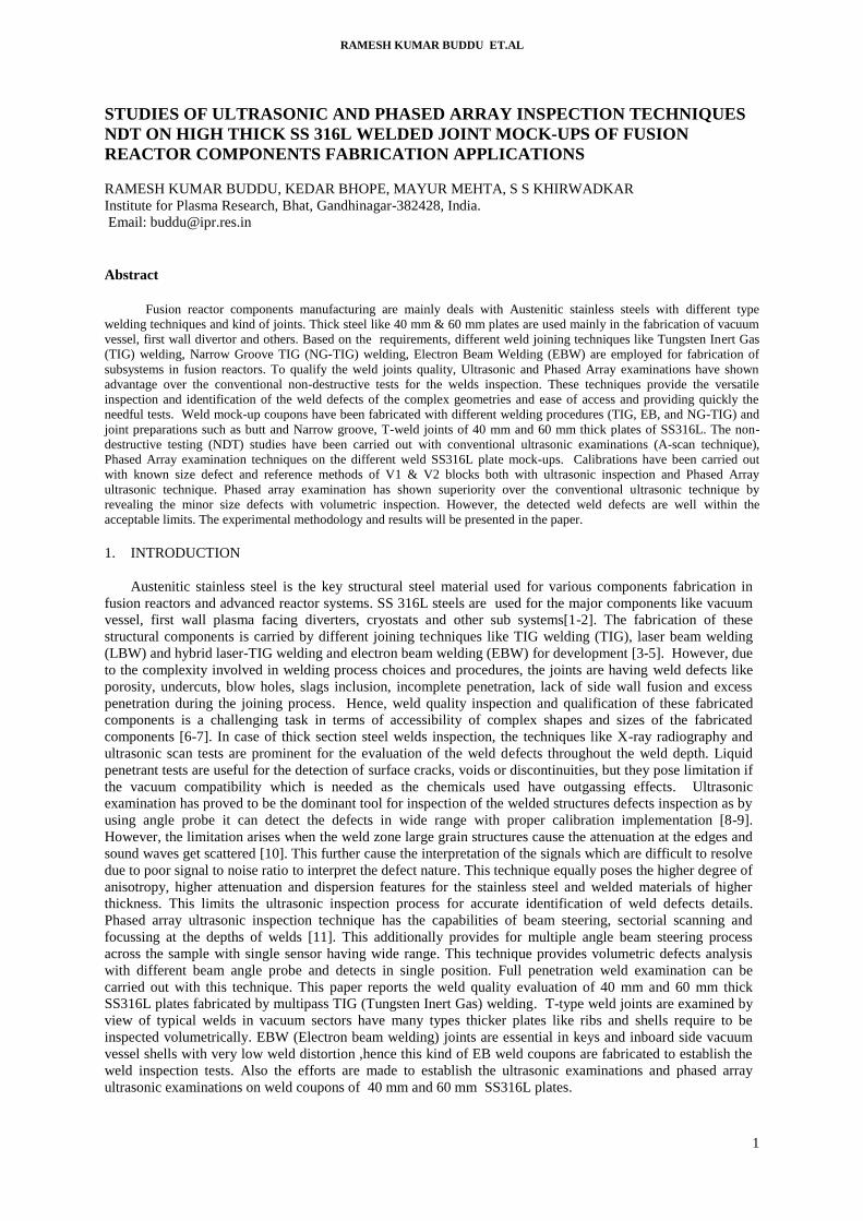
Some images of the fabricated SS316L welded mock-up coupons of 40 mm and 60 mm thick plates are shown
in Fig.1(a-e) for reference.
FIG. 1. Samples of different weld mock-ups (a) 60 mm thick TIG weld joint (b) 60 mm thick NG-TIG weld joint
(c) Electron Beam weld joint (d) 40 mm Thick T-type weld joint (e)60 mm thick T-weld joint
a b c
d e
RAMESH KUMAR BUDDU ET.AL
3
3. NDT EXAMINATIONS AND RESULTS
The different type SS316L weld samples fabricated of 40 mm and 60 mm thick SS316L plates are tested
with conventional NDT techniques like Visual inspection, Liquid penetrant examination, X-ray radiography,
ultrasonic conventional and phased array techniques for the weld defects analysis. All the fabricated thick weld
joints are subjected to the X-ray radiography examination for the weld defects evaluation across the weld zone
(butt V groove, narrow V groove and T-weld type) after preparation. The samples with butt V groove TIG
welding and T-TIG welding have been found to be free from any visible weld defects like porosity, lack of
penetration or lack of side wall fusion defects with radiography. As the thickness is higher, the intensity of the
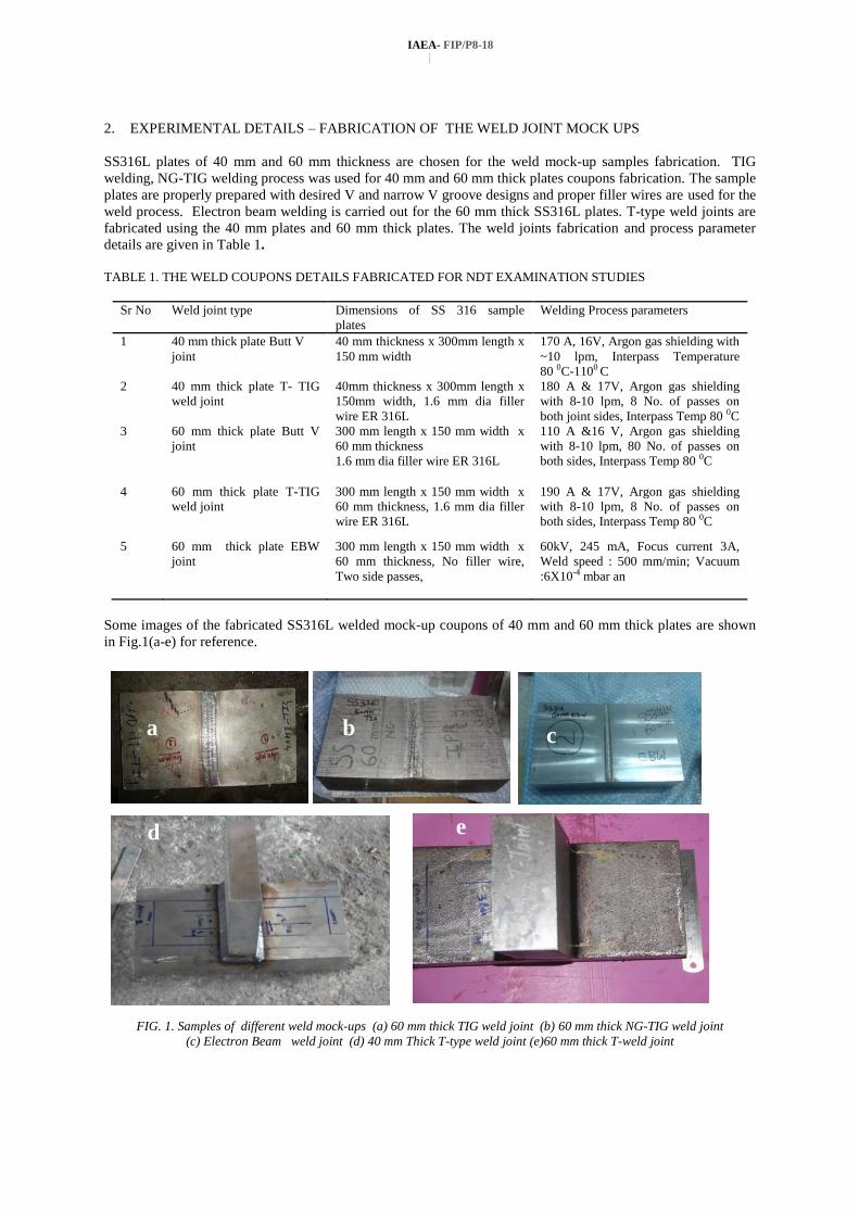
X-ray source requires high intensity to get the proper penetration for the weld defect observations. The samples
tested with X-ray radiography data are shown in Fig. 2(a) for reference for TIG welded sample of 60 mm butt V
joint and it has shown no significant observation of the weld defects present. And as shown in Fig. 2 (b) for 40
mm T-weld TIG sample, there is no noticeable weld defect present in the weld zone.
FIG. 2. X-ray radiography images of (a) 60 mm thick TIG weld joint (b) 40 mm Thick T-TIG weld joint
Similarly other welded joint plates of SS 316L of 40 mm and 60 mm thick TIG, T-TIG welded are examined
and there was no observation of any significant weld defects of noticeable size. In this contribution main
emphasis is given on ultrasonic conventional and phased array examinations studies carried and are discussed.
3.1 Ultrasonic examination studies
Ultrasonic A-scan examination has been carried out on the 40 mm and 60 mm thick TIG, T-TIG weld joints of
SS316L plates and 60 mm thick EBW samples which are given in Table 1. Pulse Echo reflection technique
with A scan procedure has been carried out by using angle probe (450, 10 mm diameter with 4 MHz ) for testing
of the weld coupons. In this testing process, the basic essential step is the calibration with known size defects
and Distance Amplitude Curve (DAC) generation with the reference V1and V2 standard blocks [12].
Ultrasonic equipment and the probe setup used for testing of weld flaw detection, are calibrated prior to
inspection is carried for the 40 mm and 60 mm thick SS 316 L TIG welds, Electron Beam welds and for
testing of weld defects. The procedure of the detailed calibration, DAC generation and inspection details
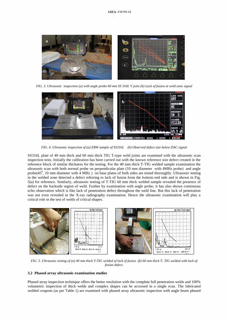
discussed in details [13]. SS316L weld of 60 mm thick V groove joint was shown for reference in Fig. 2(a),
and ultrasonic examination has shown the peak of the weld defect response of below DAC reference due to lack
of penetration which was observed at distance of 38 mm from bottom side and at 147.5 mm distance from edge
side. This was not revealed in the X-ray radiography data. This shows the ultrasonic testing has advantage over
the radiography technique which is not detected defects in higher thick welds. Similarly some of the samples are
noted with minor weld defects signatures like lack of penetration or porosity in the welded joints, but are within
the acceptable limits. In case of Electron beam welded joints, there was no significant observation of the weld
defects by ultrasonic scan examination and the samples are of acceptable quality. The reference is shown Fig.
3(a). Similarly EBW joint has shown reference peak of some amplitude revealing the typical defect size of
below DAC curve. However this was not revealed in the radiography test. The image of EBW sample observed
is shown in Fig. 4(a-b) for reference.
(a) (b)
IAEA- FIP/P8-18
[
a b
FIG. 3. Ultrasonic inspection (a) with angle probe 60 mm SS 316L V joint (b) Lack of fusion at weld zone signal
FIG. 4. Ultrasonic inspection of (a) EBW sample of SS316L (b) Observed defect size below DAC signal
SS316L plate of 40 mm thick and 60 mm thick TIG T-type weld joints are examined with the ultrasonic scan
inspection tests. Initially the calibration has been carried out with the known reference size defect created in the
reference block of similar thickness for the testing. For the 40 mm thick T-TIG welded sample examination the
ultrasonic scan with both normal probe on perpendicular plate (10 mm diameter with 4MHz probe) and angle
probe(450, 10 mm diameter with 4 MHz ) on base plates of both sides are tested thoroughly. Ultrasonic testing
in the welded zone detected a defect referring to lack of fusion from the bottom end side and is shown in Fig.
5(a) for reference. Similarly, ultrasonic testing of T-TIG 60 mm thick welded sample revealed the presence of
defect on the backside region of weld. Further by examination with angle probe, it has also shown continuous
echo observation which is like lack of penetration defect throughout the weld line. But this lack of penetration
was not even revealed in the X-ray radiography examination. Hence the ultrasonic examination will play a
critical role in the test of welds of critical shapes.
FIG. 5. Ultrasonic testing of (a) 40 mm thick T-TIG welded of lack of fusion (b) 60 mm thick T- TIG welded with lack of
fusion defect.
3.2 Phased array ultrasonic examination studies
Phased array inspection technique offers the better resolution with the complete full penetration welds and 100%
volumetric inspection of thick welds and complex shapes can be accessed in a single scan. The fabricated
welded coupons (as per Table 1) are examined with phased array ultrasonic inspection with angle beam phased
a b
b a
RAMESH KUMAR BUDDU ET.AL
5
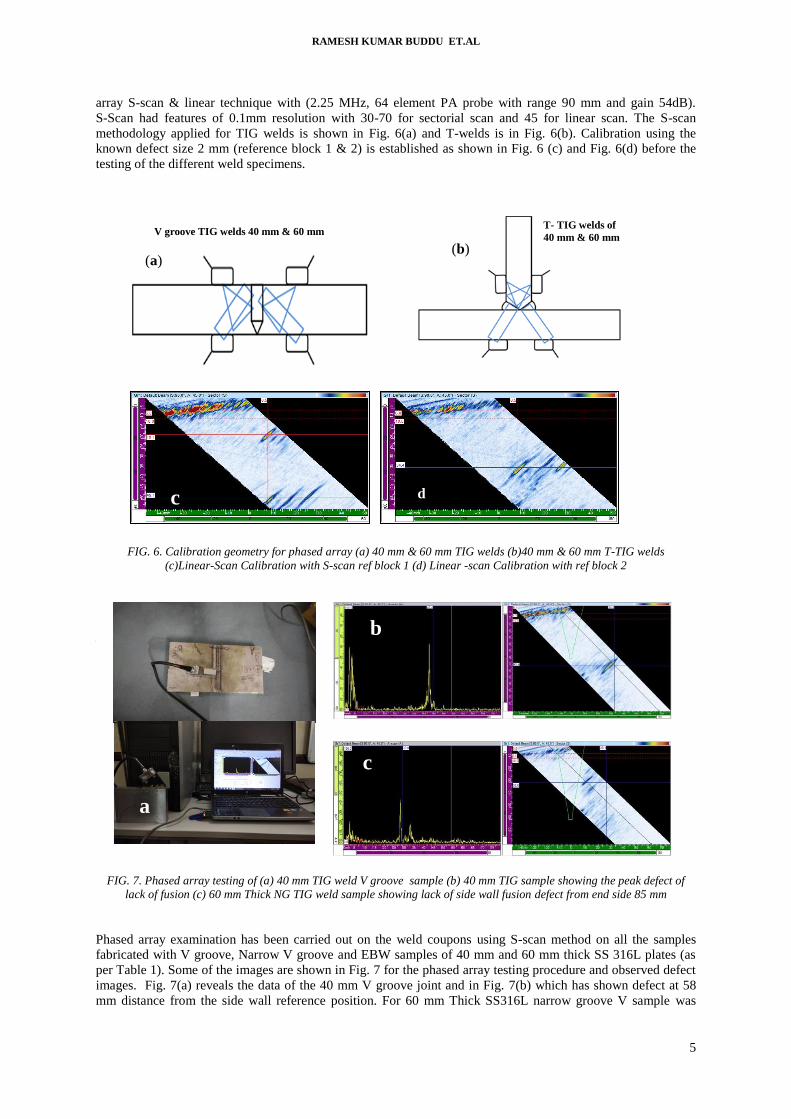
array S-scan & linear technique with (2.25 MHz, 64 element PA probe with range 90 mm and gain 54dB).
S-Scan had features of 0.1mm resolution with 30-70 for sectorial scan and 45 for linear scan. The S-scan
methodology applied for TIG welds is shown in Fig. 6(a) and T-welds is in Fig. 6(b). Calibration using the
known defect size 2 mm (reference block 1 & 2) is established as shown in Fig. 6 (c) and Fig. 6(d) before the
testing of the different weld specimens.
FIG. 6. Calibration geometry for phased array (a) 40 mm & 60 mm TIG welds (b)40 mm & 60 mm T-TIG welds
(c)Linear-Scan Calibration with S-scan ref block 1 (d) Linear -scan Calibration with ref block 2
FIG. 7. Phased array testing of (a) 40 mm TIG weld V groove sample (b) 40 mm TIG sample showing the peak defect of
lack of fusion (c) 60 mm Thick NG TIG weld sample showing lack of side wall fusion defect from end side 85 mm
Phased array examination has been carried out on the weld coupons using S-scan method on all the samples
fabricated with V groove, Narrow V groove and EBW samples of 40 mm and 60 mm thick SS 316L plates (as
per Table 1). Some of the images are shown in Fig. 7 for the phased array testing procedure and observed defect
images. Fig. 7(a) reveals the data of the 40 mm V groove joint and in Fig. 7(b) which has shown defect at 58
mm distance from the side wall reference position. For 60 mm Thick SS316L narrow groove V sample was
a
b
c
c
V groove TIG welds 40 mm & 60 mm T- TIG welds of
40 mm & 60 mm
(a) (b)
d
IAEA- FIP/P8-18
[
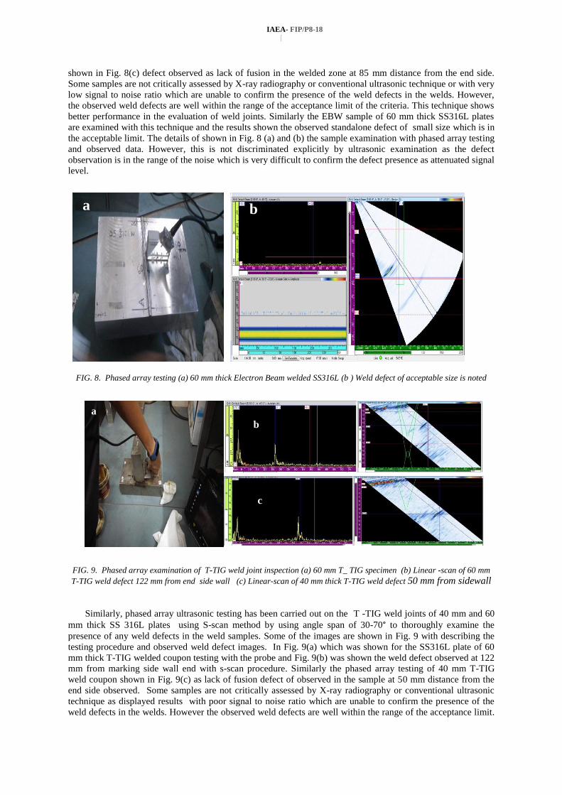
shown in Fig. 8(c) defect observed as lack of fusion in the welded zone at 85 mm distance from the end side.
Some samples are not critically assessed by X-ray radiography or conventional ultrasonic technique or with very
low signal to noise ratio which are unable to confirm the presence of the weld defects in the welds. However,
the observed weld defects are well within the range of the acceptance limit of the criteria. This technique shows
better performance in the evaluation of weld joints. Similarly the EBW sample of 60 mm thick SS316L plates
are examined with this technique and the results shown the observed standalone defect of small size which is in
the acceptable limit. The details of shown in Fig. 8 (a) and (b) the sample examination with phased array testing
and observed data. However, this is not discriminated explicitly by ultrasonic examination as the defect
observation is in the range of the noise which is very difficult to confirm the defect presence as attenuated signal
level.
FIG. 8. Phased array testing (a) 60 mm thick Electron Beam welded SS316L (b ) Weld defect of acceptable size is noted
FIG. 9. Phased array examination of T-TIG weld joint inspection (a) 60 mm T_ TIG specimen (b) Linear -scan of 60 mm
T-TIG weld defect 122 mm from end side wall (c) Linear-scan of 40 mm thick T-TIG weld defect 50 mm from sidewall
Similarly, phased array ultrasonic testing has been carried out on the T -TIG weld joints of 40 mm and 60
mm thick SS 316L plates using S-scan method by using angle span of 30-70° to thoroughly examine the
presence of any weld defects in the weld samples. Some of the images are shown in Fig. 9 with describing the
testing procedure and observed weld defect images. In Fig. 9(a) which was shown for the SS316L plate of 60
mm thick T-TIG welded coupon testing with the probe and Fig. 9(b) was shown the weld defect observed at 122
mm from marking side wall end with s-scan procedure. Similarly the phased array testing of 40 mm T-TIG
weld coupon shown in Fig. 9(c) as lack of fusion defect of observed in the sample at 50 mm distance from the
end side observed. Some samples are not critically assessed by X-ray radiography or conventional ultrasonic
technique as displayed results with poor signal to noise ratio which are unable to confirm the presence of the
weld defects in the welds. However the observed weld defects are well within the range of the acceptance limit.
a
c
b
a b
RAMESH KUMAR BUDDU ET.AL
7
This technique shows better performance in the evaluation of weld joints. Similarly the EBW sample of 60 mm
thick SS316L plates are examined with this technique and the results shown the observed standalone defect
which is in the acceptable limit. However this observation of defect is not explicitly discriminated by ultrasonic
examination as the defect observation is in the range of the noise which is very difficult to confirm the defect
presence as attenuated signal level. Phased array has shown the better performance when compared to the
conventional ultrasonic technique in order to examine the minute weld defects. Also volumetric examinations
and full penetration tests of the complex shapes and size of higher thickness welds are quiet accessible with this
technique.
4. CONCLUSIONS
SS316L plates of different kind welded joints of 40 mm and 60 mm thick are fabricated by using TIG, Narrow
V groove TIG and Electron beam welding processes. T-TIG weld joints of 40 mm and 60 mm thick plate weld
mock-ups are fabricated to establish the NDT examinations. All the welded mock-ups are examined with
conventional NDT techniques (Visual inspection, Liquid penetrant examination and X-ray radiography) for
weld defects examination. Efforts are given mainly to study and establish the conventional ultrasonic
examination and phased array examination procedures on the different kind weld mock-ups fabricated.
Ultrasonic examination has been carried out with proper calibration using the standard V1 and V2 references
with known size defects for DAC generation and interpretation. Lack of fusion defects are observed in some of
the welded joints of 40 mm and 60mm thick SS316L mock-ups. These were not revealed in the X-ray
radiography examination explicitly. However, ultrasonic tests will pose limitations when there are some defects
of small size are present due to the attenuation of the source beam. Phased array examination has been carried
on all the welded joints fabricated. This technique has shown some more weld defects like lack of fusion in TIG
welds which are unrevealed by ultrasonic scan examination and radiography techniques.
ACKNOWLEDGEMENTS
Mr. Ramesh Kumar Buddu is highly indebted to the extensive contributions from Mr S.S. Shaikh , Mr. H.D.
Kotadiya, Mr.K. Nayak and K.S. Garasiya at various stages of the presented work on weld mock-ups
fabrication, NDT testing and fruitful discussions.
REFERENCES
[1] V.BARABASH, A. PEACOCK, S.FABRITSIEV, G.KALININ, S.ZINKLE, A.ROWCLIFFE, et.al, The ITER
International Team, Materials challenges for ITER – Current status and future activities, Journal of Nuclear Materials
367–370 (2007) 21–32.
[2] K. IOKI et. al., “Design Improvement and R&D achievements for VV and in Vessel components towards ITER
construction”, Nuclear Fusion 43 (2003) 268-273.
[3] A. SANDERSON, C.S. PUNSHON, J.D. RUSSELL., Advanced welding processes for fusion reactor fabrication,
Fusion Engineering and Design 49–50 (2000) 77–87.
[4] G. KALININ ET. AL. “ITER R&D: “Vacuum Vessel and In-Vessel Components: Materials Development and Test”,
Fusion Engineering and Design 55 (2001) 231-246.
[5] RK BUDDU, NL CHAUHAN, PM RAOLE, Investigations of Microstructure and Mechanical Properties of 60-mm-
Thick Type 316L Stainless Steel Welded Plates by Multipass Tungsten Inert Gas Welding and Electron Beam Welding
for Fusion Reactor Applications, Fusion Science & Technology 65 (2), 248-255.
[6] RAFAEL MARTÍNEZ-ONA, ANDRÉS GARCÍA, MARÍA C.PÉREZ, GIORGIA PIROLA, ANDRÉS DANS,
ÁNGEL BAYÓN, Ultrasonic inspections in the fabrication of the ITER vacuum vessel sectors, Fusion Engineering and
Design 88 (2013) 2155– 2159.
[7] G.H. KIM, C.K.PARKS.W.JINH.S.KIMK.H.HONGY.J.LEEH.J.AHN, W.CHUNG, Y.H.JUNG, B.R.ROHBJ.
W.SACC .H.CHOI, Qualification of phased array ultrasonic examination on T-joint weld of austenitic stainless steel
for ITER vacuum vessel, Fus Eng Des 109-11192016) 1099-1103.
[8] BALDEV RAJ, Non Destructive Testing of Welds, Narosa Publishing, New Delhi (2000).
[9] P.O. MOORE (Ed.), Non destructive Testing Handbook, vol. 7, Ultrasonic Testing, 3rd ed., American Society for Non
Destructive Testing, Inc., Columbus, USA, 2007.
IAEA- FIP/P8-18
[
[10] Y RAVICHANDRAN, P.S.SANATH THAMPI, SURESH JAKKULA,G.SELVAKUMAR, T. C. KARTHIKEYAN,
PEMMARAJU RAGHAVENDRA, Phased Array Ultrasonic Testing for Heavy Wall Austenitic Stainless Steel Welds,
26th National Seminar & International Exhibition On NON-DESTRUCTIVEEVALUATION during 15th -17th
December 2016, held at Thiruvananthapuram, India.
[11] ALOK PRAKASH,N JOTHILAKSHMI, PARITOSH NANEKAR, A B MUKHERJEE, R S YADAV, Phased array
ultrasonic inspection of weld joints of steam generators of PWRS, 14th APCNDT-2013, Mumbai, India, November 18-
22, 2013. Paper 90.
[12] L E MAGGI, C E R SILVA, A V ALVARENGA, R P B COSTA-FELIX, Ultrasonic calibration and certification of V1
and V2 type reference standard blocks for use in Non-Destructive Testing, Journal of Physics: Conference Series 279
(2011) 012029.
[13] RAMESH KUMAR BUDDU, SHAMSUDDIN SHAIKH, P.M. RAOLE, B SARKAR, Weld defects analysis of 60 mm
thick SS316L mock-ups of TIG and EB welds by Ultrasonic inspection for fusion reactor vacuum vessel applications.
25th National Seminar & International Exhibition On NON-DESTRUCTIVEEVALUATION (NDE-2015) held during
26th-28th November 2015, Hyderabad, India.