Embed Size (px)
Citation preview

Structure Related Noise
Presentation by:Harvey Knauer, P.E.
Environmental Acoustics,A Division of Gannett Fleming, Inc.
NCHRP Report 791 Supplemental Guidance on the Application of FHWA's
Traffic Noise Model (TNM)
Prepared for: National Cooperative Highway Research
Program (NCHRP) Transportation Research Board of The National
Academies
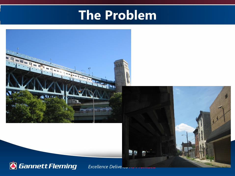
The Problem
Structure-Related Noise• Structure-Reflected Noise
• Structure-Radiated Noise from:Expansion Joints Bridge Decks
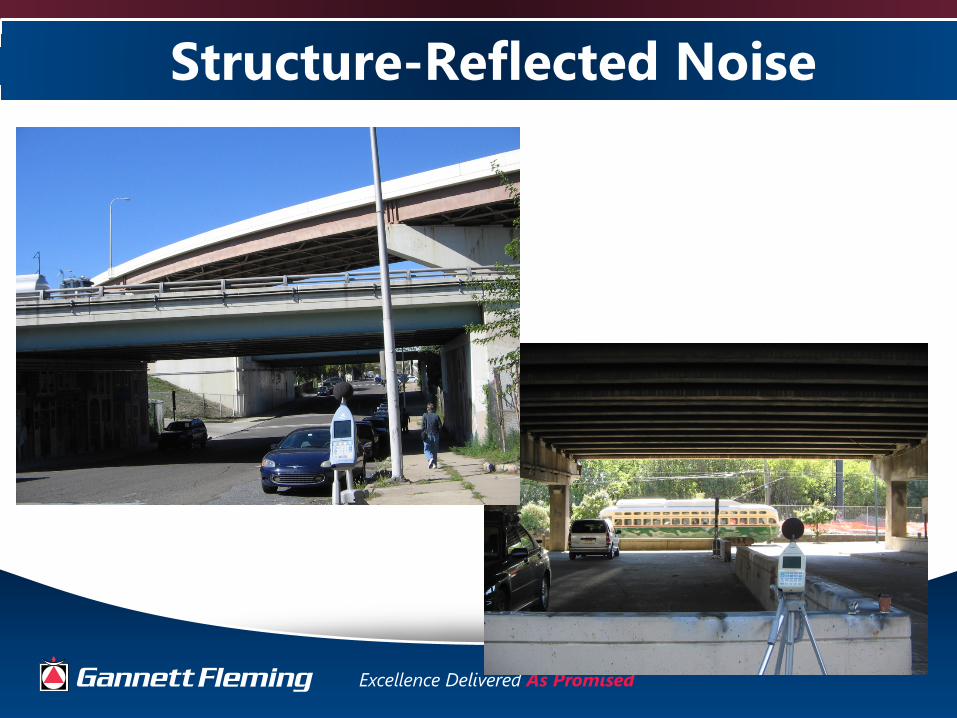
Structure-Reflected Noise

Structure-Radiated Noise

The Approach
• Compile and/or Develop Modeling Techniques
• Evaluate Modeling Techniques
• Test/Compare Modeling Techniques
• Determine Best Modeling Practices
Modeling Techniques Evaluated
• Technique #1: FHWA TNM modeling of reflected noise by developing image receptors (Also included comparative measurements)
• Technique #2: Using noise measurement data to develop combined structure-related predicted noise levels
• Technique #3: Isolating individual components of structure-radiated noise using noise measurements (Addressed during evaluations of Techniques #1 and #2)

Modeling Technique #1• Model direct path of noise from the noise source (vehicles on
structure) to receptors using FHWA TNM.
• For each affected receptor, calculate noise levels from reflected sources using method described in Reiter/Bowlby paper titled Using the FHWA Traffic Noise Model (FHWA TNM) to Assess Noise Reflections Off Of the Underside of Elevated Bridge Structures.
• At each affected receptor, add reflected noise level to the direct noise level generated in base FHWA TNM run to obtain total noise level.
NOTE: This technique only addresses reflected noise and does not account for effects of structure-radiated noise from deck or expansion joints.
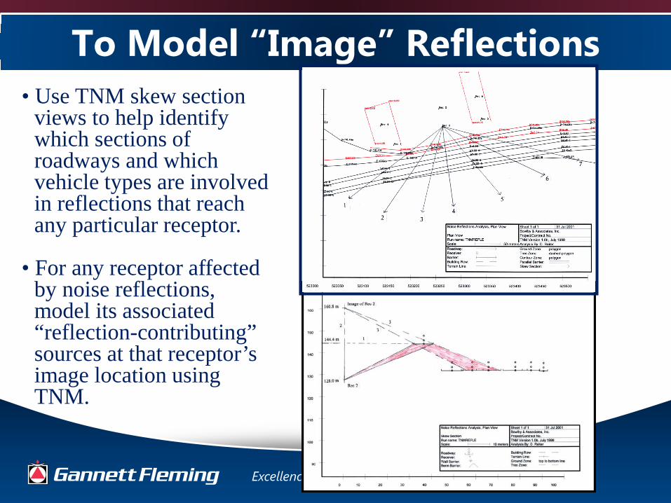
To Model “Image” Reflections• Use TNM skew section
views to help identify which sections of roadways and which vehicle types are involved in reflections that reach any particular receptor.
• For any receptor affected by noise reflections, model its associated “reflection-contributing” sources at that receptor’s image location using TNM.

Comparison of Modeling Technique #1
• Reflective and Non-Reflective Sites I-40 Nashville, TN
Modeled Leq(h) Noise Level with Barrier and
Reflections
Estimated Degradation of Barrier Insertion Loss
due to Reflections
Measured Leq Noise
Level
Measured Leq in dB(A)
dB(A) dB dB(A) dB(A) dB
1 72 5 Embankment, Elevated Ramp
73Embankment, No
Ramp and Retaining Wall No Ramp Near
65 8
2 74 5Retaining Wall,
Elevated Ramp Far Site
70 Retaining Wall No Ramp Far Site
67 3
3 72 4Retaining Wall,
Elevated Ramp Far Site
70 Retaining Wall, No Ramp Far Site
67 3
Average > 4.7 Average > 4.7
Estimated Effect of
Reflections
Data from Screening Analysis (from 2001 Reiter/Bowlby Report)
Site I.D. Description Description
Comparable 2013 Noise Measurement Site Affected by
Reflections
Comparable 2013 Noise Measurement Site Not Having
Reflections
Average predicted effect of reflected noise using Technique #1 was similar to effects determined via measurements.

Modeling Technique #2• Model direct path of noise from the noise source
(vehicles on structure) to receptors using FHWA TNM.
• Conduct noise measurements of combined structure-related noise levels underneath and adjacent to structure.
• Based on noise measurements, develop formulae to model structure-related noise levels at locations adjacent to structure.
• Add reflected noise levels to the direct noise levels generated in base FHWA TNM run to obtain total noise levels at adjacent receptors.

Noise Measurements Underneath I-95
Position 1: Near Joint, within 5
feet of Bottom of Deck
Position 2: Away From Joint, within 5
feet of Bottom of Deck
Position 3: 5 feet Above Ground
between Positions 1 and 2
Leq Leq Leq
3:47pm 63.6 63.2 63.1
4:08pm 64.4 64.1 64.2
4:24pm 64.2 64.2
Measured Noise Level, Leq in dB(A)
DateBeginning
Time of Measurement
4/15/2013
Measurements of deck and expansion joint noise under I-95 near Schiller Street
Little difference in noise levels underneath structure. Therefore, measurement taken at drip edge location would represent combined noise level due to deck and joint noise.
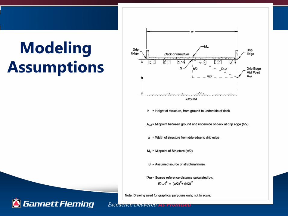
Modeling Assumptions

Noise Measurements at Drip Edge and Adjacent to Structure
Measurements Adjacent to Structure

Formula for Drop Off with DistanceFor 3 dB/DD Drop-Off Rate: LAx = LDE – 10 Log10 (DAP/DRef)
For 4.5 dB/DD Drop-Off Rate: LAx = LDE – 15 Log10 (DAP/DRef)
For 6 dB/DD Drop-Off Rate: LAx = LDE – 20 Log10 (DAP/DRef)
Where:LDE = Leq noise measurement in dB(A) taken at 5 feet above
ground under structure drip edgeLAx = Calculated structure-related noise level at an analysis
point Ax, located x feet from the drip edgeDAP = Distance from point S to the analysis point AxDRef = Distance from point S to Point ARef
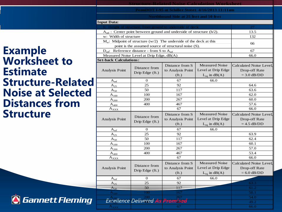
Example Worksheet to Estimate Structure-Related Noise at Selected Distances from Structure
Input Data: h: Height of structure, from ground to underside of deck 27 Aref : Center point between ground and underside of structure (h/2). 13.5
132 Mw: Midpoint of structure (w/2) The underside of the deck at this point is the assumed source of structural noise (S).
6766.0
Set-back Calculations:
Aref 0 67 66.0A25 25 92 64.6A50 50 117 63.6A100 100 167 62.0A200 200 267 60.0A400 400 467 57.6AXXX 67 66.0
Aref 0 67 66.0A25 25 92 63.9A50 50 117 62.4A100 100 167 60.1A200 200 267 57.0A400 400 467 53.4AXXX 67 66.0
Aref 0 67 66.0A25 25 92 63.3A50 50 117 61.2A100 100 167 58.1A200 200 267 54.0A400 400 467 49.2AXXX 67 66.0
PennDOT I-95 at Schiller Street 4/16/2013 11:11am
Northbound Side at 25 feet and 50 feet
Structure-Related Noise Calculation Worksheet
Analysis PointDistance from Drip Edge (ft.)
Distance from S to Analysis Point
(ft.)
Measured Noise Level at Drip Edge
Leq in dB(A)
Calculated Noise Level, Drop-off Rate = 3.0 dB/DD
w: Width of structure
Dref: Reference distance - from S to Aref
Measured Noise Level at Drip Edge, dB(A)
66
Analysis PointDistance from Drip Edge (ft.)
Distance from S to Analysis Point
(ft.)
Measured Noise Level at Drip Edge
Leq in dB(A)
Calculated Noise Level, Drop-off Rate = 6.0 dB/DD
Measured Noise Level at Drip Edge
Leq in dB(A)
Calculated Noise Level, Drop-off Rate = 4.5 dB/DD
Analysis PointDistance from Drip Edge (ft.)
Distance from S to Analysis Point
(ft.)

Testing of Modeling Technique #2
• I-95 Sections GIR and AFC Projects in Phila., PA– 5 locations– Comparison with EA 2010 and 2012 measurements
• PA Turnpike Bridge over Susquehanna River– 5 locations– Comparison with EA 2010 and 2012 measurements
• Indiana DOT project– Comparison with Bowlby 2012 measurements
• Arkansas DOT project– Comparison with Bowlby 2008 measurements

I-95 Projects in Philadelphia, PA

PA Turnpike Bridge over Susquehanna River

Indiana DOT Project
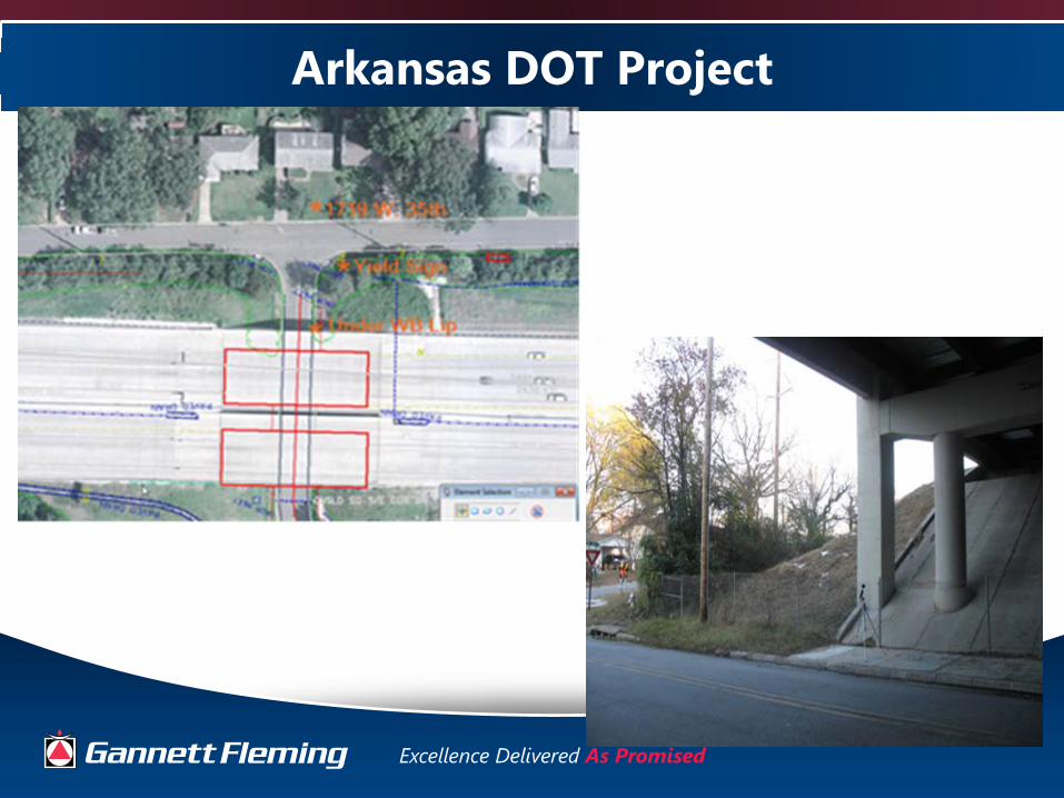
Arkansas DOT Project
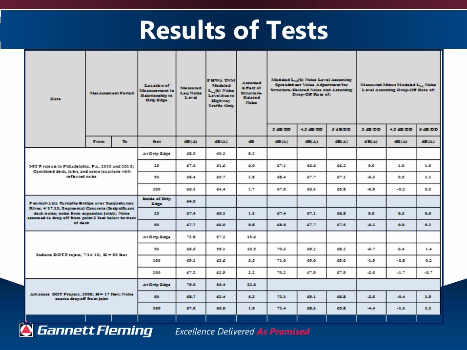
Results of Tests
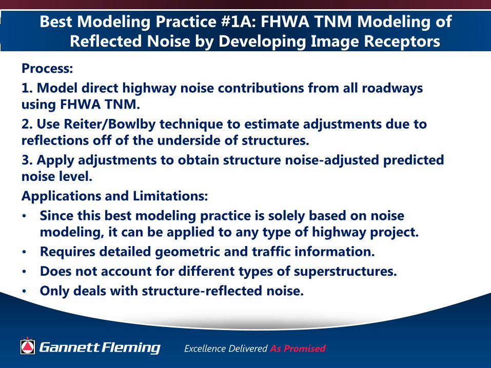
Best Modeling Practice #1A: FHWA TNM Modeling of Reflected Noise by Developing Image Receptors
Process: 1. Model direct highway noise contributions from all roadways using FHWA TNM.2. Use Reiter/Bowlby technique to estimate adjustments due to reflections off of the underside of structures.3. Apply adjustments to obtain structure noise-adjusted predicted noise level.Applications and Limitations:• Since this best modeling practice is solely based on noise
modeling, it can be applied to any type of highway project.• Requires detailed geometric and traffic information.• Does not account for different types of superstructures.• Only deals with structure-reflected noise.

Best Modeling Practice #1B: Noise Measurements at Comparable Sites - With and Without Reflections
Process: 1. Model direct highway noise contributions from all roadways using FHWA TNM. 2. Conduct noise measurements at selected setback locations where reflective noise is believed to be a contributing factor.3. Conduct simultaneous measurements at “non-reflecting” locations with similar setbacks, traffic, and topography. 4. For each measurement setback distance, calculate the difference between the values for items 2 and 3, above. This is the reflective noise adjustment factor.5. For each measurement setback distance, apply the item 4 reflected noise adjustment factor to the FHWA TNM value from Item 1 to obtain the structure noise-adjusted predicted noise level.
Applications and Limitations: Same as BMP #1A

Best Modeling Practice #2: Noise Measurement Data Used to Develop Structure-Related Noise Adjustments
Process: 1. Model direct highway noise contributions from all roadways
using FHWA TNM. 2. Conduct noise measurements at the drip edge ground level
location and at a minimum of two (2) setback distances for purposes validating the FHWA TNM runs and determining the extent of structure-related noise contributions.
3. Apply the adjustments from the appropriate Structure-Related Noise Calculation Worksheet to levels at setback locations to determine total modeled noise levels at each setback location.

Best Modeling Practice #2: Noise Measurement Data Used to Develop Structure-Related Noise Adjustments
Process (cont.):4. If expansion joint noise is the predominant structure-related
noise source, assume that the noise source emanates from the joint above the measurement point rather than at the midpoint of the structure, and adjust the Worksheet Dref value to be the distance from the drip edge microphone to the bottom of the structure’s deck.
5. Apply the Worksheet values to FHWA TNM predicted levels for the proposed project using the drop-off rates that best correlate with the measured levels.

Best Modeling Practice #2: Noise Measurement Data Used to Develop Structure-Related Noise Adjustments
Applications and Limitations:• Requires detailed geometric and traffic information.• Most applicable for reconstruction and/or widening projects• Take measurements at structures that resemble the structure
type and configuration that nearest replicates that planned for the proposed highway improvement project.
• Requires exclusion of extraneous noise sources• Requires sufficient equipment and manpower to perform
simultaneous measurements of noise and traffic• Does not account for any reflected noise from other highway
noise sources that affects setback locations unless such reflected noise reaches the ground-level drip edge location