Embed Size (px)
Citation preview

Structure Inspection Manual Part 2 – Bridges Appendices
March 2011 2-A-i
Table of Contents
APPENDIX A: REFERENCES ....................................................................................... 1
APPENDIX B: FORMS ................................................................................................... 5
SECTION B.1 STRUCTURE INVENTORY AND APPRAISAL FIELD REVIEW (DT2006) .................................................................................................................... 5
SECTION B.2 BRIDGE INSPECTION REPORT (DT2007) ...................................... 9
SECTION B.3 BRIDGE INSPECTION SUPPLEMENTAL REPORT (DT2008)....... 21
SECTION B.4 BRIDGE IN-DEPTH INSPECTION REPORT (DT2009) .................. 25
SECTION B.5 BRIDGE FRACTURE CRITICAL INSPECTION REPORT (DT2010) ................................................................................................................................. 29
SECTION B.6 BRIDGE FRACTURE CRITICAL INSPECTION SUPPLEMENTAL REPORT (DT2011) .................................................................................................. 33
SECTION B.7 STREAMBED PROFILE INSPECTION REPORT (DT2012) ........... 37
SECTION B.8 UNDERWATER BRIDGE INSPECTION – DIVE LOG (DT2013)..... 41
APPENDIX C: FATIGUE PRONE DETAILS ................................................................ 45
APPENDIX D: STATE MEASUREMENT CONVENTIONS .......................................... 51
SECTION D.1 GIRDER MEASUREMENT CONVENTIONS .................................. 51
SECTION D.2 TRUSS MEASUREMENT CONVENTIONS .................................... 54
SECTION D.3 DECK MEASUREMENT CONVENTIONS ...................................... 55
SECTION D.4 ABUTMENT AND WINGWALL LENGTH MEASUREMENT CONVENTIONS....................................................................................................... 56
APPENDIX E: FRACTURE CRITICAL DETAILS ......................................................... 57

Structure Inspection Manual Part 2 – Bridges Appendices
March 2011 2-A-ii
[THIS PAGE INTENTIONALLY LEFT BLANK]

Structure Inspection Manual Part 2 – Bridges Appendix A: References
March 2011 2-A-1
APPENDIX A: REFERENCES
AASHTO. “The Maintenance and Management of Roadways and Bridges”. AASHTO Maintenance Manual, 1999.
AASHTO. Foundation Investigation Manual, 1978.
AASHTO. Guide Specifications and Commentary for Vessel Collision Design of Highway Bridges, 1991.
AASHTO. Guide Specifications for Fatigue Evaluation of Existing Steel Bridges, 1990.
AASHTO. Guide Specifications for Horizontally Curved Highway Bridges, 1993.
AASHTO. Guide Specifications for Strength Evaluation of Existing Steel and Concrete Bridges, 1989.
AASHTO. Guidelines for Bridge Management Systems, 1993.
AASHTO. Manual for Condition Evaluation of Bridges, 2000.
AASHTO. Manual for Maintenance Inspection of Bridges, 1983.
AASHTO. Movable Bridge Inspection, Evaluation, and Maintenance Manual, 1998.
AASHTO. Standard Specifications for Highway Bridges. 16th Edition, 1996.
AASHTO. Standard Specifications for Movable Highway Bridges, 1988.
ACI. Guide for Making a Condition Survey of Concrete in Service, 1984
ACI. Testing Hardened Concrete: Nondestructive Methods, 1976.
AISC. Manual of Steel Construction, 9th Edition, 1989.
AISI. Steel Bridge Bearing Selection and Design Guide, Vol. II, Chap. 4, Highway Structures Design Handbook, 1996.
American Society for Nondestructive Testing. American Society of Nondestructive Testing Handbook. Vols. I&II, 1982.
American Welding Society. Guide for the Nondestructive Inspections, 1977.
Beall, Christine, Masonry Design and Detailing, 1984.
Brockenbrough, Roger L., and Merritt, Frederick S., Structural Steel Designer’s Handbook, Second Ed., 1994.
Commonwealth of Pennsylvania Department of Transportation, Yen, Ben T., Huang, Ti, Lai, Lung-Yang, and Fisher, John W. Manual for Inspecting Bridges for Fatigue Damage Conditions, 1990.

Structure Inspection Manual Part 2 – Bridges Appendix A: References
March 2011 2-A-2
Departments of the Army and the Air Force. Bridge Inspection, Maintenance, and Repair, 1994.
FHWA. Technical Advisory: Scour at Bridges, 1988.
FHWA. Advanced Bridge Inspection Methods: Applications and Guidelines, 1989.
FHWA. Benchmark for Maine Department of Transportation A588 Weathering Steel, 1989.
FHWA. Bridge Inspector's Manual for Movable Bridges, 1977.
FHWA. Cable-Stayed Bridges, 1978.
FHWA. Corrosion and Cathodic Protection of Steel Reinforced Concrete Bridge Decks, 1988.
FHWA. Countermeasures for Hydraulic Problems at Bridges. Vols. I&II, 1978.
FHWA. Culvert Inspection Manual, 1997.
FHWA. Fatigue Cracking of Steel Bridge Structures. Vols. II&III, 1990.
FHWA. Highways in the River Environment, 1988.
FHWA. “Inspection of Bridge Timber Piling”. Operations and Analysis Manual, 1989.
FHWA. Inspection of Fracture Critical Bridge Members, 1986.
FHWA. Inspection of Steel Bridges for Fatigue Damage, 1981.
FHWA. Methods for Assessment of Stream Related Hazards to Highways and Bridges, 1982.
FHWA. Recording and Coding Guide for the Structure Inventory and Appraisal of the Nation’s of Bridges, 1988.
FHWA. Underwater Inspection of Bridges, 1989.
Forest Products Society, Wood Handbook, 1999.
Gaylord, Edwin H., and Gaylord, Charles N., Structural Engineering Handbook, Third Ed., 1990.
Jefferson, T.B., and Woods, Gorham. Metals and How to Weld Them, Second Ed., 1990.
Krautkramer. Ultrasonic Testing of Materials. Third Ed., 1983.
Mac Gregor, James G. Reinforced Concrete Mechanics and Design, 1988.
Marine Technology Society. Operational Guidelines for Remotely Operated Vehicles, 1984.

Structure Inspection Manual Part 2 – Bridges Appendix A: References
March 2011 2-A-3
Naval Civil Engineering Laboratory. “Inspection Requirements Analysis and Nondestructive Testing Technique Assessment”. Underwater Inspection of Waterfront Facilities, 1982.
Naval Facilities Engineering Command. Inspection of Wood Beams and Trusses, 1985.
Park, Sung H. Bridge Inspection and Structural Analysis, 1980.
Parsons Brinckerhoff, Bridge Inspection and Rehabilitation, 1993.
Raina, V. K., Concrete Bridges, 1994.
Road Research Laboratory. Nondestructive Testing of Concrete, 1962.
Salmon, Charles G., and Johnson, John E. Steel Structures, Third Ed., 1990.
Tonias, Demetrios E. Bridge Engineering, 1995.
US Army Corps of Engineers. Development of Nondestructive Testing Systems for In Situ Evaluation of Concrete Structures, 1987.
USDA. Decay in Wood Bridges, 1977.
USDA. Forest Service Inspection of Bridges Using Stress Wave Timing Nondestructive Evaluation Tools, April 1999.
USDA. Timber Bridges, 1992.
USDOT. Bridge Inspectors Training Manual/90, Revised 1995.
USDOT. Inspection of Fracture Critical Bridge Members, 1986.
USDOT. Nondestructive Testing Methods for Steel Bridges-Training Manual, 1986.
USDOT. Recording and Coding Guide for the Structure Inventory and Appraisal of the Nation's Bridges. Report No. FHWA-PD-96-001, December 1995.
USDOT. Revisions to the National Bridge Inspection Standards, 1988.
USDOT. Safety Inspection of In-Service Bridges, 1992.
USDOT. Safety Inspection of In-Service Bridges. Vol. 1, 1994.
USDOT. Safety Inspection of In-Service Bridges. Vol. 2, 1994.
USDOT. Safety Inspection of In-Service Bridges. Vol. 3, 1994.
USDOT. Underwater Evaluation and Repair of Bridge Components, 1995.
USDOT. Underwater Inspection of Bridges, 1989.

Structure Inspection Manual Part 2 – Bridges Appendix A: References
March 2011 2-A-4
White, Kenneth R., Minor, John, Derucher, Kenneth N., Bridge Maintenance Inspection and Evaluation, Second Ed., 1992.
Wisconsin DOT. Division of Highway and Transportation Services. State Highway Maintenance Manual, 1991.

Structure Inspection Manual Part 2 – Bridges Appendix B: Forms
March 2011 2-A-5
APPENDIX B: FORMS
SECTION B.1 STRUCTURE INVENTORY AND APPRAISAL FIELD REVIEW (DT2006)

Structure Inspection Manual Part 2 – Bridges Appendix B: Forms
March 2011 2-A-6
[THIS PAGE INTENTIONALLY LEFT BLANK]

Page 1 of 1
STRUCTURE INVENTORY AND APPRAISAL FIELD REVIEW Wisconsin Department of Transportation
DT2006 2010
Structure Number ____________________ Identification State (1)
Bridge Number (8) Facility Carried (7)
Location (9)
Route - On/Under (5A) Route Signing Prefix (5B)
Level of Service (5C)
Route Number (5D) Directional Suffix (5E)
% Responsibility
SHD District (2) County Code (3)
Place Code (4)
Kilometer Post (11) Feature Intersected (6)
Latitude (16)
Longitude (17) Border Bridge Code (98)
Border Bridge Number (99)
Age and Service Year Built (27)
Year Reconstructed (106) Type of Service On (42A)
Type of Service Under (42B)
Lanes On (28A) Lanes Under (28B)
Detour Length (19)
ADT (29) Truck ADT (109)
Year of ADT (30)
Geometric Data Length of Maximum Span (48)
Structure Length (49) Curb/Sidewalk Width L (50A)
Curb/Sidewalk Width R (50B)
Width Curb to Curb (51) Width Out to Out (52)
Approach Roadway Width (W/Shoulders) (32)
Median (33) Deck Area
Skew (34)
Structure Flared (35) Minimum Vertical Clearance over Bridge (53)
Minimum Vertical Underclearance Reference (54A)
Minimum Vertical Underclearance (54B)
Minimum Lateral Underclearance Reference (55A)
Minimum Lateral Underclearance R (55)
Minimum Lateral Underclearance L (56)
Structure Type and Material Number of Approach Spans (46)
Number of Spans Main Unit (45) Main Span Material & Design Type
Deck Type (107)
Wearing Surface (108A) Membrane (108B)
Deck Protection (108C)
Frequency (91) Inspection Date (90)
Next Inspection
FC Frequency (92A) FC Frequency (93A)
Next FC Inspection
UW Frequency (92B) UW Inspection (93B)
Next UW Inspection
SI Frequency (92C) SI Inspection (93C)
Next SI Inspection
Element Frequency Element Inspection Date
Next Element Inspection
Appraisal Bridge Rail (36A)
Transition (36B) Approach Rail (36C)
Underclearances, Vertical & Horizontal (69)
Waterway Adequacy (71)
Approach Roadway Alignment (72)
Scour Critical Bridges (113)
Navigation Data Navigation Control (38)
Navigation Clearance (39) Horizontal Clearance (40)
Pier Protection (111)
Lift Bridge Vertical Clearance (116)
[THIS PAGE INTENTIONALLY LEFT BLANK]

Structure Inspection Manual Part 2 – Bridges Appendix B: Forms
March 2011 2-A-9
SECTION B.2 BRIDGE INSPECTION REPORT (DT2007)

Structure Inspection Manual Part 2 – Bridges Appendix B: Forms
March 2011 2-A-10
[THIS PAGE INTENTIONALLY LEFT BLANK]

Page 1 of 10
BRIDGE INSPECTION REPORT Wisconsin Dept. of Transportation
DT2007 2010 (Replaces DT1544) s.84.17 Wis. Stats. Inventory Data Feature On: Maintainer: Structure Number Feature Under: Sect/Twn/Rng: Location: County: Municipality: Inv Rating: Rdwy Width: Deck Width: Existing Posting: Oper Rating: Total Length: Deck Area: ADT On: Yr: ADT Under: Yr: Inspection Type ( * = Additional Applicable Form(s) Required) Routine Visual Fracture Critical* In-Depth* UW-Dive* UW-Surv.* UW-Probe/
Visual* Movable*
Last Insp. Frequency Recom. Freq. Initial* Damage Interim Load Posted SI & A Field Review* Last Insp. Frequency N/A Recom. Freq. N/A Item No. Needing Change Load Rating Information
Overburden File Meas. (in): File Insp. Date: Insp. Meas. (in): Type: Section Loss File Meas. (%): File Insp. Date: Insp. Meas. (%): Describe: Should structure be re-rated for load carrying capacity? (Y/N) Reason: Date last rated: Expansion Joints Temp. Signing Condition
Location Type File Insp. Date
File Insp. (in.)
New Insp. (in.)
Type of Marker File Y N N/A
Comments
Bridge Markers Narrow Bridge One Lane Road Vertical Clearance Weight Limit Other(Addl. Sign) Clearances (Cardinal = N or E) File Meas. (ft.) File Date New Meas. (ft.) Min. Vertical Clearance Under (Cardinal) Min. Vertical Clearance Under (Non-Cardinal) Min. Vertical Clearance On Structure Type Construction/Rehabilitation History Material Configuration # of
Spans Overall Length Year Work Performed Plan Shop
Inspection Information Special Requirements Y/N Comments Traffic Control Access Equipment Other Inspector Information Team Leader Name and No. Printed Team Member(s) Name(s) Printed
Team Leader Signature Insp. Date Inspection Agency
Region/Local Manager and No. Printed Region/Local Manager Signature Review Date

Page 2 of 10
Structure Number
Element Inspection (X) Check Elements Inspected Quantity in Condition States Ck Elem.
Env.
Description Unit Total QTY
1 2 3 4 5
Comments:
Comments:
Comments:
Comments:
Comments:
Comments:
Comments:
Comments:
Comments:
Comments:
Comments:
General Inspection/Maintenance Notes NBI Ratings Maintenance Recommendations NBI File New NBI File New Item Cost Comments
Deck Culvert
Superstructure Channel
Substructure Waterway

Page 3 of 10
Instructions Bridge Inspection Report
DT2007 Note: (*) - Indicates that a particular item will most often be pre-printed on the Inspection Report, if applicable. However,
the inspector should verify the item’s accuracy, and update the information if it is incorrect and forward these changes to the District.
• Structure No.* - The number assigned by the governing WisDOT Region Office that uniquely identifies a structure for
the inventory database. Refer to Section 1.5.2 for the standard format. Note: If a unique number has not been assigned by WisDOT use this line to identify the component by, specific name, location, or by Structure No. of the adjacent structure.
Code Description B Bridge – meets AASHTO requirement; over 20’ long P Older Bridge – meets AASHTO requirement; over 20’ long. Plans are not likely on file. C Culvert – 20’ or less in length S Sign Bridge SN Sound Barrier RW Retaining Wall HML High Mast Lighting
Structure Designation Codes
Code County Region Code County Region Code County Region
01 ADAMS NC 25 IOWA SW 49 PORTAGE NC
02 ASHLAND NW 26 IRON NC 50 PRICE NC
03 BARRON NW 27 JACKSON NW 51 RACINE SE
04 BAYFIELD NW 28 JEFFERSON SW 52 RICHLAND SW
05 BROWN NE 29 JUNEAU SW 53 ROCK SW
06 BUFFALO NW 30 KENOSHA SE 54 RUSK NW
07 BURNETT NW 31 KEWAUNEE NE 55 ST. CROIX NW
08 CALUMET NE 32 LA CROSSE SW 56 SAUK SW
09 CHIPPEWA NW 33 LAFAYETTE SW 57 SAWYER NW
10 CLARK NW 34 LANGLADE NC 58 SHAWANO NC
11 COLUMBIA SW 35 LINCOLN NC 59 SHEBOYGAN NE
12 CRAWFORD SW 36 MANITOWOC NE 60 TAYLOR NW
13 DANE SW 37 MARATHON NC 61 TREMPEALEAU NW
14 DODGE SW 38 MARINETTE NE 62 VERNON SW
15 DOOR NE 39 MARQUETTE NC 63 VILAS NC
16 DOUGLAS NW 40 MILWAUKEE SE 64 WALWORTH SE
17 DUNN NW 41 MONROE SW 65 WASHBURN NW
18 EAU CLAIRE NW 42 OCONTO NE 66 WASHINGTON SE
19 FLORENCE NC 43 ONEIDA NC 67 WAUKESHA SE
20 FOND DU LAC NE 44 OUTAGAMIE NE 68 WAUPACA NC
21 FOREST NC 45 OZAUKEE SE 69 WAUSHARA NC
22 GRANT SW 46 PEPIN NW 70 WINNEBAGO NE
23 GREEN SW 47 PIERCE NW 71 WOOD NC
24 GREEN LAKE NC 48 POLK NW 73 MENOMINEE NC
County Numbers and WisDOT Regions NOTE: Code 72 not assigned on purpose.

Page 4 of 10
Inventory Data • Feature On* - The name of the roadway that the bridge carries.
Abbreviations:
LRD – Local road TN. RD. – Town Road IH – Interstate Highway USH – US Highway STH – State Trunk Highway CTH – County Trunk Highway
Example: STH 100 = State Trunk Highway 100.
• Feature Under* - Roadway or geographic feature that passes under the bridge. It could be a roadway, waterway,
railway, bike path, land, etc.
• Location* - A distance and a direction to the structure from another landmark commonly found on a State roadmap, usually another roadway. Example: 0.4M N JCT STH 100, (0.4 miles north of the junction of “Feature On” with State Trunk Highway 100).
• Maintainer* - The agency responsible for maintaining the structure.
• Sect/Twn/Rng* - Section, township and range. This is the structure location based on the public land subdivision system. There are 36 sections (each one square mile) in a township. Townships are 36-square-mile grids defined by Town lines that run east and west and Range lines that run north and south. Format: S02 T08N R21E = Section 02 of Township 08 North and Range 21 East.
• County* - The county in which the structure is located. If the structure is on a county line, then the lower numbered county is entered here, see the chart on page 3 for the assignment of county numbers.
• Municipality* - The municipality in which the structure is located.
• Inv Rating* - This rating establishes the load which can safely cross a bridge or culvert for an indefinite period of time. It represents the weight of an “average” truck that can safely cross the structure on a day to day basis. For references, see Chapters 4 and 5 of the AASHTO Manual for Condition Evaluation of Bridges and Chapter 3 of the Bridge Inspector’s Training Manual/90.
• Oper Rating* - This rating establishes the maximum load that can safely cross a bridge. It represents the weight of an “overloaded” truck that can safely cross the structure. Bridges are generally posted in Wisconsin based upon the Operating Rating. This is allowed per AASHTO Manual and Section 650.303(c) of the NBIS. References should be made to Chapters 4 and 5 of the AASHTO Manual for Condition Evaluation of Bridges and Chapter 3 of the Bridge Inspector’s Training Manual/90. (Once the bridge is posted for load, Interim Inspections must be performed to monitor the deterioration of the main load carrying elements and to monitor for any additional dead loads on the bridge.)
• Rdwy Width* - The distance between the inside faces of rails, curbs or parapets; in other words, the clear width of the traveled roadway.
• Total Length* - Length of the bridge in feet from paving notch to paving notch, or back to back of abutment backwalls.
• Deck Width* - The out-to-out width of the deck, including any width under the bridge parapets.
• Deck Area* - Area in square feet of the Total Length multiplied by the Deck Width.
• Existing Posting - The actual weight limit posting at the structure. This load restriction may be equal to or less than, but never more than, the most recently calculated posting. Posting must be in accordance with Section 349.16, Wisconsin Statutes. Weight limit signs shall comply with the standards established by the Department of Transportation. See Trans 212 for definition of posting, responsibility for posting and inspection of posted bridges. It is

Page 5 of 10
recommended that any new signs installed have the identification called for in the Highway and Transportation Laws and Rules, Section 86.19(5). Signs that show a vehicle silhouette are not to be used. The anti-vandalism sticker referenced in Section 86.192(1) should be affixed to the front of each sign.
• ADT On* - Count of average daily traffic over the bridge. This information may be found in the Wisconsin Highway Traffic Volume Data. This reference information is updated and published yearly by the Wisconsin Department of Transportation. During the SI & A Field Review, the inspector should verify that the ADT counts are relatively reasonable. If a gross error is evident, the inspector should notify the District Program Manager.
• ADT Under* - Count of average daily traffic under the bridge. This information may be found in the Wisconsin Highway Traffic Volume Data. This reference information is updated and published yearly by the Wisconsin Department of Transportation. During the SI & A Field Review, the inspector should verify that the ADT counts are relatively reasonable. If a gross error is evident the inspector should notify the District Program Manager.
• Year* – The year traffic counts were recorded, as found in the Wisconsin Highway Traffic Volume Data. This information is updated and published yearly by the Wisconsin Department of Transportation.
Inspection Type • Routine Visual – Regularly scheduled inspections performed as a minimum once every 24 months. A check off box
is used to indicate whether this type of inspection is currently being performed.
• Fracture Critical – An arm-length, close-up inspection of fracture critical elements, performed as a minimum once every 72 months for select structures A check off box is used to indicate whether this type of inspection is currently being performed.
• In-Depth – An arm-length, close-up inspection of one or more structural elements, performed as a minimum once every 72 months for select structures. A check off box is used to indicate whether this type of inspection is currently being performed.
• UW Dive – An inspection where divers are used to access the condition of underwater substructure components, performed, at a minimum, once every 60 months. A check off box is used to indicate whether this type of inspection is currently being performed.
• UW Surv. – An inspection used to establish the streambed profile in the vicinity of the bridge, performed, at a minimum, once every 24 months. A check off box is used to indicate whether this type of inspection is currently being performed.
• UW Probe/Visual – An inspection where probing or visual means above the water surface are used to access the condition of underwater substructure components, performed, at a minimum, once every 24 months. A check off box is used to indicate whether this type of inspection is currently being performed.
• Movable* - Used for a special type of bridge that moves to accommodate for trains, boats, etc, performed, at a minimum, once every 12 months.
• Initial – The first inspection a structure receives after its initial construction, or after major rehabilitation or widenings have taken place. A check off box is used to indicate whether this type of inspection is currently being performed.
• Damage – Unscheduled inspection used to access bridge damage caused by the environment or human factors. A check off box is used to indicate whether this type of inspection is currently being performed.
• Interim – Unscheduled inspection used for select structures that have suspect details requiring more frequent inspections, performed, at a minimum, once every 12 months. A check off box is used to indicate whether this type of inspection is currently being performed.
• Load Posted – Used on previously posted structures, as posted structures require a more frequent inspection cycle. A check off box is used to indicate whether this type of inspection is currently being performed.
• SI & A Field Review – Used to verify the information on the Structure Inventory and Appraisal Field Report.

Page 6 of 10
• Last Insp.* – Date of the last inspection of the type indicated.
• Frequency* – Frequency in months for which the type of inspection indicated is to be performed.
• Rec. Frequency – Recommended inspection frequency in months for the type indicated. This will be used if significant distress on the bridge warrants more frequent inspections.
• Item No. Needing Change – Indicate the item number(s) as designated by the FHWA Recording and Coding Guide for the Structure Inventory and Appraisal of the Nation’s Bridges that was changed during the SI & A Field Review.
Load Rating Information • Overburden - This is the material on top of the structural supporting system. Overburden typically refers to asphalt or
concrete overlays on bridges or fill over a culvert, but may also include wood, gravel, dirt or a combination of these materials. The depth of material determines the amount of additional dead load on the structure, which reduces the amount of live load the bridge or culvert can carry. Due to the negative effect of overburden on the live load capacity of a bridge/culvert, this entry needs to be monitored closely and maintained as up-to-date as possible.
• Section Loss - The percent of the cross-sectional area of any element that has deteriorated away. It only applies to the main load carrying members. If the inspector puts a value in the “Section Loss %” space pertaining to a steel member, then the Section Loss Smart Flag (Element 363) should be added to the form also.
• File Meas. (in.) – The thickness of overburden over the bridge deck, slab, or culvert, measured during previous inspections.
• File Meas. % - The maximum percentage of section loss on any given primary load carrying element measured during previous inspections.
• File Insp. Date – The date the last overburden thickness or section loss measurement was recorded.
• Insp. Meas. (in.) – The thickness of overburden over the bridge deck, slab, or culvert, measured during the current inspection.
• Insp. Meas. % - The maximum percentage of section loss on any given primary load carrying element measured during the current inspections
• Type – The type of overburden, such as a bituminous overlay on a deck, or soil fill over a culvert.
• Describe – Describe where the measured section loss is occurring, such as “girder bottom flange”, or “at traffic impact location”. Further describe in the structure notes if additional room is needed.
• Should structure be re-rated for load carrying capacity? – A “yes” or “no” question to be answered “yes” whenever additional overburden has been placed on the structure since the last inspection, when section loss has reduced the strength of a member, or when the bridge has been strengthened. Checking this box “yes” alerts the bridge owner that bridge needs to be evaluated. Situations which would warrant a re-rating include section loss, damage, additional overburden placed since the last inspection, structural repairs, etc.
• Reason – Briefly state reason for re-rating load carrying capacity.
• Date Last Rated – The date the structure was last rated. Expansion Joints • Location* – The location of the measured expansion joint, such as “east abutment” or “pier 2”.
• Type* – The type of expansion joint, such as “finger plate” or “strip seal”.
• Temp (file) – The temperature in degrees Fahrenheit at which the expansion joint opening was measured during the
last inspection.

Page 7 of 10
• Temp (new) – The temperature in degrees Fahrenheit at which the expansion joint opening was measured for the
current inspection.
• File Insp. Date* – The date the expansion joint opening measurement was recorded.
• File Insp. (in)* – The expansion joint opening measured during previous inspections.
• New Insp. (in) – The expansion joint opening measured during the current inspection. Signing Condition • Bridge Markers – “Tiger Boards”, yellow signs with diagonal black stripes located at the ends of the bridge rails. They
are used to delineate the end of a bridge as a warning to approaching drivers.
• Narrow Bridge – Sign used when the bridge horizontal clearance of a two-way road is between 16-feet to 24-feet, and when the bridge horizontal clearance is less than the approach roadway.
• One Lane Road – Sign used when the bridge horizontal clearance of a two-way road is less than 16-feet.
• Vertical Clearance – Sign used when the vertical clearance of the traveled way under the bridge or under the overhead members (i.e., overhead truss bridges) is less than 12-inches above the maximum statutory vehicle height. The clearance in feet and inches is always printed on this sign.
• Weight Limit – Sign used to indicate a weight restriction on the bridge when it has a structural capacity less than the statutory minimum. The allowable weight is always printed on this sign.
• Other (Addl. Sign) – Other posted signs related to the bridge, such as “Watch for Ice on Bridge” or “Bridge Out”.
• File* – The signing condition designation given during previous inspections.
• Y/N/NA – Answer “Y” for Yes (sign in good condition and readily visible), “N” for No (sign in poor condition or not readily visible), and “NA” Not Applicable for any marker types.
• Comments – For signs not meeting standards, provide a short comment explaining why. Clearances • Min. Vertical Clearance Under (Cardinal) – Minimum vertical clearance between the northbound or eastbound
roadway travel lanes or railroad rail underpass and the underside of a girder, beam, or flat slab. Measurements should be taken to the bottom of the lowest bolt or rivet on steel structures (if this coincides with the minimum vertical clearance). This measurement also refers to the minimum vertical clearance over waterways.
• Min. Vertical Clearance Under (Non-Cardinal) – Minimum vertical clearance between the southbound or westbound roadway travel lanes or railroad rail underpass and the underside of a girder, beam, or flat slab. Measurements should be taken to the bottom of the lowest bolt or rivet on steel structures (if this coincides with the minimum vertical clearance). This measurement does not need to be taken over waterways, since it should already be measured for the cardinal direction.
• Min. Vertical Clearance On - Minimum vertical clearance between the deck surface and the lowest point of any overhead components of the structure. This applies to structures such as through-truss bridges.
• File Meas. (ft)* – The clearance measured during previous inspections.
• File Date* – The date the last clearance measurement was recorded.
• New Meas. (ft) – The clearance measured during the current inspection.

Page 8 of 10
Structure Type • Material* – The bridge superstructure material:
• Configuration* – The bridge superstructure configuration:
• # of Spans* – The number of spans of a particular length.
• Overall Length* – The span length in feet. Construction/Rehabilitation History • Year* – The year construction/rehabilitation work was performed.
• Work Performed* – A description of construction and rehabilitation work. This item should be filled out by the
inspector if major work had been performed since the last inspection. This information may be found in the owner’s or maintaining agency’s bridge file. Construction implies the original construction or deck replacements. Rehabilitation implies major repair work such as but not limited to overlay placements, hole drilling for crack arrest, heat straightening, or individual member replacements. Routine Maintenance items need not be listed, and imply typical non-contracted minor work items such as filling deck cracks with tar, filling potholes, cleaning drains, etc.
• Plan and Shop* - A “yes” indicates the availability of Plans and Shop Drawings, and “no” assures a reasonable level of effort was made to locate available plans/shop drawings/as-builts (preferable the latter) with no success.
Inspection Information • Traffic Control – A “yes” or “no” question to indicate whether traffic control was needed to safely complete the
inspection.
• Access Equipment – A “yes” or “no” question to indicate if special access equipment was needed to safely complete the inspection.
• Other – List any other unusual requirements which were needed to complete the inspection.
• Y/N – Answer “Y” for yes or “N” for No as applies to Traffic Control Equipment, Access Equipment, Other Requirements, or Other Issues.
• Comments – Comments on anything unusual that happened during the inspection affecting the inspection time, such as “one hour rain delay”, or “traffic control not on time”.

Inspector Information • Team Leader Name and No. Printed – The printed name and inspector number of the inspector performing the
current inspection.
• Team Member(s) Name(s) Printed – The names of the team members performing the inspection.
• Team Leader Signature – The current inspector’s hand written signature.
• Insp. Date – The date the current inspection was performed.
• Inspection Agency – The agency name employing the inspector.
• Region/Local Manager and No. Printed – The printed name and number of the manager overseeing the current inspection.
• Region/Local Manager Signature – The current manager’s hand written signature.
• Review Date – The date the current review is being performed. Element Inspection • Ck – A check off box to indicate whether the element was looked at during the current inspection.
• Env.* – A number between 1 and 4 indicating the type of environment to which the element is exposed. Environment
descriptions are found in the Pocket Manual.
• Elem.* – The two or three digit element number as found in the Pocket Manual.
• Description* – The element’s description as found in the Pocket Manual.
• Unit* – How the element is measured and quantified. It can be either a dimension, or the non-dimensional quantity of “each”. Units for each element are found in the Pocket Manual.
• Total QTY.* – The numeric sum of an element’s measurements.
• Quantity in Condition States – The portion of an element’s total quantity fitting the description of the particular condition state.
• Comments – Notes used to further describe and clarify the element’s condition. Comments already used in the condition states description of the pocket manual should not be repeated. Add to existing comments if needed. Existing comments which no longer accurately describe the element may be crossed off or updated.
General Inspection/Maintenance Notes – General inspection/maintenance notes that come up during the inspection that the inspector deems necessary to document. Notes used to further describe and clarify an element’s condition. Comments already used in the condition states descriptions of the pocket manual should not be repeated. All notes should be preceded by the element number to which they apply. Existing notes will often be added to, and existing notes which no longer accurately describe the element may be crossed off or updated.

NBI Ratings • Deck – The portion of the bridge which directly supports the live load traffic of a multigirder, rigid frame, truss, arch,
cable stayed, or suspension bridge. The entire slab of slab bridges.
• Superstructure – Girders, rigid frames, trusses, arches and cables that support the deck, and deliver the deck and live traffic loads to the substructure units. The entire slab of slab bridges.
• Substructure – All bridge elements located below the bearings which support the superstructure and deck.
• Culvert – A structure carrying traffic over an obstruction that is less than 20-feet in length.
• Channel – A waterway connecting two bodies of water, or containing flowing water such as a river or stream.
• Waterway – The available width for the passage of water beneath a bridge or culvert.
• File* – The NBI rating given to the applicable item during the previous inspection.
• New – The NBI rating given to the applicable item for the current inspection. A description of these ratings is found in the Pocket Manual.
Maintenance Recommendations – Based on inspection findings, these are inspector recommended, non-contract type work to be performed by highway maintenance crews. Items may include cleaning drains, cleaning abutment, bearing seats, tightening bolts on railings, etc.

Structure Inspection Manual Part 2 – Bridges Appendix B: Forms
March 2011 2-A-21
SECTION B.3 BRIDGE INSPECTION SUPPLEMENTAL REPORT (DT2008)

Structure Inspection Manual Part 2 – Bridges Appendix B: Forms
March 2011 2-A-22
[THIS PAGE INTENTIONALLY LEFT BLANK]
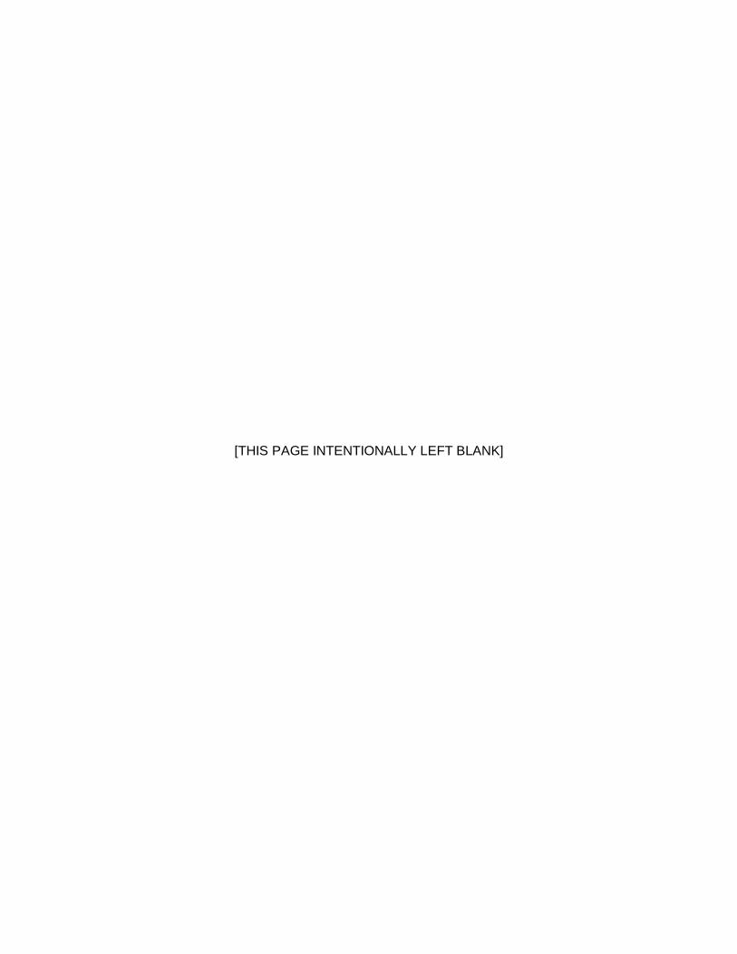
BRIDGE INSPECTION SUPPLEMENTAL REPORT Wisconsin Dept. of Transportation
DT2008 2010 (Replaces DT1906) s.84.17 Wis. Stats.
This form is an optional supplement and should be used to supply additional information on the condition of a bridge for Routine, Fracture Critical, In-Depth, Movable, Interim, Posted, Damage, UW-Visual, and UW-Probe inspections. Multiple supplemental forms may used. Condition Location, Description and Structure Notes Structure Number: _____________________
Condition Pictures and/or Sketches
Page _____ of _____

Instructions Bridge Inspection Supplemental Report
DT2008 • Condition Location and Description/Structure Notes – Notes used to further describe and clarify an element’s
condition and location. Comments already used in the condition states descriptions of the Pocket Manual should not be repeated. All notes should be preceded by the element number to which they apply. Existing notes will often be added to, and existing notes which no longer accurately describe the element may be crossed off or updated.
• Structure Number – The number assigned by the governing WisDOT Region Office that uniquely identifies a structure
for the inventory database. • Condition Pictures and/or Sketches – An area to attach inspection photos or to sketch figures that will clarify to the
reader element conditions or damage/deterioration locations on a bridge or culvert. • Page _____ of ______ - Fill in current and total number of pages included in this supplemental report.

Structure Inspection Manual Part 2 – Bridges Appendix B: Forms
March 2011 2-A-25
SECTION B.4 BRIDGE IN-DEPTH INSPECTION REPORT (DT2009)
Structure Inspection Manual Part 2 – Bridges Appendix B: Forms
March 2011 2-A-26
[THIS PAGE INTENTIONALLY LEFT BLANK]

Page 1 of 2
BRIDGE IN-DEPTH INSPECTION REPORT Wisconsin Dept. of Transportation
DT2009 2010 s.84.17 Wis. Stats.
This form is required as a supplement to DT2007, for In-Depth Inspections. A written report containing similar information may be substituted.
Structure Number: ____________________
List AASHTO Fatigue Detail Type 1. 3. 2. 4. Inspection Documentation
Component General Location
Specific Location Inspection Comments
Conclusion Comments Recommendations

Page 2 of 2
Instructions Bridge In-Depth Inspection Report
DT2009
• Structure Number - The number assigned by the governing WisDOT Region Office that uniquely identifies a structure for the inventory database.
• Component - The item being inspected, as indicated on the original design drawings, such as “pin and
hanger assembly”, etc.
• General Location – The span or girder inspected in terms of direction, such as “span 3” or “south girder”.
• Specific Location - The panel point or panel number being inspected as indicated on the original design drawings, etc.
• Inspection Comments – Report the inspection findings at each location. If no problems were noted, indicate
this as “OK” to indicate that the location was, in fact, inspected.
• Conclusion – Report the conclusions reached after reviewing findings and comments.
• Recommendations – Provide repair and inspection recommendations.
• List AASHTO Fatigue Detail - A general description of the fatigue prone detail.
Structure Inspection Manual Part 2 – Bridges Appendix B: Forms
March 2011 2-A-29
SECTION B.5 BRIDGE FRACTURE CRITICAL INSPECTION REPORT (DT2010)

Structure Inspection Manual Part 2 – Bridges Appendix B: Forms
March 2011 2-A-30
[THIS PAGE INTENTIONALLY LEFT BLANK]

Page 1 of 2
BRIDGE FRACTURE CRITICAL INSPECTION REPORT Wisconsin Department of Transportation
DT2010 2010 (Replaces DT1273) s.84.17 Wis. Stats.
This form is required as a supplement to form DT2007, for Fracture Critical Inspections.
Structure Number: _____________________ List AASHTO Fatigue Detail Type 1. 3. 2. 4.
Inspection Documentation
Component General Location
Specific Location Inspection Comments
Conclusion Comments Recommendations
Page 2 of 2
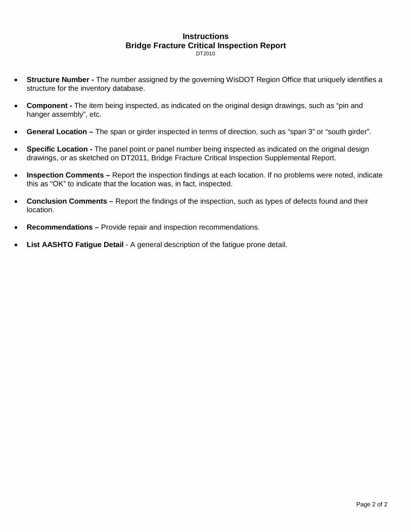
Instructions Bridge Fracture Critical Inspection Report
DT2010
• Structure Number - The number assigned by the governing WisDOT Region Office that uniquely identifies a structure for the inventory database.
• Component - The item being inspected, as indicated on the original design drawings, such as “pin and
hanger assembly”, etc.
• General Location – The span or girder inspected in terms of direction, such as “span 3” or “south girder”.
• Specific Location - The panel point or panel number being inspected as indicated on the original design drawings, or as sketched on DT2011, Bridge Fracture Critical Inspection Supplemental Report.
• Inspection Comments – Report the inspection findings at each location. If no problems were noted, indicate
this as “OK” to indicate that the location was, in fact, inspected.
• Conclusion Comments – Report the findings of the inspection, such as types of defects found and their location.
• Recommendations – Provide repair and inspection recommendations.
• List AASHTO Fatigue Detail - A general description of the fatigue prone detail.

Structure Inspection Manual Part 2 – Bridges Appendix B: Forms
March 2011 2-A-33
SECTION B.6 BRIDGE FRACTURE CRITICAL INSPECTION SUPPLEMENTAL REPORT (DT2011)

Structure Inspection Manual Part 2 – Bridges Appendix B: Forms
March 2011 2-A-34
[THIS PAGE INTENTIONALLY LEFT BLANK]

BRIDGE FRACTURE CRITICAL INSPECTION SUPPLEMENTAL REPORT Wisconsin Department of Transportation
DT2011 2010 s.84.17 Wis. Stats. This form is required as a supplement to form DT2007 for Fracture Critical Inspections. Use this form to provide a drawing or plan identifying fracture critical and non-fracture critical tension members. Diagram or Plan Structure Number: ___________________
Page ________ of __________

Instructions Bridge Fracture Critical Inspection Supplemental Report
DT2011
• Structure Number - The number assigned by the governing WisDOT Region Office that uniquely identifies a structure for the inventory database.
• Diagram or Plan Showing Fracture Critical Members – A hand sketched or copied plan of the bridge used to indicate the location of fracture critical members or components. A design or shop plan designating fracture critical members and non-fracture critical tension members may be attached in lieu of this form. Note: Include a Key for Fracture Critical Elements – Hatching placed over the structure diagram indicating which members are fracture critical. On trusses, the tension cord and tension diagonals and verticals are fracture critical members. On girders, the tension flange is a fracture critical element. Typically use Fracture Critical (xxx) Non-Fracture Critical Tension Members (ooo).
• Page ____ of _____ - Fill in current and total number of pages included in this supplemental report.

Structure Inspection Manual Part 2 – Bridges Appendix B: Forms
March 2011 2-A-37
SECTION B.7 STREAMBED PROFILE INSPECTION REPORT (DT2012)

Structure Inspection Manual Part 2 – Bridges Appendix B: Forms
March 2011 2-A-38
[THIS PAGE INTENTIONALLY LEFT BLANK]

Page 1 of 2
STREAMBED PROFILE INSPECTION REPORT Wisconsin Department of Transportation
DT2012 2010 s.84.17 Wis. Stats. Structure Number ______________________ General Sounding Equipment Vertical Control Date
Leadline Distance to Known Elevation
Location
Fathometer Known Elevation
County
Sounding Pole Waterline Elevation
Municipality
Description of Known Elevation
Streambed Elevation
Upstream Downstream Location 200’ 100’ Fascia Fascia 100’ 200’

Page 2 of 2
STREAMBED PROFILE REPORT
Structure Number ______________________ General Sounding Equipment Vertical Control Date
Leadline Distance to Known Elevation
Location
Fathometer Known Elevation
County
Sounding Pole Waterline Elevation
Municipality
Description of Known Elevation
Water Depths
Upstream Downstream Location 200’ 100’ Fascia Fascia 100’ 200’

Structure Inspection Manual Part 2 – Bridges Appendix B: Forms
March 2011 2-A-41
SECTION B.8 UNDERWATER BRIDGE INSPECTION – DIVE LOG (DT2013)

Structure Inspection Manual Part 2 – Bridges Appendix B: Forms
March 2011 2-A-42
[THIS PAGE INTENTIONALLY LEFT BLANK]
Page 1 of 1
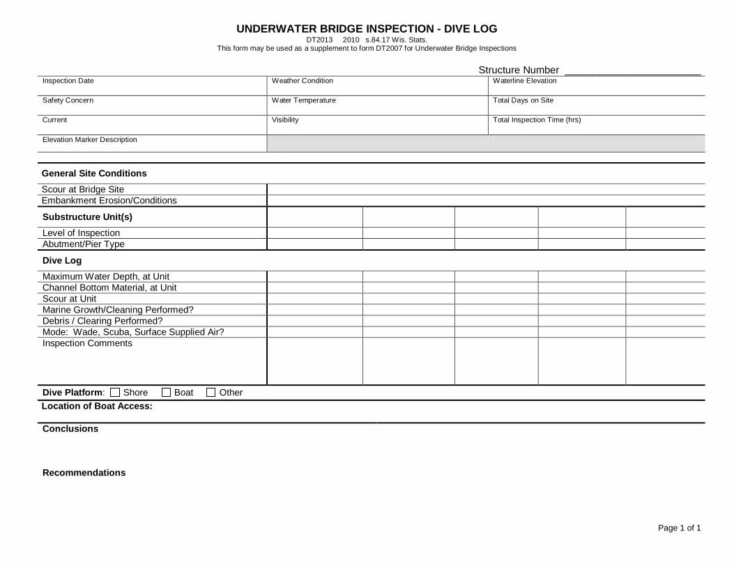
UNDERWATER BRIDGE INSPECTION - DIVE LOG DT2013 2010 s.84.17 Wis. Stats.
This form may be used as a supplement to form DT2007 for Underwater Bridge Inspections
Structure Number ________________________ Inspection Date
Weather Condition Waterline Elevation
Safety Concern
Water Temperature Total Days on Site
Current
Visibility Total Inspection Time (hrs)
Elevation Marker Description
General Site Conditions
Scour at Bridge Site Embankment Erosion/Conditions
Substructure Unit(s) Level of Inspection Abutment/Pier Type
Dive Log
Maximum Water Depth, at Unit Channel Bottom Material, at Unit Scour at Unit Marine Growth/Cleaning Performed? Debris / Clearing Performed? Mode: Wade, Scuba, Surface Supplied Air? Inspection Comments
Dive Platform: Shore Boat Other Location of Boat Access: Conclusions
Recommendations

[THIS PAGE INTENTIONALLY LEFT BLANK]

Structure Inspection Manual Part 2 – Bridges Appendix C: Fatigue Prone Details
March 2011 2-A-45
APPENDIX C: FATIGUE PRONE DETAILS
General Conditions Situation Kind of Stress
Stress Category
Illustrative Example (See Pgs 1-D-5 & 6)
Plain Member Base metal with rolled or cleaned surface. Flame-cut edges with ANSI smoothness of 1,000 or less.
T or Reva A 1,2
Built-Up Members Base metal and weld metal in members of built-up plates or shapes (without attachments) connected by continuous full penetration groove welds (with backing bars removed) or by continuous fillet welds parallel to the direction of applied stress.
T or Rev B 3,4,5,7
Base metal and weld metal in members of built-up plates or shapes (without attachments) connected by continuous full penetration groove welds with backing bars not removed, or by continuous partial penetration groove welds parallel to the direction of applied stress.
T or Rev B’ 3,4,5,7
Calculated flexural stress at the toe of transverse stiffener welds on girder webs or flanges.
T or Rev C 6
Base metal at ends of partial length welded coverplates with high-strength bolted slip-critical end connections (see Noteb)
T or Rev B 22
Base metal at ends of partial length welded coverplates narrower than the flange having square or tapered ends, with or without welds across the ends, or wider than the flange without welds across the ends.
(a) Flange thickness ≤ 0.8 in. (b) Flange thickness > 0.8 in.
T or Rev T or Rev
E E’
7 7
Base metal at ends of partial length welded coverplates wider than the flange without welds across the ends.
T or Rev E’ 7
Groove Welded Connections
Base metal and weld metal in or adjacent to full penetration groove weld splices of rolled or welded sections having similar profiles when welds are ground flush with grinding in the direction of applied stress and weld soundness established by nondestructive inspection.
T or Rev B 8,10
Base metal and weld metal in or adjacent to full penetration groove weld splices with 2-foot radius transitions in width, when welds are ground flush with grinding in the direction of applied stress and weld soundness established nondestructive inspection.
T or Rev B 13
Base metal and weld metal in or adjacent to full penetration groove weld splices at transitions in width or thickness, with welds ground to provide slopes no steeper than 1 to 2½, with grinding in the direction of the applied stress, and weld soundness

Structure Inspection Manual Part 2 – Bridges Appendix C: Fatigue Prone Details
March 2011 2-A-46
established by nondestructive inspection:
(a) AASTHO M 270 Grades 100/100W (ASTM A 709) base metal (b) Other base metals
T or Rev T or Rev
B’ B
11,12 11,12
Base metal and weld metal in or adjacent to full penetration groove weld splices, with or without transitions having slopes no greater than 1 to 2½, when the reinforcement is not removed and weld soundness is established by nondestructive inspection.
T or Rev C 8,10,11, 12
Groove Welded Attachments—Longitudinally Loadedc
Base metal adjacent to details attached by full or partial penetration groove welds when the detail length, L, in the direction of stress, is less than 2 inches.
T or Rev C 6.15
Base metal adjacent to details attached by full or partial penetration groove welds when the detail length, L, in the direction of stress, is between 2 inches and 12 times the plate thickness, but less than 4 inches.
T or Rev D 15
Base metal adjacent to details attached by full or partial penetration groove welds when the detail length, L, in the direction of stress, is greater than 12 times the plate thickness or greater than 4 inches:
(a) Detail thickness < 1.0 in. (b) Detail thickness ≥ 1.0 in.
T or Rev T or Rev
E E’
15 15
Base metal adjacent to details attached by full or partial penetration groove welds with a transition radius, R, regardless of the detail length:
--With the end welds ground smooth (a) Transition radius ≥ 24 in. (b) 24 in. > Transition radius ≥ 6 in. (c) 6 in. > Transition radius ≥ 2 in. (d) 2 in. > Transition radius ≥ 0 in.
T or Rev B C D E
16
--For all transition radii without end welds ground smooth.
T or Rev E 16
Groove Welded Attachments—Transversely Loadedc,d
Detail base metal attached by full penetration groove welds with a transition radius, R, regardless of the detail length and with weld soundness transverse to the direction of stress established by nondestructive inspection:
--With equal plate thickness and reinforcement removed (a) Transition radius ≥ 24 in. (b) 24 inc. > Transition radius > 6 in. (c) 6 in. > Transition radius ≥ 2 in. (d) 2 in. > Transition radius ≥ 0 in.
T or Rev B C D E
16
--With equal plate thickness and reinforcement not removed (a) Transition radius ≥ 6 in.
T or Rev C
16

Structure Inspection Manual Part 2 – Bridges Appendix C: Fatigue Prone Details
March 2011 2-A-47
(b) 6 in. > Transition radius ≥ 2 in. (c) 2 in. > Transition radius ≥ 0 in.
D E
--With unequal plate thickness and reinforcement removed (a) Transition radius ≥ 2 in. (b) 2 in. > Transition radius ≥ 0 in.
T or Rev D E
16
--For all transition radii with unequal plate thickness and reinforcement not removed.
T or Rev E 16
Fillet Welded Connections
Base metal at details connected with transversely loaded welds, with the welds perpendicular to the direction of stress:
(a) Detail thickness ≤ 0.5 in. (b) Detail thickness > 0.5 in.
T or Rev T or Rev
C See Notee
14
Base metal at intermittent fillet welds.
T or Rev E --
Shear stress on throat of fillet welds.
Shear F 9
Fillet Welded Attachments—Longitudinally Loaded
Base metal adjacent to details by fillet welds with length, L, in the direction of stress, is less than 2 inches and stud-type shear connectors.
T or Rev C 15,17,18,20
Base metal adjacent to details attached by fillet welds with length, L, in the direction of stress, between 2 inches and 12 times the plate thickness but less than 4 inches.
T or Rev D 15,17
Base metal adjacent to details attached by fillet welds with length, L, in the direction of stress, greater than 12 times the plate thickness or greater than 4 inches.
(a) Detail thickness < 1.0 in. (b) Detail thickness ≥ 1.0 in.
T or Rev T or Rev
E E’
7,9,15,17 7,9,15
Base metal adjacent to details attached by fillet welds with a transition radius, R, regardless of the detail length:
--With the end welds ground smooth (a) Transition radius ≥ 2 in. (b) 2 in. > Transition radius ≥ 0 in.
T or Rev D E
16
--For all transition radii without the end welds ground smooth.
T or Rev E 16
Fillet Welded Attachments—Transversely Loaded with the Weld in the Direction of Principal Stress
Detail base metal attached by fillet welds with a transition radius, R, regardless of the detail length (shear stress on the throat of fillet welds governed by Category F): --With the end welds ground smooth (a) Transition radius ≥ 2 in. (b) 2 in. > Transition radius ≥ 0 in.
T or Rev
D E
16
--For all transition radii without the end welds ground smooth.
T or Rev E 16

Structure Inspection Manual Part 2 – Bridges Appendix C: Fatigue Prone Details
March 2011 2-A-48
Mechanically Fastened Connections
Base metal at gross section of high-strength bolted slip-resistant connections, except at axially loaded joints which induce out-of-plane bending in connecting materials.
T or Rev B 21
Base metal at net section of high-strength bolted bearing-type connections.
T or Rev B 21
Base metal at net section of riveted connections.
T or Rev D 21
Eyebar or Pin Plates
Base metal at the net section of eyebar head or pin plate
T E 23,24
Base metal in the shank of eyebars, or through the gross section of pin plates with: (a) rolled or smoothly ground surfaces (b) flame-cut edges
T T
A B
23,24 23,24
a “T” signifies range in tensile stress only. “Rev” signifies a range of stress involving both tension and compression during a stress cycle.
b See Watter, Albrecht and Sahli, Journal of Structural Engineering, ASCE, Vol. III, No. 6, June 1985, pp. 1235-1249.
c “Longitudinally Loaded” signifies direction of approved stress is parallel to the longitudinal axis of the weld. “Tranversely Loaded” signifies direction of applied stress is perpendicular to the longitudinal axis of the weld.
d Transversely loaded partial penetration groove welds are prohibited.
e Allowable fatigue stress range on throat of fillet welds transversely loaded is a function of the effective throat and plate thickness. (See Frank and Fisher, Journal of the Structural Division, ASCE, Vo. 105, No. ST9, Sept. 1979).
f Gusset plates attached to girder flange surfaces with only transverse fillet welds are prohibited.

Structure Inspection Manual Part 2 – Bridges Appendix C: Fatigue Prone Details
March 2011 2-A-49

Structure Inspection Manual Part 2 – Bridges Appendix C: Fatigue Prone Details
March 2011 2-A-50

Structure Inspection Manual Part 2 – Bridges Appendix D: State Measurement Conventions
March 2011 2-A-51
APPENDIX D: STATE MEASUREMENT CONVENTIONS
SECTION D.1 GIRDER MEASUREMENT CONVENTIONS
The “number of girders” for a bridge as carried in the management database can be determined using one of the following examples. The total quantity recorded is equal to the girder length multiplied by the number of girders.

Structure Inspection Manual Part 2 – Bridges Appendix D: State Measurement Conventions
March 2011 2-A-52

Structure Inspection Manual Part 2 – Bridges Appendix D: State Measurement Conventions
March 2011 2-A-53
Figure D-1: On old reinforced concrete deck girders with large overhangs, the rail will act as a girder if it is a solid rail.

Structure Inspection Manual Part 2 – Bridges Appendix D: State Measurement Conventions
March 2011 2-A-54
SECTION D.2 TRUSS MEASUREMENT CONVENTIONS
All measurements of a truss are along the horizontal projection, including the deterioration measurements. The total length of the above truss is 50 feet, while the recorded length of the deteriorated part of the truss is equal to 8 feet (5 feet + 3 feet).
The total quantity for the truss element for the above example bridge is 100 feet (50 * 2, since there is a truss on each side of the bridge).
The convention used for spandrel arches is similar to that used for trusses.

Structure Inspection Manual Part 2 – Bridges Appendix D: State Measurement Conventions
March 2011 2-A-55
SECTION D.3 DECK MEASUREMENT CONVENTIONS
The unit for deck or slab elements is “square feet”. Thus, when a bridge has one deck/slab type, the quantity is the deck area. However, when a bridge has two different types of deck/slab elements (See the example below with Elements 113 and 39), the inspector should record a quantity equal to the deck area for each deck type element. The entire quantity for each deck or slab element is assigned to a single Condition State.
Element No. Description Quantity Unit
113 Concrete Deck (AC) 6,000 SF
39 Concrete Slab (AC) 4,000 SF
(Assumes a 100 foot long structure)

Structure Inspection Manual Part 2 – Bridges Appendix D: State Measurement Conventions
March 2011 2-A-56
SECTION D.4 ABUTMENT AND WINGWALL LENGTH MEASUREMENT CONVENTIONS
WING (EACH)
WING (EACH)
WING (EACH)
WING (EACH)
WING (EACH)

Structure Inspection Manual Part 2 – Bridges Appendix E: Fracture Critical Details
March 2011 2-A-57
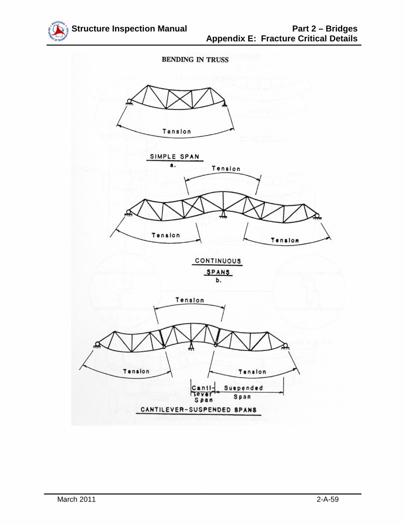
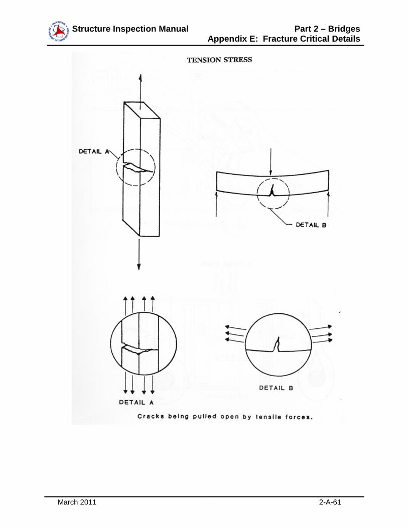
APPENDIX E: FRACTURE CRITICAL DETAILS

Structure Inspection Manual Part 2 – Bridges Appendix E: Fracture Critical Details
March 2011 2-A-58
Structure Inspection Manual Part 2 – Bridges Appendix E: Fracture Critical Details
March 2011 2-A-59

Structure Inspection Manual Part 2 – Bridges Appendix E: Fracture Critical Details
March 2011 2-A-60
Structure Inspection Manual Part 2 – Bridges Appendix E: Fracture Critical Details
March 2011 2-A-61

Structure Inspection Manual Part 2 – Bridges Appendix E: Fracture Critical Details
March 2011 2-A-62
Fatigue Categories A, B (on eyebar body), or E (on net section of eyebar head)

Structure Inspection Manual Part 2 – Bridges Appendix E: Fracture Critical Details
March 2011 2-A-63
Fatigue Category A, B (on hanger plate body), or E (on net section of hanger or pin plate)

Structure Inspection Manual Part 2 – Bridges Appendix E: Fracture Critical Details
March 2011 2-A-64
Fatigue Categories E and E’

Structure Inspection Manual Part 2 – Bridges Appendix E: Fracture Critical Details
March 2011 2-A-65
Web Out-of-Plane Bending at Floor Beam Connection Plate
Fatigue Tension

Structure Inspection Manual Part 2 – Bridges Appendix E: Fracture Critical Details
March 2011 2-A-66
Fatigue Category
Fatigue Category

Structure Inspection Manual Part 2 – Bridges Appendix E: Fracture Critical Details
March 2011 2-A-67
Fatigue Category
Fatigue Category E
Tension Flange

Structure Inspection Manual Part 2 – Bridges Appendix E: Fracture Critical Details
March 2011 2-A-68
[THIS PAGE INTENTIONALLY LEFT BLANK]


![WisDOT Bridge Manual Chapter 36 – Box Culvertson.dot.wi.gov/dtid_bos/extranet/structures/LRFD/BridgeManual/Ch-36.… · LRFD [5.7.1] 36.2.2 Bridge or Culvert Occasionally, the waterway](https://img.dokumen.tips/doc/110x75/5a78b28c7f8b9a21538c127b/wisdot-bridge-manual-chapter-36-box-lrfd-571-3622-bridge-or-culvert.jpg)