Embed Size (px)
Citation preview
Structural Design of a Building
Pedro Oliveira Gonçalves de Almeida Machado
Extended Abstract
October 2010


ABBREVEVIATIONS LIST
LATIN CAPITAL LETTERS
A – Area
�� – Total cross-sectional área of a concrete section
�� – Eurocode
��� – Instituto Superior Técnico
� – Design value of the applied internal bending moment
� � – Design value of the resistant axial force (tension or compression)
�� – Design value of the applied axial force (tension or compression)
� – Prestressing force
����� – Pre-stressed and Reinforced Concrete Structures Regulation
��� – Buildings and Bridges Structures Safety and Action Regulation
�� – Design value of resistant effects
�� – Design value of action effects
��� – Serviceability Limit States
��� – Ultimate Limit States
� � – Design value of the resistant shear force
�� – Design value of the applied shear force
LOWERCASE LATIN LETTERS
� – Overall width of a cross-section
�� – Width of the web on T, I or L beams
� – Effective depth of a cross-section
��� – Design value of concrete cylinder compressive strength
� – Overall depth of a cross-section
� – Length; Span
� – Crack width

LOWERCASE GREEK LETTERS
� – Seismicity coefficient
� – Performance coefficient
�� – Design applied stress
�� – Design resistant stress
– Damping coefficient

1
STRUCTURAL DESIGN OF A BUILDING
EXTENDED ABSTRACT
This thesis presents the development of a building’s structural design, based on an architectural
project. The scope of this work is to create a structural solution that ensures the safety of the building
when facing regulatory actions.
The purposed study object has a very irregular geometry, both in plan and in its height development.
With an implantation area of approximately 975m2, the building has 39.50m in its major extent.
Featuring one underground floor and three more other above ground floor with different plan
developments, its plan configuration shortens from floor to floor, until the top floor (2nd floor) shows a
corresponding area of 33% of the ground floor area.
Image 1 – Architectural project’s 1st floor plan
Image 2 – Architectural project’s West elevation
Since in this work is used the theoretical knowledge platform gained over the IST’s Structural
Engineering course, its goal is to understand the applicability of this platform to the practical activity of
structural design. Therefore, the different phases of a building’s structural design, from its initial
conception to the final design, are presented.
The first step of a building’s structural design is the resolution of a Structural Solution with quality and
economically viable that, according to its architecture, guarantees the safety of the building, its comfort
of use and a proper functioning. It consists of choosing the location, size and arrangement of different
structural elements, respecting the architectural project. The structural solution of the building in study
consists of a grid of columns (that unloads on standalone foundations) composed by three main
alignments. Slabs have a pre-stressed light weighted waffle slab with chapiters and solid bands due to
large spans (nearly 10m of span) presented in architectural project. The roof slab is a pre-stressed
massive slab with beams and the lower floor is surrounded by a earth retaining wall.
4.10
2.70
2.50
0.90
2.00
5.40
2.30
2.70
1.80
4.50
1.80
3.60
1.930.10
0.10
2.100.10
1.930.20
2.00
1.90
0.15
0.601.60
0.40
17.20
0.40
0.30
13.140.30
6.00 6.24 1.60 6.32 0.92 3.600.50
1.80 0.50 3.60 2.92
34.00
4.27
0.202.10
0.20
6.27
0.400.40
8.57
4.950.25
2.000.25
6.270.40
1. 80
7. 25
1. 75
2 .36
0.40
2.70
4.60
2.59
0.20
6.06
0.40
0.70
0.20
0.15
2.20
5. 50
0. 10
4.40
0. 40
0.40
10. 00
0. 40
0.40
1.40
3.50
5.10
4.10
0.20
7.01
0.20
0.40
28.95
1.47
1.80
0.40
1.80
1.14
1.50 0.15
2.45
0.20
2.06
10.84
0.90
0. 10
0.90
0.10
0.90
9.88
0.15
1.50
0.20
1.80
1.98
0.25
1.20
1. 50
0.10
1.20
0.10
1. 50
1.30
10.80
5.00
3 .70
0.30
0.40
6.04
35.60
10.52
6.72
3.25
1. 40
0.20
C
D
A
B
4.60
1.00
a.
d. c.
a.
c.
h.
g.
b. c.
h.
b.
i.
g.
c.
b.
c.
f.
c. c.
h.g.
f.i.
b.
b.b.
j.
e. e. e.

2
Image 3 – Column’s grid Image 4 –Light weighted waffle slab geometry
Safety Verification Criteria to Ultimate Limit States (ULS) and Serviceability Limit States (SLS) rules
recommended in the Portuguese and European structures regulation, namely RSA, REBAP and
Eurocodes, where adopted in the structure’s analysis and design.
ULS are related to the collapse, or any other form of structural break, which determines the inability to
use the structure. Their verification’s principle determines the following condition:
�� ! �� (1)
In section’s resistance calculus the following hypothesis were considered: the inexistence of
concrete’s tensile strength capacity, plane sections after deformation and a perfect bond between
rebar and concrete. The concrete and rebar design diagram extensions are limited to:
• Concrete’s shortening extension: 3.5 ‰
• Rebar’s elongation extension: 10.0 ‰
Image 5 – Limits to section’s extensions
SLS correspond to the structure’s impossibility of a normal use, being related to its durability,
appearance, user comfort and its correct functionality concerning users and also equipments and
possible existing machines. Their verification considers cracking and strain limit states as well as
stress verification.
In reinforced concrete elements, cracking occurs when concrete’s tensile strength (which is admitted
as null) is reach. Its consideration is related to the type of structure and its purpose. For current
buildings, excessive concrete’s cracking can cause, besides aesthetic problems, structure

3
deterioration due to rebar corrosion. Depending on the type of environment, crack’s maximum opening
was limited to � ) 0.3** for the frequent combination. Reached this maximum specified value,
durability and correct functionality of the concrete element is in jeopardy.
Strain limit state sets the maximum acceptable strain in order to guaranty structure’s normal use.
Strain should be controlled in order not to compromise structure, machinery or equipment functioning
and the integrity of non-structural elements such as partition walls, windows or even the coatings and
finishes.
Stress verification of the foundations was performed for the characteristic combination of actions,
based on the following condition:
�� + �� (2)
Structural analysis must consider the influence of all actions that might produce significant stress or
strain to the structure’s security. Depending on their variability in time and probability of occurrence,
actions can be classified as permanent actions, variables actions, or accidental actions. Permanent
and variables actions considered are quantified from the values listed in RSA. In the permanent
actions range are listed the self weights of the structural elements and masonry walls, the remaining
permanent loads related to coatings, finishes and earth pressures. In the variable actions range are
listed overloads, depending on the type of usage, and seismic action.
3.0 ,�/*.
4.0 ,�/*.
1.0 ,�/*.
2.0 ,�/*.
5.0 ,�/*.
Image 6 – Overloads in 1st floor
For the seismic action, a seismicity coefficient value of � ) 1.0 was considered, corresponding to
Portugal’s area A. As the building’s structural solution does not fit directly into any type of structure
recommended in REBAP (frame, wall or mixed), an elastic analysis of the structure’s deformed shape
was needed to determine the performance coefficient to use, which resulted in � ) 1.75. The response
spectra used were those recommended in RSA for type 1 and type 2 seism correspondent to type I
terrain and with a damping coefficient of ) 5%.
Seismic action type 1
Seismic action type 2
Graph 1 – Considered response spectra

4
A load is defined by the combination of actions that have non-negligible probability of acting
simultaneously on the structure, during a predetermined period of time. These combinations should
cover the different possibilities of load’s simultaneous occurrence in a plausible way, determining the
most critical effects on the structure. In accordance with the recommendations in RSA, it was
considered different combinations for the analysis of the ULS and ELS.
The materials adopted were C25/30 for concrete, A400 NR for ordinary rebar and A1600/1800 for pre-
stressed rebar. Rebar cover was considered to be 3cm. According to the available report of the
geological and geotechnical study of the work site, the terrain’s design stress resistance was
considered equal to 600 kPa.
After the structural solution is finalized, it is necessary to pre-design the structural elements in order to
determine the dimensions that satisfy the required safety conditions.
Slabs were pre-design considering a ratio of “slab thickness / span” corresponding to 3
4) 30. The
large deformation that this type of slab presents (larger than the upper limit of 1.50cm on long term)
led to the choice of a pre-stressed light weighted waffle slab.
Beam’s pre-design was based on the condition that the value for “beam height / span” must be
between 3
56 and
3
5.. With the estimated beams height obtained, the next procedure is a simple
verification of the following safety conditions for ULS:
7 )8�
� 9 �. 9 ���+ 0.25 (3)
�8� + 0.5 9 � � : 0.5 9 ;. 9 �� 9 � (4)
These values were calculated according to the following beam’s influence areas:
Image 7 – 1st floor beam’s influence areas
Column’s pre-design has a highly important role in structural design initial phase, since these are the
elements that most interfere in architectural environments. Following REBAP’s article 144º, the area
required for each column to resist axial force can be obtained by the following expression:
�� <��
0.6 9 ��� (5)
5
The axial forced unloaded into each column was based on the following column´s influence areas:
Image 8 –2nd floor column’s influence areas
To pre-design standalone foundations it was ensured that the terrain was able to withstand the
transmitted stresses. Knowing the axial force at the base of the columns, the minimum area of
standalone foundations was determined by the following expression:
�>?@ <��A3B>@
�C�> (6)
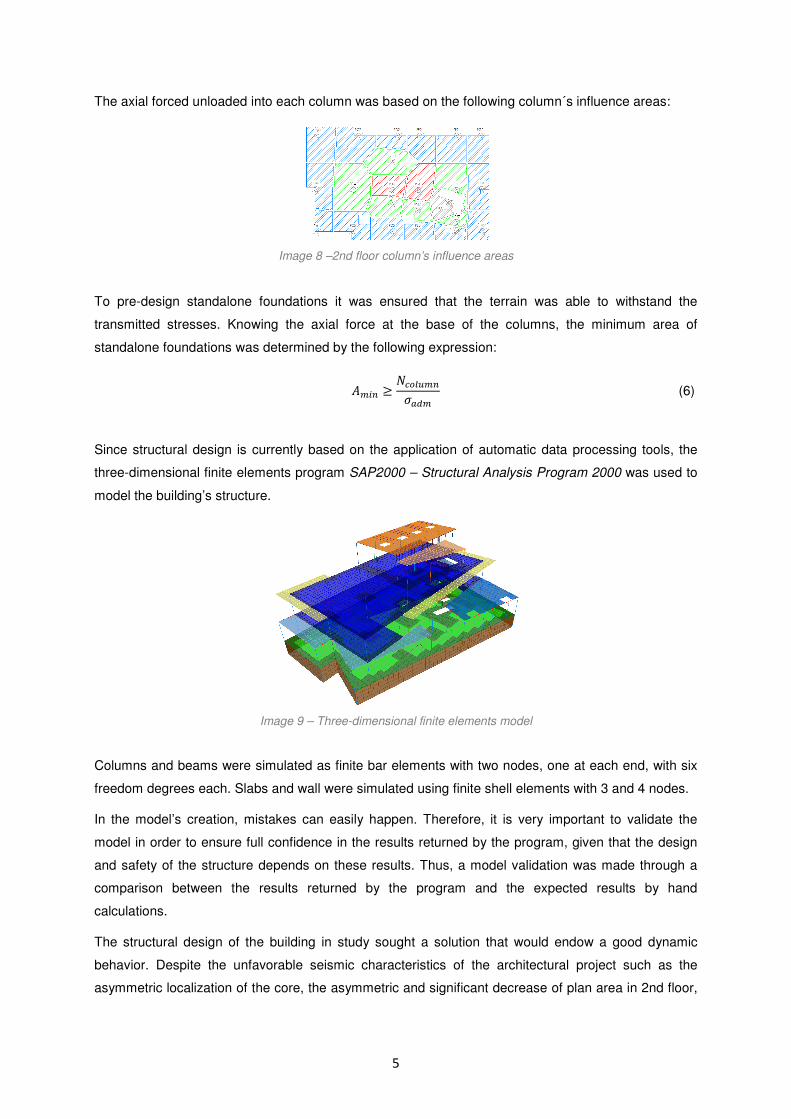
Since structural design is currently based on the application of automatic data processing tools, the
three-dimensional finite elements program SAP2000 – Structural Analysis Program 2000 was used to
model the building’s structure.
Image 9 – Three-dimensional finite elements model
Columns and beams were simulated as finite bar elements with two nodes, one at each end, with six
freedom degrees each. Slabs and wall were simulated using finite shell elements with 3 and 4 nodes.
In the model’s creation, mistakes can easily happen. Therefore, it is very important to validate the
model in order to ensure full confidence in the results returned by the program, given that the design
and safety of the structure depends on these results. Thus, a model validation was made through a
comparison between the results returned by the program and the expected results by hand
calculations.
The structural design of the building in study sought a solution that would endow a good dynamic
behavior. Despite the unfavorable seismic characteristics of the architectural project such as the
asymmetric localization of the core, the asymmetric and significant decrease of plan area in 2nd floor,

6
among others, the solution provides an acceptable seismic behavior. The frequencies, mass
participation factors and vibration modes are listed below:
Periods, Frequencies and Mass Participation Factors
Mode Period [s] Frequencie [Hz] Ux Uy sum Ux sum Uy Rz sum Rz
1 0.48 2.08 23.2% 19.6% 23.2% 19.6% 0.2% 0.2%
2 0.40 2.50 12.7% 46.5% 35.9% 66.2% 54.5% 54.7%
3 0.32 3.13 34.5% 0.0% 70.5% 66.2% 0.0% 54.7%
10 0.13 7.69 4.5% 0.1% 88.7% 81.9% 0.1% 68.8%
Image 10 – 3d view of 1st vibration mode
Image 11 – 3d view of 2nd vibration mode
Image 12 – 3d view of 3rd vibration mode
The seismic coefficient was calculated by the following expression presented in RSA’s Article 31º:
D )EF
EG (7)
A structure or part of it, reaches a limit state when, in an effective or convention method, it becomes
unusable or ceases to satisfy the conditions for its use. Therefore, when a structure fails to meet these
conditions, it is reaching a limit state, which can be of structural (ULS) or functional (SLS) nature.
ULS verification consists in verifying the load capacity of elements to deal with the actions that they
are subject to. Throughout the corresponding chapter, verifications to guaranty the safety of elements
subject to simple bending, compound bending, bi-axial bending, shear and punching are explained.
SLS are those states which correspond to the impossibility of normal use of a structure. Cracking and
strain limit states are verified.
Image 13 – Material’s extent limits Image 14 – Diagram zones associated to rupture

A post-processing program that verifies
rebar subject to compound bending
compound bending in one direction, was developed. Image 14 shows the 5 different zones associate
to rupture considered in the program
Programmed in Visual Basic programming language through
follows the following procedure:
Thus, elements subject to compound
results are returned in an A4 sheet
materials, section‘s dimensions, rebar and rebar percentage,
values, design resistant effects and the
Compound Bending
Compound Bending Effects
• Concrete class
• Rebar type
• Section dimension
• Rebar number and Φ
• Iteration number
Data
Introduction
• Section extents
determination
• Stress calculation
• Resistant axial force and
moment calculation
-7000
-6000
-5000
-4000
-3000
-2000
-1000
0
1000
2000
-800
NR
d[k
N]
Program's N
7
that verifies the safety of rectangular cross-sections with symmetrical
bending in both directions and also “H” or “T” cross
one direction, was developed. Image 14 shows the 5 different zones associate
considered in the program, depending on material’s extent limits presented in EC2.
programming language through Microsoft Office Excel
pound bending, were designed using the developed
sheet which features section’s characteristics, including
imensions, rebar and rebar percentage, maximum and minimum
effects and the NRd - MRd interaction diagram above.
Compound Bending Effects – 0º direction
Interaction diagram –
Compound Bending Effects – 90º direction
Interaction diagram – 9
Section extents
determination
Stress calculation
Resistant axial force and
moment calculation
Concrete
Calculation • Rebar extents
determination
• Stress calculation
• Resistant axial force and
moment calculation
Rebar
Calculation
• Sum of resistant effects for
each rupture diagram
• Resistant section graph
draw
-600 -400 -200 0 200 400 600
MRd [kN.m]
Program's NRd - MRd Interaction Diagrams in two directions
sections with symmetrical
in both directions and also “H” or “T” cross-sections subject to
one direction, was developed. Image 14 shows the 5 different zones associate
, depending on material’s extent limits presented in EC2.
Microsoft Office Excel, the program
developed program whose
, including considered
minimum NRd and MRd
0º direction
90º direction
Sum of resistant effects for
each rupture diagram
Resistant section graph
draw
Graph Drawing
800
Interaction Diagrams in two directions

8
Nowadays, the application of pre-stressed slabs is a competitive solution in common structures,
representing an economic and efficient solution. Its application can reduce slab’s thickness and,
consequently, its own weight, resulting on the reduction of the structure is overall weight and allows
the construction of larger spans. The solution adopted is composed by post-tensioned non adherent
mono-strands. Since these slabs consist of a recoverable waffle slab formwork blocks solution, its
configuration limits mono-strands number to 2 per rib.
Image 15 – Pre-stressed strands distribution in ground floor
Image 16 – Pre-stressed strands distribution in 1st floor
Image 17 – Pre-stressed strands distribution in roof’s slab
Image 18 – Schematic pre-stressed cable trace, with green pulling loads and blue equivalent punctual loads
The equivalent punctual loads were calculated using the following expression:
Pre-stressed solutions are divided into two distinct techniques, pre-tensioned and post-tensioned,
being the latest one subdivided into adherent and non adherent cables. Post-tensioned pre-stress is
applied after the concrete has acquired sufficient strength, being stress transfer assured by anchorage
in the extreme ends of the piece. Compared to other systems, non adherent pre-stress has, among
others, the following advantages: for thinner slabs the adoption of mono-strands allows to conduct
better eccentricity; flexible strands allows a simple cable tracing (trapezoidal) for easy placement and
also adaptable to complex geometries; no need for injection and allows adjustment at any instant of
life of the structure.
Once established a structural solution with a three-dimensional static and dynamic analysis realized,
and considering safety criteria listed, as well as calculation hypotheses to verify, building’s structure
elements such as columns, core, slabs and beams are designed. Results of this design are presented
PP
M=Pxfsup
fsupfinf
fsup
Ptan
Ptan Ptan
Ptan
PP
M=Pxfsup
H ) �IJKL�M (8)

9
in Appendix, such as pre-stress drawings, reinforced concrete drawings and global structure drawings.
Some of these drawings are showed below:
Image 19 – 1st floor plan Image 20 – 2nd floor plan
Image 21 – 2nd floor slab’s inferior side reinforced concrete
Image 22 – Beam’s reinforced concrete
2 mono-cordõespor nervura (tipo 2)
2 mono-cordõespor nervura (tipo 2)
2 mono-cordõespor nervura (tipo 1)
2 mono-cordõespor nervura (tipo 2)
2 mono-cordõespor nervura (tipo 1)
mono-cordões afast.200mm (tipo 1)

10
Image 23 – Core’s reinforced concrete Image 24 – Column’s reinforced
concrete
Throughout the work was tested the knowledge acquired along the course of Structural Engineering,
which allowed an analysis of all different types of structural elements, although not all were completely
designed.
Comparing pre-design values to the model’s results, it is conclusive that results associated to columns
were proved similar. As to beams, these values were not so close even though they allowed to obtain
reasonable results. In fact, this initial analysis is of high importance, since it allows to obtain a
reasonable idea of initial dimensions required for structural elements.
As for the structure’s dynamic behavior, considering its irregular geometry both in plan and in its
height development, this has proved difficult to interpret, particularly vibration mode analysis, where
modal participation factors led to a different expected dynamic behavior from what observed in the
overall structure deformed shape. This happens because the building's geometry leads to a seismic
behavior hard to predict.
Concrete cross section verification to compound bending program developed turned out to be very
useful, since it allows an automatic verification of a significant number of columns, walls and core, and
also the determination of resistant bending moment for pre-stressed slabs.
Keywords: Structural Design; Bending with Axial Force; Pre-Design; Modeling; Seismic Analysis;
Design.

11
BIBLIOGRAPHY
Camacho, J. S.; Concreto Armado: Estados Limites de Utilização; Ilha Solteira; Faculdade de
Engenharia de Ilha Solteira; 2005.
Camposinhos, Rui de Sousa; Lajes Pré-Esforçadas por Cabos Não Aderentes; Porto; Faculdade de
Engenharia da Universidade do Porto; 1991.
Freitas, Fernanda; Flexão Composta; FCTUC; 2007/2008.
Marchão, Carla e Appleton, Júlio; Introdução ao Comportamento das Estruturas de Betão Armado;
Lisboa; Instituto Superior Técnico; 2008/2009.
Marchão, Carla e Appleton, Júlio; Verificação da Segurança aos Estados Limites Últimos de
Elementos com Esforço Axial Desprezável; Lisboa; Instituto Superior Técnico; 2008/2009.
Marchão, Carla e Appleton, Júlio; Verificação do Comportamento em Serviço (Estados Limites se
Utilização – SLS); Lisboa; Instituto Superior Técnico; 2008/2009.
Marchão, Carla e Appleton, Júlio; Verificação da Segurança aos Estados Limites Últimos de
Elementos com Esforço Axial Não Desprezável; Lisboa; Instituto Superior Técnico; 2008/2009.
Marchão, Carla e Appleton, Júlio; Pré-Esforço; Lisboa; Instituto Superior Técnico; 2007/2008.
Marchão, Carla e Appleton, Júlio; Lajes de Betão Armado; Lisboa; Instituto Superior Técnico;
2007/2008.
Marchão, Carla e Appleton, Júlio; Fundações de Edifícios; Lisboa; Instituto Superior Técnico;
2007/2008.
Martins, João Guerra; Acção dos Sismos; 2009.
Martins, João Guerra; Pilares em Betão Armado; 2003.
Santos, Álvaro; Martins, João Guerra; Fundamentos de Betão Pré-Esforçado; 2006.
Eurcódigo 2 – Projecto de Estruturas de Betão, Parte 1-1: Regras Gerais e Regras para Edifícios;
LNEC; 2010.
Eurcódigo 7 – Projecto Geotécnico: Regras Gerais; LNEC; 2010.
Eurcódigo 8 – Projecto de Estruturas para Resistência aos Sismos, Parte 1:Regras Gerais, Acções
Sísmica e Regras para Edifícios; LNEC; 2010.
R.S.A. – Regulamento de Segurança e Acções para Estruturas de Edifícios e Pontes; Porto; Porto
Editora; 1983.
R.E.B.A.P. – Regulamento de Estruturas de Betão Armado e Pré-Esforçado; Porto; Porto Editora;
1983.