Embed Size (px)
Citation preview
Winter 2012 | PCI Journal110
The performance of a structure is mainly linked to its strength, stiffness, and ductility, although function-ality, aesthetics, speed of construction, and econo-
my are also significant.
The following functional requirements should be taken into consideration:
• Long spans with floor space uninterrupted by columns or structural walls give users maximum flexibility.
• A maximum floor-to-floor height allows adequate spaces and a reduced overall building height.
• Open-space apartments or offices (adaptable floors) can accommodate future tenant alterations with maxi-mum speed and minimum disruption or cost.
It is well known that the economic performance of a struc-tural system greatly depends on the quantities of materi-als per square meter (for example, concrete, reinforcing bars, and strands), but the real construction cost can also depend on speed of construction, local market conditions, availability of labor and specialized equipment, and other factors.
■ A new all–precast concrete system was used in Romania to construct a residential building.
■ To validate the quality and performance of this type of structure, an extensive program of theoretical analyses and structural tests (including shake table tests) was conducted.
■ Due to its functional and technical advantages, high productiv-ity, and low cost, the building system has been used in more than 500 flats in Transylvania, Romania.
Structural behavior of an innovative all–precast concrete dual system for residential buildings
Adrian M. Ioani and Eusebiu Tripa
111PCI Journal | Winter 2012
Flat-slab structures in seismic zones
Performance characteristics related to building functional-ity, aesthetics, and economy can be encountered in the case of structures made of slabs and columns, the so-called typi-cal flat-slab structures. These structures carry vertical and lateral forces and achieve their lateral stability by frame action generated by the interaction of columns and slabs.
In many cases, such as multistory buildings or structures in seismic areas, pure flat-slab structures have to be altered by the addition of vertical elements, such as shear walls or steel bracing systems, leading to dual systems. The equiva-lent frames, comprising slabs and columns, mainly ensure the transfer of gravity loads and a portion of the seismic loads, while the structural wall system provides the lateral resistance and stiffness of the building1 so that such a dual structure can be successfully used even in areas with high seismic activity.
To improve the competitiveness of such a structure type and considering constructability as a powerful tool for re-ducing the cost and the time of construction, the designers’ interest has focused on a standard precast concrete struc-ture using fewer elements with standard dimensions that can be produced in large numbers on an industrial basis.
Objectives
In an attempt to solve the difficult problem of the con-struction of residential buildings in Romania, taking into consideration the previously mentioned factors and require-ments, a design team from the Design Institute of Hunedo-ara in Romania, led by Eusebiu Tripa, proposed a new all–precast concrete system of a dual flat-slab structure type.
A complex program, including theoretical studies and many experimental tests,2 preceded the national-scale promotion of this system. Academics from Romanian civil engineering faculties in Jassy, Cluj, Timis̹oara, and Bucharest; researchers from INCERC-Bucharest (National Building Research Institute) and from the INCERC depart-ments of Timis̹oara, Jassy, and Cluj; architects; and civil engineers participated in this program.
This paper presents the main characteristics of the new build-ing system, the principal features of the experimental program that preceded its launch on the market, and the conclusions concerning the structural performance of the system.
Precast concrete dual flat-slab structure
Structure characteristics
The structural system presented in this paper is dedicated to residential buildings with up to nine stories, and it
mainly consists of long precast concrete columns—a unit is from 5.40 m (18 ft) to 11.40 m (37.4 ft) long—and pre-cast concrete flat-slab panels with spans of 3.60 m (12 ft) to 6.00 m (20 ft).
The promotion of such a system in seismic areas was conditioned by the use of a limited number of structural walls in the structure, leading to a dual structural system of the frame-wall type (Fig. 1). Figure 2 shows this innova-tive precast concrete structure during erection in the city of Deva, Romania.
In Europe, Romania is considered to have a high level of seismic risk, where earthquakes over 7 on the Richter scale occur quite frequently. Bucharest is the most vulner-able capital in Europe.3 The seismic response to the accel-erograms recorded in Bucharest during the 1977 Vrancea earthquake (magnitude of earthquake on the moment magnitude scale Mw equal to 7.5 with 0.2g peak ground acceleration, where g is acceleration due to gravity) shows uncommonly high displacement demands. Extensive non-structural damage during this earthquake was reported due to large lateral displacements. For this reason, the Roma-nian Seismic Design Code P 100-924 limits the allowable interstory drift to 0.35% for buildings with infill walls interacting with the frame structure when the structure is checked in the serviceability limit state (SLS). The new Romanian Seismic Design Code P 100-1/20065 introduced a more relaxed value of 0.5% for allowable interstory drift for verifications in the SLS, comparable to that specified by FEMA 356/20006 for shear wall structures when imme-diate occupancy structural performance level is considered.
Precast concrete columns
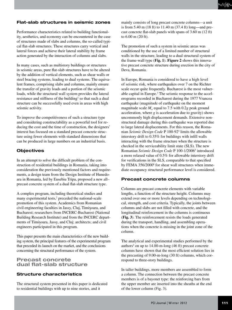
Columns are precast concrete elements with variable lengths, a function of the structure height. Columns may extend over one or more levels depending on technologi-cal, strength, and cost criteria. Typically, the joints between columns and slabs are not filled with concrete, and the longitudinal reinforcement in the columns is continuous (Fig. 3). The reinforcement resists the loads generated during the transport, handling, and assembling opera-tions when the concrete is missing in the joint zone of the column.
The analytical and experimental studies performed by the authors2 on up to 14.00-m-long (46 ft) precast concrete columns have shown that the most efficient solution lies in the precasting of 9.00-m-long (30 ft) columns, which cor-respond to three-story buildings.
In taller buildings, more members are assembled to form a column. The connection between the precast concrete members is of a bayonet type: the reinforcing bars from the upper member are inserted into the sheaths at the end of the lower column (Fig. 3).

Winter 2012 | PCI Journal112
Precast concrete floors
The floors are made of large precast concrete flat-slab pan-els supported at the corners by mechanical devices fixed on the columns.
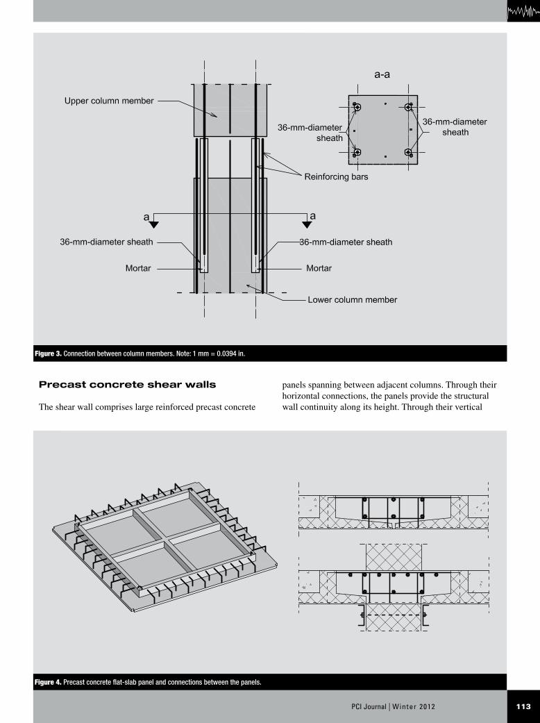
The spacing between the columns, usually ranging from 3.00 m (10 ft) to 6.00 m (20 ft), dictates the span of precast concrete slab panels; the floor panel is of the ribbed flat-slab type (Fig. 4). The continuity of the precast concrete floor is achieved by narrow cast-in-place concrete strips re-inforced by longitudinal bars and horizontal loops (Fig. 4).
Figure 1. Types of elements in the precast concrete dual flat-slab structure.
Figure 2. All–precast concrete dual structure during erection.
113PCI Journal | Winter 2012
panels spanning between adjacent columns. Through their horizontal connections, the panels provide the structural wall continuity along its height. Through their vertical
Precast concrete shear walls
The shear wall comprises large reinforced precast concrete
Figure 3. Connection between column members. Note: 1 mm = 0.0394 in.
Figure 4. Precast concrete flat-slab panel and connections between the panels.
Winter 2012 | PCI Journal114
between precast concrete members should be determined by analyses or by tests.”7
In addition, section 21.2.1.5 says that a precast concrete structural system “may be used for earthquake resistance if it is demonstrated by experimental evidence and analysis that the proposed system will have strength and toughness equal to or exceeding those provided by a comparable monolithic reinforced concrete structure.”7
To assess the structural quality and the performance of this structural system designed for seismic zones, the research team conducted an extensive analytical and experimental study. The research program2 included tests on column-to-column joints, experimental tests on a precast concrete structural wall subassemblage, postelastic computer analy-sis of precast concrete structural walls, tests on a full-scale assemblage of columns and precast concrete flat slabs subjected to gravity forces, shake table tests on a struc-ture prototype (scale 1:4), and in-place dynamic tests on a real five-story building. In this large scientific program, researchers from three universities and four institutes and structural designers from two design institutes were involved.
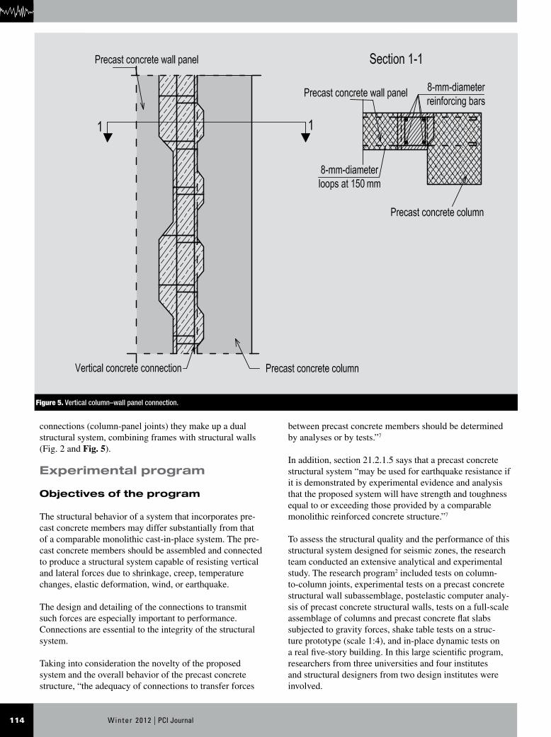
connections (column-panel joints) they make up a dual structural system, combining frames with structural walls (Fig. 2 and Fig. 5).
Experimental program
Objectives of the program
The structural behavior of a system that incorporates pre-cast concrete members may differ substantially from that of a comparable monolithic cast-in-place system. The pre-cast concrete members should be assembled and connected to produce a structural system capable of resisting vertical and lateral forces due to shrinkage, creep, temperature changes, elastic deformation, wind, or earthquake.
The design and detailing of the connections to transmit such forces are especially important to performance. Connections are essential to the integrity of the structural system.
Taking into consideration the novelty of the proposed system and the overall behavior of the precast concrete structure, “the adequacy of connections to transfer forces
Figure 5. Vertical column–wall panel connection.
115PCI Journal | Winter 2012
Flat-slab structure under gravity loads
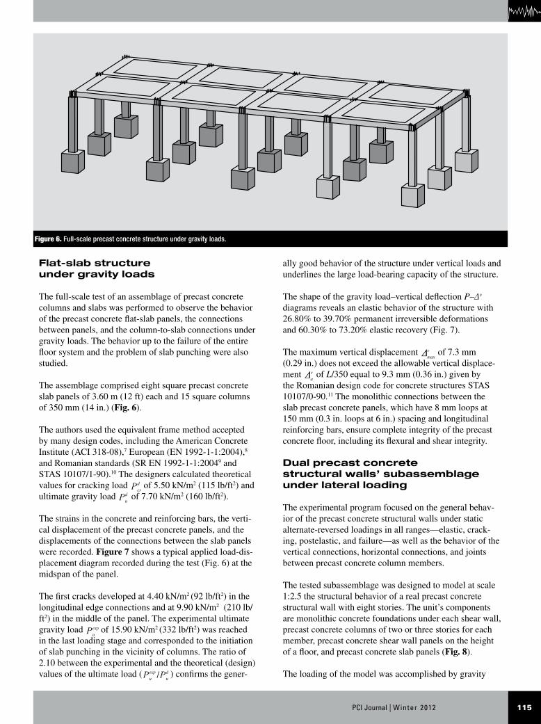
The full-scale test of an assemblage of precast concrete columns and slabs was performed to observe the behavior of the precast concrete flat-slab panels, the connections between panels, and the column-to-slab connections under gravity loads. The behavior up to the failure of the entire floor system and the problem of slab punching were also studied.
The assemblage comprised eight square precast concrete slab panels of 3.60 m (12 ft) each and 15 square columns of 350 mm (14 in.) (Fig. 6).
The authors used the equivalent frame method accepted by many design codes, including the American Concrete Institute (ACI 318-08),7 European (EN 1992-1-1:2004),8 and Romanian standards (SR EN 1992-1-1:20049 and STAS 10107/1-90).10 The designers calculated theoretical values for cracking load P
cr
d of 5.50 kN/m2 (115 lb/ft2) and ultimate gravity load P
u
d of 7.70 kN/m2 (160 lb/ft2).
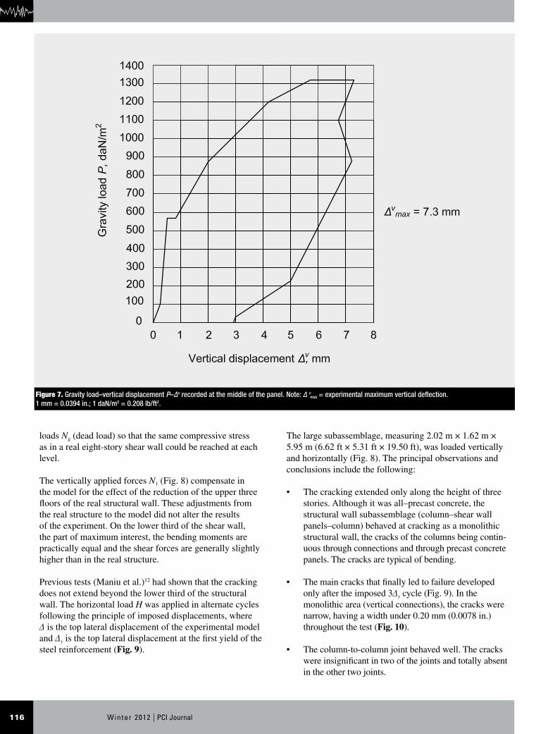
The strains in the concrete and reinforcing bars, the verti-cal displacement of the precast concrete panels, and the displacements of the connections between the slab panels were recorded. Figure 7 shows a typical applied load-dis-placement diagram recorded during the test (Fig. 6) at the midspan of the panel.
The first cracks developed at 4.40 kN/m2 (92 lb/ft2) in the longitudinal edge connections and at 9.90 kN/m2 (210 lb/ft2) in the middle of the panel. The experimental ultimate gravity load Pexp
u of 15.90 kN/m2 (332 lb/ft2) was reached
in the last loading stage and corresponded to the initiation of slab punching in the vicinity of columns. The ratio of 2.10 between the experimental and the theoretical (design) values of the ultimate load ( /P Pexp
u u
d ) confirms the gener-
ally good behavior of the structure under vertical loads and underlines the large load-bearing capacity of the structure.
The shape of the gravity load–vertical deflection P–Δv diagrams reveals an elastic behavior of the structure with 26.80% to 39.70% permanent irreversible deformations and 60.30% to 73.20% elastic recovery (Fig. 7).
The maximum vertical displacement max
vD of 7.3 mm (0.29 in.) does not exceed the allowable vertical displace-ment v
aD of L/350 equal to 9.3 mm (0.36 in.) given by
the Romanian design code for concrete structures STAS 10107/0-90.11 The monolithic connections between the slab precast concrete panels, which have 8 mm loops at 150 mm (0.3 in. loops at 6 in.) spacing and longitudinal reinforcing bars, ensure complete integrity of the precast concrete floor, including its flexural and shear integrity.
Dual precast concrete structural walls’ subassemblage under lateral loading
The experimental program focused on the general behav-ior of the precast concrete structural walls under static alternate-reversed loadings in all ranges—elastic, crack-ing, postelastic, and failure—as well as the behavior of the vertical connections, horizontal connections, and joints between precast concrete column members.
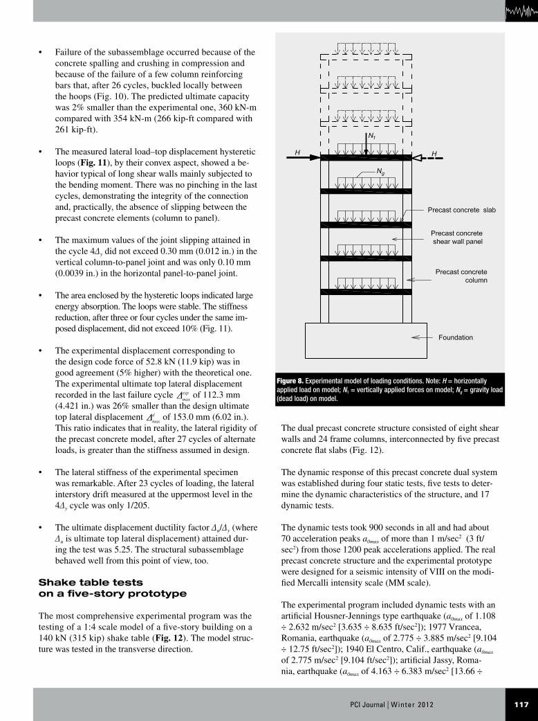
The tested subassemblage was designed to model at scale 1:2.5 the structural behavior of a real precast concrete structural wall with eight stories. The unit’s components are monolithic concrete foundations under each shear wall, precast concrete columns of two or three stories for each member, precast concrete shear wall panels on the height of a floor, and precast concrete slab panels (Fig. 8).
The loading of the model was accomplished by gravity
Figure 6. Full-scale precast concrete structure under gravity loads.
Winter 2012 | PCI Journal116
loads Ng (dead load) so that the same compressive stress as in a real eight-story shear wall could be reached at each level.
The vertically applied forces N1 (Fig. 8) compensate in the model for the effect of the reduction of the upper three floors of the real structural wall. These adjustments from the real structure to the model did not alter the results of the experiment. On the lower third of the shear wall, the part of maximum interest, the bending moments are practically equal and the shear forces are generally slightly higher than in the real structure.
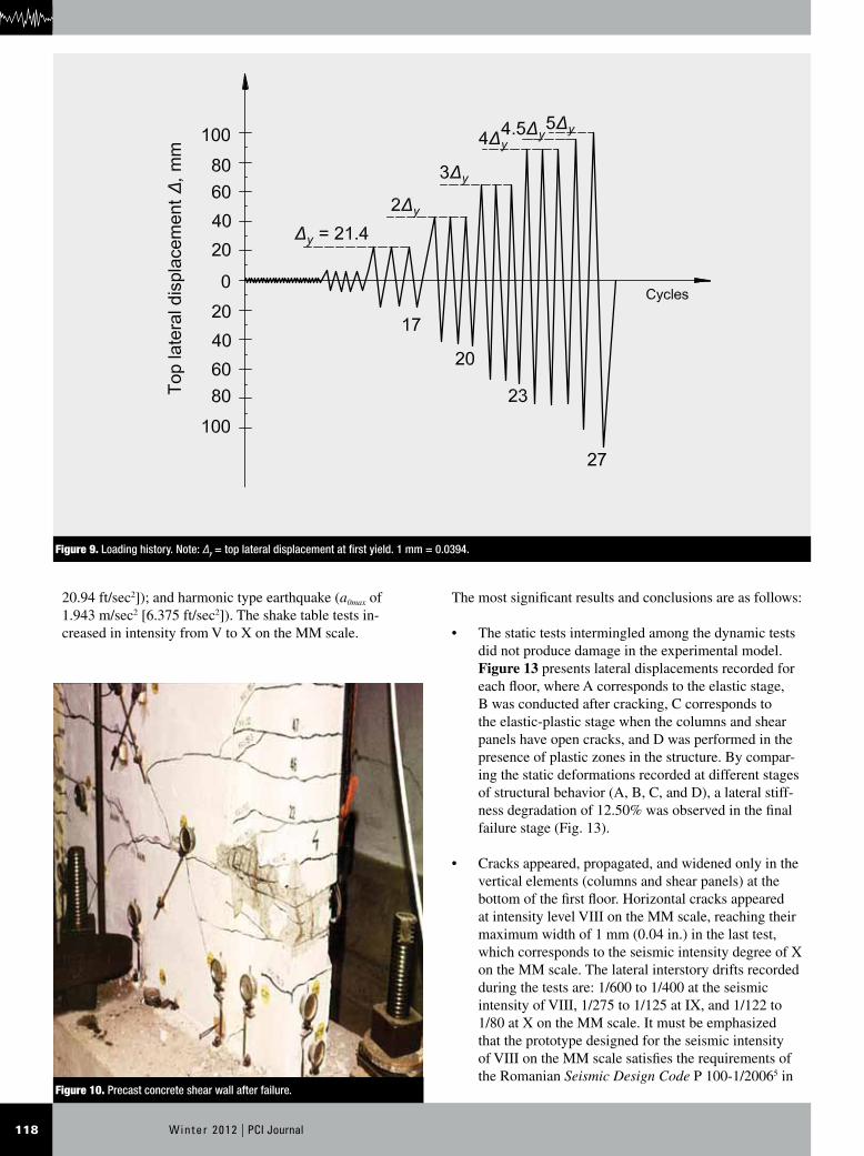
Previous tests (Maniu et al.)12 had shown that the cracking does not extend beyond the lower third of the structural wall. The horizontal load H was applied in alternate cycles following the principle of imposed displacements, where Δ is the top lateral displacement of the experimental model and Δy is the top lateral displacement at the first yield of the steel reinforcement (Fig. 9).
The large subassemblage, measuring 2.02 m × 1.62 m × 5.95 m (6.62 ft × 5.31 ft × 19.50 ft), was loaded vertically and horizontally (Fig. 8). The principal observations and conclusions include the following:
• The cracking extended only along the height of three stories. Although it was all–precast concrete, the structural wall subassemblage (column–shear wall panels–column) behaved at cracking as a monolithic structural wall, the cracks of the columns being contin-uous through connections and through precast concrete panels. The cracks are typical of bending.
• The main cracks that finally led to failure developed only after the imposed 3Δy cycle (Fig. 9). In the monolithic area (vertical connections), the cracks were narrow, having a width under 0.20 mm (0.0078 in.) throughout the test (Fig. 10).
• The column-to-column joint behaved well. The cracks were insignificant in two of the joints and totally absent in the other two joints.
Figure 7. Gravity load–vertical displacement P–Δv recorded at the middle of the panel. Note: Δ vmax = experimental maximum vertical deflection.
1 mm = 0.0394 in.; 1 daN/m2 = 0.208 lb/ft2.
117PCI Journal | Winter 2012
The dual precast concrete structure consisted of eight shear walls and 24 frame columns, interconnected by five precast concrete flat slabs (Fig. 12).
The dynamic response of this precast concrete dual system was established during four static tests, five tests to deter-mine the dynamic characteristics of the structure, and 17 dynamic tests.
The dynamic tests took 900 seconds in all and had about 70 acceleration peaks a0max of more than 1 m/sec2 (3 ft/sec2) from those 1200 peak accelerations applied. The real precast concrete structure and the experimental prototype were designed for a seismic intensity of VIII on the modi-fied Mercalli intensity scale (MM scale).
The experimental program included dynamic tests with an artificial Housner-Jennings type earthquake (a0max of 1.108 ÷ 2.632 m/sec2 [3.635 ÷ 8.635 ft/sec2]); 1977 Vrancea, Romania, earthquake (a0max of 2.775 ÷ 3.885 m/sec2 [9.104 ÷ 12.75 ft/sec2]); 1940 El Centro, Calif., earthquake (a0max of 2.775 m/sec2 [9.104 ft/sec2]); artificial Jassy, Roma-nia, earthquake (a0max of 4.163 ÷ 6.383 m/sec2 [13.66 ÷
• Failure of the subassemblage occurred because of the concrete spalling and crushing in compression and because of the failure of a few column reinforcing bars that, after 26 cycles, buckled locally between the hoops (Fig. 10). The predicted ultimate capacity was 2% smaller than the experimental one, 360 kN-m compared with 354 kN-m (266 kip-ft compared with 261 kip-ft).
• The measured lateral load–top displacement hysteretic loops (Fig. 11), by their convex aspect, showed a be-havior typical of long shear walls mainly subjected to the bending moment. There was no pinching in the last cycles, demonstrating the integrity of the connection and, practically, the absence of slipping between the precast concrete elements (column to panel).
• The maximum values of the joint slipping attained in the cycle 4Δy did not exceed 0.30 mm (0.012 in.) in the vertical column-to-panel joint and was only 0.10 mm (0.0039 in.) in the horizontal panel-to-panel joint.
• The area enclosed by the hysteretic loops indicated large energy absorption. The loops were stable. The stiffness reduction, after three or four cycles under the same im-posed displacement, did not exceed 10% (Fig. 11).
• The experimental displacement corresponding to the design code force of 52.8 kN (11.9 kip) was in good agreement (5% higher) with the theoretical one. The experimental ultimate top lateral displacement recorded in the last failure cycle
max
expD of 112.3 mm (4.421 in.) was 26% smaller than the design ultimate top lateral displacement
max
dD of 153.0 mm (6.02 in.). This ratio indicates that in reality, the lateral rigidity of the precast concrete model, after 27 cycles of alternate loads, is greater than the stiffness assumed in design.
• The lateral stiffness of the experimental specimen was remarkable. After 23 cycles of loading, the lateral interstory drift measured at the uppermost level in the 4Δy cycle was only 1/205.
• The ultimate displacement ductility factor Δu/Δy (where Δu is ultimate top lateral displacement) attained dur-ing the test was 5.25. The structural subassemblage behaved well from this point of view, too.
Shake table tests on a five-story prototype
The most comprehensive experimental program was the testing of a 1:4 scale model of a five-story building on a 140 kN (315 kip) shake table (Fig. 12). The model struc-ture was tested in the transverse direction.
Figure 8. Experimental model of loading conditions. Note: H = horizontally applied load on model; N1 = vertically applied forces on model; Ng = gravity load (dead load) on model.
Winter 2012 | PCI Journal118
The most significant results and conclusions are as follows:
• The static tests intermingled among the dynamic tests did not produce damage in the experimental model. Figure 13 presents lateral displacements recorded for each floor, where A corresponds to the elastic stage, B was conducted after cracking, C corresponds to the elastic-plastic stage when the columns and shear panels have open cracks, and D was performed in the presence of plastic zones in the structure. By compar-ing the static deformations recorded at different stages of structural behavior (A, B, C, and D), a lateral stiff-ness degradation of 12.50% was observed in the final failure stage (Fig. 13).
• Cracks appeared, propagated, and widened only in the vertical elements (columns and shear panels) at the bottom of the first floor. Horizontal cracks appeared at intensity level VIII on the MM scale, reaching their maximum width of 1 mm (0.04 in.) in the last test, which corresponds to the seismic intensity degree of X on the MM scale. The lateral interstory drifts recorded during the tests are: 1/600 to 1/400 at the seismic intensity of VIII, 1/275 to 1/125 at IX, and 1/122 to 1/80 at X on the MM scale. It must be emphasized that the prototype designed for the seismic intensity of VIII on the MM scale satisfies the requirements of the Romanian Seismic Design Code P 100-1/20065 in
20.94 ft/sec2]); and harmonic type earthquake (a0max of 1.943 m/sec2 [6.375 ft/sec2]). The shake table tests in-creased in intensity from V to X on the MM scale.
Figure 9. Loading history. Note: Δy = top lateral displacement at first yield. 1 mm = 0.0394.
Figure 10. Precast concrete shear wall after failure.

119PCI Journal | Winter 2012
the ultimate limit state, where the allowable interstory drift is 2.5%, even for earthquakes of X on the MM scale, where the measured maximum interstory drifts are of 0.82% to 1.25%.
• The tests to determine the dynamic characteristics within five different stages of structural behavior, from the elastic to the plastic stage, showed that the natural frequency of the model diminished from 6.50 Hz to 5.00 Hz in the transverse direction and from 6.00 Hz to 5.03 Hz in the longitudinal direction. At the same time, the critical damping ratio increased from 1.38 to 3.10 in the transverse direction and from 1.00 to 3.02 in the longitudinal direction. Despite reductions of fre-quency by 23% transversally, 16% longitudinally, and 29% in torsion, the stiffness degradation after a series of high-intensity seismic actions was only 12.50%, which shows that the structure can be consolidated and its structural integrity can be restored.
In-place dynamic test on a real structure
Working with experts from INCERC-Bucharest, the au-thors coordinated an in-place investigation to determine the dynamic characteristics of a real structure that has three
spans of 3.60 m (11.8 ft), ten bays of 3.90 m (12.8 ft), and five stories of 3.00 m (9.84 ft) high.
Comparisons have been made between the dynamic char-acteristics of a precast concrete structure comprising only structural columns, panels, and walls (the first stage) and
Figure 11. Lateral load–top lateral displacement envelope curves. Note: H = horizontal applied load on model; Δc = cracking displacement; Δy = top lateral displace-ment at first yield. 1 mm = 0.0394 in.; 1 kN = 0.225 kip.
Figure 12. Five-story precast concrete structure (model scale 1:4) during shake table tests.
Winter 2012 | PCI Journal120
those of the second testing stage, when the structure also had nonstructural walls (partitions) mounted.
A large volume of experimental data related to the struc-tural response under five different types of dynamic excita-tions was recorded, and detailed conclusions are presented in the author’s PhD thesis.2
The main observations are as follows:
• The nonstructural walls significantly increased the stiffness and damping capacity of the building. Thus, the natural period of vibration decreased from 0.63 sec to 0.32 sec in the longitudinal direction and from 0.40 sec to 0.32 sec in the transverse direction.
• The damping capacity of the building increased due to the contribution of nonstructural elements, and, conse-quently, the critical damping ratio increased from 0.01 to 0.05 in the horizontal longitudinal direction.
• The general torsion of the structure is beneficially in-fluenced when nonstructural elements are introduced; the structure becomes stiffer, and the natural period of vibration decreases significantly from 0.44 sec to 0.25 sec.
The natural periods of vibration in place determined on this new type of dual precast concrete structure are simi-
Figure 13. Lateral displacements–static horizontal load diagrams. Note: Test A corresponds to the elastic stage, test B was conducted after the cracking, test C corresponds to the elastic-plastic stage, and test D was performed in the pres-ence of plastic zones in the structure. F = static horizontal load = 6 kN. 1 mm = 0.0394 in.; 1 kN = 0.225 kip.
Figure 14. Residential condominiums
121PCI Journal | Winter 2012
hibited good behavior during the 1977 Vrancea earthquake (Mw of 7.5).
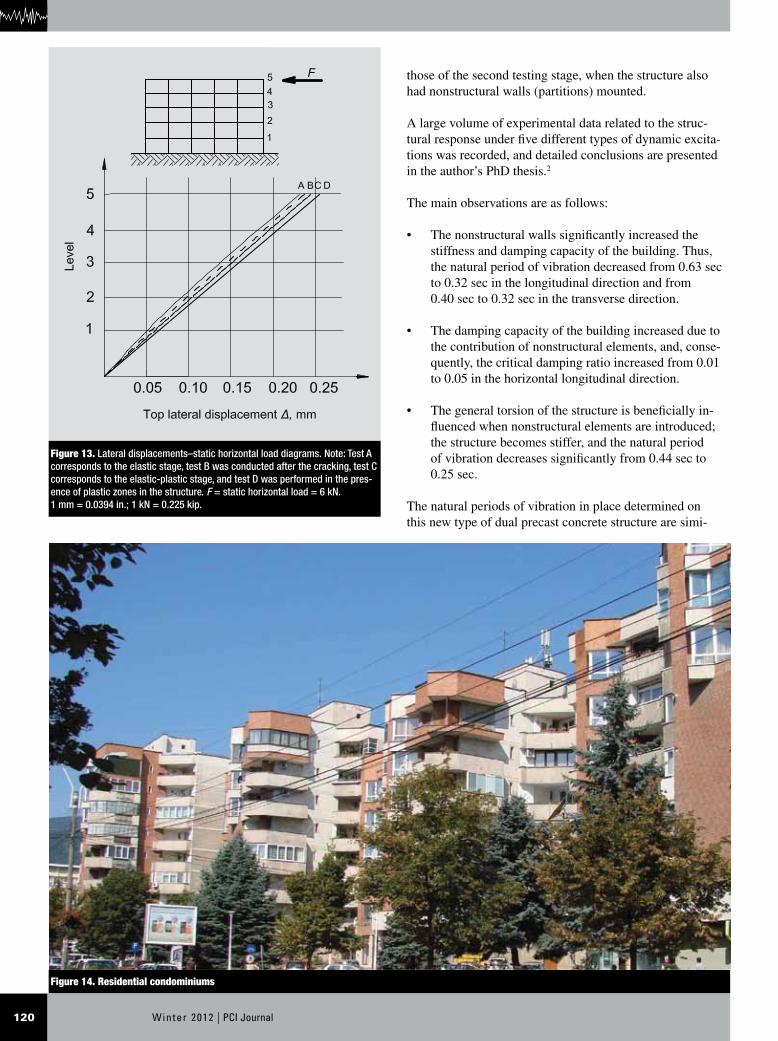
Due to its functional and technical advantages, high pro-ductivity, and low costs, the constructive system has been used in more than 500 flats in Transylvania, Romania. Three hundred apartments are in five- to nine-story build-ings (Fig. 14), and 200 are in residential condominiums that have to five stories.
References
1. Crainic, L. 2003. Reinforced Concrete Structure. Cluj-Napoca, Romania: Napoca Star.
2. Tripa, E. 2002. Contributions to the Study, Design and Erection of Buildings with Precast Concrete Mixed Structure. [In Romanian.] PhD thesis. University Po-litehnica from Timis̹oara (UPT), Timis̹oara, Romania.
3. Lungu, D., C. Arion, S. Demetriu, and A. Aldea. 2003. Probabilistic Zonation of Vrancea Seismic Hazard. Eurocode 8, Representation of Design Actions. In Pro-ceedings of the International Conference: Construc-tions 2003, July 16–17, 2003. Cluj-Napoca, Romania: Napoca Star and Argonaut.
4. Ministry of Public Works and Territory Management (MLPAT). 1992. Seismic Design Code (P100-92). [In Romanian.] Bucharest, Romania: MLPAT.
5. Ministry of Transportation, Construction and Tourism (MTCT). 2006. Seismic Design Code—Part I: Provi-sions for Buildings (P 100-1/2006). [In Romanian.] Bucharest, Romania: MTCT.
6. Federal Emergency Management Agency (FEMA). 2000. Prestandard and Commentary for the Seismic Rehabilitation of Buildings. FEMA 356. Washington, DC: FEMA.
7. American Concrete Institute (ACI) Committee 318. 2008. Building Code Requirements for Structural Concrete (ACI 318-08) and Commentary (ACI 318R-08). Farmington Hills, MI: ACI.
8. European Committee of Standardization (CEN). 2004. EN 1992-1-1: 2004. In Eurocode 2: Design of Con-crete Structures—Part 1-1: General Rules and Rules for Buildings. Brussels, Belgium: CEN.
9. Romanian Standards Association (ASRO). 2004. SR EN 1992-1-1: 2004. In Eurocode 2: Design of Con-crete Structures—Part 1-1: General Rules and Rules for Buildings. [In Romanian.] Bucharest, Romania: ASRO.
lar to the values determined in Bucharest on reinforced concrete frame structures with infill masonry panels; those structures exhibited good behavior during the March 4, 1977, Vrancea earthquake (Mw of 7.5).
Conclusion
In an attempt to solve the difficult problem of the construc-tion of residential buildings in Romania, the design team proposed a new all–precast concrete system of a dual flat-slab type.
To assess the quality and performance of this system, an extensive program of theoretical analyses, structural tests, and applied studies to improve the construction technology were conducted. These studies maximized the effect on construction productivity and minimized the total cost.
A full-scale test on an assemblage of precast concrete columns and precast concrete flat slabs confirms the gener-ally good behavior of the structure under gravity loads and underlines the large load-bearing capacity of the structure. The ratio between the experimental and the theoretical values of the ultimate load is 2.10.
The large subassemblage of two precast concrete, five-story structural walls; four precast concrete columns; and five precast concrete flat slabs was tested up to failure. The loading consisted of constant vertical forces and horizontal forces applied in alternate cycles following the principle of imposed displacements. The test on this model (scale 1:2.5) confirmed its structural performance with respect to the load-bearing capacity, stiffness, ductility, and cracking. The experimental values regarding the ultimate capacity and lateral displacements are in good agreement with the theo-retical ones. The hysteretic loops (H–Δ) are stable, and the prototype demonstrated a large energy absorption capacity.
The types of connections proved suitable, resulting in a behavior for the precast concrete subassemblage that was similar to that of the monolithic solution.
The dynamic tests carried out on the 140 kN (315 kip) shake table at INCERC-Jassy, where a five-story precast concrete structure (scale 1:4) was tested, showed that the lateral stiffness degradation of the structure was only 12.5% in the final failure stage. The tests took 900 seconds and had 70 acceleration peaks of more than 1 m/sec2
(3 ft/sec2). The interstory drifts recorded during the tests satisfy the requirements of the Romanian Seismic Design Code P 100-1/2006.5
In-place tests on a real structure erected in the city of Deva indicated that the natural periods of vibration of this new type of precast concrete structure are similar to the values determined in Bucharest on reinforced concrete frame structures with infill masonry panels. These structures ex-
Winter 2012 | PCI Journal122
Δv = vertical displacement (deflection)
v
aD = allowable vertical displacement (deflection) speci-
fied by design code
max
vD = experimental maximum vertical deflection
Δc = cracking displacement
Δu = ultimate top lateral displacement
Δu/Δy = displacement ductility factor
Δy = top lateral displacement at first yield
10. Romanian Standards Institute (IRS). 1990. Reinforced and Prestressed Concrete Floors. General Design Specifications. In Civil and Industrial Buildings. STAS 10107/1-90. [In Romanian.] Bucharest, Romania: IRS.
11. IRS. 1990. Design and Detailing of Concrete, Rein-forced and Prestressed Concrete Structural Members. In Civil and Industrial Buildings. STAS 10107/0-90. [In Romanian.] Bucharest, Romania: IRS.
12. Maniu, H., A. M. Ioani, and E. Tripa. 1992. Structural Investigation on a Seismic Performance of Precast Mixed Shear Walls. In Proceedings of the Tenth World Conference on Earthquake Engineering, Madrid, July 19–24, 1992. Rotterdam, Netherlands: Balkema.
Notation
a0max = maximum values of accelerations (acceleration peaks) applied during dynamic tests
F = static horizontal load applied during shake table tests
g = acceleration due to gravity = 9.81 m/sec2
(32.2 ft/sec2)
H = horizontal applied load on model
L = length (span) of precast concrete slab panels
Mw = magnitude of earthquake on the moment magnitude scale (MMS)
N1 = vertically applied forces on model
Ng = gravity load (dead load) on model
P = gravity load applied on the full-scale assemblage
Pcr
d = design (calculated) cracking load for the full-scale assemblage
Pu
d = design (calculated) ultimate gravity load for the full-scale assemblage
Pexpu
= experimental (measured) ultimate gravity load ap-plied on the full-scale assemblage
Δ = top lateral displacement
max
dD = design (calculated) maximum (ultimate) top lateral displacement
max
expD = experimental maximum (ultimate) top lateral dis-placement

123PCI Journal | Winter 2012
About the authors
Adrian M. Ioani, PhD, FACI, FAICPS-Romania, is a professor of structural mechanics at the Technical University of Cluj-Nap-oca in Romania and former director of INCERC-Cluj (National Building Research Institute).
Eusebiu Tripa, PhD, P.E., FA-ICPS-Romania, is a senior structural engineer at Tripexpert Design Office in Deva, Romania.
Abstract
This paper discusses a new all–precast concrete system used in Romania to construct a residential build-ing. Designed for constructability, a new all–precast concrete system comprising columns, flat slabs, and structural walls was proposed by the design team. To validate the structural quality and performance of this type of structure, an extensive program of theoretical
analyses and structural tests (including shake table tests) was conducted. The tests demonstrated good behav-ior of the precast concrete dual system (frame-wall) adapted for a classic flat-slab structure. The connections resulted in a similar behavior of the precast concrete system to that of the monolithic solution. Due to its functional and technical advantages, high productivity, and low cost, this system has been used in more than 500 flats in Transylvania, Romania.
Keywords
Connection, dual system, flat-slab panel, loading, seismic.
Review policy
This paper was reviewed in accordance with the Precast/Prestressed Concrete Institute’s peer-review process.
Reader comments
Please address any reader comments to journal@pci .org or Precast/Prestressed Concrete Institute, c/o PCI Journal, 200 W. Adams St., Suite 2100, Chicago, IL 60606. J