Embed Size (px)
Citation preview
Copyright 2012 AIA MasterSpec Premium 08/12
PRECAST ARCHITECTURAL CONCRETE 034500 - 1
SECTION 034500 - PRECAST ARCHITECTURAL CONCRETE
PART 1 - GENERAL
1.1 RELATED DOCUMENTS
A. Drawings and general provisions of the Contract, including General and Supplementary Conditions and Division 01 Specification Sections, apply to this Section.
1.2 SUMMARY
A. Section Includes:
1. Architectural precast concrete cladding [ and load-bearing] units. 2. Insulated, architectural precast concrete units. 3. Thin-brick-faced, architectural precast concrete units. 4. Stone-faced, architectural precast concrete units.
B. Related Requirements:
1. Section 033000 "Cast-in-Place Concrete" for installing connection anchors in concrete. 2. Section 034900 "Glass-Fiber-Reinforced Concrete (GFRC)." 3. Section 047200 "Cast Stone Masonry" for wet- or dry-cast cast stone facings, trim, and
accessories. 4. Section 051200 "Structural Steel Framing" for furnishing and installing connections
attached to structural-steel framing. 5. Section 055000 "Metal Fabrications" for kickers and other miscellaneous steel shapes. 6. Section 071900 "Water Repellents" for water-repellent finish treatments. 7. Section 085113 "Aluminum Windows" for windows set into architectural precast
concrete units.
1.3 ALLOWANCES
A. Thin brick is part of <Insert name of allowance>.
B. [Preconstruction] [Source quality-control] [and] [field quality-control] testing are part of testing and inspecting allowance.
1.4 DEFINITIONS
A. Design Reference Sample: Sample of approved architectural precast concrete color, finish and texture, preapproved by Architect.

Copyright 2012 AIA MasterSpec Premium 08/12
PRECAST ARCHITECTURAL CONCRETE 034500 - 2
1.5 PREINSTALLATION MEETINGS
A. Preinstallation Conference: Conduct conference at [Project site] <Insert location>.
1.6 ACTION SUBMITTALS
A. Product Data: For each type of product.
B. LEED Submittals:
1. Product Data for Credit MR 4: For products having recycled content, documentation indicating percentages by weight of postconsumer and preconsumer recycled content. Include statement indicating cost for each product having recycled content.
2. Product Certificates for Credit MR 5: For products and materials required to comply with requirements for regional materials, certificates indicating location of material manufacturer and point of extraction, harvest, or recovery for each raw material. Include statement indicating distance to Project, cost for each regional material, and fraction by weight that is considered regional.
C. Design Mixtures: For each precast concrete mixture. Include compressive strength and water-absorption tests.
D. Shop Drawings:
1. Detail fabrication and installation of architectural precast concrete units. 2. Indicate locations, plans, elevations, dimensions, shapes, and cross sections of each unit. 3. Indicate joints, reveals, drips, chamfers, and extent and location of each surface finish. 4. Indicate details at building corners. 5. Indicate separate face and backup mixture locations and thicknesses. 6. Indicate type, size, and length of welded connections by AWS standard symbols. Detail
loose and cast-in hardware and connections. 7. Indicate locations, tolerances, and details of anchorage devices to be embedded in or
attached to structure or other construction. 8. Indicate locations, extent, and treatment of dry joints if two-stage casting is proposed. 9. Include plans and elevations showing unit location and sequence of erection for special
conditions. 10. Indicate location of each architectural precast concrete unit by same identification mark
placed on panel. 11. Indicate relationship of architectural precast concrete units to adjacent materials. 12. Indicate locations, dimensions, and details of thin-brick units, including corner units and
special shapes, and joint treatment. 13. Indicate locations, dimensions, and details of stone facings, anchors, and joint widths. 14. If design modifications are proposed to meet performance requirements and field
conditions, submit design calculations and Shop Drawings. Do not adversely affect the appearance, durability, or strength of units when modifying details or materials and maintain the general design concept.
E. Samples: Design reference samples for initial verification of design intent, for each type of finish indicated on exposed surfaces of architectural precast concrete units, in sets of three,
Copyright 2012 AIA MasterSpec Premium 08/12
PRECAST ARCHITECTURAL CONCRETE 034500 - 3
representative of finish, color, and texture variations expected; approximately 12 by 12 by 2 inches (300 by 300 by 50 mm).
1. When other faces of precast concrete unit are exposed, include Samples illustrating workmanship, color, and texture of backup concrete as well as facing concrete.
2. Samples for each thin-brick unit required, showing full range of color and texture expected. Include Sample showing color and texture of joint treatment.
a. Grout Samples for Initial Selection: Color charts consisting of actual sections of grout showing manufacturer's full range of colors.
b. Grout Samples for Verification: Showing color and texture of joint treatment.
F. Delegated-Design Submittal: For architectural precast concrete indicated to comply with performance requirements and design criteria, including analysis data signed and sealed by the qualified professional engineer responsible for their preparation.
1. Show governing panel types, connections, types of reinforcement, including special reinforcement, and concrete cover on reinforcement. Indicate location, type, magnitude, and direction of loads imposed on the building structural frame from architectural precast concrete.
1.7 INFORMATIONAL SUBMITTALS
A. Qualification Data: For [Installer] [fabricator] [testing agency].
B. Welding certificates.
C. Material Certificates: For the following items:
1. Cementitious materials. 2. Reinforcing materials and prestressing tendons. 3. Admixtures. 4. Bearing pads. 5. Structural-steel shapes and hollow structural sections. 6. Thin-brick units and accessories. 7. Stone anchors. 8. Insulation.
D. Material Test Reports: For aggregates.
E. Preconstruction test reports.
F. Source quality-control test reports.
G. Field quality-control[ and special inspection] reports.
Copyright 2012 AIA MasterSpec Premium 08/12
PRECAST ARCHITECTURAL CONCRETE 034500 - 4
1.8 QUALITY ASSURANCE
A. Installer Qualifications: A precast concrete erector qualified and designated by PCI's Certificate of Compliance to erect [Category A (Architectural Systems) for non-load] [Category S2 (Complex Structural Systems) for load]-bearing members.
B. Installer Qualifications: A precast concrete erector who has retained a "PCI-Certified Field Auditor" to conduct a field audit of a project in same category as this Project and who can produce an Erectors' Post-Audit Declaration.
C. Fabricator Qualifications: A firm that assumes responsibility for engineering architectural precast concrete units to comply with performance requirements. This responsibility includes preparation of Shop Drawings and comprehensive engineering analysis by a qualified professional engineer.
1. Designated as a PCI-certified plant for Group A, Category A1 - Architectural Cladding and Load Bearing Units[ at time of bidding][ or designated as an APA-certified plant for production of architectural precast concrete products].
2. Fabricator is located within 500 miles (800 km) of Project site.
D. Testing Agency Qualifications: An independent testing agency[, acceptable to authorities having jurisdiction,] qualified according to ASTM C 1077 and ASTM E 329 for testing indicated.
E. Quality-Control Standard: For manufacturing procedures and testing requirements, quality-control recommendations, and dimensional tolerances for types of units required, comply with PCI MNL 117, "Manual for Quality Control for Plants and Production of Architectural Precast Concrete Products."
F. Welding Qualifications: Qualify procedures and personnel according to AWS D1.1/D.1.1M, "Structural Welding Code - Steel"; and AWS D1.4/D1.4M, "Structural Welding Code - Reinforcing Steel."
G. Sample Panels: After sample approval and before fabricating architectural precast concrete units, produce a minimum of [two] <Insert number> sample panels approximately [16 sq. ft. (1.5 sq. m)] <Insert dimension> in area for review by Architect. Incorporate full-scale details of architectural features, finishes, textures, and transitions in sample panels.
1. Locate panels where indicated or, if not indicated, as directed by Architect. 2. Damage part of an exposed-face surface for each finish, color, and texture, and
demonstrate adequacy of repair techniques proposed for repair of surface blemishes. 3. After acceptance of repair technique, maintain one sample panel at manufacturer's plant
and one at Project site in an undisturbed condition as a standard for judging the completed Work.
4. Demolish and remove sample panels when directed.
H. Range Samples: After sample panel approval and before fabricating architectural precast concrete units, produce a minimum of [three] [five] <Insert number> sets of samples, approximately [16 sq. ft. (1.5 sq. m)] <Insert dimension> in area, representing anticipated range of each color and texture on Project's units. Maintain one set of range samples at Project
Copyright 2012 AIA MasterSpec Premium 08/12
PRECAST ARCHITECTURAL CONCRETE 034500 - 5
site and remaining range sample sets at manufacturer's plant as color and texture approval reference.
I. Mockups: After sample panel[ and range sample] approval but before production of architectural precast concrete units, construct full-sized mockups to verify selections made under Sample submittals and to demonstrate aesthetic effects and to set quality standards for materials and execution.
1. Build mockup as indicated on Drawings including [aluminum framing, glass, sealants,] <Insert construction> and architectural precast concrete complete with anchors, connections, flashings, and joint fillers.
2. Approval of mockups does not constitute approval of deviations from the Contract Documents contained in mockups unless Architect specifically approves such deviations in writing.
3. Subject to compliance with requirements, approved mockups may become part of the completed Work if undamaged at time of Substantial Completion.
J. Preconstruction Testing Mockup: Provide a full-size mockup of architectural precast concrete indicated on Drawings for preconstruction testing. See Section <Insert Section number> "<Insert Section title>" for preconstruction testing requirements.
1. Build preconstruction testing mockup as indicated on Drawings including [aluminum framing, glass, sealants,] <Insert construction> and architectural precast concrete complete with anchors, connections, flashings, and joint fillers.
2. Build preconstruction testing mockup at testing agency facility.
1.9 PRECONSTRUCTION TESTING
A. Preconstruction Stone Anchor Testing: Engage a qualified testing agency to perform preconstruction testing according to ASTM C 1354/C 1354M or ASTM E 488, modified as follows:
1. Furnish test specimens, including stone anchors, that are representative of materials proposed for incorporation into the Work.
2. Anchorage Tests: Test 12 inches (300 mm) square samples for[ each combination of] stone variety, orientation of cut, finish, and anchor type proposed for use on Project. Test for shear and tensile strength of anchorage system.
1.10 COORDINATION
A. Furnish loose connection hardware and anchorage items to be embedded in or attached to other construction without delaying the Work. Provide locations, setting diagrams, templates, instructions, and directions, as required, for installation.
1.11 DELIVERY, STORAGE, AND HANDLING
A. Deliver architectural precast concrete units in such quantities and at such times to limit unloading units temporarily on the ground or other rehandling.
Copyright 2012 AIA MasterSpec Premium 08/12
PRECAST ARCHITECTURAL CONCRETE 034500 - 6
B. Support units during shipment on nonstaining shock-absorbing material.
C. Store units with adequate dunnage and bracing and protect units to prevent contact with soil, to prevent staining, and to prevent cracking, distortion, warping or other physical damage.
D. Place stored units so identification marks are clearly visible, and units can be inspected.
E. Handle and transport units in a manner that avoids excessive stresses that cause cracking or damage.
F. Lift and support units only at designated points indicated on Shop Drawings.
PART 2 - PRODUCTS
2.1 MANUFACTURERS
A. Fabricators: Subject to compliance with requirements, [provide products by the following] [provide products by one of the following] [available fabricators offering products that may be incorporated into the Work include, but are not limited to, the following]:
1. <Insert, in separate subparagraphs, fabricators' names>.
2.2 PERFORMANCE REQUIREMENTS
A. Delegated Design: Engage a qualified professional engineer, as defined in Section 014000 "Quality Requirements," to design architectural precast concrete units[ including stone facing system].
B. Design Standards: Comply with ACI 318 (ACI 318M) and design recommendations of PCI MNL 120, "PCI Design Handbook - Precast and Prestressed Concrete," applicable to types of architectural precast concrete units indicated.
C. Calculated Fire-Test-Response Characteristics: Provide architectural precast concrete units with fire-resistance rating indicated as calculated according to [ACI 216.1 (ACI 216.1M)] [PCI MNL 124, "Design for Fire Resistance of Precast Prestressed Concrete,"] and acceptable to authorities having jurisdiction.
D. Structural Performance: Provide architectural precast concrete units and connections capable of withstanding the following design loads within limits and under conditions indicated:
1. Loads: As indicated. 2. Dead Loads: <Insert applicable dead loads>. 3. Live Loads: <Insert applicable live loads>. 4. Wind Loads: <Insert applicable wind loads or wind-load criteria, positive and
negative for various parts of building as required by applicable building code or ASCE/SEI 7, including basic wind speed, importance factor, exposure category, and pressure coefficient>.
Copyright 2012 AIA MasterSpec Premium 08/12
PRECAST ARCHITECTURAL CONCRETE 034500 - 7
5. Seismic Loads: <Insert applicable seismic design data including seismic performance category, importance factor, use group, seismic design category, seismic zone, site classification, site coefficient, and drift criteria>.
6. Project-Specific Loads: <Insert applicable loads>. 7. Design precast concrete units and connections to maintain clearances at openings, to
allow for fabrication and construction tolerances, to accommodate live-load deflection, shrinkage and creep of primary building structure, and other building movements as follows:
a. Upward and downward movement of [1/2 inch (13 mm)] [3/4 inch (19 mm)] [1 inch (25 mm)].
8. Thermal Movements: Provide for in-plane thermal movements resulting from annual ambient temperature changes of [80 deg F (26 deg C)] [120 deg F (67 deg C)] <Insert temperature>.
9. Fire-Resistance Rating: Select material and minimum thicknesses to provide [1] [2] <Insert number>-hour fire rating.
10. Window Washing System: Design precast units supporting window washing system indicated to resist pull-out and horizontal shear forces transmitted from window washing equipment.
11. Vehicular Impact Loads: Design spandrel beams acting as vehicular barriers for passenger cars to resist a single [6000-lb (26.7-kN)] <Insert value> load applied horizontally in any direction to the spandrel beam, with anchorages or attachments capable of transferring this load to the structure. Design spandrel beams assuming the load to act at a height of 18 or 27 inches (457 or 686 mm) above the floor or ramp surface, whichever is more severe, on an area not to exceed 1 sq. ft. (0.0929 sq. m).
2.3 MOLD MATERIALS
A. Molds: Rigid, dimensionally stable, non-absorptive material, warp and buckle free, that provides continuous and true precast concrete surfaces within fabrication tolerances indicated; nonreactive with concrete and suitable for producing required finishes.
1. Mold-Release Agent: Commercially produced form-release agent that does not bond with, stain or adversely affect precast concrete surfaces and does not impair subsequent surface or joint treatments of precast concrete.
B. Form Liners: Units of face design, texture, arrangement, and configuration [indicated] [to match those used for precast concrete design reference sample]. Use with manufacturer's recommended form-release agent that does not bond with, stain, or adversely affect precast concrete surfaces and does not impair subsequent surface or joint treatments of precast concrete.
C. Surface Retarder: Chemical set retarder, capable of temporarily delaying final hardening of newly placed concrete mixture to depth of reveal specified.
2.4 REINFORCING MATERIALS
A. Recycled Content of Steel Products: Postconsumer recycled content plus one-half of preconsumer recycled content not less than [25] [60] <Insert number> percent.

Copyright 2012 AIA MasterSpec Premium 08/12
PRECAST ARCHITECTURAL CONCRETE 034500 - 8
B. Reinforcing Bars: ASTM A 615/A 615M, Grade 60 (Grade 420), deformed.
C. Low-Alloy-Steel Reinforcing Bars: ASTM A 706/A 706M, deformed.
D. Galvanized Reinforcing Bars: [ASTM A 615/A 615M, Grade 60 (Grade 420)] [ASTM A 706/A 706M], deformed bars, with ASTM A 767/A 767M, Class II zinc coating and chromate treatment.[ Galvanize after fabrication and bending.]
E. Epoxy-Coated Reinforcing Bars: [ASTM A 615/A 615M, Grade 60 (Grade 420)] [ASTM A 706/A 706M], deformed bars, [ASTM A 775/A 775M] [or] [ASTM A 934/A 934M] epoxy coated.
F. Steel Bar Mats: ASTM A 184/A 184M, fabricated from [ASTM A 615/A 615M, Grade 60 (Grade 420)] [ASTM A 706/A 706M], deformed bars, assembled with clips.
G. Plain-Steel Welded Wire Reinforcement: ASTM A 185/A 185M, fabricated from [as-drawn ][galvanized-]steel wire into flat sheets.
H. Deformed-Steel Welded Wire Reinforcement: ASTM A 497/A 497M, flat sheet.
I. Epoxy-Coated-Steel Wire: ASTM A 884/A 884M, Class A coated, [plain] [deformed], flat sheet, [Type 1 bendable] [Type 2 nonbendable] coating.
J. Supports: Suspend reinforcement from back of mold or use bolsters, chairs, spacers, and other devices for spacing, supporting, and fastening reinforcing bars and welded wire reinforcement in place according to PCI MNL 117.
2.5 PRESTRESSING TENDONS
A. Prestressing Strand: ASTM A 416/A 416M, Grade 270 (Grade 1860), uncoated, seven-wire, low-relaxation strand.
1. Coat unbonded post-tensioning strand with post-tensioning coating complying with ACI 423.7 and sheath with polypropylene tendon sheathing complying with ACI 423.7. Include anchorage devices and coupler assemblies.
2.6 CONCRETE MATERIALS
A. Regional Materials: Precast architectural concrete shall be manufactured from aggregates[ and cement] that have been extracted or recovered, as well as manufactured, within 500 miles (800 km) of Project site.
B. Portland Cement: ASTM C 150/C 150M, Type I or Type III, gray, unless otherwise indicated.
1. For surfaces exposed to view in finished structure, use gray or white cement, of same type, brand, and mill source.
C. Supplementary Cementitious Materials:
1. Fly Ash: ASTM C 618, Class C or F, with maximum loss on ignition of 3 percent.
Copyright 2012 AIA MasterSpec Premium 08/12
PRECAST ARCHITECTURAL CONCRETE 034500 - 9
2. Metakaolin: ASTM C 618, Class N. 3. Silica Fume: ASTM C 1240, with optional chemical and physical requirement. 4. Ground Granulated Blast-Furnace Slag: ASTM C 989, Grade 100 or 120. 5. Blended Hydraulic Cement: ASTM C 595, [Type IS, portland blast-furnace slag]
[Type IP, portland-pozzolan] [Type I (PM), pozzolan-modified portland] [Type I (SM), slag-modified portland] cement.
D. Normal-Weight Aggregates: Except as modified by PCI MNL 117, ASTM C 33/C 33M, with coarse aggregates complying with Class 5S. Stockpile fine and coarse aggregates for each type of exposed finish from a single source (pit or quarry) for Project.
1. Face-Mixture-Coarse Aggregates: Selected, hard, and durable; free of material that reacts with cement or causes staining; to match selected finish sample.
a. Gradation: [Uniformly graded] [Gap graded] [To match design reference sample].
2. Face-Mixture-Fine Aggregates: Selected, natural or manufactured sand compatible with coarse aggregate; to match approved finish sample.
E. Lightweight Aggregates: Except as modified by PCI MNL 117, ASTM C 330/C 330M, with absorption less than 11 percent.
F. Coloring Admixture: ASTM C 979/C 979M, synthetic or natural mineral-oxide pigments or colored water-reducing admixtures, temperature stable, and nonfading.
G. Water: Potable; free from deleterious material that may affect color stability, setting, or strength of concrete and complying with chemical limits of PCI MNL 117.
H. Air-Entraining Admixture: ASTM C 260, certified by manufacturer to be compatible with other required admixtures.
I. Chemical Admixtures: Certified by manufacturer to be compatible with other admixtures and to not contain calcium chloride, or more than 0.15 percent chloride ions or other salts by weight of admixture.
1. Water-Reducing Admixtures: ASTM C 494/C 494M, Type A. 2. Retarding Admixture: ASTM C 494/C 494M, Type B. 3. Water-Reducing and Retarding Admixture: ASTM C 494/C 494M, Type D. 4. Water-Reducing and Accelerating Admixture: ASTM C 494/C 494M, Type E. 5. High-Range, Water-Reducing Admixture: ASTM C 494/C 494M, Type F. 6. High-Range, Water-Reducing and Retarding Admixture: ASTM C 494/C 494M, Type G. 7. Plasticizing Admixture: ASTM C 1017/C 1017M, Type I. 8. Plasticizing and Retarding Admixture: ASTM C 1017/C 1017M, Type II. 9. Corrosion Inhibiting Admixture: ASTM C 1582/C 1582M.
2.7 STEEL CONNECTION MATERIALS
A. Carbon-Steel Shapes and Plates: ASTM A 36/A 36M.
Copyright 2012 AIA MasterSpec Premium 08/12
PRECAST ARCHITECTURAL CONCRETE 034500 - 10
B. Carbon-Steel-Headed Studs: ASTM A 108, AISI 1018 through AISI 1020, cold finished, AWS D1.1/D1.1M, Type A or Type B, with arc shields and with minimum mechanical properties of PCI MNL 117, Table 3.2.3.
C. Carbon-Steel Plate: ASTM A 283/A 283M, Grade C.
D. Malleable Iron Castings: ASTM A 47/A 47M, Grade 32510 or Grade 35028.
E. Carbon-Steel Castings: ASTM A 27/A 27M, Grade 60-30 (Grade 415-205).
F. High-Strength, Low-Alloy Structural Steel: ASTM A 572/A 572M.
G. Carbon-Steel Structural Tubing: ASTM A 500/A 500M, Grade B or Grade C.
H. Wrought Carbon-Steel Bars: ASTM A 675/A 675M, Grade 65 (Grade 450).
I. Deformed-Steel Wire or Bar Anchors: ASTM A 496/A 496M or ASTM A 706/A 706M.
J. Carbon-Steel Bolts and Studs: ASTM A 307, Grade A or ASTM F 1554, Grade 36 (ASTM F 568M, Property Class 4.6); carbon-steel, hex-head bolts and studs; carbon-steel nuts, ASTM A 563 (ASTM A 563M); and flat, unhardened steel washers, ASTM F 844.
K. High-Strength Bolts and Nuts: ASTM A 325 (ASTM A 325M), Type 1, heavy hex steel structural bolts; heavy hex carbon-steel nuts, ASTM A 563 (ASTM A 563M); and hardened carbon-steel washers, ASTM F 436 (ASTM F 436M).
L. Zinc-Coated Finish: For exterior steel items[, steel in exterior walls,] and items indicated for galvanizing, apply zinc coating by [hot-dip process according to ASTM A 123/A 123M or ASTM A 153/A 153M] [electrodeposition according to ASTM B 633, SC 3, Types 1 and 2].
1. For steel shapes, plates, and tubing to be galvanized, limit silicon content of steel to less than 0.03 percent or to between 0.15 and 0.25 percent or limit sum of silicon and 2.5 times phosphorous content to 0.09 percent.
2. Galvanizing Repair Paint: High-zinc-dust-content paint with dry film containing not less than 94 percent zinc dust by weight, and complying with DOD-P-21035B or SSPC-Paint 20.
M. Shop-Primed Finish: Prepare surfaces of nongalvanized steel items, except those surfaces to be embedded in concrete, according to requirements in SSPC-SP 3 and shop-apply [lead- and chromate-free, rust-inhibitive primer, complying with performance requirements in MPI 79] [SSPC-Paint 25] according to SSPC-PA 1.
N. Welding Electrodes: Comply with AWS standards.
2.8 STAINLESS-STEEL CONNECTION MATERIALS
A. Stainless-Steel Plate: ASTM A 666, Type 304, Type 316, or Type 201.
B. Stainless-Steel Bolts and Studs: ASTM F 593, Alloy Group 1 or 2 (ASTM F 738M, Grade A1 or A4) hex-head bolts and studs; ASTM F 594, Alloy Group 1 or 2 (ASTM F 836M, Grade A1 or A4) stainless-steel nuts; and flat, stainless-steel washers.
Copyright 2012 AIA MasterSpec Premium 08/12
PRECAST ARCHITECTURAL CONCRETE 034500 - 11
1. Lubricate threaded parts of stainless-steel bolts with an antiseize thread lubricant during assembly.
C. Stainless-Steel-Headed Studs: ASTM A 276, Alloy 304 or Alloy 316, with minimum mechanical properties of PCI MNL 117, Table 3.2.3.
2.9 BEARING PADS
A. Provide one of the following bearing pads for architectural precast concrete units[ as recommended by precast fabricator for application]:
1. Elastomeric Pads: AASHTO M 251, plain, vulcanized, 100 percent polychloroprene (neoprene) elastomer, molded to size or cut from a molded sheet, Type A durometer hardness of 50 to 70, ASTM D 2240, minimum tensile strength 2250 psi (15.5 MPa), ASTM D 412.
2. Random-Oriented-Fiber-Reinforced Elastomeric Pads: Preformed, randomly oriented synthetic fibers set in elastomer. Type A durometer hardness of 70 to 90, ASTM D 2240; capable of supporting a compressive stress of 3000 psi (20.7 MPa) with no cracking, splitting, or delaminating in the internal portions of pad. Test one specimen for every 200 pads used in Project.
3. Cotton-Duck-Fabric-Reinforced Elastomeric Pads: Preformed, horizontally layered cotton-duck fabric bonded to an elastomer; Type A durometer hardness of 80 to 100, ASTM D 2240; complying with AASHTO's "AASHTO LRFD Bridge Design Specifications," Division II, Section 18.10.2; or with MIL-C-882E.
4. Frictionless Pads: PTFE, glass-fiber reinforced, bonded to stainless or mild-steel plate, or random-oriented-fiber-reinforced elastomeric pads; of type required for in-service stress.
5. High-Density Plastic: Multimonomer, nonleaching, plastic strip.
2.10 ACCESSORIES
A. Reglets: Specified in Section 076200 "Sheet Metal Flashing and Trim."
B. Reglets: [PVC extrusions,] [Stainless steel, Type 302 or Type 304,] [Copper,] felt or fiber filled, or with face opening of slots covered.
C. Precast Accessories: Provide clips, hangers, high-density plastic or steel shims, and other accessories required to install architectural precast concrete units.
2.11 GROUT MATERIALS
A. Sand-Cement Grout: Portland cement, ASTM C 150/C 150M, Type I, and clean, natural sand, ASTM C 144 or ASTM C 404. Mix at ratio of 1 part cement to 2-1/2 to 3 parts sand, by volume, with minimum water required for placement and hydration. Water-soluble chloride ion content less than 0.06 percent by weight of cement when tested according to ASTM C 1218/C 1218M.
B. Nonmetallic, Nonshrink Grout: Packaged, nonmetallic, noncorrosive, nonstaining grout containing selected silica sands, portland cement, shrinkage-compensating agents, plasticizing
Copyright 2012 AIA MasterSpec Premium 08/12
PRECAST ARCHITECTURAL CONCRETE 034500 - 12
and water-reducing agents, complying with ASTM C 1107/C 1107M, Grade A for drypack and Grades B and C for flowable grout and of consistency suitable for application within a 30-minute working time. Water-soluble chloride ion content less than 0.06 percent by weight of cement when tested according to ASTM C 1218/C 1218M.
C. Epoxy-Resin Grout: Two-component, mineral-filled epoxy resin; ASTM C 881/C 881M, of type, grade, and class to suit requirements.
2.12 THIN BRICK AND ACCESSORIES
A. Products: Subject to compliance with requirements, [provide the following] [provide one of the following] [available products that may be incorporated into the Work include, but are not limited to, the following]:
1. <Insert, in separate subparagraphs, manufacturer's name; product name or designation>.
B. Thin Brick: Not less than 1/2 inch (13 mm) or more than 1 inch (25 mm) thick, and as follows:
1. Dimensional Tolerances: Plus 0 inch (0 mm) or minus 1/16 inch (1.6 mm) for any dimension 8 inches (203 mm) or less and plus 0 inch (0 mm) or minus 3/32 inch (2.4 mm) for any dimension more than 8 inches (203 mm).
2. Out-of-Square Tolerance: Plus or minus 1/16 inch (1.6 mm). 3. Warpage Tolerance: Plus 0 inch (0 mm) or minus 1/16 inch (1.6 mm). 4. Variation of Shape from Specified Angle: Plus or minus one degree. 5. Modulus of Rupture: Not less than 250 psi (1.7 MPa) when tested according to
ASTM C 67. 6. Tensile Bond Strength: Not less than 150 psi (1.0 MPa) when tested before and after
freeze-thaw test according to ASTM E 488 as modified: Adhere a steel plate with a welded rod on a single thin-brick face with epoxy for each test.
7. 24-Hour Cold-Water Absorption: Not more than 6 percent when tested according to ASTM C 67.
8. Freeze-Thaw Resistance: No detectable disintegration or separation after 300 freezing-and-thawing cycles when tested according to ASTM C 666/C 666M, Method B.
9. Chemical Resistance: Tested according to ASTM C 650 and rated "not affected." 10. Efflorescence: Tested according to ASTM C 67 and rated "not effloresced." 11. Surface Coating: Thin brick with colors or textures applied as coatings shall withstand 50
cycles of freezing and thawing; ASTM C 67 with no observable difference in applied finish when viewed from 10 feet (3 m).
12. Back Surface Texture: Scored, combed, wire roughened, ribbed, keybacked, or dovetailed.
C. Regional Materials: Thin brick shall be manufactured within 500 miles (800 km) of Project site from materials that have been extracted, harvested, or recovered, as well as manufactured, within 500 miles (800 km) of Project site.
D. Special Shapes: Include corners, edge corners, and end edge corners.

Copyright 2012 AIA MasterSpec Premium 08/12
PRECAST ARCHITECTURAL CONCRETE 034500 - 13
E. Face Size: [2-1/4 inches (57 mm) high by 7-5/8 inches (194 mm) long] [2-1/4 inches (57 mm) high by 11-5/8 inches (295 mm) long] [3-5/8 inches (92 mm) high by 7-5/8 inches (194 mm) long] [3-5/8 inches (92 mm) high by 11-5/8 inches (295 mm) long] <Insert dimensions>.
F. [Where indicated to "match existing," ]provide thin brick matching color, texture, and face size of existing adjacent brick work.
1. <Insert information on existing brick if known>.
G. Face Color and Texture: [Match Architect's samples] [Match color, texture, and face size of adjacent existing brick].
H. Sand-Cement Mortar: Portland cement, ASTM C 150/C 150M, Type I, and clean, natural sand, ASTM C 144. Mix at ratio of 1 part cement to 4 parts sand, by volume, with minimum water required for placement.
I. Pointing Grout: Packaged, polymer-modified, sanded grout complying with ANSI A118.7.
1. Manufacturers: Subject to compliance with requirements, [provide products by the following] [provide products by one of the following] [available manufacturers offering products that may be incorporated into the Work include, but are not limited to, the following]:
a. Bostik, Inc. b. C-Cure. c. Custom Building Products. d. DAP Products Inc. e. Jamo Inc. f. Laticrete International, Inc. g. MAPEI Corporation. h. Merkrete by Parex USA, Inc. i. ProSpec. j. SGM Inc. k. Summitville Tiles, Inc. l. TEC Specialty Products Inc. m. <Insert manufacturer's name>.
2. Polymer Type: Acrylic resin in [dry, redispersible form, packaged with other dry ingredients] [liquid-latex form for adding packaged dry-grout mix].
3. Colors: [As indicated by manufacturer's designations] [Match Architect's samples] [As selected by Architect from manufacturer's full range].
2.13 STONE MATERIALS AND ACCESSORIES
A. Stone facing for architectural precast concrete is specified in Section 044200 "Exterior Stone Cladding."
B. Anchors: Stainless steel, ASTM A 276, Type 304 or Type 316, of temper and diameter required to support loads without exceeding allowable design stresses.

Copyright 2012 AIA MasterSpec Premium 08/12
PRECAST ARCHITECTURAL CONCRETE 034500 - 14
1. Fit each anchor leg with neoprene grommet collar of width at least twice the diameter and of length at least five times the diameter of anchor.
C. Sealant Filler: Single-component, nonsag, neutral-curing, silicone sealant; Class 25, Use NT (nontraffic), and Use M (masonry) that complies with applicable requirements in Section 079200 "Joint Sealants" and that does not stain stone:
1. Products: Subject to compliance with requirements, [provide the following] [provide one of the following] [available products that may be incorporated into the Work include, but are not limited to, the following]:
a. BASF Building Systems; Omniseal 50. b. Dow Corning Corporation; 756 SMS. c. GE Advanced Materials - Silicones; NB SCS9000. d. Tremco Incorporated; Spectrem 2. e. <Insert manufacturer's name; product name or designation>.
D. Sealant Filler: Single-component, nonsag, urethane sealant; Class 25, Use T (traffic), and Use M (masonry) that complies with applicable requirements in Section 079200 "Joint Sealants" and that does not stain stone:
1. Products: Subject to compliance with requirements, [provide the following] [provide one of the following] [available products that may be incorporated into the Work include, but are not limited to, the following]:
a. BASF Building Systems; [Sonolastic NP 1] [Sonolastic Ultra]. b. Sika Corporation; Sikaflex - 1a. c. Tremco Incorporated; Vulkem 116. d. <Insert manufacturer's name; product name or designation>.
E. Epoxy Filler: ASTM C 881/C 881M, 100 percent solids, sand-filled nonshrinking, nonstaining of type, class, and grade to suit application.
1. Elastomeric Anchor Sleeve: 1/2 inch (13 mm) long, Type A durometer hardness of 60, ASTM D 2240.
F. Bond Breaker: [Preformed, compressible, resilient, nonstaining, nonwaxing, closed-cell polyethylene foam pad, nonabsorbent to liquid and gas, 1/8 inch (3.2 mm) thick] [Polyethylene sheet, ASTM D 4397, 6 to 10 mils (0.15 to 0.25 mm) thick].
2.14 INSULATED PANEL ACCESSORIES
A. Molded-Polystyrene (EPS) Board Insulation: ASTM C 578, [Type XI, 0.70 lb/cu. ft. (12 kg/cu. m)] [Type I, 0.90 lb/cu. ft. (15 kg/cu. m)] [Type VIII, 1.15 lb/cu. ft. (18 kg/cu. m)] [Type II, 1.35 lb/cu. ft. (22 kg/cu. m)] [Type IX, 1.80 lb/cu. ft. (29 kg/cu. m)]; [square] [ship-lap] edges; with thickness of <Insert dimension>.
B. Extruded-Polystyrene (XPS) Board Insulation: ASTM C 578, [Type X, 1.30 lb/cu. ft. (21 kg/cu. m)] [Type IV, 1.55 lb/cu. ft. (25 kg/cu. m)] [Type VI, 1.80 lb/cu. ft. (29 kg/cu. m)]
Copyright 2012 AIA MasterSpec Premium 08/12
PRECAST ARCHITECTURAL CONCRETE 034500 - 15
[Type VII, 2.20 lb/cu. ft. (35 kg/cu. m)] [Type V, 3.00 lb/cu. ft. (48 kg/cu. m)]; [square] [ship-lap] edges; with thickness of <Insert dimension>.
C. Polyisocyanurate Board Insulation: ASTM C 591, [Type I, 1.8 lb/cu. ft. (29 kg/cu. m)] [Type II, 2.5 lb/cu. ft. (40 kg/cu. m)] [Type III, 3.0 lb/cu. ft. (48 kg/cu. m)] unfaced, with thickness of <Insert dimension>.
D. Wythe Connectors: [Glass-fiber-reinforced vinylester connectors] [Polypropylene pin connectors] [Stainless-steel pin connectors] [Bent galvanized reinforcing bars or galvanized welded wire trusses] [Epoxy-coated carbon-fiber grid] [Fiberglass trusses] manufactured to connect wythes of precast concrete panels.
2.15 CONCRETE MIXTURES
A. Prepare design mixtures for each type of precast concrete required.
1. Use a single design mixture for units with more than one major face or edge exposed. 2. Where only one face of unit is exposed use either a single design mixture or separate
mixtures for face and backup.
B. Limit use of fly ash and ground granulated blast-furnace slag to 20 percent of portland cement by weight; limit metakaolin and silica fume to 10 percent of portland cement by weight.
C. Design mixtures may be prepared by a qualified independent testing agency or by qualified precast plant personnel at architectural precast concrete fabricator's option.
D. Limit water-soluble chloride ions to maximum percentage by weight of cement permitted by ACI 318 (ACI 318M) or PCI MNL 117 when tested according to ASTM C 1218/C 1218M.
E. Normal-Weight Concrete Mixtures: Proportion [face mixtures] [face and backup mixtures] [full-depth mixture] [face and backup mixtures or full-depth mixtures, at fabricator's option] by either laboratory trial batch or field test data methods according to ACI 211.1, with materials to be used on Project, to provide normal-weight concrete with the following properties:
1. Compressive Strength (28 Days): 5000 psi (34.5 MPa) minimum. 2. Maximum Water-Cementitious Materials Ratio: 0.45.
F. Water Absorption: 6 percent by weight or 14 percent by volume, tested according to ASTM C 642, except for boiling requirement.
G. Lightweight Concrete Backup Mixtures: Proportion mixtures by either laboratory trial batch or field test data methods according to ACI 211.2, with materials to be used on Project, to provide lightweight concrete with the following properties:
1. Compressive Strength (28 Days): 5000 psi (34.5 MPa). 2. Unit Weight: Calculated equilibrium unit weight of 115 lb/cu. ft. (1842 kg/cu. m), plus or
minus 3 lb/cu. ft. (48 kg/cu. m), according to ASTM C 567.
Copyright 2012 AIA MasterSpec Premium 08/12
PRECAST ARCHITECTURAL CONCRETE 034500 - 16
H. Add air-entraining admixture at manufacturer's prescribed rate to result in concrete at point of placement having an air content complying with PCI MNL 117.
I. When included in design mixtures, add other admixtures to concrete mixtures according to manufacturer's written instructions.
2.16 MOLD FABRICATION
A. Molds: Accurately construct molds, mortar tight, of sufficient strength to withstand pressures due to concrete-placement operations and temperature changes and for prestressing and detensioning operations. Coat contact surfaces of molds with release agent before reinforcement is placed. Avoid contamination of reinforcement and prestressing tendons by release agent.
1. Place form liners accurately to provide finished surface texture indicated. Provide solid backing and supports to maintain stability of liners during concrete placement. Coat form liner with form-release agent.
B. Maintain molds to provide completed architectural precast concrete units of shapes, lines, and dimensions indicated, within fabrication tolerances specified.
1. Form joints are not permitted on faces exposed to view in the finished work. 2. Edge and Corner Treatment: Uniformly [chamfered] [radiused].
2.17 THIN-BRICK FACINGS
A. Place form liner templates accurately to provide grid for thin-brick facings. Provide solid backing and supports to maintain stability of liners while placing thin bricks and during concrete placement.
B. Securely place thin-brick units face down into form liner pockets and place concrete backing mixture.
C. Completely fill joint cavities between thin-brick units with sand-cement mortar, and place precast concrete backing mixture while sand-cement mortar is still fluid enough to ensure bond.
D. Mix and install pointing grout according to ANSI A108.10. Completely fill joint cavities between thin-brick units with pointing grout, and compress into place without spreading grout onto faces of thin-brick units. Remove excess grout immediately to prevent staining of thin brick.
1. Tool joints to a [slightly concave] [V-]shape when pointing grout is thumbprint hard.
E. Clean faces and joints of thin-brick facing.
2.18 STONE FACINGS
A. Accurately position stone facings to comply with requirements and in locations indicated on Shop Drawings. Install anchors, supports, and other attachments indicated or necessary to secure stone in place. Keep concrete reinforcement a minimum of 3/4 inch (19 mm) from the
Copyright 2012 AIA MasterSpec Premium 08/12
PRECAST ARCHITECTURAL CONCRETE 034500 - 17
back surface of stone. Use continuous spacers to obtain uniform joints of widths indicated and with edges and faces aligned according to established relationships and indicated tolerances.
1. Stone to Precast Anchorages: Provide anchors in numbers, types and locations required to satisfy specified performance criteria, but not more than 24 inches (600 mm) o.c. around perimeter of stone facing panels with a minimum of four anchors per panel.
B. Fill anchor holes with [sealant filler and install anchors] [epoxy filler and install anchors with elastomeric anchor sleeve at back surface of stone].
1. Install minimum 0.006-inch- (0.15-mm-) thick polyethylene sheet to prevent bond between back of stone facing and concrete substrate and to ensure no passage of precast matrix to stone surface.
2. Install 1/8-inch (3-mm) polyethylene-foam bond breaker to prevent bond between back of stone facing and concrete substrate and to ensure no passage of precast matrix to stone surface. Maintain minimum projection requirements of stone anchors into concrete substrate.
2.19 FABRICATION
A. Cast-in Anchors, Inserts, Plates, Angles, and Other Anchorage Hardware: Fabricate anchorage hardware with sufficient anchorage and embedment to comply with design requirements. Accurately position for attachment of loose hardware, and secure in place during precasting operations. Locate anchorage hardware where it does not affect position of main reinforcement or concrete placement.
1. Weld-headed studs and deformed bar anchors used for anchorage according to AWS D1.1/D1.1M and AWS C5.4, "Recommended Practices for Stud Welding."
B. Furnish loose hardware items including steel plates, clip angles, seat angles, anchors, dowels, cramps, hangers, and other hardware shapes for securing architectural precast concrete units to supporting and adjacent construction.
C. Cast-in reglets, slots, holes, and other accessories in architectural precast concrete units as indicated on the Contract Drawings.
D. Cast-in openings larger than 10 inches (250 mm) in any dimension. Do not drill or cut openings or prestressing strand without Architect's approval.
E. Reinforcement: Comply with recommendations in PCI MNL 117 for fabricating, placing, and supporting reinforcement.
1. Clean reinforcement of loose rust and mill scale, earth, and other materials that reduce or destroy the bond with concrete. When damage to epoxy-coated reinforcing exceeds limits specified in ASTM A 775/A 775M, repair with patching material compatible with coating material and epoxy coat bar ends after cutting.
2. Accurately position, support, and secure reinforcement against displacement during concrete-placement and consolidation operations. Completely conceal support devices to prevent exposure on finished surfaces.
Copyright 2012 AIA MasterSpec Premium 08/12
PRECAST ARCHITECTURAL CONCRETE 034500 - 18
3. Place reinforcing steel and prestressing strands to maintain at least 3/4-inch (19-mm) minimum concrete cover. Increase cover requirements for reinforcing steel to 1-1/2 inches (38 mm) when units are exposed to corrosive environment or severe exposure conditions. Arrange, space, and securely tie bars and bar supports to hold reinforcement in position while placing concrete. Direct wire tie ends away from finished, exposed concrete surfaces.
4. Install welded wire reinforcement in lengths as long as practicable. Lap adjoining pieces at least one full mesh spacing and wire tie laps, where required by design. Offset laps of adjoining widths to prevent continuous laps in either direction.
F. Reinforce architectural precast concrete units to resist handling, transportation, and erection stresses and specified in-place loads.
G. Prestress tendons for architectural precast concrete units by either pretensioning or post-tensioning methods. Comply with PCI MNL 117.
1. Delay detensioning or post-tensioning of precast, prestressed architectural concrete units until concrete has reached its indicated minimum design release compressive strength as established by test cylinders cured under same conditions as concrete unit.
2. Detension pretensioned tendons either by gradually releasing tensioning jacks or by heat-cutting tendons, using a sequence and pattern to prevent shock or unbalanced loading.
3. If concrete has been heat cured, detension while concrete is still warm and moist to avoid dimensional changes that may cause cracking or undesirable stresses.
4. Protect strand ends and anchorages with bituminous, zinc-rich, or epoxy paint to avoid corrosion and possible rust spots.
H. Comply with requirements in PCI MNL 117 and requirements in this Section for measuring, mixing, transporting, and placing concrete. After concrete batching, no additional water may be added.
I. Place face mixture to a minimum thickness after consolidation of the greater of 1 inch (25 mm) or 1.5 times the maximum aggregate size, but not less than the minimum reinforcing cover specified.
J. Place concrete in a continuous operation to prevent cold joints or planes of weakness from forming in precast concrete units.
1. Place backup concrete mixture to ensure bond with face-mixture concrete.
K. Thoroughly consolidate placed concrete by internal and external vibration without dislocating or damaging reinforcement and built-in items, and minimize pour lines, honeycombing, or entrapped air voids on surfaces. Use equipment and procedures complying with PCI MNL 117.
1. Place self-consolidating concrete without vibration according to PCI TR-6, "Interim Guidelines for the Use of Self-Consolidating Concrete in Precast/Prestressed Concrete Institute Member Plants." Ensure adequate bond between face and backup concrete, if used.
L. Comply with PCI MNL 117 for hot- and cold-weather concrete placement.
Copyright 2012 AIA MasterSpec Premium 08/12
PRECAST ARCHITECTURAL CONCRETE 034500 - 19
M. Identify pickup points of architectural precast concrete units and orientation in structure with permanent markings, complying with markings indicated on Shop Drawings. Imprint or permanently mark casting date on each architectural precast concrete unit on a surface that does not show in finished structure.
N. Cure concrete, according to requirements in PCI MNL 117, by moisture retention without heat or by accelerated heat curing using low-pressure live steam or radiant heat and moisture. Cure units until compressive strength is high enough to ensure that stripping does not have an effect on performance or appearance of final product.
O. Discard and replace architectural precast concrete units that do not comply with requirements, including structural, manufacturing tolerance, and appearance, unless repairs meet requirements in PCI MNL 117 and Architect's approval.
2.20 INSULATED PANEL CASTING
A. Cast, screed, and consolidate bottom concrete wythe supported by mold.
B. Place insulation boards abutting edges and ends of adjacent boards. Insert wythe connectors through insulation holes, and consolidate concrete around connectors according to connector manufacturer's written instructions.
C. Ensure bottom wythe and insulation layer are not disturbed after bottom wythe reaches initial set.
D. Cast, screed, and consolidate top wythe to meet required finish.
E. Maintain temperature below 150 deg F (65 deg C) in bottom concrete wythe.
2.21 FABRICATION TOLERANCES
A. Fabricate architectural precast concrete units to shapes, lines, and dimensions indicated so each finished unit complies with PCI MNL 117 product tolerances as well as position tolerances for cast-in items.
B. Fabricate architectural precast concrete units to shapes, lines, and dimensions indicated so each finished unit complies with the following product tolerances:
1. Overall Height and Width of Units, Measured at the Face Exposed to View: As follows:
a. 10 feet (3 m) or under, plus or minus 1/8 inch (3 mm). b. 10 to 20 feet (3 to 6 m), plus 1/8 inch (3 mm), minus 3/16 inch (5 mm). c. 20 to 40 feet (6 to 12 m), plus or minus 1/4 inch (6 mm). d. Each additional 10 feet (3 m), plus or minus 1/16 inch (1.5 mm).
2. Overall Height and Width of Units, Measured at the Face Not Exposed to View: As follows:
a. 10 feet (3 m) or under, plus or minus 1/4 inch (6 mm). b. 10 to 20 feet (3 to 6 m), plus 1/4 inch (6 mm), minus 3/8 inch (10 mm).
Copyright 2012 AIA MasterSpec Premium 08/12
PRECAST ARCHITECTURAL CONCRETE 034500 - 20
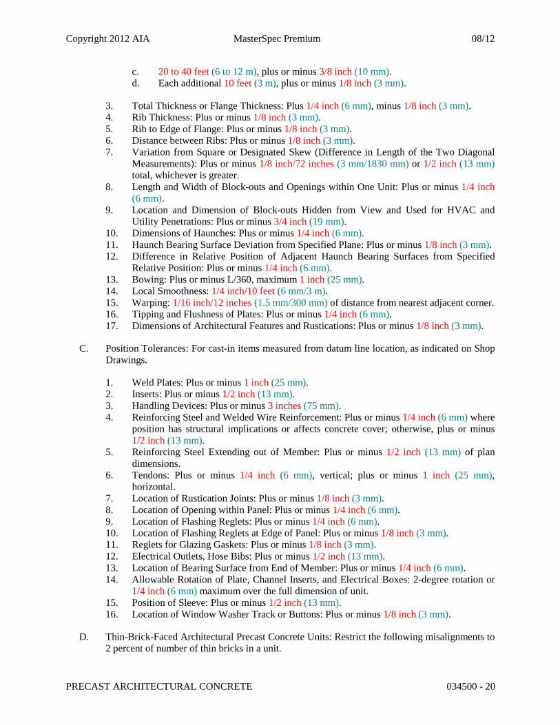
c. 20 to 40 feet (6 to 12 m), plus or minus 3/8 inch (10 mm). d. Each additional 10 feet (3 m), plus or minus 1/8 inch (3 mm).
3. Total Thickness or Flange Thickness: Plus 1/4 inch (6 mm), minus 1/8 inch (3 mm). 4. Rib Thickness: Plus or minus 1/8 inch (3 mm). 5. Rib to Edge of Flange: Plus or minus 1/8 inch (3 mm). 6. Distance between Ribs: Plus or minus 1/8 inch (3 mm). 7. Variation from Square or Designated Skew (Difference in Length of the Two Diagonal
Measurements): Plus or minus 1/8 inch/72 inches (3 mm/1830 mm) or 1/2 inch (13 mm) total, whichever is greater.
8. Length and Width of Block-outs and Openings within One Unit: Plus or minus 1/4 inch (6 mm).
9. Location and Dimension of Block-outs Hidden from View and Used for HVAC and Utility Penetrations: Plus or minus 3/4 inch (19 mm).
10. Dimensions of Haunches: Plus or minus 1/4 inch (6 mm). 11. Haunch Bearing Surface Deviation from Specified Plane: Plus or minus 1/8 inch (3 mm). 12. Difference in Relative Position of Adjacent Haunch Bearing Surfaces from Specified
Relative Position: Plus or minus 1/4 inch (6 mm). 13. Bowing: Plus or minus L/360, maximum 1 inch (25 mm). 14. Local Smoothness: 1/4 inch/10 feet (6 mm/3 m). 15. Warping: 1/16 inch/12 inches (1.5 mm/300 mm) of distance from nearest adjacent corner. 16. Tipping and Flushness of Plates: Plus or minus 1/4 inch (6 mm). 17. Dimensions of Architectural Features and Rustications: Plus or minus 1/8 inch (3 mm).
C. Position Tolerances: For cast-in items measured from datum line location, as indicated on Shop Drawings.
1. Weld Plates: Plus or minus 1 inch (25 mm). 2. Inserts: Plus or minus 1/2 inch (13 mm). 3. Handling Devices: Plus or minus 3 inches (75 mm). 4. Reinforcing Steel and Welded Wire Reinforcement: Plus or minus 1/4 inch (6 mm) where
position has structural implications or affects concrete cover; otherwise, plus or minus 1/2 inch (13 mm).
5. Reinforcing Steel Extending out of Member: Plus or minus 1/2 inch (13 mm) of plan dimensions.
6. Tendons: Plus or minus 1/4 inch (6 mm), vertical; plus or minus 1 inch (25 mm), horizontal.
7. Location of Rustication Joints: Plus or minus 1/8 inch (3 mm). 8. Location of Opening within Panel: Plus or minus 1/4 inch (6 mm). 9. Location of Flashing Reglets: Plus or minus 1/4 inch (6 mm). 10. Location of Flashing Reglets at Edge of Panel: Plus or minus 1/8 inch (3 mm). 11. Reglets for Glazing Gaskets: Plus or minus 1/8 inch (3 mm). 12. Electrical Outlets, Hose Bibs: Plus or minus 1/2 inch (13 mm). 13. Location of Bearing Surface from End of Member: Plus or minus 1/4 inch (6 mm). 14. Allowable Rotation of Plate, Channel Inserts, and Electrical Boxes: 2-degree rotation or
1/4 inch (6 mm) maximum over the full dimension of unit. 15. Position of Sleeve: Plus or minus 1/2 inch (13 mm). 16. Location of Window Washer Track or Buttons: Plus or minus 1/8 inch (3 mm).
D. Thin-Brick-Faced Architectural Precast Concrete Units: Restrict the following misalignments to 2 percent of number of thin bricks in a unit.
Copyright 2012 AIA MasterSpec Premium 08/12
PRECAST ARCHITECTURAL CONCRETE 034500 - 21
1. Alignment of Mortar Joints:
a. Jog in Alignment: 1/8 inch (3 mm). b. Alignment with Panel Centerline: Plus or minus 1/8 inch (3 mm).
2. Variation in Width of Exposed Mortar Joints: Plus or minus 1/8 inch (3 mm). 3. Tipping of Individual Thin Bricks from the Panel Plane of Exposed Thin-Brick Surface:
Plus 0 inch (0 mm); minus 1/4 inch (6 mm) less than or equal to depth of form liner joint. 4. Exposed Thin-Brick Surface Parallel to Primary Control Surface of Panel: Plus 1/4 inch
(6 mm); minus 1/8 inch (3 mm). 5. Individual Thin-Brick Step in Face from Panel Plane of Exposed Thin-Brick Surface:
Plus 0 inch (0 mm); minus 1/4 inch (6 mm) less than or equal to depth of form liner joint.
E. Stone Veneer-Faced Architectural Precast Concrete Units:
1. Variation in Cross-Sectional Dimensions: For thickness of walls from dimensions indicated: Plus or minus 1/4 inch (6 mm).
2. Variation in Joint Width: 1/8 inch in 36 inches (3 mm in 900 mm) or a quarter of nominal joint width, whichever is less.
3. Variation in Plane between Adjacent Stone Units (Lipping): 1/16-inch (1.5-mm) difference between planes of adjacent units.
2.22 FINISHES
A. Exposed faces shall be free of joint marks, grain, and other obvious defects. Corners, including false joints shall be uniform, straight, and sharp. Finish exposed-face surfaces of architectural precast concrete units to match approved [design reference sample] [sample panels] [mockups] and as follows:
1. Design Reference Sample: <Insert description and identify fabricator and code number of sample>.
2. PCI's "Architectural Precast Concrete - Color and Texture Selection Guide," of plate numbers indicated.
3. As-Cast Surface Finish: Provide surfaces to match approved sample for acceptable surface, air voids, sand streaks, and honeycomb.
4. Textured-Surface Finish: Impart by form liners or inserts. 5. Bushhammer Finish: Use power or hand tools to remove matrix and fracture coarse
aggregates. 6. Exposed-Aggregate Finish: Use chemical retarding agents applied to concrete forms and
washing and brushing procedures to expose aggregate and surrounding matrix surfaces after form removal.
7. Abrasive-Blast Finish: Use abrasive grit, equipment, application techniques, and cleaning procedures to expose aggregate and surrounding matrix surfaces.
8. Acid-Etched Finish: Use acid and hot-water solution, equipment, application techniques, and cleaning procedures to expose aggregate and surrounding matrix surfaces. Protect hardware, connections, and insulation from acid attach.
9. Honed Finish: Use continuous mechanical abrasion with fine grit, followed by filling and rubbing procedures.
10. Polished Finish: Use continuous mechanical abrasion with fine grit, followed by filling and rubbing procedures.

Copyright 2012 AIA MasterSpec Premium 08/12
PRECAST ARCHITECTURAL CONCRETE 034500 - 22
11. Sand-Embedment Finish: Use selected stones placed in a sand bed in bottom of mold, with sand removed after curing.
12. Thin-Brick Facing: See "Thin-Brick Facings" Article. 13. Stone Facing: See "Stone Facings" Article.
B. Finish exposed [top] [back] surfaces of architectural precast concrete units to match face-surface finish.
C. Finish exposed [top] [back] surfaces of architectural precast concrete units with smooth, steel-trowel finish.
D. Finish unexposed surfaces of architectural precast concrete units with as cast finish.
2.23 SOURCE QUALITY CONTROL
A. Quality-Control Testing: Test and inspect precast concrete according to PCI MNL 117 requirements. If using self-consolidating concrete, also test and inspect according to PCI TR-6, ASTM C 1610/C 1610M, ASTM C 1611/C 1611M, ASTM C 1621/C 1621M, and ASTM C 1712.
B. Owner will employ an independent testing agency to evaluate architectural precast concrete fabricator's quality-control and testing methods.
1. Allow Owner's testing agency access to material storage areas, concrete production equipment, concrete placement, and curing facilities. Cooperate with Owner's testing agency and provide samples of materials and concrete mixtures as may be requested for additional testing and evaluation.
C. Strength of precast concrete units is considered deficient if units fail to comply with ACI 318 (ACI 318M) requirements for concrete strength.
D. Testing: If there is evidence that strength of precast concrete units may be deficient or may not comply with ACI 318 (ACI 318M) requirements, precaster will employ an independent testing agency to obtain, prepare, and test cores drilled from hardened concrete to determine compressive strength according to ASTM C 42/C 42M and ACI 318 (ACI 318M).
1. A minimum of three representative cores shall be taken from units of suspect strength, from locations directed by Architect.
2. Test cores in an air-dry condition. 3. Strength of concrete for each series of three cores is considered satisfactory if average
compressive strength is equal to at least 85 percent of 28-day design compressive strength and no single core is less than 75 percent of 28-day design compressive strength.
4. Report test results in writing on same day that tests are performed, with copies to Architect, Contractor, and precast concrete fabricator. Test reports include the following:
a. Project identification name and number. b. Date when tests were performed. c. Name of precast concrete fabricator. d. Name of concrete testing agency.
Copyright 2012 AIA MasterSpec Premium 08/12
PRECAST ARCHITECTURAL CONCRETE 034500 - 23
e. Identification letter, name, and type of precast concrete unit(s) represented by core tests; design compressive strength; type of break; compressive strength at breaks, corrected for length-diameter ratio; and direction of applied load to core in relation to horizontal plane of concrete as placed.
E. Patching: If core test results are satisfactory and precast concrete units comply with requirements, clean and dampen core holes and solidly fill with precast concrete mixture that has no coarse aggregate, and finish to match adjacent precast concrete surfaces.
F. Defective Units: Discard and replace recast architectural concrete units that do not comply with acceptability requirements in PCI MNL 117, including concrete strength, manufacturing tolerances, and color and texture range. Chipped, spalled, or cracked units may be repaired, subject to Architect's approval. Architect reserves the right to reject precast units that do not match approved samples, sample panels, and mockups. Replace unacceptable units with precast concrete units that comply with requirements.
PART 3 - EXECUTION
3.1 EXAMINATION
A. Examine supporting structural frame or foundation and conditions for compliance with requirements for installation tolerances, bearing surface tolerances, and other conditions affecting performance of the Work.
B. Do not install precast concrete units until supporting cast-in-place concrete has attained minimum allowable design compressive strength and supporting steel or other structure is structurally ready to receive loads from precast concrete units.
C. Proceed with installation only after unsatisfactory conditions have been corrected.
3.2 INSTALLATION
A. Install clips, hangers, bearing pads, and other accessories required for connecting architectural precast concrete units to supporting members and backup materials.
B. Erect architectural precast concrete level, plumb, and square within specified allowable tolerances. Provide temporary supports and bracing as required to maintain position, stability, and alignment of units until permanent connections are completed.
1. Install temporary steel or plastic spacing shims as precast concrete units are being erected. Tack weld steel shims to each other to prevent shims from separating.
2. Maintain horizontal and vertical joint alignment and uniform joint width as erection progresses.
3. Remove projecting lifting devices and grout fill voids within recessed lifting devices flush with surface of adjacent precast surfaces when recess is exposed.
4. Unless otherwise indicated, maintain uniform joint widths of 3/4 inch (19 mm).
Copyright 2012 AIA MasterSpec Premium 08/12
PRECAST ARCHITECTURAL CONCRETE 034500 - 24
C. Connect architectural precast concrete units in position by bolting, welding, grouting, or as otherwise indicated on Shop Drawings. Remove temporary shims, wedges, and spacers as soon as practical after connecting and grouting are completed.
1. Do not permit connections to disrupt continuity of roof flashing.
D. Welding: Comply with applicable requirements in AWS D1.1/D1.1M and AWS D1.4/D1.4M for welding, welding electrodes, appearance, quality of welds, and methods used in correcting welding work.
1. Protect architectural precast concrete units and bearing pads from damage by field welding or cutting operations, and provide noncombustible shields as required.
2. Welds not specified shall be continuous fillet welds, using no less than the minimum fillet as specified by AWS.
3. Clean weld-affected metal surfaces with chipping hammer followed by brushing, and apply a minimum 4.0-mil- (0.1-mm-) thick coat of galvanized repair paint to galvanized surfaces according to ASTM A 780/A 780M.
4. Clean weld-affected metal surfaces with chipping hammer followed by brushing, and reprime damaged painted surfaces.
5. Visually inspect welds and remove, reweld, or repair incomplete and defective welds.
E. At bolted connections, use lock washers, tack welding, or other approved means to prevent loosening of nuts after final adjustment.
1. Where slotted connections are used, verify bolt position and tightness. For sliding connections, properly secure bolt but allow bolt to move within connection slot.
2. For slip-critical connections, use one of the following methods to assure proper bolt pretension:
a. Turn-of-Nut: According to RCSC's "Specification for Structural Joints Using ASTM A 325 or A 490 Bolts."
b. Calibrated Wrench: According to RCSC's "Specification for Structural Joints Using ASTM A 325 or A 490 Bolts."
c. Twist-off Tension Control Bolt: ASTM F 1852. d. Direct-Tension Control Bolt: ASTM F 1852.
3. For slip-critical connections, use method and inspection procedure approved by Architect and coordinated with inspection agency.
F. Grouting or Dry-Packing Connections and Joints: Grout connections where required or indicated. Retain flowable grout in place until hard enough to support itself. Alternatively, pack spaces with stiff dry-pack grout material, tamping until voids are completely filled. Place grout and finish smooth, level, and plumb with adjacent concrete surfaces. Promptly remove grout material from exposed surfaces before it affects finishes or hardens. Keep grouted joints damp for not less than 24 hours after initial set.
3.3 ERECTION TOLERANCES
A. Erect architectural precast concrete units level, plumb, square, and in alignment without exceeding the noncumulative erection tolerances of PCI MNL 117, Appendix I.
Copyright 2012 AIA MasterSpec Premium 08/12
PRECAST ARCHITECTURAL CONCRETE 034500 - 25
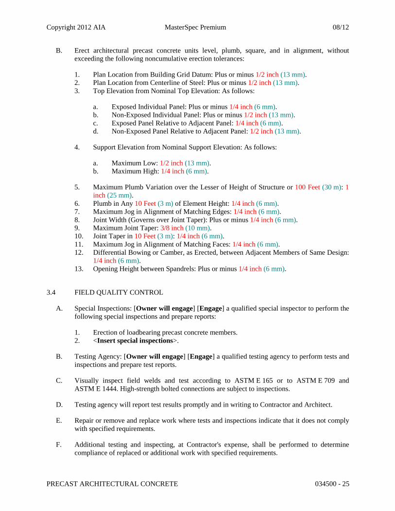
B. Erect architectural precast concrete units level, plumb, square, and in alignment, without exceeding the following noncumulative erection tolerances:
1. Plan Location from Building Grid Datum: Plus or minus 1/2 inch (13 mm). 2. Plan Location from Centerline of Steel: Plus or minus 1/2 inch (13 mm). 3. Top Elevation from Nominal Top Elevation: As follows:
a. Exposed Individual Panel: Plus or minus 1/4 inch (6 mm). b. Non-Exposed Individual Panel: Plus or minus 1/2 inch (13 mm). c. Exposed Panel Relative to Adjacent Panel: 1/4 inch (6 mm). d. Non-Exposed Panel Relative to Adjacent Panel: 1/2 inch (13 mm).
4. Support Elevation from Nominal Support Elevation: As follows:
a. Maximum Low: 1/2 inch (13 mm). b. Maximum High: 1/4 inch (6 mm).
5. Maximum Plumb Variation over the Lesser of Height of Structure or 100 Feet (30 m): 1 inch (25 mm).
6. Plumb in Any 10 Feet (3 m) of Element Height: 1/4 inch (6 mm). 7. Maximum Jog in Alignment of Matching Edges: 1/4 inch (6 mm). 8. Joint Width (Governs over Joint Taper): Plus or minus 1/4 inch (6 mm). 9. Maximum Joint Taper: 3/8 inch (10 mm). 10. Joint Taper in 10 Feet (3 m): 1/4 inch (6 mm). 11. Maximum Jog in Alignment of Matching Faces: 1/4 inch (6 mm). 12. Differential Bowing or Camber, as Erected, between Adjacent Members of Same Design:
1/4 inch (6 mm). 13. Opening Height between Spandrels: Plus or minus 1/4 inch (6 mm).
3.4 FIELD QUALITY CONTROL
A. Special Inspections: [Owner will engage] [Engage] a qualified special inspector to perform the following special inspections and prepare reports:
1. Erection of loadbearing precast concrete members. 2. <Insert special inspections>.
B. Testing Agency: [Owner will engage] [Engage] a qualified testing agency to perform tests and inspections and prepare test reports.
C. Visually inspect field welds and test according to ASTM E 165 or to ASTM E 709 and ASTM E 1444. High-strength bolted connections are subject to inspections.
D. Testing agency will report test results promptly and in writing to Contractor and Architect.
E. Repair or remove and replace work where tests and inspections indicate that it does not comply with specified requirements.
F. Additional testing and inspecting, at Contractor's expense, shall be performed to determine compliance of replaced or additional work with specified requirements.
Copyright 2012 AIA MasterSpec Premium 08/12
PRECAST ARCHITECTURAL CONCRETE 034500 - 26
3.5 REPAIRS
A. Repair architectural precast concrete units if permitted by Architect. Architect reserves the right to reject repaired units that do not comply with requirements.
B. Mix patching materials and repair units so cured patches blend with color, texture, and uniformity of adjacent exposed surfaces and show no apparent line of demarcation between original and repaired work, when viewed in typical daylight illumination from a distance of 20 feet (6 m).
C. Prepare and repair damaged galvanized coatings with galvanizing repair paint according to ASTM A 780/A 780M.
D. Wire brush, clean, and paint damaged prime-painted components with same type of shop primer.
E. Remove and replace damaged architectural precast concrete units when repairs do not comply with requirements.
3.6 CLEANING
A. Clean surfaces of precast concrete units exposed to view.
B. Clean mortar, plaster, fireproofing, weld slag, and other deleterious material from concrete surfaces and adjacent materials immediately.
C. Clean exposed surfaces of precast concrete units after erection and completion of joint treatment to remove weld marks, other markings, dirt, and stains.
1. Perform cleaning procedures, if necessary, according to precast concrete fabricator's recommendations. Protect other work from staining or damage due to cleaning operations.
2. Do not use cleaning materials or processes that could change the appearance of exposed concrete finishes or damage adjacent materials.
END OF SECTION 034500


![SECTION 034500 - PRECAST ARCHITECTURAL CONCRETE · Architectural precast concrete cladding [and load-bearing] units. ... PRECAST ARCHITECTURAL CONCRETE 034500 ... Architectural Cladding](https://img.dokumen.tips/doc/110x75/5ae006067f8b9a1c248cb77e/section-034500-precast-architectural-concrete-precast-concrete-cladding-and-load-bearing.jpg)