Embed Size (px)
Citation preview

International Research Journal of Engineering and Technology (IRJET) e-ISSN: 2395-0056
Volume: 08 Issue: 09 | Sep 2021 www.irjet.net p-ISSN: 2395-0072
© 2021, IRJET | Impact Factor value: 7.529 | ISO 9001:2008 Certified Journal | Page 1400
Structural Analysis and Reinforcement Design of a Simply Supported
Bridge at Edayar using CSiBridge Software
Mrs Tina Jose1, Edwin Jolly2, Eldho Stanly3, Manu Biju4, Mareetta Thaus5
1Assistant Professor, Department of Civil Engineering, Viswajyothi College of Engineering and Technology, Vazhakulam, Kerala. India.
2,3,4,5UG Students, Department of Civil Engineering, Viswajyothi College of Engineering and Technology, Vazhakulam, Kerala. India.
---------------------------------------------------------------------***----------------------------------------------------------------------
Abstract - In this study, the superstructure of a simply supported bridge about to be constructed at Edayar- Koothattukulam Road, Piravom, Kerala, India is analysed and the reinforcement is designed. The bridge consists of a single-span having a length of 18 m and a total width of 9.75 m, including two lanes of 3.75 m each and a footpath of 1.5 m on the left acting as a cantilever. The deck of the bridge is supported on three girders, which are placed on elastomeric bearing supported by the abutments. The modelling and analysis of the bridge superstructure are done using the software CSiBridge. CSiBridge is a structural bridge design and analysis software powered by SAPfire. The bridge is analysed according to IRC guidelines and IRC Class A vehicle load is adopted as moving load on the bridge, which is loaded on the two lanes moving at 50 km/hr. The analysis results are obtained for maximum bending moment, shear force, and deflection in the deck slab and the girders. The bridge is then checked for deflection and found to be safe as per the serviceability limit state of deflection according to the specifications of IRC: 112-2011. Further, the reinforcement is designed as per the limit state method and the reinforcement detailing is drawn.
Key Words: Simply supported bridge, Analysis, CSiBridge software, IRC class vehicle, Reinforcement detailing.
1. INTRODUCTION The existing Ramanchira Bridge is situated in Edayar - Kuthattukulam road of Piravom. The Bridge is having a length of 9.30m and an overall width of 4.50m. The traffic through the road has increased and the existing bridge is not sufficient to cater to the present-day traffic needs as it is only a single-lane bridge. Due to the insufficient width of the bridge, the area has become accident-prone. A new estimate is proposed to reconstruct the bridge by demolishing the existing bridge. The overall width of the new bridge including a 1.50m wide footpath on the left side is 9.75 m and the abutment-to-abutment length is 18.00 m.
The design details of the new proposed bridge are provided by the Public Works Department Section Office, Muvattupuzha and the structural analysis is done using CSiBridge software to check the bridge against deflection and to generate the forces required for the design of
reinforcements for the deck slab and the girders. The new bridge is designed as a single span simply supported bridge.
1.1 CSiBridge Software.
CSiBridge is an analysis and bridge designing software. CSiBridge uses a parametric object-based modelling approach when creating bridge systems for analysis. The designers can easily assemble bridge objects of superstructure and substructure and can be assigned into the bridge composition. Then the SAPFire Analysis Engine, built into the CSIBridge Software, automatically transfers the object-based model into a mathematical finite-element model by meshing the materials and assigning material properties. By using the Finite Element modelling structural members can be optimized and innovative cost-saving designs can be obtained. The generation of critical vehicle loading arrangements and analysis of the effects of the loading on a structure can be rapidly achieved and design checks such as those required for steel/composite bridge decks can be made faster, easier and more accurately than by using manual methods. The software is especially useful for the analysis of moving vehicle loads, for this influence-based enveloping analysis is used.
2. TYPES OF LOADS ON THE BRIDGE. The self-weight of the three girders and the deck section that is modelled in the software is automatically calculated and taken into account by the software. The self-weight of other
Fig - 1: Cross-sectional dimensions of the bridge about to be constructed at Edayar-Koothattukulam
Road. [Source: PWD Muvattupuzha.]
International Research Journal of Engineering and Technology (IRJET) e-ISSN: 2395-0056
Volume: 08 Issue: 09 | Sep 2021 www.irjet.net p-ISSN: 2395-0072
© 2021, IRJET | Impact Factor value: 7.529 | ISO 9001:2008 Certified Journal | Page 1401
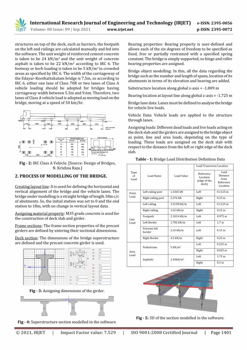
structures on top of the deck, such as barriers, the footpath on the left and railings are calculated manually and fed into the software. The unit weight of reinforced cement concrete is taken to be 24 kN/m3 and the unit weight of concrete asphalt is taken to be 22 kN/m3 according to IRC 6. The footway or kerb loading is taken to be 5 kN/m2 in crowded areas as specified by IRC 6. The width of the carriageway of the Edayar-Koothattukulam bridge is 7.5m, so according to IRC 6, either one lane of Class 70R or two lanes of Class A vehicle loading should be adopted for bridges having carriageway width between 5.3m and 9.6m. Therefore, two lanes of Class A vehicle load is adopted as moving load on the bridge, moving at a speed of 50 km/hr.
2. PROCESS OF MODELLING OF THE BRIDGE. Creating layout line: It is used for defining the horizontal and vertical alignment of the bridge and the vehicle lanes. The bridge under modelling is a straight bridge of length 18m c/c of abutments. So, the initial station was set to 0 and the end station to 18m, with no change in vertical layout data.
Assigning material property: M35 grade concrete is used for the construction of deck slab and girder.
Frame sections: The frame section properties of the precast girders are defined by entering their sectional dimensions.
Deck section: The dimensions of the bridge superstructure are defined and the precast concrete girder is used.
Fig - 3: Assigning dimensions of the girder.
Fig - 4: Superstructure section modelled in the software.
Bearing properties: Bearing property is user-defined and allows each of the six degrees of freedom to be specified as fixed, free or partially restrained with a specified spring constant. The bridge is simply supported, so hinge and roller bearing properties are assigned.
Bridge object modelling: In this, all the data regarding the bridge such as the number and length of spans, location of its abutments in terms of its elevation and bearing are added.
Substructure location along global z-axis = -1.809 m
Bearing location at layout line along global z-axis = -1.725 m
Bridge lane data: Lanes must be defined to analyse the bridge for vehicle live loads.
Vehicle Data: Vehicle loads are applied to the structure through lanes.
Assigning loads: Different dead loads and live loads acting on the deck slab and the girders are assigned to the bridge object as point, line and area loads, depending on the type of loading. These loads are assigned on the deck slab with respect to the distance from the left or right edge of the deck slab.
Table - 1: Bridge Load Distribution Definition Data
Type of
Load Load Name Load Value
Load Transverse Location
Reference Location
(edge of the deck)
Load Distance
from Reference Location
Point Load
Left railing post 1.3365 kN Left 0.1125 m
Right railing post 2.376 kN Right 0.15 m
Line Load
Left railing 1.5138 kN/m Left 0.1125 m
Right railing 1.62 kN/m Right 0.15 m
Footpath 2.1024 kN/m Left 0.975 m
Left Border 1.782 kN/m Left 1.7 m
Extreme left border
2.16 kN/m Left 0.15 m
Right Border 4.2 kN/m Right 0.25 m
Area Load
Pedestrians 5 kN/m2
Left 0.225 m
Right 8.025 m
Asphalts 1.43kN/m2 Left 1.75 m
Right 0.5 m
Fig - 5: 3D of the section modelled in the software.
Fig - 2: IRC Class A Vehicle. [Source: Design of Bridges, N. Krishna Raju.]

International Research Journal of Engineering and Technology (IRJET) e-ISSN: 2395-0056
Volume: 08 Issue: 09 | Sep 2021 www.irjet.net p-ISSN: 2395-0072
© 2021, IRJET | Impact Factor value: 7.529 | ISO 9001:2008 Certified Journal | Page 1402
Fig - 6: 2 IRC Class A vehicles loaded on the bridge.
3. ANALYSIS PROCESS.
Influence based enveloping analysis is used. Vehicles are made to move along the lanes of the bridge. Then, vehicles are automatically placed at positions along the length and width of the lanes to produce the maximum and minimum response quantities throughout the structure, by using the influence surface. Each vehicle can be positioned on every lane or be restricted to act on certain lanes. The program can automatically find the maximum and minimum response quantities throughout the structure for the placement of different vehicles in different lanes. For each maximum and minimum extreme response quantity, the corresponding values for the other components of response can also be computed. The influence lines and surfaces are plotted on the lanes with the influence values plotted in the vertical direction. A positive influence value is plotted upward and the influence values are linearly interpolated between the known values at the load points. Then corresponding to the influence surface/lines generated the maximum and minimum values for shear force, bending moment, deflection, axial force or torsion are generated.
Fig-7: ILD for shear force.
Fig-8: ILD for bending moment.
4. RESULT OF BRIDGE ANALYSIS.
Fig-9: Bending moment diagram for the dead loads.
Fig-10: Bending moment diagram for the moving loads.
Fig-11: Shear force diagram for the dead loads.
Fig-12: Shear force diagram for the moving loads.
Fig-13: Deflection diagram for the dead loads.
Fig-14: Deflection diagram for the moving loads.
Table-2: Maximum values of shear force in the slab and girder. [kN]
Max. S.F. due to Dead Load [kN] (DLSF)
S.F. due to Moving Load [kN] (LLSF)
Design Ultimate Load S.F. [kN] (1.35 DLSF + 1.5 LLSF)
Slab Left Exterior Slab 19.174 19.104 54.541 Interior Slab 23.817 19.002 60.656 Right Exterior Slab 20.282 16.762 52.524 Girder Left Girder 669.7118 272.497 1312.856 Central Girder 374.2549 358.8757 1043.558 Right Girder 472.9146 269.6646 1042.931

International Research Journal of Engineering and Technology (IRJET) e-ISSN: 2395-0056
Volume: 08 Issue: 09 | Sep 2021 www.irjet.net p-ISSN: 2395-0072
© 2021, IRJET | Impact Factor value: 7.529 | ISO 9001:2008 Certified Journal | Page 1403
Table-3: Maximum values of bending moment in the slab and girder. [kNm]
B. M. due to Dead Load [kNm] (DLBM)
B.M. due to Moving Load [kNm] (LLBM)
Design Ultimate Load B.M. [kNm] (1.35 DLBM + 1.5 LLBM)
Slab Left Exterior Slab 13.7625 22.1741 51.841 Interior Slab 13.0345 20.5483 48.419 Right Exterior Slab
12.5417 17.7844 43.608
Girder
Left Girder 2861.1595 1082.1899 5485.850
Central Girder 2024.1588 1109.0503 4396.190 Right Girder 2132.2763 1076.6955 4493.616
Table-4: Maximum values of displacement in the girders (mm)
Due to Dead Load [mm]
(DLBM) Due to Moving Load [mm]
(LLBM) Left Girder 8.2086 2.8559 Central Girder 6.149 2.933 Right Girder 6.5763 3.0709
5. CHECK FOR DEFLECTION. The maximum deflection of the girders are checked against the maximum permissible deflection due to live load ≤ span/800 and total deflection due to dead and live load against the limit for deflection, that is span/250. In both cases, it is found safe according to the serviceability limit state of deflection according to the specifications of IRC: 112-2011. 6. REINFORCEMENT DESIGN AND DETAILING FOR DECK SLAB AND GIRDER. The reinforcement for the deck slab and the three girders were designed according to the limit state of design IS 456:2000. The depth provided and Ast provided was checked and found to be sufficient. Check for the ultimate shear strength was also performed and found to be safe in shear. The girder was designed as a flanged beam where the neutral axis lies in the web portion and it was checked for shear, as per IS 456: 2000 limit state of collapse: shear. All three girders were found to be safe in shear. Shear reinforcements were also designed for the maximum shear obtained in the girders.
Fig-15: Reinforcement detailing for left girder.
Fig-16: Reinforcement detailing for centre and right girder.
Fig-17: Reinforcement detailing for deck slab(Cross-section in the transverse direction).
Fig-18: Reinforcement detailing for deck slab(Cross-section in the longitudinal direction).
CONCLUSIONS In this paper, a single span simply supported bridge with two lanes was modelled and analysed using the CSiBridge software. The analysis results for maximum bending moment, shear force and deflection were obtained corresponding to the deck slab and the three girders. Then the bridge superstructure was checked for deflection and found to be safe according to the serviceability limit state of deflection according to the specifications of IRC: 112-2011. Further, the reinforcement was designed to resist the maximum bending moment and shear force. The deck slab was checked for depth required and the depth provided of 0.225 m was found to be sufficient. The area of steel was calculated for the deck slab according to the maximum bending moment value (51.841 kNm) from the analysis which occurred in the left exterior slab and 16 mm diameter bar was provided at 250 mm spacing centre to centre as the main bar at the bottom. The area of steel provided in the deck slab was then checked for shear against the maximum shear force of 60.656 kN, that is in the interior slab and found to be within the limit. The girder was designed as a flanged beam where the neutral axis lies in the web portion. As the left exterior girder had a greater maximum bending moment value of 5485.85 kNm when compared to the maximum bending moment values of the interior and right
International Research Journal of Engineering and Technology (IRJET) e-ISSN: 2395-0056
Volume: 08 Issue: 09 | Sep 2021 www.irjet.net p-ISSN: 2395-0072
© 2021, IRJET | Impact Factor value: 7.529 | ISO 9001:2008 Certified Journal | Page 1404
exterior girders, 4396.19 kNm and 4493.616 kNm respectively, more area of tension reinforcement was provided for the left exterior girder. Then the girder section was checked for shear as per IS 456: 2000 – limit state of collapse and found to be safe in shear. For the shear force, shear reinforcements were designed for the girders. Finally, the reinforcement detailing is done according to the reinforcement designed for the deck slab and three girders.
REFERENCES [1] R. Shreedhar, Spurti Mamadapur (2012): ‘Analysis of T-
beam Bridge using Finite Element Method’, International Journal of Engineering and Innovative Technology, Volume2, Issue 3.
[2] Ardra M R, Arya K S, Athira M S, Sreelakhmi M S, Prof Kichu Paul (2019): ‘Study and Analysis of Balanced Cantilever Bridge at Kochi Metro’, International Research Journal of Engineering and Technology (IRJET), Vol. 6, Issue 4, April 2019, pp.3518-3522.
[3] Abrar Ahmed, Prof. R.B.Lokhande (2017): ‘Comparative Analysis and Design of T-Beam and Box Girders’, International Research Journal of Engineering and Technology (IRJET), Volume 6, Issue 8, August 2015.
[4] Johnson Victor D (2015): “Essentials of Bridge Engineering”, 7th Edition, Oxford and IBH publishing Co. Ltd, New Delhi, 2015.
[5] N.Krishna Raju (2017): “Design of Bridges”, 5th edition, Oxford and IBH publishing Co.Pvt.Ltd, New Delhi.
[6] Mahendrakar Hemanth Kumar, Dr.Vaishali, G.Ghorpade, Dr.H.Sudarsana Rao (2018): ‘Analysis and Design of Stress Ribbon Bridge with CSiBridge Software’, International Journal of Civil Engineering and Technology (IJCIET), Volume 9, Issue 10, October 2018, pp. 1532–1544.
[7] Viqar Nazir, Mr.Sameer Malhotra (2019): ‘Design of a Prestressed Concrete Bridge and Analysis by CSiBridge’, International Research Journal of Engineering and Technology (IRJET), Volume 6, Issue: 09, Sep 2019.
[8] Miss.Mohini Dhande, Dr.P.P.Saklecha (2016): ‘Comparative Analysis and Design of Solid Deck Slab of Minor Bridge by Effective Width Method and Finite Element Method’, International Journal of Engineering Research & Technology (IJERT), Special Issue – 2016.
[9] Sudarshan Prabhakar Patil, Kameshwar Rao Tallapragada (2017): ‘Analysis and Design of R.C.C. T-girder Bridge under IRC Class AA and Class A Loading’, International Journal of Engineering Research in Mechanical and Civil Engineering (IJERMCE), Vol 2, Issue 3, March 2017.
[10] Nagesh Balekundri, Abhijit Galatage (2020): ‘Stress Distribution and Design of Deck Slab Bridges’, International Research Journal of Engineering and Technology (IRJET), volume 7, Issue 9, Sep 2020.
[11] Bharat Jeswani, Dilip Budhlani (2020): ‘A Review Paper on Analysis and Design of Bridge Components using STAAD.Pro’, International Research Journal of
Engineering and Technology (IRJET), Volume 7, Issue 6, June 2020.
[12] Mohd Ashaari Masrom (2014): ‘A Comparative Study Of The Structural Analysis Between The Integral And The Simply Supported Bridge’, ESTEEM Academic Journal, Vol. 10, June 2014, pages 75-88.
[13] Indian Roads Congress (2017): “Standard Specifications and Code of Practice for Road Bridges”, Section II, Loads and load combinations, 7th Revision, New Delhi, March 2017.
[14] IRC: 21-2000, “Standard Specification and Code of Practice for Bridges”, section: III, Indian Road Congress New Delhi.
[15] IS 456:2000, “Indian Standard Plain and Reinforced Concrete Code of Practice (Fourth Revision)”, BIS, New Delhi.