Embed Size (px)
Citation preview

STRUCTURAL ANALYSIS (ACE008)IARE-R16
B.Tech V Semester
Prepared By:Mr. Suraj BaraikAsst. Professor
Department of Civil Engineering

UNIT-IANALYSIS OF TRUSSES

Truss Bridges
3
A metal truss bridge is a bridge whose main structure comes from atriangular framework of structural steel or iron..

Iron and Steel
Due to their variety of designs, there is a system that is used to classify metal truss
bridges by design.
.
5
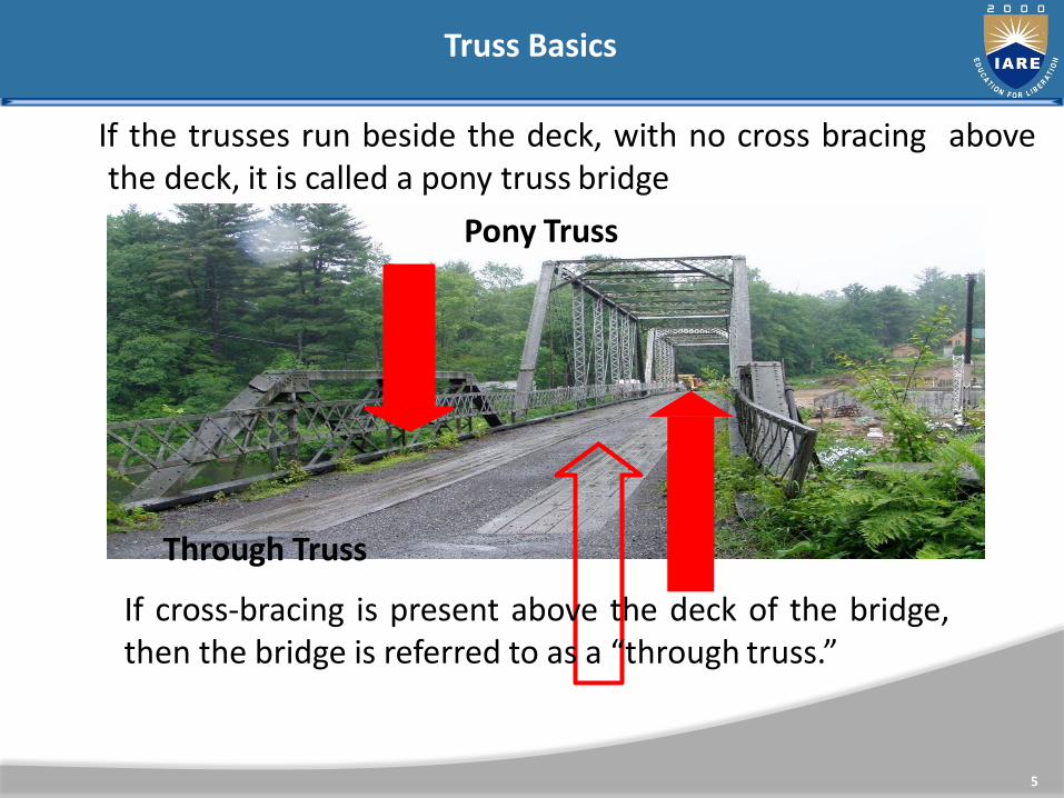
If the trusses run beside the deck, with no cross bracing abovethe deck, it is called a pony truss bridge
Pony Truss
Through Truss
If cross-bracing is present above the deck of the bridge,then the bridge is referred to as a “through truss.”
Truss Basics
Truss Basics
6
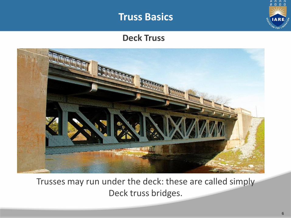
Deck Truss
Trusses may run under the deck: these are called simply Deck truss bridges.

The different parts of a truss bridge are all named. Some of the parts:
Top / Upper Chord Vertical (Member)
Diagonal (Member)
Bottom / Lower Chord
Portal BracingSway Bracing
Lateral Bracing
Floor beam
Connections
End Post
Each spacebetween verticalmembers and endposts is one panel.This bridge has sixpanels.
Truss Bridge Parts
7
Hip Vertical (Only the verticals that meet the top of the end post)

Truss Bridge
Connections
8
The pieces of the framework of a truss bridge are held together byconnections. Most connections on historic bridges are either rivetedor pinned.

9
Pinned connections can be identified by the bolt-like object called a pingoing through the loops of the members. They tend to show up onbridges from the first half of the truss bridge era.
Pinned Connections

Riveted Connections
10
Riveted connections are identified by a “gusset plate” whichdiagonals and vertical members are riveted to, and no pin is present.These connections tend to show up in the second half of the trussbridge era.

Truss Configurations
11
Pratt
Overview: One of the two most common configurations, it tends tooccupy the earlier half of the truss bridge era, but was usedthroughout. Originally developed by Thomas and Caleb Pratt in 1844.
Appearance: Diagonal members angle toward the center andbottom of bridge.
Truss Configurations
12
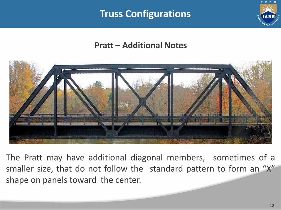
Pratt – Additional Notes
The Pratt may have additional diagonal members, sometimes of asmaller size, that do not follow the standard pattern to form an “X”shape on panels toward the center.

Truss Configurations
13
Whipple
Overview: The Whipple truss is also known as the double- intersectionPratt truss. It was patented by Squire Whipple in 1847 as a strongerversion of the Pratt truss.
Appearance: Similar to the Pratt truss, but the diagonals passthrough one vertical member before reaching the bottom chord.They tend to show up on longer spans built in the first half of thetruss era, and with pinned connections.

Truss Configurations
14
Baltimore
Overview: The Baltimore railroad designed a truss configuration thateventually found use on both railroads and highways. It is a Pratt trusswith additional members added for additional strength.
Appearance: Characterized by a Pratt configuration with extrasmaller members branching off of the diagonals.
Truss Configurations
15
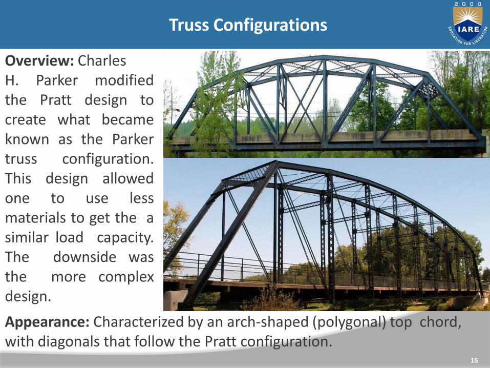
ParkerOverview: CharlesH. Parker modifiedthe Pratt design tocreate what becameknown as the Parkertruss configuration.This design allowedone to use lessmaterials to get the asimilar load capacity.The downside wasthe more complexdesign.
Appearance: Characterized by an arch-shaped (polygonal) top chord, with diagonals that follow the Pratt configuration.

Overview: Sometimes called the Petit truss. Designed by thePennsylvania railroad, this configuration combines the engineering ideasbehind the Baltimore with those of the Parker or Camelback.Appearance: Features an arch-shaped (polygonal) top chord with adiagonal arrangement like the Baltimore.
16
Pennsylvania

Truss Configurations
17
Warren
Overview: The other most common truss configuration, this designtended to be used in the second half of the truss bridge era, and withriveted connections. Originally developed in 1848 by James Warren andWilloughby Monzoni.
Appearance: Alternating diagonal members form a repeating “V”shape. A true Warren does not have vertical members.

Warren: With Verticals
Most Warren truss bridges do in fact feature vertical members. Theymay be referenced simply as “warren with verticals” truss bridges.Vertical members may occur at each connection, or every otherconnection.
18

Double-Intersection Warren
Overview: Often called simply the Double Warren, this is anuncommon truss configuration. Bridges with this configuration oftenhave riveted connections.Appearance: Looks like two Warren trusses offset and superimposedon each other, forming a repeating “X” shape.
19

Lenticular
Overview: One of the rarest bridge designs in the country. Patentedby the Berlin Iron Bridge Company of East Berlin, CT
Appearance: Both the top chord and bottom chord have an archedappearance, forming a distinctive oval or eye-like shape.
20
21
ANALYSIS OF PIN-JOINTED FRAMES (TRUSSES)

Truss/ Frame: A pin jointed frame is a structure made of slender(cross-sectional dimensions quite small compared to length)members pin connected at ends and capable of taking load at joints.Such frames are used as roof trusses to support sloping roofs and asbridge trusses to support deck.
Plane frame: A frame in which all members lie in a single plane iscalled plane frame. They are designed to resist the forces acting inthe plane of frame. Roof trusses and bridge trusses are the exampleof plane frames.
Space frame: If all the members of frame do not lie in a singleplane, they are called as space frame. Tripod, transmission towersare the examples of space frames.
Truss/ Frame
22
23

24

Perfect frame: A pin jointed frame which has got just sufficientnumber of members to resist the loads without undergoingappreciable deformation in shape is called a perfect frame.Triangular frame is the simplest perfect frame and it has 03joints and 03 members.It may be observed that to increase one joint in a perfect frame,two more members are required. Hence, the followingexpression may be written as the relationship betweennumber of joint j, and the number of members m in a perfectframe.m = 2j – 3(a) When LHS = RHS, Perfect frame.(b) When LHS<RHS, Deficient frame.(c) When LHS>RHS, Redundant frame.
25

AssumptionsThe following assumptions are made in the analysis of pin jointedtrusses:
1. The ends of the members are pin jointed (hinged).
2. The loads act only at the joints.
3. Self weight of the members is negligible.
Methods of analysis1. Method of joint2. Method of section3. Method of tension coefficient
26

Problems on method of joints
Problem 1: Find the forces in all the members of the truss shown in figure.
27
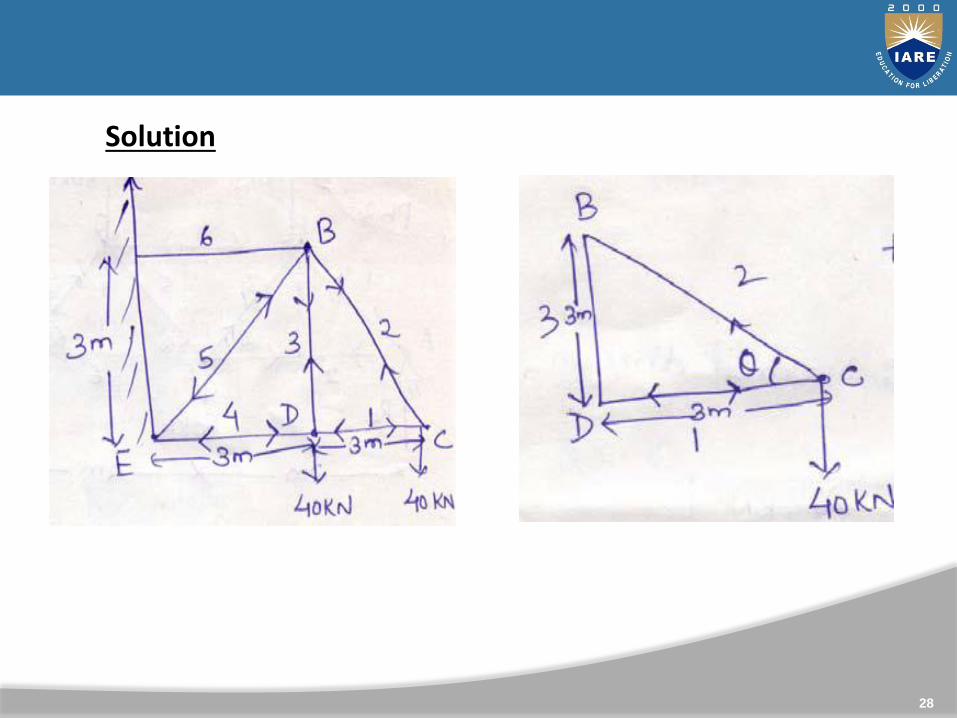
Solution
28

ΣFH=0; ΣFv=0
ΣFH=0; ΣFv=0
29

30
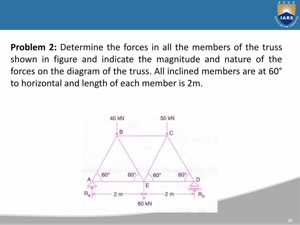
Problem 2: Determine the forces in all the members of the trussshown in figure and indicate the magnitude and nature of theforces on the diagram of the truss. All inclined members are at 60°to horizontal and length of each member is 2m.
31
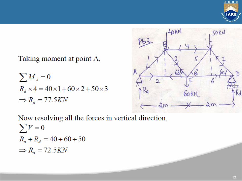
Solution:
32

2
33
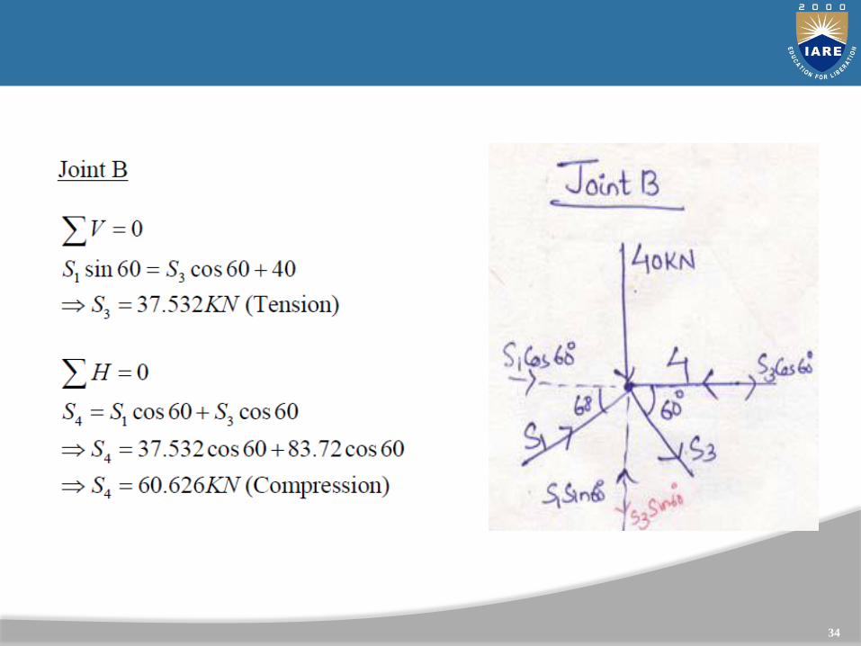
34
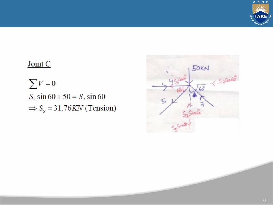
35

Plane Truss ( Method of section)
The method of section is preferable for the following cases:(i) analysis large truss in which forces in only few members arerequired.(ii) if method of joint fails to start or proceed with analysis
Steps of using Method of section- First determine the support reactions- draw a section line passing through not more than threemembers in which forces are unknown, such that the entireframe is cut into two separate parts-each part should be in equilibrium under the action of loads,reaction and the force in the members
36
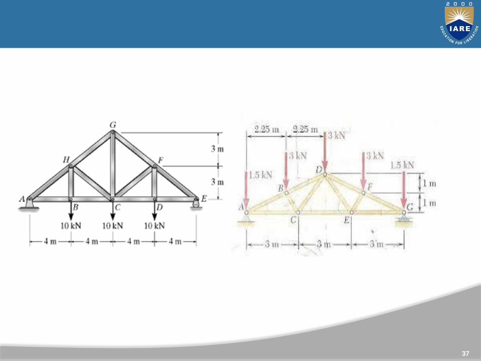
Problem : Determine the member forces of all members of
the trusses shown in Figures below.
Assignment
37
UNIT-IIINTRODUCTION TO ARCHES ANALYSIS

ARCHES
39
An arch looks like curved girder ,either a solid rib or bracedsupported at its ends and carryingtransverse loads which arefrequently vertical .
The early Indian railway andhighways bridges also use masonryarches. Arches are also used inbuildings to carry loads overdoorways, windows etc., as well asto add an aesthetic touch tobuilding.
“An arch can be defined as a humped or curved beam subjected to transverse and other loads as well as the horizontal thrust at the supports.”
40
• It is simplest type of arch, consists of two section hinged at the crown and a hinge at support.
• The hinges at the support makes the ends of the arch to be fixed in position but not in direction.
• It is statically determinate structure.

• In case of beams supporting UDL, the maximum bending momentincreases with the square of the span and hence they becomeuneconomical for long span structures. In such situations archescould be advantageously employed, as they would develophorizontal reactions, which reduces the design bending moment.
• Arches are mainly used in bridge construction and doorways. In earlier days arches were constructed using stones and bricks. In modern times they are being constructed of reinforced concreteand steel.
ARCHES VS BEAMS
41

Arch Terminology
42
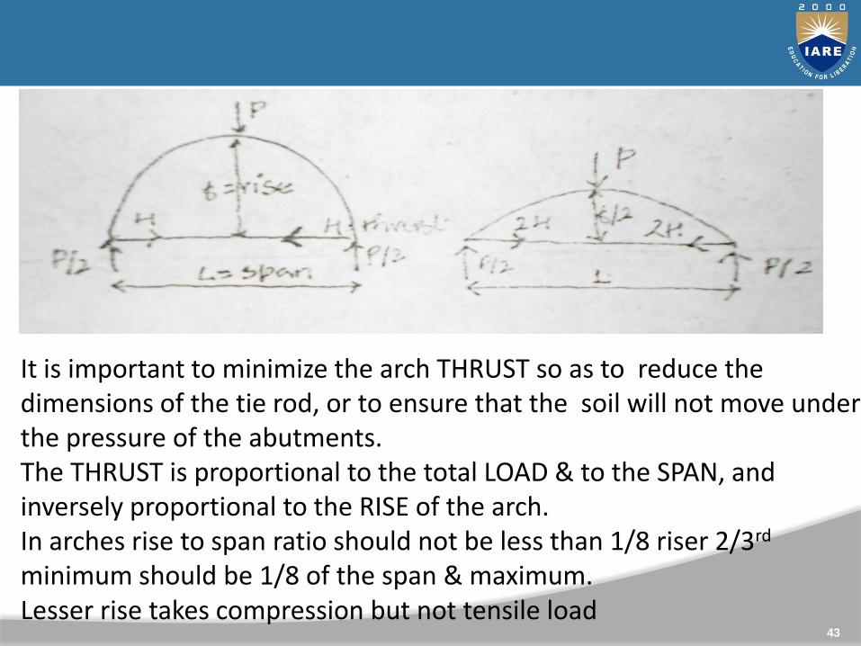
It is important to minimize the arch THRUST so as to reduce the dimensions of the tie rod, or to ensure that the soil will not move under the pressure of the abutments. The THRUST is proportional to the total LOAD & to the SPAN, and inversely proportional to the RISE of the arch.In arches rise to span ratio should not be less than 1/8 riser 2/3rd
minimum should be 1/8 of the span & maximum.Lesser rise takes compression but not tensile load
43
.

In masonry design the arch is
44
heavy & loaded by the weight ofwalls, its shape is usually thefunicular of the dead load, & somebending is introduced in it by liveloads.
In large steel arches, the live loadrepresents a greater share of thetotal load & introduces a largeamount of bending but it is seldom inview of the tensile strength of steel.
The SHAPE of the arch may bechosen to be as close as possible tothe FUNICULAR of the heaviest loads,so as to minimize BENDING.
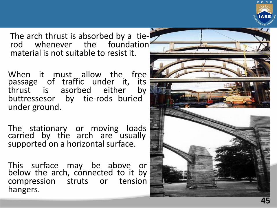
The arch thrust is absorbed by a tie-rod whenever the foundationmaterial is not suitable to resist it.
45
When it must allow the freepassage of traffic under it, its thrust is asorbed either by buttressesor by tie-rods buried under ground.
The stationary or moving loadscarried by the arch are usually supported on a horizontal surface.
This surface may be above orbelow the arch, connected to it bycompression struts or tensionhangers.

MATERIALS USED
46
CONCRETE-takes more compression
STEEL-takes more tension
WOOD-both evenly

LOAD APPLICATIONS
47
FUNICULAR ARCHES – CONCENTRATED LOADS
The sum total of all rotational effects produced about any suchlocation by the external and internal forces must be zero. In threehinged arch having a non-funicular shape, this observation is trueonly at three hinged conditions.The external shear at a section is balanced by an internal resistingshear force that is provided by vertical component of the internalaxial force.

DESIGN OF ARCH STRUCTURES
48
The first important consideration when designing a brick arch iswhether the arch is structural or non-structural. That is, will thearch be required to transfer vertical loads to abutments or will it befully supported by a steel angle.
While this may seem obvious, confusion often develops because ofthe many configurations of arch construction.
To answer this question, one must consider the two structuralrequirements necessary for a brick arch to adequately carryvertical loads.
First, vertical loads must be carried by the arch and transferred tothe abutments. Second, vertical load and lateral thrust from thearch must be resisted by the abutments.

If either the arch or the abutment is deficient, the arch must be considered as non-structural and the arch and its tributary load must be fully supported by a steel angle or plates.
Alternately, reinforcement may be used to increase the strength ofeither or both the arch and the abutments.DESIGNING FOR LOADVARIATIONS
One of the most significantaspect of the modern arch isthat it can be designed tosustain some amount ofvariation in load without eitherchanging shape or experiencingdamage.
49
The shape of an arch is initiallydetermined as a response to itsprimary loading condition (e.g.:parabolic for uniformly distributedloads)

LINEAR(THEORETICAL) ARCHES:
50
Consider a system of jointed link work inverted about AB, withloads and shown in figure:
Under a given system of loading , every link will be in a state ofcompression. The magnitudes of pushes T1,T2,T3,T4….. etc. can beknown by the rays Od, Oe, Of, etc. in the force polygon. Theactual lines of action of pushes T1,T2,T3….. etc. is known as the lineararch or theoretical arch.

In practice the piston and magnitude of the loading over astructure goes on changing. It is therefore neither advisable norpossible to construct an arch according to its theoretical shape.In practice , the arch is made parabolic, circular or ellipse inshape for easy construction and aesthetic appearance. Such anarch is called actual arch.
51
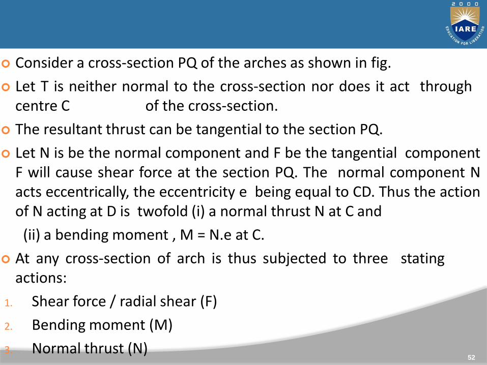
Consider a cross-section PQ of the arches as shown in fig.
Let T is neither normal to the cross-section nor does it act throughcentre C of the cross-section.
The resultant thrust can be tangential to the section PQ.
Let N is be the normal component and F be the tangential componentF will cause shear force at the section PQ. The normal component Nacts eccentrically, the eccentricity e being equal to CD. Thus the actionof N acting at D is twofold (i) a normal thrust N at C and
(ii) a bending moment , M = N.e at C.
At any cross-section of arch is thus subjected to three statingactions:
1. Shear force / radial shear (F)
2. Bending moment (M)
3. Normal thrust (N)52
TYPES OF ARCHES:
53
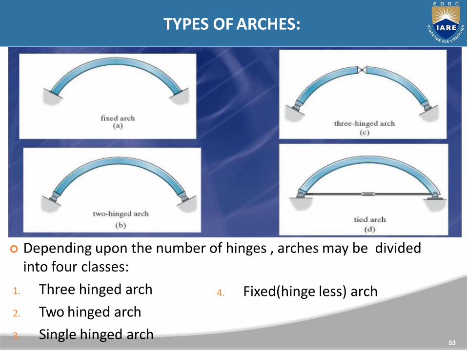
Depending upon the number of hinges , arches may be divided into four classes:
1. Three hinged arch
2. Two hinged arch
3. Single hinged arch
4. Fixed(hinge less) arch
EDDY’S THEOREM:
54
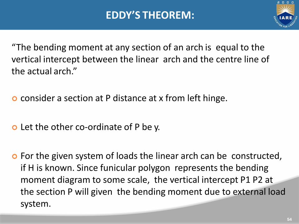
“The bending moment at any section of an arch is equal to the vertical intercept between the linear arch and the centre line of the actual arch.”
consider a section at P distance at x from left hinge.
Let the other co-ordinate of P be y.
For the given system of loads the linear arch can be constructed, if H is known. Since funicular polygon represents the bending moment diagram to some scale, the vertical intercept P1 P2 at the section P will given the bending moment due to external loadsystem.
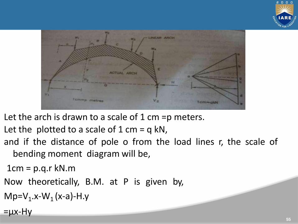
Let the arch is drawn to a scale of 1 cm =p meters.Let the plotted to a scale of 1 cm = q kN,and if the distance of pole o from the load lines r, the scale of
bending moment diagram will be,
1cm = p.q.r kN.m
Now theoretically, B.M. at P is given by,
Mp=V1.x-W1 (x-a)-H.y
=µx-Hy55

EDDY’S THEOREM:
56
“The bending moment at any section of an arch is equal to thevertical intercept between the linear arch and the centre lineof the actual arch.”
consider a section at P distance at x from left hinge.
Let the other co-ordinate of P be y.
For the given system of loads the linear arch can be constructed,if H is known. Since funicular polygon represents the bendingmoment diagram to some scale, the vertical intercept P1 P2 atthe section P will given the bending moment due to externalload system.

Where, µx = V1.x-W1 (x-a)
57
= usual bending moment at a section due toload system on a simply supported beam.
From figure we having,
µx = P1P2* scale of B.M. dia.
= P1P2(p.q.r)
Hy=PP2* scale of B.M. dia.
=PP2 (p.q.r)
Hence,
Mp=µ.x-H.y
= P1P2(p.q.r) – PP2 (p.q.r)
=PP1 (p.q.r)

THREE HINGED ARCH:
58
This is a statically determinate structure.
A three hinged arch has two hinges at abutments and one hinge at the crown.

Let the arch is subjected to a number of loadsW1,W2,W3…etc.
Since B.M. @ c is zero,Mc=µc - H.y= 0
H=µc/y… horizontal thrust. Resolving forces along
the section P,
F= VcosѲ – HsinѲ…..(1) radial shear
Similarly, resolving forces normal to the section, N=VcosѲ +
HsinѲ…..(2) normal thrust
59
THREE HINGED PARABOLIC ARCH:
60
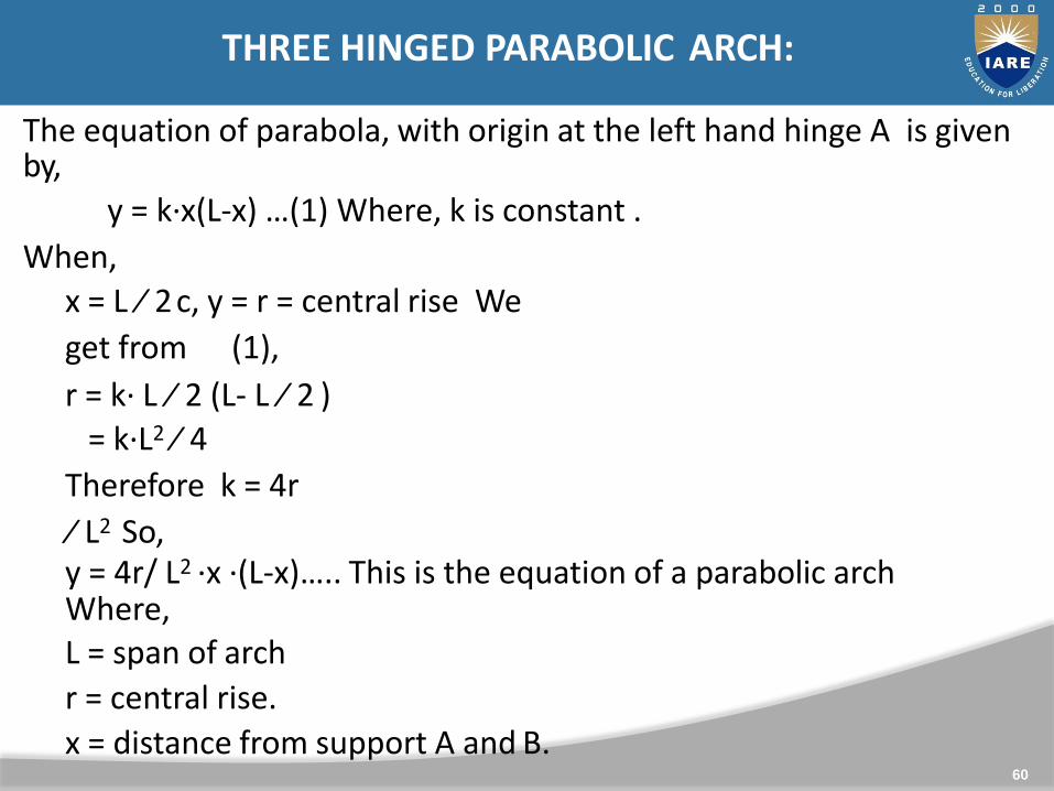
The equation of parabola, with origin at the left hand hinge A is givenby,
y = k∙x(L-x) …(1) Where, k is constant .
When,
x = L ∕ 2c, y = r = central rise We
get from (1),
r = k∙ L ∕ 2 (L- L ∕ 2 )= k∙L2 ∕ 4
Therefore k = 4r
∕ L2 So,y = 4r/ L2 ∙x ∙(L-x)….. This is the equation of a parabolic arch Where,L = span of arch
r = central rise.
x = distance from support A and B.

THREE HINGED CIRCULAR ARCH:
61
Consider the radius of arch is R, subtending an angle of 2θ at the centre. It is more convenient to have the origin at D the middle of span.
Let (x,y) be the co-ordinates of the point P.

From ∆OC1P, x = horizontal distance measured from C.
OP2 =OC12 +C1P2
So, R2={(R-r)+y}2 +x2
Also be the property of circle,
{(2R-R).r}=(L/2)(L/2)=L2/4
62
UNIT-III
FORCE METHOD OF ANALYSIS OF INDETERMINATE BEAMS
6
4
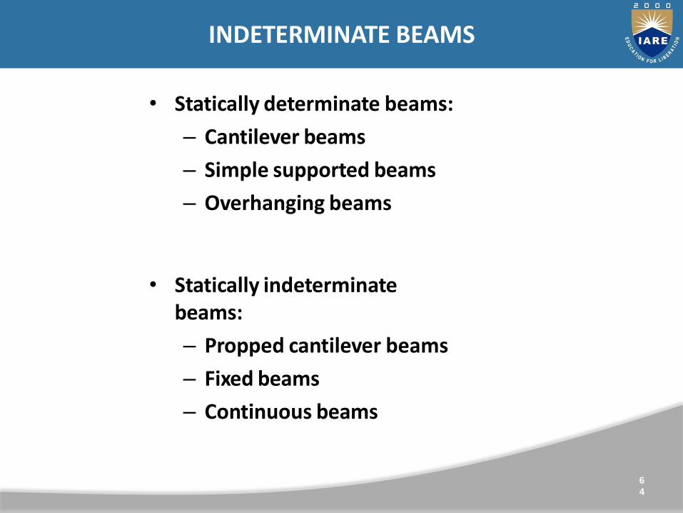
• Statically determinate beams:
– Cantilever beams
– Simple supported beams
– Overhanging beams
• Statically indeterminatebeams:
– Propped cantilever beams
– Fixed beams
– Continuous beams
INDETERMINATE BEAMS

Propped cantilever Beams:
Degree of static indeterminacy= N0. of unknown reactions – static equations=3-2 = 1
6
5

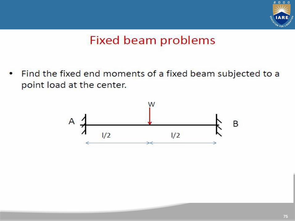
• Fixed beam:
A fixed beam is a beam whose end supports are such that theend slopes remain zero (or unaltered) and is also called a built-inor encaster beam.
INDETERMINATE BEAM: FIXED BEAM
6
6
Degree of static indeterminacy=N0. of unknown reactions – static equations=4-2 =2
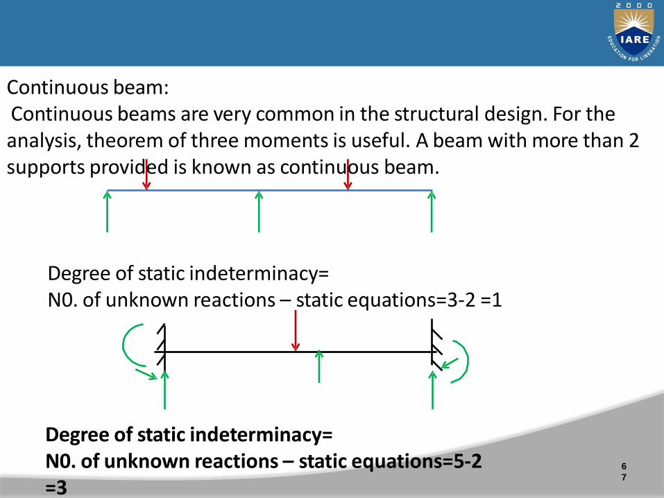
Degree of static indeterminacy=N0. of unknown reactions – static equations=5-2=3
Continuous beam:Continuous beams are very common in the structural design. For theanalysis, theorem of three moments is useful. A beam with more than 2supports provided is known as continuous beam.
Degree of static indeterminacy=N0. of unknown reactions – static equations=3-2 =1
6
7

B.M. diagram for a fixed beam :
Figure shows a fixed beam AB
carrying an external load system.
Let VA and VB be the vertical
reactions at the supports A and B.
Let MA and MB be the fixed end
Moments.
6
8
Fixed Beams

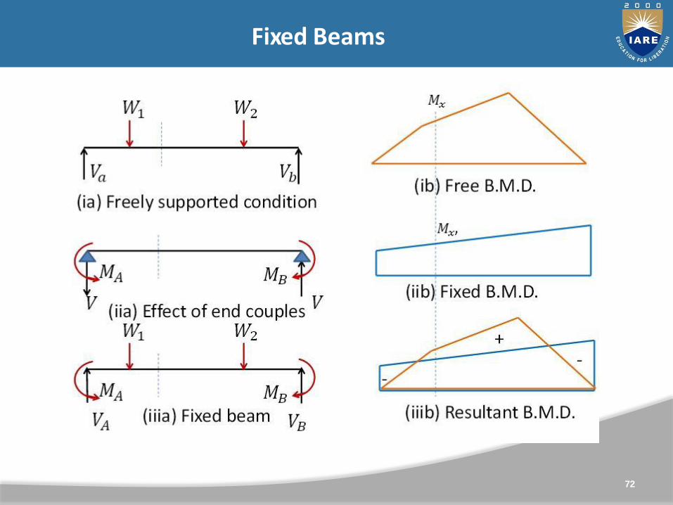
The beam may be analyzed in the following stages.
(i) Let us first consider the beam as Simply supported.
Let va and vb be the vertical reactions at the supports A and B.
Figure (ib) shows the bending moment diagram for thiscondition. At any section the bending moment Mx is a saggingmoment.
(ia) Freely supported condition6
9
(ib) Free B.M.D.
Fixed Beams

(ii) Now let us consider the effect of end couples MA and MB
Fig (iib). Shows the bending moment
diagram for this condition.
At any section the bending moment Mx ͛ is hogging moment.7
0

Now the final bending moment
diagram can be drawn by
combining the above two B.M.
diagrams as shown in Fig. (iiib)
Now the final reaction VA =va- vb
and VB = vb + v
The actual bending moment at anysection X, distance x from the end A is give by
(iiib) Resultant B.M.D.
1071
72
Fixed Beams

B.M. diagram for a fixed beam :
Figure shows a fixed beam AB
carrying an external load system.
Let VA and VB be the vertical
reactions at the supports A and B.
Let MA and MB be the fixed end
Moments.
7
3
Fixed Beams

Fixed Beams
74
Fixed Beams
75

76

77

78

79
UNIT-IV
DISPLACEMENT METHOD OF ANALYSIS
Displacement method of analysis
•Slope deflection method-Analysis of continuous beams andframes (with and without sway)
•Moment distribution method- Analysis of continuous beamsand frames (with and without sway).
81
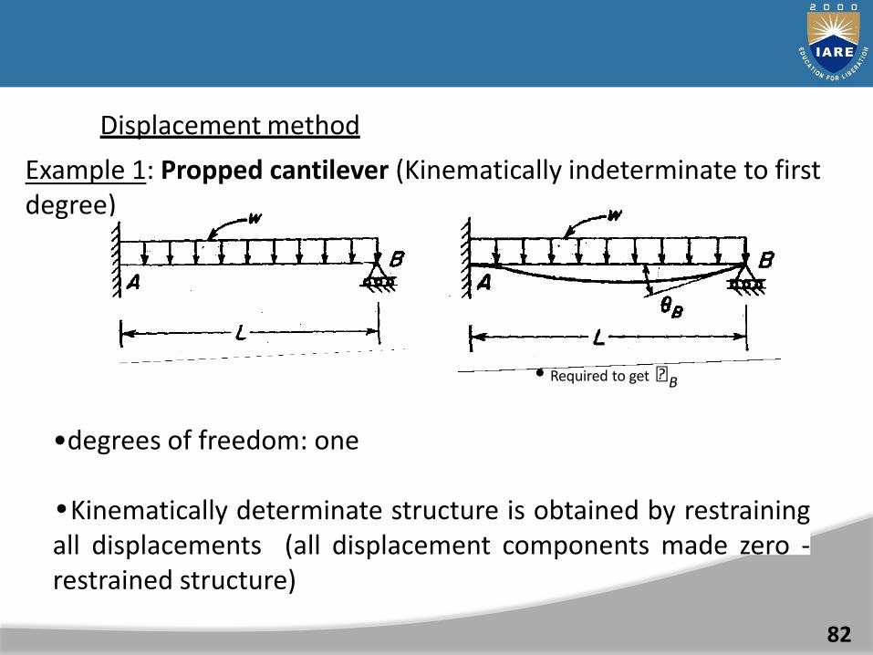
Displacement method
Example 1: Propped cantilever (Kinematically indeterminate to firstdegree)
• Required to get B
•degrees of freedom: one
•Kinematically determinate structure is obtained by restrainingall displacements (all displacement components made zero -restrained structure)
82

Restraint at B causes a reaction of MB as shown.
wL2
M B 12
The actual rotation at B isB
To induce a rotation of B at B, it is required to apply a moment of MBanticlockwise.
4EI
LM
B B
wL3
B 48EI
wL2 4EI
12 B
L
Joint equilibrium equation(or equation of action superposition)
83

A GENERAL APPROACH (APPLYING CONSISTENT SIGNCONVENTION FOR LOADS AND DISPLACEMENTS)
84
•Restrained structure: Restraint at B causes areaction of MB.
MB = wl2/12
(Note the sign conventioclockwise positive)
n:Apply unit rotationcorresponding to B
Let the moment required for this unitrotation be
Moment required to induce a rotation of B
MB mBB 0
85
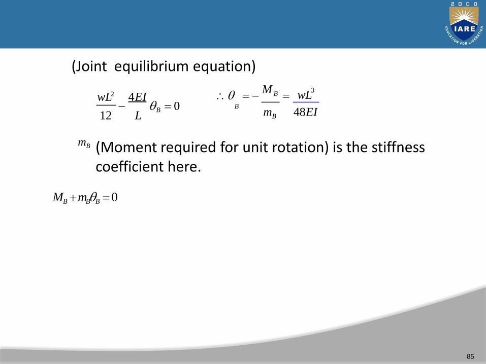
(Joint equilibrium equation)
wL2 4EI3
M B wL
012 L
BmB 48EI
B
mB (Moment required for unit rotation) is the stiffnesscoefficient here.
INTRODUCTION
86
•This method is based on the relationships of end moments withslopes and deflections (called slope-deflection equations) for eachmember.
Approach to solve problems
•The slope-deflection equations are written for each member.
•Joint equilibrium conditions are written.
•Solving the joint equilibrium conditions, unknown displacements arefound out.
•Substituting these unknown displacementsback in the slope-deflection equations, we get the unknown end moments.

DERIVATION OF FUNDAMENTAL EQUATIONS
M BA
M AB
AB
FEM1
ABFEM BA
2
M AB
B
BAM
A
M M
3
AB BA
87

1 Ends assumed as fixed (zero rotation). This requiresrestraining moments (fixed end moments) FEMAB andFEMBA. External loads are acting.
2 Rotations are forced at ends. This requires momentsM’AB and M’BA
3 If there is a support settlement, moments M’’AB
and M’’BA will be induced.
88

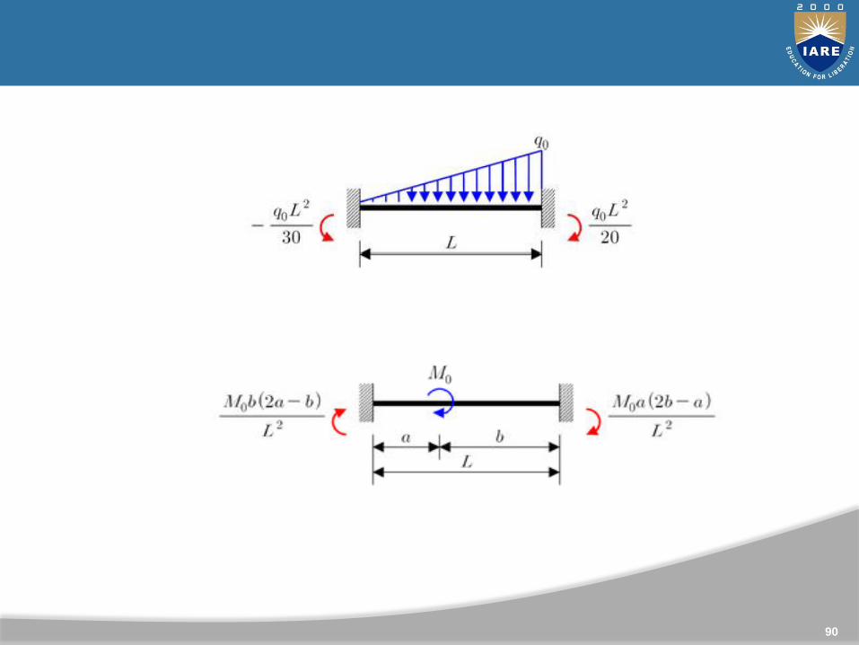
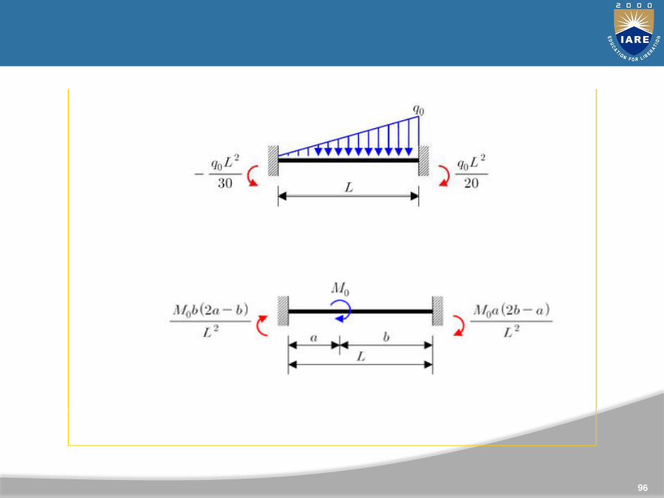
FIXED END MOMENTS
8
PL
PL
8L 2 L 2
89
90

Fixed end moments
8
PL
PL
8L 2 L 2
91

92

ILLUSTRATION OF THE METHOD
93
5kN 8kN
2.5m
Example
AB
C3m
5m 5m
Problem structure
CBA
2.4kNm 3.6kNm 5kNm 5kNm
Fixed end moments (reactive)

Fixed end moments
Pab2
5322
l2
Pa2b 532 2
52
2.4kNmFEMAB
l2 52 3.6kNmFEMBA
FEM Pl
85
5kNm
8 8BC
FEM Pl
85
5kNm
8 8CB
Known displacements
A C 0 A B C 0

FIXED END MOMENTS
8
PL
PL
8L 2 L 2
95
96

97
5kN 8kN
2.5m
Example
AB
C3m
5m 5m
Problem structure
CBA
2.4kNm 3.6kNm 5kNm 5kNm
Fixed end moments (reactive)

Fixed end momentsPab2
5322
l2
Pa2b 532 2
52
2.4kNmFEMAB
l2 52 3.6kNmFEMBA
FEM Pl
85
5kNm
8 8BC
FEM Pl
85
5kNm
8 8CB
Known displacements
A C 0 A B C 0

UNIT-V
MOVING LOADS AND INFLUENCE LINES

Definition : An influence line is a plot of the magnitude of the resulting reaction/axial force/shear/moment generated in a beam or structure as a unit load travels across its length.
Influence lines can be generated for any of these actions (reactions, axial forces, shears, or moments) in a structure.
100
INTRODUCTION TO INFLUENCE LINE

WHY WE USE INFLUENCE LINES
Influence lines are used
1. To determine where to place moving loads on a structure to obtain maximum results (reactions, shears, moments, axial forces).
1. To compute these reactions or other actions (shears/moments/axial forces) once the loads are placed in critical positions.
101

A TYPICAL INFLUENCE LINE
102
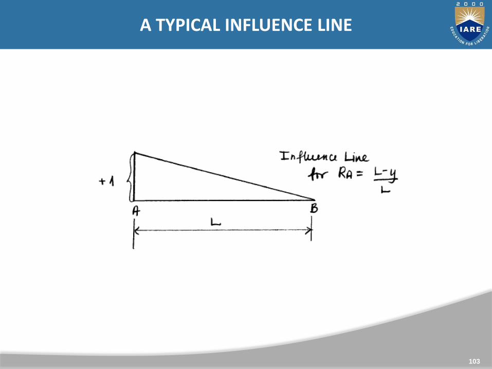
A TYPICAL INFLUENCE LINE
103

A TYPICAL INFLUENCE LINE
104
A Typical Influence line

INFLUENCE LINE OF MOVING LOAD
105
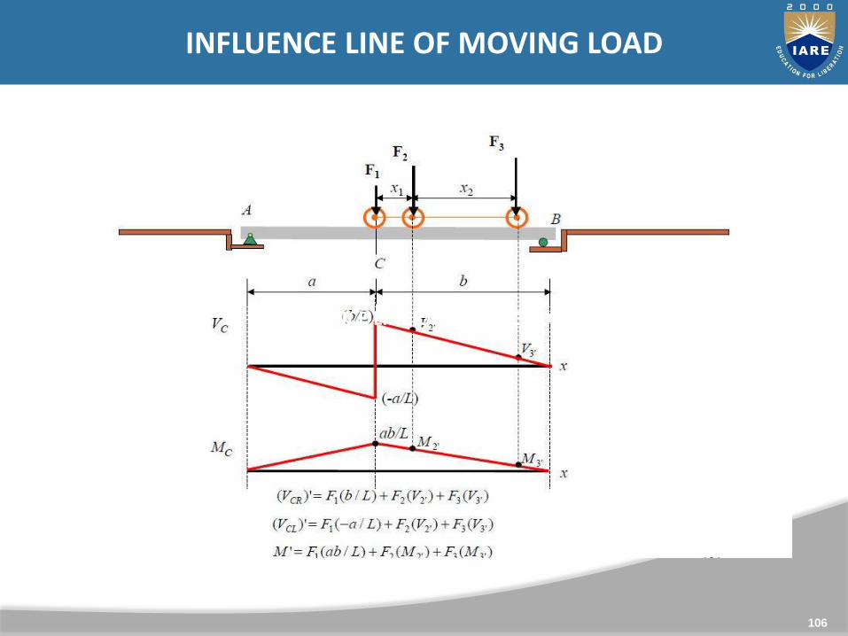
INFLUENCE LINE OF MOVING LOAD
106
INFLUENCE LINE OF MOVING LOAD

INFLUENCE LINE OF MOVING LOAD
107
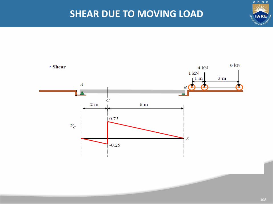
SHEAR DUE TO MOVING LOAD
108

109
SHEAR DUE TO MOVING LOAD
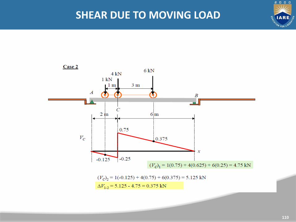
110
SHEAR DUE TO MOVING LOAD

111
SHEAR DUE TO MOVING LOAD

112