Embed Size (px)
Citation preview

1
COMPUTER AIDED MODELLING AND ANALYSIS
LABORATORY
LAB MANUAL
Course Code : AME114
Regulations : IARE -R16
Class : IV Year I Semester (ME)
Prepared by
Mrs. T Vanaja, Assistant Professor
Department of Mechanical Engineering
INSTITUTE OF AERONAUTICAL ENGINEERING (Autonomous)
Dundigal – 500 043, Hyderabad

2
INSTITUTE OF AERONAUTICAL ENGINEERING
(Autonomous)
Dundigal, Hyderabad-500 043
Program Outcomes
PO1 Engineering Knowledge: Capability to apply knowledge of Mathematics, Science Engineering in the field of Mechanical Engineering
PO2 Problem Analysis: An ability to analyze complex engineering problems to arrive at relevant conclusion using knowledge of Mathematics, Science and Engineering.
PO3 Design/ Development of solution: Competence to design a system, component or process to meet societal needs within realistic constants.
PO4 Conduct investigation of complex problems: To design and conduct research oriented experiments as well as to analyze and implement data using research methodologies.
PO5 Modern Tool usage: An ability to formulate solve complex engineering problems using modern engineering and information technology tools.
PO6 The Engineer society: To utilize the engineering practices, techniques, skills to meet needs of health, safety legal, cultural and societal issues.
PO7 Environment and Sustainability: To understand the impact of engineering solution in the societal context and demonstrate the knowledge for sustainable development.
PO8 Ethics: An understanding and implementation of professional and Ethical responsibilities.
PO9 Individual Team work: To function as an effective individual and as a member or leader in multi- disciplinary environment and adopt in diverse teams.
PO10 Communication: An ability to assimilate, comprehends, communicate, give and receive instructions to
present effectively with engineering community and society.
PO11 Project Management and Finance: An ability to provide leadership in managing complex engineering project at multi-disciplinary environment and to become a professional engineer.
PO12 Life-Long learning: Recognition of the need and an ability to engage in lifelong learning to keep abreast with technological changes.
Program Specific Outcomes
PSO1 Professional Skills: To produce engineering professional capable of synthesizing and analyzing mechanical system including allied engineering streams.
PSO2 Design/ Analysis: An ability to adapt and integrate current technologies in the design and manufacturing domain to enhance the employability.
PSO3 Successful Career and Entrepreneurship: To build the nation by imparting technological inputsand managerial skills to become a Technocrats.
3
INSTITUTE OF AERONAUTICAL ENGINEERING
(Autonomous)
Dundigal, Hyderabad – 500 043
Certificate
This is to certify that Mr. /Ms.
bearingrollno ofB.Tech semester
branch has satisfactorily
completed laboratory during the academic year
.
SignatureofHOD Signature ofFaculty
Signature ofInternalExaminer Signature of ExternalExaminer

4
INSTRUMENTATION AND CONTROL SYSTEMS LABORATORY
VII Semester: ME
Course Code Category Hours /
EXPERIMENT Credits Maximum Marks
AME114 Core L T P C CIA SEE Total
- - 3 2 30 70 100
Contact Classes:
Nil Tutorial Classes: Nil Practical Classes: 36 Total Classes: 36
OBJECTIVES:
The course should enable the students to:
I. Understand the features and specifications of CAD and 3D Modeling tools.
II. Develop the part design and drafting methods.
III. Use the CAE software and analyse the load conditions.
IV. Execute the results of reaction forces and stress and strain diagrams.
LIST OF EXPERIMENTS
EXPERI
MENT - 1 INTRODUCTION TO CATIA
Familiarization and practicing of drawing and modifying commands, template creation, lettering, object snapping and
sectioning.
EXPERI
MENT - 2 DRAFTING OF SIMPLE 2D DRAWINGS
Prepare the 2D drawings using draw and modify commands for simple geometric assemblies, sectional views for part
drawing and assemblies.
EXPERI
MENT - 3 SOLID MODELING
Preparing the 2D and 3D models (wire frame, surface and solid models) by using B-REP, CSG. Introduction of Boolean
operations. Generation of 2D, 3D models, through protrusion, revolve, sweep.
EXPERI
MENT - 4 CREATING ORTHOGRAPHIC VIEWS FROM SOLID MODELS
Development of orthographic views for assembly drawings and preparation of bill of materials(IC engine components,
Machine tool accessories, Jigs and Fixtures).
EXPERI
MENT - 5 INTRODUCTION TO ANSYS
Determination of deflection and stresses in bar.
EXPERI
MENT - 6 TRUSSES AND BEAMS
Determination of deflection and stresses in 2D and 3D trusses and beams.
EXPERI
MENT - 7 SHELL STRUCTURES
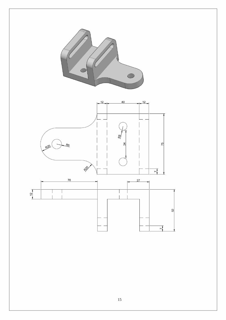
Determination of stresses in 3D and shell structures (one example in each case).

5
EXPERI
MENT - 8 HARMONIC ANALYSIS
Estimation of natural frequencies and mode shapes, harmonic responses of 2D beams.
EXPERI
MENT - 9 HEAT TRANSFER ANALYSIS
Steady state heat transfer analysis of plane and axi-symmetric components
EXPERIM
ENT - 10 CONVENTIONAL REPRESENTATION OF MATERIALS
Conventional representation of parts screw joints, welded joints, springs, gears, electrical, hydraulic and pneumatic
circuits, methods of indicating notes on drawings.
EXPERIM
ENT - 11 LIMTS FITS AND TOLERANCES
Limits, Fits and Tolerances: Types of fits, exercises involving selection, interpretation of fits and estimation of limits
from tables.
EXPERIM
ENT - 12 FORM AND POSITIONAL TOLERANCES
Introduction and indication of form and position tolerances on drawings, types of run out, total run out and their
indication.
EXPERI
MENT -
13
SURFACE ROUHNESS AND ITS INTRODUCTION
Definition, types of surface roughness indication surface roughness obtainable from various manufacturing processes,
recommended surface roughness on mechanical components. Heat treatment and surface treatment symbols used on
drawings.
EXPERIM
ENT - 14 DETAILED AND PART DRAWINGS
Drawing of parts from assembly drawings with indications of size, tolerances, roughness, form and position errors.
EXPERIM
ENT - 15 DETAILED AND PART DRAWINGS
Part drawings using computer aided drafting by CAD software.
Reference Books:
1. K.L. Narayana, P. Kannaiah, ―Production Drawing‖, New Age publishers, 3rd
Edition, 2009
2. Goutham Pohit, Goutham Ghosh, ―Machine Drawing with Auto CAD, Pearson, 1st Edition, 2004.
Web References:
1. https://nptel.ac.in/courses/112107240/

6
ATTAINMENT OF PROGRAM OUTCOMES AND PROGRAM SPECIFICOUTCOMES
Exp.
No.
Experiment
Program
Outcomes
Attained
Program
Specific
Outcomes
Attained 1 Familiarization and practicing of drawing and modifying commands,
template creation, lettering, object snapping and sectioning. PO1, PO2, PO3 PSO1, PSO2
2 Prepare the 2D drawings using draw and modify commands for simple
geometric assemblies, sectional views for part drawing and assemblies. PO1, PO2, PO3 PSO1, PSO2
3 Preparing the 2D and 3D models (wire frame, surface and solid models)
by using B-REP, CSG. Introduction of Boolean operations. Generation
of 2D, 3D models, through protrusion, revolve, sweep.
PO1, PO2, PO3 PSO1, PSO2
4 Development of orthographic views for assembly drawings and
preparation of bill of materials(IC engine components, Machine tool
accessories, Jigs and Fixtures).
PO1, PO2, PO3 PSO1, PSO2
5 Determination of deflection and stresses in bar. PO1, PO2, PO3 PSO1, PSO2
6 Determination of deflection and stresses in 2D and 3D trusses and
beams. PO1, PO2, PO3 PSO1, PSO2
7 Determination of stresses in 3D and shell structures (one example in each
case). PO1, PO2, PO3 PSO1, PSO2
8 Estimation of natural frequencies and mode shapes, harmonic responses
of 2D beams. PO1, PO2, PO3 PSO1, PSO2
9 Steady state heat transfer analysis of plane and axi-symmetric components PO1, PO2, PO3 PSO1, PSO2
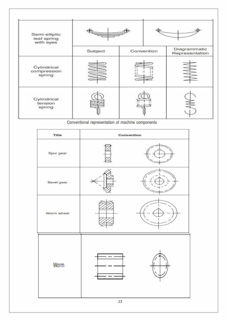
10 Conventional representation of parts screw joints, welded joints, springs,
gears, electrical, hydraulic and pneumatic circuits, methods of indicating
notes on drawings.
PO1, PO2, PO3 PSO1, PSO2
11 Limits, Fits and Tolerances: Types of fits, exercises involving selection,
interpretation of fits and estimation of limits from tables. PO1, PO2, PO3 PSO1, PSO2
12 Introduction and indication of form and position tolerances on drawings,
types of run out, total run out and their indication. PO1, PO2, PO3 PSO1, PSO2
13 Definition, types of surface roughness indication surface roughness
obtainable from various manufacturing processes, recommended surface
roughness on mechanical components. Heat treatment and surface
treatment symbols used on drawings.
PO1, PO2, PO3 PSO1, PSO2
14 Drawing of parts from assembly drawings with indications of size,
tolerances, roughness, form and position errors. PO1, PO2, PO3 PSO1, PSO2
15 Part drawings using computer aided drafting by CAD software. PO1, PO2, PO3 PSO1, PSO2

7
INDEX
S.NO.
NAME OF EXPERIMENT PAGE
NO. DATE REMARK SIGN
1 Familiarization and practicing of drawing and
modifying commands, template creation, lettering,
object snapping and sectioning.
2 Prepare the 2D drawings using draw and modify
commands for simple geometric assemblies,
sectional views for part drawing and assemblies.
3 Preparing the 2D and 3D models (wire frame,
surface and solid models) by using B-REP, CSG.
Introduction of Boolean operations. Generation of
2D, 3D models, through protrusion, revolve, sweep.
4 Development of orthographic views for assembly
drawings and preparation of bill of materials(IC
engine components, Machine tool accessories, Jigs
and Fixtures).
5 Determination of deflection and stresses in bar.
6 Determination of deflection and stresses in 2D and
3D trusses and beams.
7 Determination of stresses in 3D and shell structures
(one example in each case).
8 Estimation of natural frequencies and mode shapes,
harmonic responses of 2D beams.
9 Steady state heat transfer analysis of plane and axi-
symmetric components
10 Conventional representation of parts screw joints,
welded joints, springs, gears, electrical, hydraulic
and pneumatic circuits, methods of indicating notes
on drawings.
11 Limits, Fits and Tolerances: Types of fits, exercises
involving selection, interpretation of fits and
estimation of limits from tables.
12 Introduction and indication of form and position
tolerances on drawings, types of run out, total run
out and their indication.
13 Definition, types of surface roughness indication
surface roughness obtainable from various
manufacturing processes, recommended surface
roughness on mechanical components. Heat
treatment and surface treatment symbols used on
drawings.
14 Drawing of parts from assembly drawings with
indications of size, tolerances, roughness, form and
position errors.
15 Part drawings using computer aided drafting by
CAD software.

8
EXPERIMENT -1
INTRODUCTION TO CATIA
EXERCISE-I

9
EXERCISE -2

10
EXERCISE -3

11
EXPERIMENT -2
DRAFTING OF SIMPLE 2D DRAWINGS

12

13
EXPERIMENT -3
SOLID MODELING

14
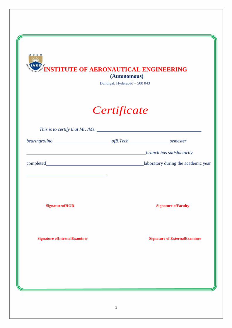
EXPERIMENT -4
CREATING ORTHOGRAPHIC VIEWS FROM SOLID MODELS
15

16
EXPERIMENT – 5
INTRODUCTION TO ANSYS

17
EXPERIMENT- 6
TRUSSES AND BEAMS
18
EXPERIMENT -7
SHELL STRUCTURES

19
EXPERIMENT – 8
HARMONIC ANALYSIS
This tutorial was created using ANSYS 7.0 The purpose of this tutorial is to explain the steps
required to perform Harmonic analysis the cantilever beam shown below.

20
EXPERIMENT- 9
HEAT TRANSFER ANALYSIS

21
EXPERIMENT- 10
CONVENTIONAL REPRESENTATION OF MATERIALS

22
23

24
EXPERIMENT – 11
LIMTS FITS AND TOLERANCES
HOLE AND SAHFT BASIS SYSTEM

25
SCHEMATIC DIAGRAM OF LIMITS AND FITS

26
EXPERIMENT – 12
FORM AND POSITIONAL TOLERANCES

27
EXPERIMENT – 13
SURFACE ROUHNESS AND ITS INTRODUCTION

28
EXPERIMENT – 14
DETAILED AND PART DRAWINGS
29
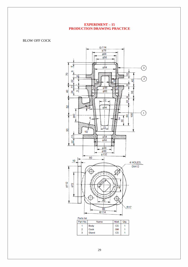
EXPERIMENT – 15
PRODUCTION DRAWING PRACTICE
BLOW OFF COCK
30
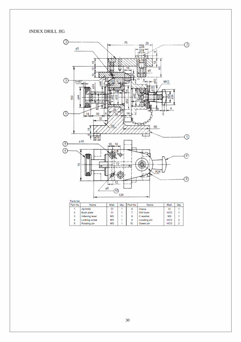
INDEX DRILL JIG

31
SQUARE POST