Embed Size (px)
Citation preview

111HardwareChapterChapterChapter
ULC USR
In This Chapter...Introduction . . . . . . . . . . . . . . . . . . . . . . . . . . . . . . . . . . . . . . . . . . . . . . . . . . . . . . . .1–2
Conventions Used . . . . . . . . . . . . . . . . . . . . . . . . . . . . . . . . . . . . . . . . . . . . . . . . . . .1–2
Product Overview . . . . . . . . . . . . . . . . . . . . . . . . . . . . . . . . . . . . . . . . . . . . . . . . . . .1–3
Managed Switch Accessories . . . . . . . . . . . . . . . . . . . . . . . . . . . . . . . . . . . . . . . . . .1–5
General Information . . . . . . . . . . . . . . . . . . . . . . . . . . . . . . . . . . . . . . . . . . . . . . . . .1–6
LED Indicators . . . . . . . . . . . . . . . . . . . . . . . . . . . . . . . . . . . . . . . . . . . . . . . . . . . . . .1–9
Installation, Plastic Case Switches . . . . . . . . . . . . . . . . . . . . . . . . . . . . . . . . . . . . . .1–11
Installation, Metal Case Switches . . . . . . . . . . . . . . . . . . . . . . . . . . . . . . . . . . . . . .1–12
Power and Alarm Wiring . . . . . . . . . . . . . . . . . . . . . . . . . . . . . . . . . . . . . . . . . . . . .1–25
Communication Ports Wiring . . . . . . . . . . . . . . . . . . . . . . . . . . . . . . . . . . . . . . . . .1–27
Technical Specifications . . . . . . . . . . . . . . . . . . . . . . . . . . . . . . . . . . . . . . . . . . . . . .1–31
IntroductionThe Purpose of this User’s Manual
Thank you for purchasing our Stride™ Industrial Ethernet Switches and Media Converters. This manual describes AutomationDirect.com’s Stride industrial Ethernet switches and media converters, their specifications, included components, and provides you with important information for installation, connectivity and setup. The manual shows you how to install, wire and use the products.
Technical SupportWe strive to make our manuals the best in the industry. We rely on your feedback to let us know if we are reaching our goal. If you cannot find the solution to your particular application, or, if for any reason you need technical assistance, please call us at:
770–844–4200
Our technical support group will work with you to answer your questions. They are available Monday through Friday from 9:00 A.M. to 6:00 P.M. Eastern Time. We also encourage you to visit our web site where you can find technical and non-technical information about our products and our company.
http://www.automationdirect.com
If you have a comment, question or suggestion about any of our products, services, or manuals, please let us know.
Conventions Used
When you see the “notepad” icon in the left-hand margin, the paragraph to its immediate right will be a special note. The word NOTE: in boldface will mark the beginning of the text.
When you see the “exclamation mark” icon in the left-hand margin, the paragraph to its immediate right will be a warning or a caution. This information could prevent injury, loss of property, or even death (in extreme cases). The words WARNING or CAUTION: in boldface will mark the beginning of the text.
Stride Industrial Ethernet Switches User Manual 2nd Ed. Rev. F
Chapter 1 - Hardware
1-2

Stride Industrial Ethernet Switches User Manual 2nd Ed. Rev. F
Chapter 1 - Hardware
Product OverviewStride Unmanaged Ethernet Switches
Part Number Description
SE-SW5U SE-SW5U-WT
STRIDE ™ SlimLine Industrial Unmanaged Ethernet Switch with five 10/100BaseT RJ45 Ethernet ports. Redundant power inputs with surge and spike protection. Auto-crossover. 35 mm DIN rail mounting. Supports store & forward wire speed switching and full-duplex with flow control. UL, CSA (CUL), & CE
Note: -WT models have a metal case and are rated for a wider temperature range, from -40 ° to +85 °C.
SE-SW8U SE-SW8U-WT
STRIDE ™ SlimLine Industrial Unmanaged Ethernet Switch with eight 10/100BaseT RJ45 Ethernet ports. Redundant power inputs with surge and spike protection. Auto-crossover. 35 mm DIN rail mounting. Supports store & forward wire speed switching and full-duplex with flow control. UL, CSA (CUL), & CE
Note: -WT models have a metal case and are rated for a wider temperature range, from -40 ° to +85 °C.
SE-SW5U-ST SE-SW5U-SC SE-SW5U-ST-WT SE-SW5U-SC-WT
STRIDE ™ SlimLine Industrial Unmanaged Ethernet Switch with four 10/100BaseT RJ45 Ethernet Ports and one 100BaseFX Fiber Optic Port (ST or SC type multimode fiber connector for links up to 4km). Redundant power inputs with surge and spike protection. Auto-crossover. 35 mm DIN rail mounting. Supports store & forward wire speed switching and full-duplex with flow control. UL, CSA (CUL), & CE
Note: -WT models have a metal case and are rated for a wider temperature range, from -40 ° to +85 °C.
SE-SW9U-ST SE-SW9U-SC SE-SW9U-ST-WT SE-SW9U-SC-WT
STRIDE ™ SlimLine Industrial Unmanaged Ethernet Switch with eight 10/100BaseT RJ45 Ethernet Ports and one 100BaseFX Fiber Optic Port (ST or SC type multimode fiber connector for links up to 4km). Redundant power inputs with surge and spike protection. Auto-crossover. 35 mm DIN rail mounting. Supports store & forward wire speed switching and full-duplex with flow control. UL, CSA (CUL), & CE
Note: -WT models have a metal case and are rated for a wider temperature range, from -40 ° to +85 °C.
SE-MC2U-ST SE-MC2U-SC
STRIDE ™ SlimLine Industrial Unmanaged Ethernet to Fiber Converter with one 10/100BaseT auto-detecting, auto-crossover and auto-polarity RJ45 Ethernet Port and one 100BaseFX Fiber Optic Port (ST or SC type multimode fiber connector for links up to 4km). Redundant power inputs with surge and spike protection. 35 mm DIN rail mounting. Supports store & forward wire speed switching and full-duplex with flow control. UL, CSA (CUL), & CE
1-3

Stride Industrial Ethernet Switches User Manual 2nd Ed. Rev. F
Chapter 1 - Hardware
Product Overview (cont’d)Stride Managed Ethernet Switches
Part Number Description
SE-SW5M
STRIDE ™ SlimLine industrial managed 5-port Ethernet switch, metal housing, -40 to +75 deg. C operating temperature range, five 10/100BaseT RJ45 Ethernet ports. Redundant power inputs with surge and spike protection, auto-crossover, 35 mm DIN rail mounting. Supports Store and Forward wire speed switching and full-duplex with flow control. UL/CUL HazLoc (Class I, Div. 2, Groups A, B, C, D) and CE marked.
SE-SW5M-2ST SE-SW5M-2SC
STRIDE ™ SlimLine industrial managed 5-port Ethernet switch, metal housing, -40 to +75 deg., three 10/100BaseT RJ45 Ethernet ports and two multi-mode 100BaseFX fiber ports(ST or SC type multimode fiber connector for links up to 4km). Redundant power inputs with surge and spike protection, auto-crossover, 35 mm DIN rail mounting. Supports Store and Forward wire speed switching and full-duplex with flow control. UL/CUL HazLoc (Class I, Div. 2, Groups A, B, C, D) and CE marked.
SE-SW8M
STRIDE ™ SlimLine industrial managed 8-port Ethernet switch, metal housing, -40 to +75 deg. C operating temperature range, eight 10/100BaseT RJ45 Ethernet ports. Redundant power inputs with surge and spike protection, auto-crossover, 35 mm DIN rail mounting. Supports Store and Forward wire speed switching and full-duplex with flow control. UL/CUL HazLoc (Class I, Div. 2, Groups A, B, C, D) and CE marked.
SE-SW8M-2ST SE-SW8M-2SC
STRIDE ™ SlimLine industrial managed 8-port Ethernet switch, metal housing, -40 to +75 deg., six 10/100BaseT RJ45 Ethernet ports and two multi-mode 100BaseFX fiber ports(ST or SC type multimode fiber connector for links up to 4km). Redundant power inputs with surge and spike protection, auto-crossover, 35 mm DIN rail mounting. Supports Store and Forward wire speed switching and full-duplex with flow control. UL/CUL HazLoc (Class I, Div. 2, Groups A, B, C, D) and CE marked.
SE-SW16M
STRIDE ™ SlimLine industrial managed 16-port Ethernet Switch, metal housing, -40 to +75 deg. C operating temperature range, sixteen 10/100BaseT RJ45 Ethernet ports. Redundant power inputs with surge and spike protection, auto-crossover, 35 mm DIN rail mounting. Supports Store and Forward wire speed switching and full-duplex with flow control. UL/CUL HazLoc (Class I, Div. 2, Groups A, B, C, D) and CE marked.
SE-SW8MG-4P
STRIDE ™ SlimLine industrial managed 8-port Ethernet switch all Gigabit, metal housing, -40 to +75 deg., eight 10/100/1000 BaseT RJ45 Ethernet ports and four advanced combination SFP ports that accept noise-immune fiber optic links up to 40 km. Redundant power inputs with surge and spike protection, auto-crossover, 35 mm DIN rail mounting. Supports Store and Forward wire speed switching and full-duplex with flow control. UL/CUL HazLoc (Class I, Div. 2, Groups A, B, C, D) and CE marked. SFP option modules sold separately.
SE-SW10MG-2P
STRIDE ™ SlimLine industrial managed 10-port Ethernet switch with Gigabit, metal housing, -40 to +75 deg., seven 10/100 BaseT RJ45 Ethernet ports, three Gigabit 10/100/1000 BaseT RJ45 port and two advanced combination SFP ports that accept noise-immune fiber optic links up to 40 km. Redundant power inputs with surge and spike protection, auto-crossover, 35 mm DIN rail mounting. Supports Store and Forward wire speed switching and full-duplex with flow control. UL/CUL HazLoc (Class I, Div. 2, Groups A, B, C, D) and CE marked. SFP option modules sold separately.
1-4

Stride Industrial Ethernet Switches User Manual 2nd Ed. Rev. F
Chapter 1 - Hardware
Managed Switch AccessoriesSFP Transceiver
Part Number Description
SFP-4K-FMF
STRIDE ™ 100Mb Small Form Factor Pluggable (SFP) transceiver module (Transmit/Receive). Uses a long wavelength of 1310nm, supports data transmission up to 4km on a multi-mode fiber. LC duplex receptacle, SFP Multi-Source Agreement compliant. 125Mbps IEEE802.3u 100Base-FX compliant, 125Mbps FDDI ISO/IEC 9314-1 compliant.
SFP-30K-FSF
STRIDE ™ 100Mb Small Form Factor Pluggable (SFP) transceiver module (Transmit/Receive). Uses a long wavelength of 1310nm, supports data transmission up to 30km on a singlemode fiber. LC duplex receptacle, SFP Multi-Source Agreement compliant.
SFP-500-GMF
STRIDE ™ Gigabit (1.25GB) Small Form Factor Pluggable (SFP) transceiver module (Transmit/Receive). Uses a short wavelength of 850nm, supports data transmission up to 550 meters on a multi-mode fiber. LC duplex receptacle, SFP Multi-Source Agreement compliant. 1.0625Gbps Fibre Channel FC-PI 100-M5-SN-I compliant. 1.0625Gbps Fibre Channel FC-PI 100-M6-SN-I compliant. 1.25Gbps IEEE802.3z 1000Base-SX compliant. 1.25Gbps IEEE802.3ah compliant.
SFP-2K-GMF
STRIDE ™ Gigabit (1.25GB) Small Form Factor Pluggable (SFP) transceiver module. Uses a long wavelength of 1310nm, supports data transmission up to 2km on a multi-mode fiber. LC duplex receptacle, SFP Multi-Source Agreement compliant. IEEE 802.3 1000Base-SX compliant.
SFP-10K-GSF
STRIDE ™ Gigabit (1.25GB) Small Form Factor Pluggable (SFP) transceiver module (Transmit/Receive). Uses a long wavelength of 1310nm, supports data transmission up to 10km on a singlemode fiber. LC duplex receptacle, SFP Multi-Source Agreement compliant. 1.0625Gbps Fiber Channel FC-PI 100-SM-LC-L compliant. 1.25Gbps IEEE 802.3 1000Base-LX compliant.
SFP-30K-GSF
STRIDE ™ Gigabit (1.25GB) Small Form Factor Pluggable (SFP) transceiver module (Transmit/Receive). Uses a long wavelength of 1310nm, supports data transmission up to 30km on a singlemode fiber. LC duplex receptacle, SFP Multi-Source Agreement compliant. 1.25Gbps IEEE 802.3 1000Base-LX compliant.
1-5
General InformationOverview
This user’s manual will help you install and maintain the STRIDE industrial Ethernet switches and media converters. Installation of these devices is very easy and they will begin to operate as soon as they are powered up.
OperationUnlike an Ethernet hub that broadcasts all messages out all ports, these industrial Ethernet switches will intelligently route Ethernet messages only out the appropriate port. The major benefits of this are increased bandwidth and speed, reduction or elimination of message collisions, and deterministic performance when tied with real-time systems.
These industrial Ethernet switches can support 10BaseT (10 Mbps) or 100BaseT (100 Mbps) on their RJ45 ports. Each of these ports will independently auto-sense the speed and duplex, mdi/mdix-crossover and polarity allowing you to use patch or crossover cables. Managed switches include models that support gigabit Ethernet.
Some models include fiber optic ports, or slots that accept SFP fiber optic transceivers.
Security ConsiderationsWhen implementing any method of remote access to your equipment, you need to consider the security exposure in order to minimize the risks to your processes and your equipment. Security should always be carefully evaluated for each installation. Refer to “Appendix F - Security Considerations for Control Systems Networks” for more information.
Stride Industrial Ethernet Switches User Manual 2nd Ed. Rev. F
Chapter 1 - Hardware
1-6

Safety StandardsThese industrial Ethernet switches meet the following standards plus others:
Electrical Safety -CE per Low Voltage Directive and EN61010-1 (IEC1010)UL recognition per UL508 (UL File #E200031)CSA per C22.2/14 (cUL File #E200031)See Warnings on following page
Install the Switches in accordance with local and national electrical codes.
Lightning Danger: Do not work on equipment during periods of lightning activity.
Do not connect a telephone line into one of the Ethernet RJ45 connectors.
EMC (emmissions and immunity) -• CE per the EMC directive, EN61000-6-2, EN61000-6-4• FCC part 15 and ICES 003; Class B.See FCC statement on following page.
Marine, maritime and offshore -These devices, when installed in an appropriately IP rated enclosure. Comply with DNV No. 2.4 and equivalent Lloyds and ABS standards.
For marine and maritime compliance, do not install this product within 5 meters of a standard or a steering magnetic compass.
WEEE compliance -These devices comply with the WEEE directive. Dispose of properly.
RoHSRoHS compliance -These devices comply with the RoHS directive and are considered lead and other hazardous substance free.
Hazardous Locations - • CE per ATEX directive and EN60079-15 (Zone 2); EEx nA II T4 X (-40 °C m Ta m +85 °C)
ULC USR
• UL per UL HazLoc (Class 1, Div. 2), Groups A, B, C, D (UL File #E200031)• CSA per C22.2/213 (Class 1, Div.2), Groups A, B, C, D (cUL File #E200031)See Warnings on following page
Stride Industrial Ethernet Switches User Manual 2nd Ed. Rev. F
Chapter 1 - Hardware
1-7

Stride Industrial Ethernet Switches User Manual 2nd Ed. Rev. F
Chapter 1 - Hardware
Installation and Hazardous Area Warnings
Warning: These products should not be used to replace proper safety interlocking. No software-based device (or any other solid-state device) should ever be designed to be responsible for the maintenance of consequential equipment or personnel safety. In particular, AutomationDirect.com disclaims any responsibility for damages, either direct or consequential, that result from the use of this equipment in any application. All power, input and output (I/O) wiring must be in accordance with Class I, Division 2 wiring methods and in accordance with the authority having jurisdiction.
FCC StatementThis equipment has been tested and found to comply with the limits for a Class B digital device, pursuant to Part 15 of the FCC Rules. These limits are designed to provide reasonable protection against harmful interference in a residential installation. This equipment generates, uses and can radiate radio frequency energy and, if not installed and used in accordance with the instructions, may cause harmful interference to radio communications. However, there is no guarantee that interference will not occur in a particular installation. If this equipment does cause harmful interference to radio or television reception, which can be determined by turning the equipment off and on, the user is encouraged to try to correct the interference by one or more of the following measures: Reorient or relocate the receiving antenna; Increase the separation between the equipment and receiver; Connect the equipment into an outlet on a circuit different from that to which the receiver is connected; Consult the dealer or an experienced radio/TV technician for help.
NOTE: All information in this document is subject to change without notice.
WARNING (EXPLOSION HAZARD)
SUBSTITUTION OF COMPONENTS MAY IMPAIR SUITABILITY FOR CLASS 1, DIVISION 2 (ZONE 2).
WARNING (EXPLOSION HAZARD)
WHEN IN HAZARDOUS LOCATIONS, DISCONNECT POWER BEFORE REPLACING OR WIRING UNITS.
WARNING (EXPLOSION HAZARD)
DO NOT DISCONNECT EQUIPMENT UNLESS POWER HAS BEEN SWITCHED OFF OR THE AREA IS KNOWN TO BE NONHAZARDOUS.
WARNING (EXPLOSION HAZARD)
IN HAZARDOUS OR POTENTIALLY HAZARDOUS LOCATIONS, DO NOT SEPARATE ANY PART OF THE UNIT WHEN ENERGIZED. USE THE UNIT FOR INTERNAL CONNECTIONS ONLY.
1-8

LED IndicatorsOverview
The Stride industrial Ethernet switches have 1 or 2 communication LEDs for each port and a power LED. The managed models also have an “OK” output LED, a status LED and dual power LEDs.
Status LEDManaged Models Only: The Status LED indicates the overall health of the switch. It is normally ON solid indicating that no internal CPU or software problems are detected. It will flash when loading firmware and briefly on power up or reset. Otherwise, if it is OFF or flashing for an extended period of time then a problem is detected. In this case, please contact AutomationDirect for support.
Power LEDOn unmanaged models there is one power LED that is ON if either power input(P1 or P2) has power applied to it. On the managed models there are two Power LEDs that indicate if there is power applied to the respective input.
Explanation of LED Indicators continued on next page.
Stride Industrial Ethernet Switches User Manual 2nd Ed. Rev. F
Chapter 1 - Hardware
The activity, link and
speed LEDs are
integrated into the
RJ45 ports
Status LED
The activity, link and
speed LEDs are
integrated into a single multi-color LED. They are labeled
for each port number. Power &
OK LEDs
See the ACT/LNK and Speed 10/100 LED explanations that follow below & on next page
See the ACT/LNK/Speed LED explanation that follows on the next page.
Power LED
1-9
Fiber LED
Managed Unmanaged
1-10 Stride Industrial Ethernet Switches User Manual 2nd Ed. Rev. F
Chapter 1 - Hardware
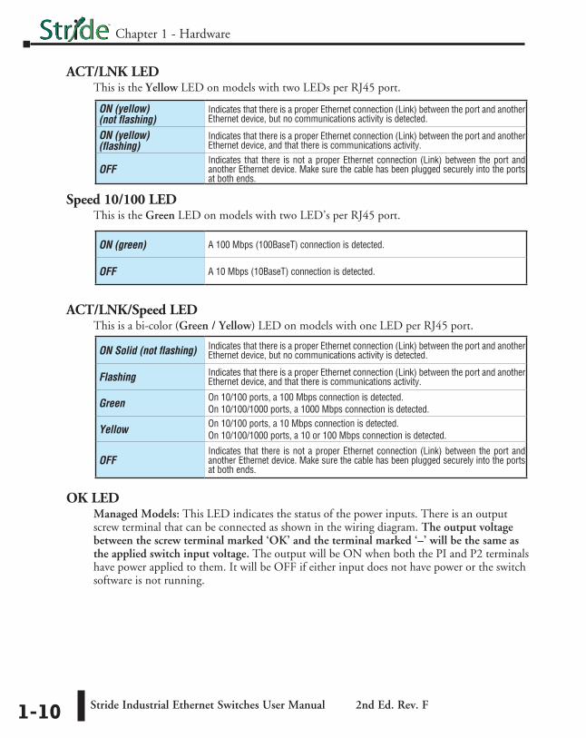
ACT/LNK LEDThis is the Yellow LED on models with two LEDs per RJ45 port.
Speed 10/100 LEDThis is the Green LED on models with two LED’s per RJ45 port.
ACT/LNK/Speed LEDThis is a bi-color (Green / Yellow) LED on models with one LED per RJ45 port.
ON Solid (not flashing) Indicates that there is a proper Ethernet connection (Link) between the port and another Ethernet device, but no communications activity is detected.
Flashing Indicates that there is a proper Ethernet connection (Link) between the port and another Ethernet device, and that there is communications activity.
Green On 10/100 ports, a 100 Mbps connection is detected.On 10/100/1000 ports, a 1000 Mbps connection is detected.
Yellow On 10/100 ports, a 10 Mbps connection is detected.On 10/100/1000 ports, a 10 or 100 Mbps connection is detected.
OFFIndicates that there is not a proper Ethernet connection (Link) between the port and another Ethernet device. Make sure the cable has been plugged securely into the ports at both ends.
OK LEDManaged Models: This LED indicates the status of the power inputs. There is an output screw terminal that can be connected as shown in the wiring diagram. The output voltage between the screw terminal marked ‘OK’ and the terminal marked ‘–’ will be the same as the applied switch input voltage. The output will be ON when both the PI and P2 terminals have power applied to them. It will be OFF if either input does not have power or the switch software is not running.
ON (yellow) (not flashing)
Indicates that there is a proper Ethernet connection (Link) between the port and another Ethernet device, but no communications activity is detected.
ON (yellow) (flashing)
Indicates that there is a proper Ethernet connection (Link) between the port and another Ethernet device, and that there is communications activity.
OFFIndicates that there is not a proper Ethernet connection (Link) between the port and another Ethernet device. Make sure the cable has been plugged securely into the ports at both ends.
ON (green) A 100 Mbps (100BaseT) connection is detected.
OFF A 10 Mbps (10BaseT) connection is detected.

Installation, Plastic Case SwitchesOverview
These industrial Ethernet switches and media converters can be snapped onto a standard 35 mm x 7.5 mm height DIN rail (Standard: CENELEC EN50022). The switches and media converters can be mounted either vertically or horizontally. Refer to the mechanical drawings that follow for proper mounting.
NOTE: Make sure to allow enough room to route your Ethernet copper or fiber optic cables.
DIN Rail MountingDIN rail mounting steps:
1. Hook top back of unit over the DIN rail.
2. Push bottom back onto the DIN rail until it snaps into place.
DIN rail removal steps:A. Insert screwdriver into DIN clip and pry until it releases from the DIN rail.
B. Unhook top of unit from DIN rail.
Mounting Removal
1
2
A
B
Stride Industrial Ethernet Switches User Manual 2nd Ed. Rev. F
Chapter 1 - Hardware
1-11

Stride Industrial Ethernet Switches User Manual 2nd Ed. Rev. F
Chapter 1 - Hardware
Installation, Metal Case SwitchesOverview
These industrial Ethernet switches can be snapped onto a standard 35 mm x 7.5 mm height DIN rail (Standard: CENELEC EN50022). They can be mounted either vertically or horizontally. Refer to the mechanical drawings that follow for proper mounting.
NOTE: Make sure to allow enough room to route your Ethernet copper or fiber optic cables.
DIN Rail MountingDIN rail mounting steps:
1. Hook top back of unit over the DIN rail.
2. Push bottom back onto the DIN rail until it snaps into place.
DIN rail removal steps:A. Push the unit down to free the bottom of the DIN rail.
B. Rotate the bottom of the unit away from the DIN rail.
C. Unhook top of unit from DIN rail.
Mounting
1
2
A
B
Removal
C
1-12

Mounting OptionsStride switches with metal cases offer the following optional mounting methods.
A. Vertical DIN rail mount.This mounting option allows for quickest installation and optimal utilization of rail space.
B. Vertical screw to panel mount.This mounting option gives better shock and vibration resistance.
C. Flat screw to panel mount.This mounting option offers a low profile orientation in shallow boxes plus the best shock and vibration resistance. The power connection terminal block is removable for access to the mounting tab.
Important Notes about Thermal PerformanceStride switches with metal cases use an innovative technique to remove excess heat from the product and its components. This technique effectively utilizes the heavy gauge all-aluminum case as a large heat sink. Therefore, the case may be warm during operation, especially with heavy loads such as all ports linked and active. This is normal operation. For best performance, it is recommended that a DIN rail spacer such as end clamp, part number DN-EB35, be used between the switch and any adjacent device. This will leave an air gap for best heat dissipation off the case.
For best thermal performance when direct panel mounting to a metal surface, thermal compound may be used between the switch and mounting surface. This will reduce any air gaps and optimize the transfer of heat from the case to the mounting surface.
A B C
Stride Industrial Ethernet Switches User Manual 2nd Ed. Rev. F
Chapter 1 - Hardware
1-13

Stride Industrial Ethernet Switches User Manual 2nd Ed. Rev. F
Chapter 1 - Hardware
Mechanical Dimensions for 5 and 8-Port Unmanaged Models in Plastic Case
Inches [mm]
Mechanical Dimensions for 5 and 9-Port Unmanaged Models with Fiber in Plastic CaseInches [mm]
5 Port 9 Port
3.96 [100.6]
1.00 [25.4]
4.35 [110.5]
1.50 [38.1]
Dia. 0.15 [3.8] Use for direct
panel mounting to a flat surface.
1.98[50.3]
3.26 [82.8]
0.06 [1.5]
0.40 [10.2]
1.98[50.3]
Snaps to standard 35 mm x 7.5 mm height
DIN rail (EN50022)
Removable Screw Block,
Phoenix p/n 1757035
SE-SW5U-ST, SE-SW5U-SCSE-SW9U-ST and SE-SW9U-SC
1.01[25.7]
1.01[25.7]
1-14
5 Port 8 Port
3.95[100.3]
1.00 [25.4]
4.20[106.7]
1.50 [38.1]
Dia. 0.15 [3.8] Use for direct
panel mounting to a flat surface.
1.98[50.3]
3.26 [82.8]
0.06 [1.5]
Snaps to standard 35 mm x 7.5 mm height
DIN rail (EN50022)
1.98[50.3]
Removable Screw Block,
Phoenix p/n 1757035
1.01[25.7]
1.01[25.7]
5 or 8 Port – SE-SW5U & SE-SW8U

Stride Industrial Ethernet Switches User Manual 2nd Ed. Rev. F
Chapter 1 - Hardware
Mechanical Dimensions for 2-Port Media Converter in Plastic Case
Inches [mm]
Mechanical Dimensions for 5 and 8-Port Unmanaged Models in Metal Case
Inches [mm]
1-15
3.96 [100.6]
1.00 [25.4]
Removable Screw Block,
Phoenix p/n 1757035
Media Converters – SE-MC2U-ST and SE-MC2U-SC
Dia. 0.15 [3.8] Use for direct
panel mounting to a flat surface.
3.26 [82.8]
0.06 [1.5]
0.40 [10.2]
Snaps to standard 35 mm x 7.5 mm height
DIN rail (EN50022)
4.35 [110.5]
1.98[50.3]
1.98[50.3]
1.01[25.7]
1.01[25.7]
Snaps to standard35 mm x 7.5 mm height
DIN rail (EN50022)
RemovableScrew Block,
Phoenixp/n 1757035
C
2.25[57.1]
2.25[57.1]
Dia. 0.175 [4.4]Use for direct
panel mounting toa flat surface withup to #8 screw.
0.175[4.4]
4.50[114.3]
4.00[101.6]
0.30[7.6]
1.10[27.9]
4.35[110.5]
Removablefor direct panel
mounting
1.50[3.81]
0.55[14.0]
1.60[40.6]
5 Port 8 Port
0.80[20.3]
3.00[76.2]
0.39[9.9]
5 or 8 Port – SE-SW5U-WT & SE-SW8U-WT

Mechanical Dimensions for 5 and 9-Port Unmanaged Models with Fiber in Metal CaseInches [mm]
Snaps to standard35 mm x 7.5 mm height
DIN rail (EN50022)
RemovableScrew Block,
Phoenixp/n 1757035
C
2.25[57.1]
2.25[57.1]
0.40[10.2]
Dia. 0.175 [4.4]Use for direct
panel mounting toa flat surface withup to #8 screw.
0.175[4.4]
4.50[114.3]
4.00[101.6]
0.30[7.6]
1.10[27.9]
4.35[110.5]
Removablefor direct panel
mounting
1.50[3.81]
0.55[14.0]
1.60[40.6]
5 Port 9 Port
0.80[20.3]
3.00[76.2]
0.39[9.9]
SE-SW5U-ST-WT, SE-SW5U-SC-WTSE-SW9U-ST-WT and SE-SW9U-SC-WT
Stride Industrial Ethernet Switches User Manual 2nd Ed. Rev. F
Chapter 1 - Hardware
1-16

Stride Industrial Ethernet Switches User Manual 2nd Ed. Rev. F
Chapter 1 - Hardware
Mechanical Dimensions for 5-Port Managed ModelInches [mm]
1-17
SE-SW5M

Mechanical Dimensions for 5-Port Managed Models with FiberInches [mm]
SE-SW5M-2ST and SE-SW5M-2SC
1-18
Chapter 1 - Hardware
Stride Industrial Ethernet Switches User Manual 2nd Ed. Rev. F

Mechanical Dimensions for 8-Port Managed ModelInches [mm]
SE-SW8M
1-19
Chapter 1 - Hardware
Stride Industrial Ethernet Switches User Manual 2nd Ed. Rev. F

Mechanical Dimensions for 8-Port Managed Models with FiberInches [mm]
SE-SW8M-2ST and SE-SW8M-2SC
1-20
Chapter 1 - Hardware
Stride Industrial Ethernet Switches User Manual 2nd Ed. Rev. F

Mechanical Dimensions for 8-Port Managed Gigabit Switch with Four SFP PortsInches [mm] SE-SW8MG-4P
1-21
Chapter 1 - Hardware
Stride Industrial Ethernet Switches User Manual 2nd Ed. Rev. F

Mechanical Dimensions for 10-Port Managed Gigabit Switch with Two SFP PortsInches [mm]
SE-SW10MG-2P
1-22
Chapter 1 - Hardware
Stride Industrial Ethernet Switches User Manual 2nd Ed. Rev. F

Mechanical Dimensions for 16-Port Managed ModelInches [mm]
SE-SW16M
1-23
Chapter 1 - Hardware
Stride Industrial Ethernet Switches User Manual 2nd Ed. Rev. F

1-24
Mechanical Dimensions for SFP Transceiver ModulesInches [mm]
Chapter 1 - Hardware
Stride Industrial Ethernet Switches User Manual 2nd Ed. Rev. F
SFP-4K-FMF, SFP-30K-FSF, SFP-500-GMF, SFP-2K-GMF, SFP-10K-GSF and SFP-30K-GSF

1-25
Power and Alarm WiringOverview
DC voltage in the range of 10 to 30 VDC (3.0W) needs to be applied between the P1 (plus) terminal and the Minus terminal as shown below. To maintain a UL 508 panel listing use a Class 2 power supply. The chassis screw terminal should be tied to panel or chassis ground. To reduce down time resulting from power loss, these industrial Ethernet switches can be powered redundantly with a second power supply as shown below.
NOTE: When powering multiple switches from a common power supply, it is most reliable to power the switches sequentially rather than simultaneously. The characteristics of the power supply and the significant startup current of the switches may result in an error in booting the switches when powered simultaneously.
Screw TorqueWhen tightening the screws be careful to tighten to a max. torque of 5 lb-in [0.57 Nm]. Wire size should be between 24 AWG and 12 AWG.
Before performing any wiring to these switches make sure... • The area is currently nonhazardous (especially when working in Class 1, Div 2 or Zone 2 hazardous locations). • Power is off to the switch • The screw terminal block is unplugged. This is especially important on the aluminum housed units as shown below. Connecting or disconnecting wires to the screw block when its in place and power is turned on can allow the screwdriver to short the power to the case
Unmanaged Models:
One DC Supply
+ –
P2 P1
Single DC Power Redundant DC Power
Chassis GND
(panel) + – + – Chassis
GND (panel)
Dual DC Supplies
P2 P1
Managed Models:SE-SW5M, SE-SW5M-2ST, SE-SW5M-2SC, SE-SW8M, SE-SW8M-2ST and SE-SW8M-2SC
OK P2
One DC Supply
+ –
ChassisGND
(panel)
P1
ChassisGND
(panel)
Single DC Power Redundant DC Power
+ –+ –
Dual DC Supplies
OK P2 P1
+–
+–
AlarmOutputLoad(opt.)
AlarmOutputLoad(opt.)
Chapter 1 - Hardware
Stride Industrial Ethernet Switches User Manual 2nd Ed. Rev. F

1-26
Managed Models:SE-SW16M and SE-SW10MG-2P
– +
OK P1P2
One DC Supply
ChassisGND
(panel)
Single DC Power Redundant DC Power
– +
Dual DC Supplies
ChassisGND
(panel)
OK P1P2
– +
+–
+–
AlarmOutputLoad(opt.)
AlarmOutputLoad(opt.)
SE-SW8MG-4P
P2P1
One DC Supply
ChassisGND
(panel)
OK
ChassisGND
(panel)
Single DC Power Redundant DC Power
Dual DC Supplies
P2P1 OK
– +– +
– +
+–
+–
AlarmOutputLoad(opt.)
AlarmOutputLoad(opt.)
Chapter 1 - Hardware
Stride Industrial Ethernet Switches User Manual 2nd Ed. Rev. F

Communication Ports WiringOverview
The industrial Ethernet switches and media converters provide connections to standard Ethernet devices such as PLCs, Ethernet I/O, industrial computers and much more. RJ45 (copper) Ethernet ports and fiber optic Ethernet ports are available depending on model.
RJ45 Ethernet WiringUse data-quality (not voice-quality) twisted pair cable rated category 5e (or better) with standard RJ45 connectors. Straight-through or crossover Ethernet cable can be used for all devices the switch is connected to because all the ports are capable of auto-mdi/mdix-crossover detection.
The RJ45 Ethernet port connector bodies on these products are metallic and connected to the Chassis GND terminal. Therefore, shielded cables may be used to provide further protection. To prevent ground loops, the cable shield should be tied to the metal connector body at one end of the cable only. Electrical isolation is also provided on the Ethernet ports for increased reliability.
NOTE: For reference only. Either cable wiring will work.
RJ45 Cable DistanceThe maximum cable length for 10/100BaseT is 100 meters (328 ft.).
81 1
8
Straight-thru Cable Wiring
Pin 1 Pin 1
Pin 2 Pin 2
Pin 3 Pin 3
Pin 4 Pin 4
Pin 5 Pin 5
Pin 6 Pin 6
Pin 7 Pin 7
Pin 8 Pin 8
Cross-over Cable Wiring
Pin 1 Pin 3
Pin 2 Pin 6
Pin 3 Pin 1
Pin 4 Pin 4
Pin 5 Pin 5
Pin 6 Pin 2
Pin 7 Pin 7
Pin 8 Pin 8
Ethernet Plug & Connector Pin Positions
1-27
Chapter 1 - Hardware
Stride Industrial Ethernet Switches User Manual 2nd Ed. Rev. F
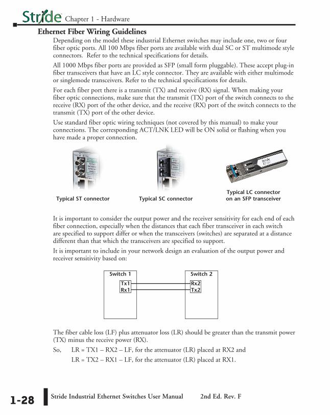
Ethernet Fiber Wiring GuidelinesDepending on the model these industrial Ethernet switches may include one, two or four fiber optic ports. All 100 Mbps fiber ports are available with dual SC or ST multimode style connectors. Refer to the technical specifications for details.
All 1000 Mbps fiber ports are provided as SFP (small form pluggable). These accept plug-in fiber transceivers that have an LC style connector. They are available with either multimode or singlemode transceivers. Refer to the technical specifications for details.
For each fiber port there is a transmit (TX) and receive (RX) signal. When making your fiber optic connections, make sure that the transmit (TX) port of the switch connects to the receive (RX) port of the other device, and the receive (RX) port of the switch connects to the transmit (TX) port of the other device.
Use standard fiber optic wiring techniques (not covered by this manual) to make your connections. The corresponding ACT/LNK LED will be ON solid or flashing when you have made a proper connection.
Typical ST connector Typical SC connectorTypical LC connector on an SFP transceiver
It is important to consider the output power and the receiver sensitivity for each end of each fiber connection, especially when the distances that each fiber transceiver in each switch are specified to support differ or when the transceivers (switches) are separated at a distance different than that which the transceivers are specified to support.
It is important to include in your network design an evaluation of the output power and receiver sensitivity based on:
Switch 1
Tx1Rx1
Switch 2
Rx2Tx2
The fiber cable loss (LF) plus attenuator loss (LR) should be greater than the transmit power (TX) minus the receive power (RX).
So, LR = TX1 – RX2 – LF, for the attenuator (LR) placed at RX2 and
LR = TX2 – RX1 – LF, for the attenuator (LR) placed at RX1.
1-28
Chapter 1 - Hardware
Stride Industrial Ethernet Switches User Manual 2nd Ed. Rev. F

Duplex OperationThe RJ45 ports will auto-sense for Full or Half duplex operation; the fiber ports are configured for full duplex operation. On managed switches the duplex setting is software configurable.
NOTE: Fiber devices with half duplex settings will communicate with the switch in most situations.
Network Device CheckThe industrial Ethernet switches and media converters support 10/100BaseT or 10/100/100 Base T on the RJ45 (copper) ports and 100BaseFX or gigabit Ethernet on the fiber optic ports depending on model. Make sure you connect the appropriate devices to each port.
NOTE: The following AutomationDirect PLC Ethernet Modules are not compatible with the Stride Ethernet switches and Media Converters with fiber optic connections because the modules have a speed of 10BaseF (fiber optic) only: Ethernet Communications Module, p/n H2-ECOM-F & H4-ECOM-F; Ethernet Base Controller Module, p/n H2-EBC-F & H4-EBC-F; Ethernet Remote Master Module, p/n H2-ERM-F & H4-ERM-F.
Verifying ConnectivityAfter all Ethernet and/or fiber connections are made, check the LEDs corresponding to the ports that each of the devices are connected to. Ensure that for each port that is in use, the LED is on or blinking. If a port LED is off, go back and check for connectivity problems between that port and the network device connected to that port. In addition, the color of the LED should indicate the speed at which your device is connected (see prior section on LEDs).
Serial Console Port WiringAn optional way to configure the managed switch is through the RJ45 console RS232 port. Wire a serial console cable as shown below to make a connection between a COM port on your PC (DB9 male) and the RS232 port of the managed switch (RJ45 female).
1-29
Chapter 1 - Hardware
Stride Industrial Ethernet Switches User Manual 2nd Ed. Rev. F
Serial Configuration CableSwitch RJ-45Serial Port
PC Serial Port
6
1 = do not use2 = RXD3 = TXD4 = do not use5 = Signal GND6 = do not use7 = do not use8 = do not use9 = do not use
54
TXD
RXD
GND
235 1
RXD
TXD
shield
Wiring Diagram
Note: Use the above wiring diagram to make your own cable. We recommend using 22 AWG shielded cable.
1 = do not use2 = do not use3 = do not use4 = Signal GND5 = RXD6 = TXD7 = do not use8 = do not use
RJ45 8-pin Phone Plug
(8P8C)
9-pinD-sub
(female)1
9

USB Console Port WiringThe managed switches also have an USB port alternative to the RS232 port. Use a standard USB cable with a mini-USB plug on one end and an A-type-USB plug on the other end. The A-type plug goes into a standard USB port on a computer. The mini-USB plug goes into the USB port on the switch.
The USB driver is available for download at automationdirect.com.
NOTE: The RS-232 and/or USB ports may be located on the bottom edge or front face of the switch.
1-30
Chapter 1 - Hardware
Stride Industrial Ethernet Switches User Manual 2nd Ed. Rev. F
RS232 RJ45F
Mini-USB
RS232 RJ45F
Mini-USB

Technical SpecificationsTechnical Specs
Here are the hardware technical specifications for the industrial Ethernet switches and media converters covered by this manual.
Technical Specifications continued on the next page.
General Specifications
Ethernet switch type Unmanaged or Managed
Operating mode Store & forward, wire speed switching, non-blocking
Devices supported All IEEE 802.3 compliant devices are supported
Protocols (managed models only)
SNMPv1/v2/v3, RMON, DHCP, SNTP, TFTP, STP, RSTP, QoS/CoS/ToS/DS, IGMPv1/v2, VLAN (tag and port based), HTTP, HTTPS (SSL & TSL), Telnet, SSH and more
Industrial Protocols supported Modbus/TCP, EtherNet/IP, PROFInet, Foundation Fieldbus HSE and others
Standards (depends on model) IEEE 802.3, 802.3u, 802.3ab/z, 802.3x, 802.1D/w, 802.1p, 802.1Q and others
Management Interfaces (managed models only)
Web, text (Telnet & SSH), CLI (command lineinterface) and SNMP (see Chapter 2 - Managed Switch Software for supported MIBs)
MAC addresses1024 on unmanaged models;
2048 on managed models with 5, 8 or 9 ports 8192 on Gigabit models with more than 9 ports
Memory bandwidth 3.2 Gbps on models with 9 or fewer ports 3.2 Gbps on models with more than 9 ports
Latency for 10 Mbps ports* 16 us + frame time (typical)
Latency for 100 Mbps ports* < 5 us + frame time (typical)
Ethernet isolation 1500 VRMS 1 minute
Management Serial Port (managed models only) RS232 (TXD, RXD and GND), 9600, 8, N, 1 fixed and/or mini-USB
* Varies on load and settings
1-31
Chapter 1 - Hardware
Stride Industrial Ethernet Switches User Manual 2nd Ed. Rev. F

Technical Specifications (cont’d)
Technical Specifications continued on the next page.
Copper RJ45 Ports: (10/100 Mbps or 10/100/1000 Mbps)
Copper Ports Shielded RJ45
Speed 10/100 Mbps or 10/100/1000 Mbps (depending on model)
Protocols supported All standard IEEE 802.3
Auto-crossover Yes, allows you to use straight-through or crossover wired cables
Auto-sensing operation Yes, Full and half duplex
Auto-negotiating Yes, 10BaseT and 100BaseT
Auto-polarity Yes, on the TD and RD pair
Flow control Automatic
Ethernet isolation 1500 VRMS 1 minute
Plug and play Yes
Cable requirements Twisted pair (Cat. 5 or better) (shielded recommended)
Max. cable distance 100 meters (328 ft)
1-32
Chapter 1 - Hardware
Stride Industrial Ethernet Switches User Manual 2nd Ed. Rev. F

Technical Specifications (cont’d)
NOTE: Refer to SFP module specifications for details specific to the SFP installed.
NOTE: When powering multiple switches from a common power supply, it is most reliable to power the switches sequentially rather than simultaneously. The characteristics of the power supply and the significant startup current of the switches may result in an error in booting the switches when powered simultaneously.
SFP (Small Form Factor pluggable) Ports
Note: On the Gigabit (MG) models these ports are pluggable and accept any SFP Multi-Source Agreement compliant transceiver.
Gigabit SFP ports 2 or 4 depending on model
Port Types Supported All SFP Multi-Source Agreement compliant transceivers
Note: 100 Mbps fiber transceiver modules are also supported on these ports.
Ethernet Compliance 1000BaseT and 1000BaseF (SX/LX/LH)
Eye safety IEC 60825-1, Class 1; FDA 21 CFR 1040.10 and 1040.11
SC or ST Fiber Ports: 100BaseF multimode
100BaseFX ports 1 on some unmanaged switch models 2 on some managed switch models
Fiber port mode Multimode (mm)
Fiber port connector Duplex SC or ST
Optimal fiber cable 50/125 or 62.5/125 µm for mm; 9/125 µm for sm
Center wavelength 1300 nm
MultimodeLinks up to 4 km typ.; 1300 nm; use with 50 or 62.5/125 um fiber
> Transmitter power (dB): -21 min, -17 typ, -14 max > Receiver sensitivity (dB): -34 typ, -31 max
Nominal max. distance (full duplex) (see web for details)
4 km
Half and Full Duplex Full duplex
Ethernet Compliance 100BaseF
Eye Safety IEC 60825-1, Class 1; FDA 21 CFR 1040.10 and 1040.11
1-33
Chapter 1 - Hardware
Stride Industrial Ethernet Switches User Manual 2nd Ed. Rev. F

Stride Industrial Ethernet Switches User Manual 2nd Ed. Rev. F
Chapter 1 - Hardware
Technical Specifications (cont’d)
1-34
“OK” Alarm Output (Managed models only)
“OK” Output ON if P1 and P2 have power and switch software is running
Voltage Same as switch input voltage
Maximum Current Output 0.5 Amp
Power InputPower Input Redundant Input Terminals
Input power (typical withall ports active at 100Mbps)
SE-MC2U-SC - 2.0W SE-MC2U-ST - 2.0W
SE-SW5U - 2.0W SE-SW5U-WT - 2.0W SE-SW5U-SC - 3.0W
SE-SW5U-SC-WT - 3.0W SE-SW5U-ST - 3.0W
SE-SW5U-SC-WT - 3.0W SE-SW8U - 4.0W
SE-SW8U-WT - 4.0W SE-SW9U-SC - 5.0W
SE-SW9U-SC-WT - 5.0W SE-SW9U-ST - 5.0W
SE-SW9U-ST-WT - 5.0W
SE-SW5M - 3.6W SE-SW5M-2SC - 5.6W SE-SW5M-2ST - 5.6W
SE-SW8M - 4.3W SE-SW8M-2SC - 6.3W SE-SW8M-2ST - 6.3W
SE-SW8MG-4P - 12.0W - No Fiber SE-SW8MG-4P - 15.0W - With 4 Fiber plugged in
SE-SW10MG-2P - 5.0W - No Fiber SE-SW10MG-2P - 7.0W - With 4 Fiber plugged in
SE-SW16M - 7.0W
Input Voltage (all models) 10-30 VDC (continuous)
Reverse Power Protection Yes
Transient Protection 15,000 watts peak
Spike Protection 5,000 watts (10x for 10 uS)

Stride Industrial Ethernet Switches User Manual 2nd Ed. Rev. F
Technical Specifications (cont’d)
1-35
Mechanical
Ingress Protection IP30 for all plastic cased units. IP40 for all metal cased units.
Packaging and Protection UL94V0 Lexan plastic for all plastic cased units. Aluminum w/ protective finish for all metal cased units.
Dimensions (L x W x H) See mechanical drawings for details
Environmental
Storage Temperature Range -40 to +85 °C (-40 to +185 °F)
Humidity (non-condensing) 5 to 95% RH
Electrical Safety UL508/CSA C22, EN61010-1, CE
EMC: emissions and immunity
FCC part 15, ICES-003; EN61000-6-2, EN61000-6-4 Typical 8 or 9/125 µm for singlemode (sm)
Hazardous Locations UL HazLoc, CSA C22.2/213 (Class I, Div.2) ; EN60079-15 (Zone2), CE (ATEX)
Eye Safety (fiber models) IEC60825-1, Class 1; FDA 21 CFR 1040.10 and 1040.11
RoHS and WEEE RoHS (Pb free) and WEEE compliant
ISO9001:2000 Certified “Total Quality” company