Embed Size (px)
Citation preview

SCHULTZ ASSOCIATES FEA results for CARMA bases for6 meter BIMA antennas Page 1 of 8
Figure 1 BIMA 6 Meter antenna sittingon new CARMA base
Max Von Mises Stress S.F.
Case Condition psi W/R yield
A1 E'xporter stop going down = 2G 13,490 2.67
B1 E'xporter stops going west = 1G 20,500 1.76
B2 E'xporter stops going east = 1G 26,200 1.37 local hot spots w ill yield and spread load
B3 E'xporter stops going south = 1G 34,600 1.04
C1 100MPH wind West 8,100 4.44
C2 100MPH wind East 8,200 4.39
C3 100MPH wind South 9,900 3.64
C4 100MPH wind South-East 5,400 6.67
Figure 2 Tabulated stress results and safety factors W/R A36 steel yield
Stress and Deflection FEA of CARMA Mounts for BIMA ANTENNAS
Thursday, April 7, 2005
This is a report containing the results of analysis performedby SCHULTZ ASSOCIATES for the University ofCalifornia Radio Astronomy Laboratory under P.O. 1-0000991716, Rev. N/C. Load cases and general guidelines were provided in a memo entitled Proposal for FEAFinite Element Analysis on new antenna base, datedThursday, December 02, 2004. Analytic methods aredescribed below in section called SUMMARY OFANALYSIS.
SUMMARY OF RESULTS:
STRESS: Transporter loads and survival loading at 100MPH wind at all specified orientations produces stress inthe weldment that are below the yield strength of commonASTM A36 steel. The table below shows the peak stressand safety factor with respect to A36 yield strength for allstress load cases, A1through C4.
The highest stressesseen in the model occurin the shank of thethree jacks. The jacksare not modeled tocheck their adequacybut are modeled toshow the operating andhandling stress in theweldment.
Transportation generally causes more stress than wind survival at 100 MPH.
DEFLECTION: Overturning angular deflection at worst case orientation 30 MPH wind peaks atabout 5 arc seconds and averages 3 arc seconds RMS’ed spatially among all the wind orientations.Torsional rotations (Azimuth) will be smaller.

SCHULTZ ASSOCIATES FEA results for CARMA bases for6 meter BIMA antennas Page 2 of 8
Figure 3 Case A1 crude results with bad element aspect ratios
SUMMARY OF ANALYSIS:
Meshing:
The model provided included a device above the new base that would spread the applied loads to thebase. First meshing and analysis was conducted this way. however, the load spreader added far toomany elements to the FEA model as is shown below in Fig. 3.
Default global mesh size of 2.75" produced a 422 thousand degree of freedom (kdof) model that runs

SCHULTZ ASSOCIATES FEA results for CARMA bases for6 meter BIMA antennas Page 3 of 8
Figure 4 Combined stress due to 2G’s downward load in transporter Case A1
Figure 5 Combined stress due to transporter stop going West, Case B1
fast but mesh element aspect ratio is 2.75/.25=11, not good for study accuracy. This ratio should beno higher than 3 for accurate results. See crude initial results. Later accurate results are significantlydifferent. This ratio was reduced to 3 by deleting the load application part and applying the loads toeach of the three mounting points as assessed by calculation. Appendix A contains MathCADgenerated calculations where each load case is resolved to three point loading at the top of the newbase structure.
There are many orientations of the reflector and winds. Calculation of all of them severely exceedsthe practical expectations of the funding of this effort. Simplification was conservatively achievedby selecting the worst wind loads irrespective of orientation and simultaneously applying them to themodel. If these deflections are acceptable to the operation of the antennas, well and good. If not,resources can be allocated to analysis of several representative cases to assess the more accurateworst case pointing error or be spatially averaged to arrive at a more favorable statistical pointingerror.
DETAILED RESULTS:
A1, Antenna assembly mounted on new structure that is lifted by the transporter and then lowered
SCHULTZ ASSOCIATES FEA results for CARMA bases for6 meter BIMA antennas Page 4 of 8
Figure 6 Antenna assembly on transporter going West stopping abruptly causing 1G loading, CaseB1
and the lowering stops abruptly, as can happen when the lifting control stops this motion carelesslyor the load is dropped on the ground. Fig 4 shows the Von Messis (combined) stress distribution onthe weldment surface due to this loading. This and all the stress figures are static in this document.However, they can be dynamically viewed by means of using a viewer to display eDrawing files(*.eprt) of these figures.
B1, Antenna assembly mounted on the new structure that is transported West and stopped abruptlysuch that 1G is required to decelerate the load. Maximum stress on weldment is 20,500 psi. near topof West mounting hole.

SCHULTZ ASSOCIATES FEA results for CARMA bases for6 meter BIMA antennas Page 5 of 8
Figure 7 Antenna assembly going East on transporter stopping abruptlycausing 1G loads, Case B2
Figure 8 Antenna assembly going South on transporter stopping abruptlycausing 1G loads, Case B3
B 2 , A n t e n n aa s s e m b l y i smounted on thenew base that istransported Easta n d s t o p p e dabruptly such that1G is required todecelerate the load.Maximum stress onweldment is 26,200psi near the top ofthe North andSouth mountingholes.
B3, Antenna assembly is mounted on the new base that is transported South and stopped abruptlysuch that 1G is required to decelerate the load. Maximum combined stress on the weldment is 34,600
psi, nearly equal tothe specified yield ofA36 plate.
This is the mostsevere stress seen inall the cases. It isonly seen at a smallportion of the 1/4"side plates in theupper right of Fig. 8.

SCHULTZ ASSOCIATES FEA results for CARMA bases for6 meter BIMA antennas Page 6 of 8
Figure 9 Case C1, 100 MPH wing, worst orientations
Figure 10 Case C2, 100 MPH wind, worst orientations
C1, Antenna assembly is mounted to the new base. The base is tied down to a foundation and it’sjacks also rest on the foundation. Survival wind blows 100 MPH from the West. The dead weightof the antennaassembly shiftsdown wind tothe North andSouth postswhich show thelargest stressesthat peak at8 , 1 0 0 p s icombined stress.
C2, Antenna isas above butthe survivalwind is goingEast. The deadweight of thea n t e n n aassembly shiftsto the East postw h e r ecombined stresspeaks at 8,200psi

SCHULTZ ASSOCIATES FEA results for CARMA bases for6 meter BIMA antennas Page 7 of 8
Figure 11 Case C3, 100 MPH wind, worst orientations
Figure 12 Case C4, 100 MPH wind, worst orientations
C3, Antennais as abovebut wind isf r o m t h eSouth. Theantenna deadweight shiftstoward theNorth postw h e r ec o m b i n e dstress rises to9,900 psi.
C4, Antennais as abovebut wind isf r o m t h eSouth-East .The antennadead weight isshifted to theW e s t a n dNorth postwhere thec o m b i n e dstress peaks at5,400 psi.
SCHULTZ ASSOCIATES FEA results for CARMA bases for6 meter BIMA antennas Page 8 of 8
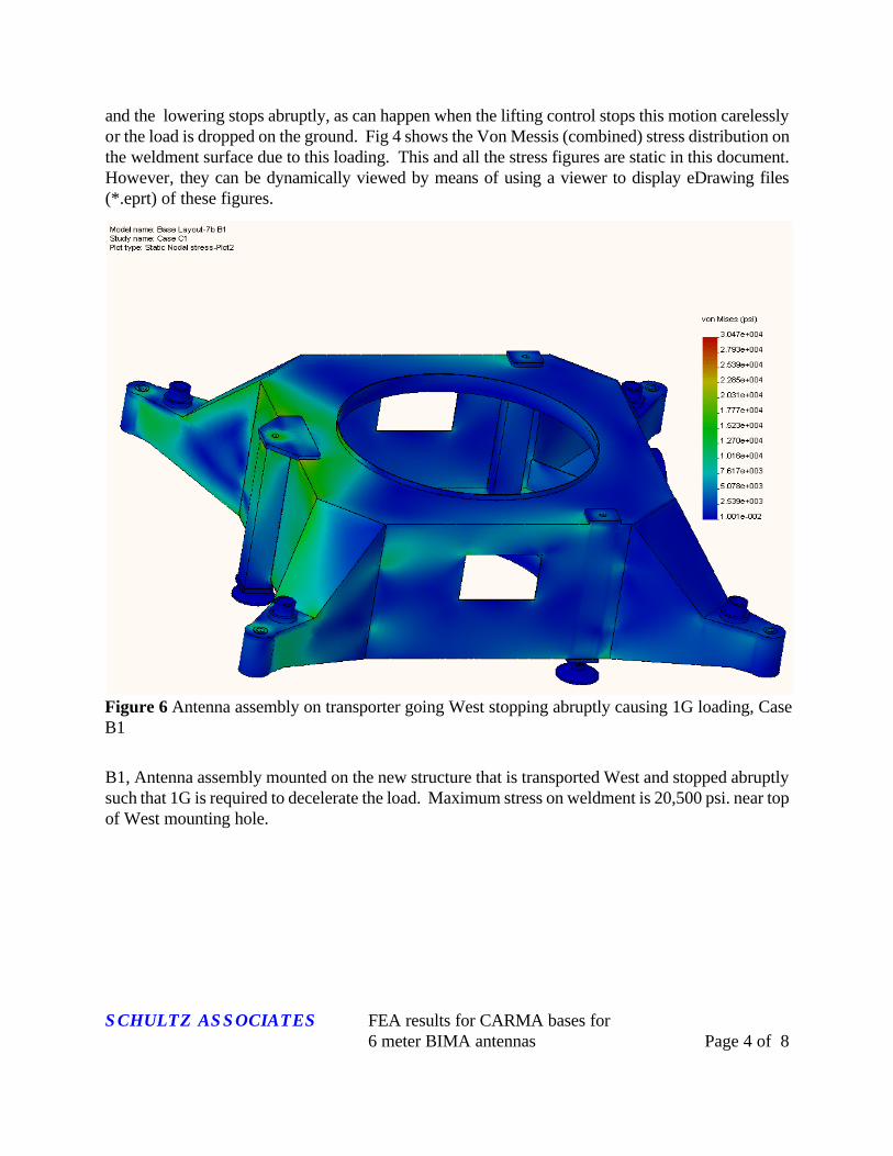
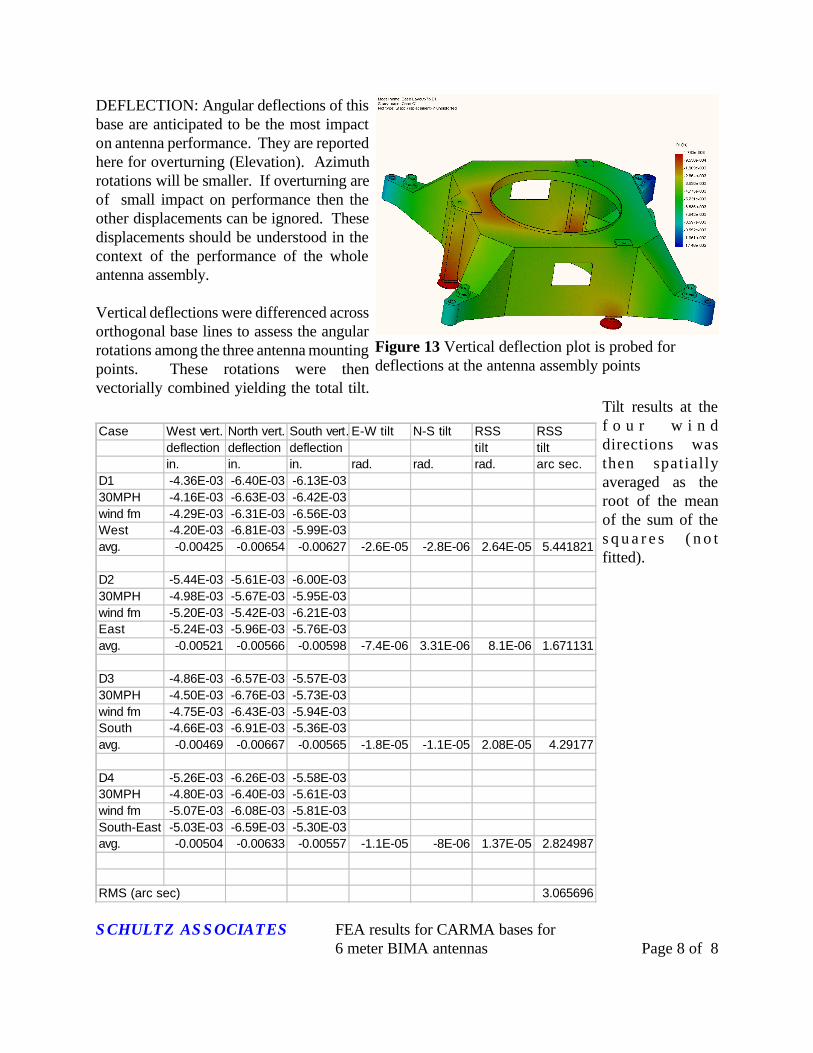
Figure 13 Vertical deflection plot is probed fordeflections at the antenna assembly points
Case West vert. North vert. South vert. E-W tilt N-S tilt RSS RSSdeflection deflection deflection tilt tiltin. in. in. rad. rad. rad. arc sec.
D1 -4.36E-03 -6.40E-03 -6.13E-0330MPH -4.16E-03 -6.63E-03 -6.42E-03wind fm -4.29E-03 -6.31E-03 -6.56E-03West -4.20E-03 -6.81E-03 -5.99E-03avg. -0.00425 -0.00654 -0.00627 -2.6E-05 -2.8E-06 2.64E-05 5.441821
D2 -5.44E-03 -5.61E-03 -6.00E-0330MPH -4.98E-03 -5.67E-03 -5.95E-03wind fm -5.20E-03 -5.42E-03 -6.21E-03East -5.24E-03 -5.96E-03 -5.76E-03avg. -0.00521 -0.00566 -0.00598 -7.4E-06 3.31E-06 8.1E-06 1.671131
D3 -4.86E-03 -6.57E-03 -5.57E-0330MPH -4.50E-03 -6.76E-03 -5.73E-03wind fm -4.75E-03 -6.43E-03 -5.94E-03South -4.66E-03 -6.91E-03 -5.36E-03avg. -0.00469 -0.00667 -0.00565 -1.8E-05 -1.1E-05 2.08E-05 4.29177
D4 -5.26E-03 -6.26E-03 -5.58E-0330MPH -4.80E-03 -6.40E-03 -5.61E-03wind fm -5.07E-03 -6.08E-03 -5.81E-03South-East -5.03E-03 -6.59E-03 -5.30E-03avg. -0.00504 -0.00633 -0.00557 -1.1E-05 -8E-06 1.37E-05 2.824987
RMS (arc sec) 3.065696
DEFLECTION: Angular deflections of thisbase are anticipated to be the most impacton antenna performance. They are reportedhere for overturning (Elevation). Azimuthrotations will be smaller. If overturning areof small impact on performance then theother displacements can be ignored. Thesedisplacements should be understood in thecontext of the performance of the wholeantenna assembly.
Vertical deflections were differenced acrossorthogonal base lines to assess the angularrotations among the three antenna mountingpoints. These rotations were thenvectorially combined yielding the total tilt.
Tilt results at thef o u r w i n ddirections wasthen spatiallyaveraged as theroot of the meanof the sum of thes q u a r e s ( n o tfitted).