Embed Size (px)
Citation preview

TECHNICAL SESSION 3
Strengthening, Repair & Rehabilitation
The Post-Tensioning Column Repair of High Level Approaches of Sunshine Skyway Bridge in Florida
Teddy Theryo, P.E. Pepe Garcia, P.E. Technical Manager District Structures & Facilities Eng. Parsons Brinckerhoff Florida Dep. Of Transportation 5405 West Cypress St.,Ste.300 2916 Leslie Road MS7-1270 Tampa, Florida 33607 Tampa, Florida 33619
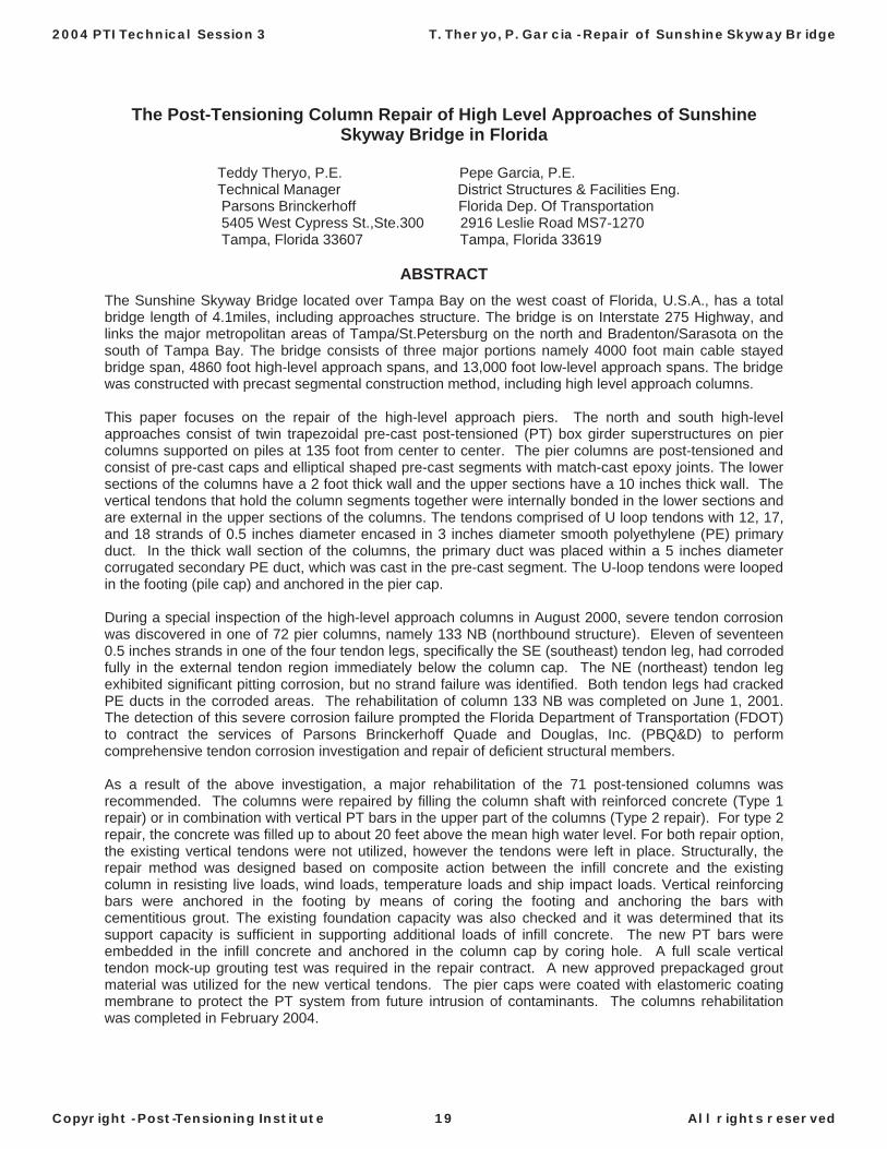
ABSTRACT The Sunshine Skyway Bridge located over Tampa Bay on the west coast of Florida, U.S.A., has a total bridge length of 4.1miles, including approaches structure. The bridge is on Interstate 275 Highway, and links the major metropolitan areas of Tampa/St.Petersburg on the north and Bradenton/Sarasota on the south of Tampa Bay. The bridge consists of three major portions namely 4000 foot main cable stayed bridge span, 4860 foot high-level approach spans, and 13,000 foot low-level approach spans. The bridge was constructed with precast segmental construction method, including high level approach columns.
This paper focuses on the repair of the high-level approach piers. The north and south high-level approaches consist of twin trapezoidal pre-cast post-tensioned (PT) box girder superstructures on pier columns supported on piles at 135 foot from center to center. The pier columns are post-tensioned and consist of pre-cast caps and elliptical shaped pre-cast segments with match-cast epoxy joints. The lower sections of the columns have a 2 foot thick wall and the upper sections have a 10 inches thick wall. The vertical tendons that hold the column segments together were internally bonded in the lower sections and are external in the upper sections of the columns. The tendons comprised of U loop tendons with 12, 17, and 18 strands of 0.5 inches diameter encased in 3 inches diameter smooth polyethylene (PE) primary duct. In the thick wall section of the columns, the primary duct was placed within a 5 inches diameter corrugated secondary PE duct, which was cast in the pre-cast segment. The U-loop tendons were looped in the footing (pile cap) and anchored in the pier cap.
During a special inspection of the high-level approach columns in August 2000, severe tendon corrosion was discovered in one of 72 pier columns, namely 133 NB (northbound structure). Eleven of seventeen 0.5 inches strands in one of the four tendon legs, specifically the SE (southeast) tendon leg, had corroded fully in the external tendon region immediately below the column cap. The NE (northeast) tendon leg exhibited significant pitting corrosion, but no strand failure was identified. Both tendon legs had cracked PE ducts in the corroded areas. The rehabilitation of column 133 NB was completed on June 1, 2001. The detection of this severe corrosion failure prompted the Florida Department of Transportation (FDOT) to contract the services of Parsons Brinckerhoff Quade and Douglas, Inc. (PBQ&D) to perform comprehensive tendon corrosion investigation and repair of deficient structural members.
As a result of the above investigation, a major rehabilitation of the 71 post-tensioned columns was recommended. The columns were repaired by filling the column shaft with reinforced concrete (Type 1 repair) or in combination with vertical PT bars in the upper part of the columns (Type 2 repair). For type 2 repair, the concrete was filled up to about 20 feet above the mean high water level. For both repair option, the existing vertical tendons were not utilized, however the tendons were left in place. Structurally, the repair method was designed based on composite action between the infill concrete and the existing column in resisting live loads, wind loads, temperature loads and ship impact loads. Vertical reinforcing bars were anchored in the footing by means of coring the footing and anchoring the bars with cementitious grout. The existing foundation capacity was also checked and it was determined that its support capacity is sufficient in supporting additional loads of infill concrete. The new PT bars were embedded in the infill concrete and anchored in the column cap by coring hole. A full scale vertical tendon mock-up grouting test was required in the repair contract. A new approved prepackaged grout material was utilized for the new vertical tendons. The pier caps were coated with elastomeric coating membrane to protect the PT system from future intrusion of contaminants. The columns rehabilitation was completed in February 2004.
2004 PTI Technical Session 3 T. Theryo, P. Garcia - Repair of Sunshine Skyway Bridge
Copyright - Post-Tensioning Institute 19 All rights reserved

Engineering for Post-Tensioning Strengthening of Preheater TowerDr. Ralph G. Oesterle, P.E., S.E.
Senior Principal Structural Engineer Construction Technology Laboratories, Inc.
5400 Old Orchard Road Skokie, IL 60077 (P) 847.972.3216 (F) 847.965.6541
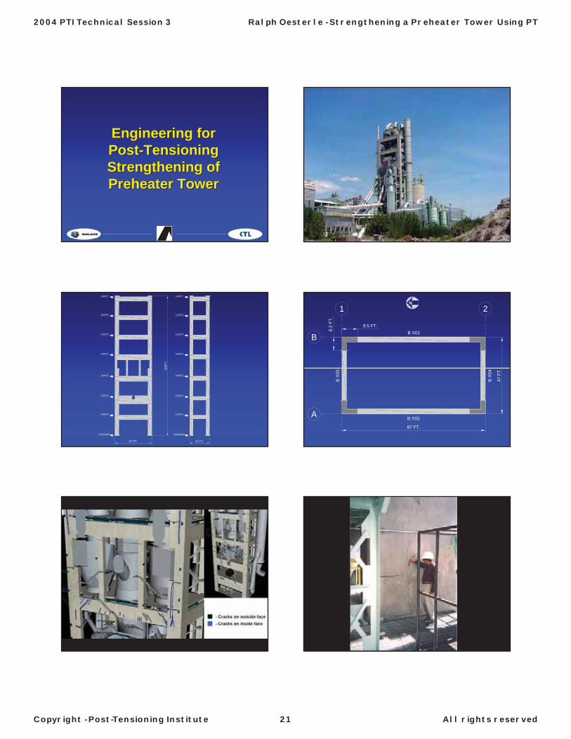
Inspection by plant personnel revealed cracking in the concrete frame of a 326-ft-tall, 7-level preheater tower. On-site plant engineers deemed the cracking significant, especially since the structure supports critical manufacturing process equipment. A structural engineering consulting firm was retained to evaluate the extent of the problem and formulate a repair plan on a fast-track basis. The firm mobilized at the site in less than 24 hours and performed an initial structural safety assessment. A comprehensive condition survey and structural evaluation indicated that all levels of the structure required strengthening.
Restoration consultants were engaged to assist locally with engineering and construction administration. A specialty repair contractor also was engaged to review the constructibility of several alternate repair schemes and maintain the fast-track schedule.
After considering structural capacity and serviceability requirements, durability issues, the high-temperature operating environment, constructibility, and an aggressive construction schedule, the team recommended a retrofit consisting of bonded post-tensioning within internal holes drilled in the beams. This solution was quite extraordinary, as it required precision-drilling horizontal holes up to 87 ft long in the beams of the elevated frame structure, without cutting existing embedded reinforcement.
Nondestructive impulse radar testing was used to locate existing embedded reinforcing steel, as well as to monitor the drilled holes’ trajectory. This process helped ensure proper tendon alignment and prevent damage to embedded steel. The cored holes served as post-tensioning ducts.
The repairs were executed on a fast track and under challenging circumstances, which included working high on the exposed structure through a cold winter with severe wind conditions. The unique retrofit resulted in a structure that is stronger, more serviceable, and more durable than the original tower. The project represented an exceptional team effort, and its success is attributable to the leadership of the owner and client, the ingenuity of the engineering team, and the resourcefulness of the contractor.
This presentation describes the engineering effort required for the strengthening work including the condition survey, structural evaluation, retrofit concept evaluations, retrofit design, and engineering support for the retrofit work. This presentation is intended to be given in conjunction with a presentation by Structural Preservations Systems, Inc. regarding the retrofit construction.
2004 PTI Technical Session 3 Ralph Oesterle - Strengthening a Preheater Tower Using PT
Copyright - Post-Tensioning Institute 20 All rights reserved
Engineering forEngineering forPostPost--TensioningTensioningStrengthening of Strengthening of PreheaterPreheater TowerTower
47 FT.
Level 7
Level 6
Level 5
Level 4
Level 2
Level 1
Top/Grade
Level 3
Level 7
Level 6
Level 5
Level 4
Level 2
Level 1
Top/Grade
Level 3
87 FT.
320F
T.
B
A
1 2
47 F
T.
87 FT.
B X01B
X03
9.5 FT.8.
2 FT
.
B X
04
B X02
N
2004 PTI Technical Session 3 Ralph Oesterle - Strengthening a Preheater Tower Using PT
Copyright - Post-Tensioning Institute 21 All rights reserved
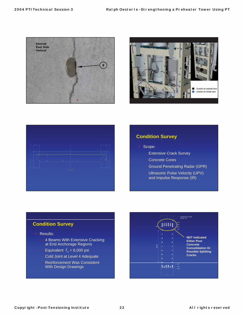
Condition SurveyCondition Survey
•• Scope:Scope:
–– Extensive Crack SurveyExtensive Crack Survey
–– Concrete CoresConcrete Cores
–– Ground Penetrating Radar (GPR)Ground Penetrating Radar (GPR)
–– Ultrasonic Pulse Velocity (UPV) Ultrasonic Pulse Velocity (UPV) and Impulse Response (IR)and Impulse Response (IR)
Condition SurveyCondition Survey
•• Results:Results:–– 4 Beams With Extensive Cracking 4 Beams With Extensive Cracking
at End Anchorage Regionsat End Anchorage Regions–– EquivalentEquivalent ff''cc = 6,000 = 6,000 psipsi–– Cold Joint at Level 4 AdequateCold Joint at Level 4 Adequate–– Reinforcement Was Consistent Reinforcement Was Consistent
With Design DrawingsWith Design Drawings
#8 E
F
NDT Indicated NDT Indicated Either Poor Either Poor Concrete Concrete Consolidation Or Consolidation Or Possible Splitting Possible Splitting CracksCracks
2004 PTI Technical Session 3 Ralph Oesterle - Strengthening a Preheater Tower Using PT
Copyright - Post-Tensioning Institute 22 All rights reserved

Structural EvaluationStructural Evaluation
•• Scope:Scope:
–– Reviewed Design CriteriaReviewed Design Criteria
Wind Load/Seismic LoadWind Load/Seismic Load
Thermal LoadThermal Load
Load CombinationsLoad Combinations
–– Reviewed Original Computer ModelReviewed Original Computer Model
–– Checked Reinforcement DetailsChecked Reinforcement Details
Structural EvaluationStructural Evaluation
•• Scope:Scope:
–– Analyses for Gravity, Thermal and Analyses for Gravity, Thermal and Lateral LoadsLateral Loads
BeamsBeams
ColumnsColumns
DiaphragmsDiaphragms
FoundationsFoundations
Structural EvaluationStructural Evaluation
•• End Anchorage Requirements for End Anchorage Requirements for Flexural ReinforcementFlexural Reinforcement
–– Local or Global Problem?Local or Global Problem?
Structural EvaluationStructural Evaluation
•• Results:Results:
–– All End Regions of All Beams at All End Regions of All Beams at All Levels Required StrengtheningAll Levels Required Strengthening
47 FT.
Wind LoadWind Load
Structural EvaluationStructural Evaluation
•• ResultsResults–– BeamsBeams –– Flexure and ShearFlexure and Shear–– ColumnsColumns
Flexure and AxialFlexure and AxialShearShear
–– Beam/Column Joint Beam/Column Joint –– ShearShear–– DiaphragmsDiaphragms –– Connection to FrameConnection to Frame–– FoundationFoundation –– Pile CapacityPile Capacity
2004 PTI Technical Session 3 Ralph Oesterle - Strengthening a Preheater Tower Using PT
Copyright - Post-Tensioning Institute 23 All rights reserved

Retrofit Concept EvaluationRetrofit Concept Evaluation
•• Beam/Joint Flexural StrengtheningBeam/Joint Flexural Strengthening–– Requirements:Requirements:
Control of CrackingControl of CrackingSense of SafetySense of SafetyLong Term ConfidenceLong Term ConfidenceHigh Temperature EnvironmentHigh Temperature EnvironmentConstructibilityConstructibilityAggressive Construction ScheduleAggressive Construction Schedule
Retrofit Concrete EvaluationRetrofit Concrete Evaluation
•• Early Concepts:Early Concepts:
–– UnbondedUnbonded External PostExternal Post--TensioningTensioning
–– Local PostLocal Post--Tensioning Across Column Tensioning Across Column Above and Below BeamsAbove and Below Beams
–– King Post Truss SystemKing Post Truss System
–– Bonded External PostBonded External Post--TensioningTensioning
–– External PlatesExternal Plates
Retrofit Concept EvaluationRetrofit Concept Evaluation
•• UnbondedUnbonded ExternalExternal
–– PostPost--tensioningtensioning
ConstructibilityConstructibility and Time to Installand Time to Install
Required PostRequired Post--TensioningTensioning
Crack ControlCrack Control
Temperature ProtectionTemperature Protection
Retrofit Concepts EvaluationRetrofit Concepts Evaluation
•• Bonded External PostBonded External Post--TensioningTensioning
2004 PTI Technical Session 3 Ralph Oesterle - Strengthening a Preheater Tower Using PT
Copyright - Post-Tensioning Institute 24 All rights reserved

Retrofit Design Requirements Retrofit Design Requirements for Internal Postfor Internal Post--TensioningTensioning•• Design for Full StrengthDesign for Full Strength
•• Utilize Existing Rebar for Crack ControlUtilize Existing Rebar for Crack Control
•• Thermal AnalysesThermal Analyses
•• Strength Reductions for Long Term Strength Reductions for Long Term Temperature EffectsTemperature Effects
•• Increased Creep and ShrinkageIncreased Creep and Shrinkage
Other Retrofit IssuesOther Retrofit Issues
•• Beam/Column Joint ShearBeam/Column Joint Shear
•• Column ShearColumn Shear
•• Column Axial LoadColumn Axial Load
•• Beam B302Beam B302
•• Epoxy InjectionEpoxy Injection
•• DiaphragmsDiaphragms
•• FoundationsFoundations
2004 PTI Technical Session 3 Ralph Oesterle - Strengthening a Preheater Tower Using PT
Copyright - Post-Tensioning Institute 25 All rights reserved

Other Retrofit IssuesOther Retrofit Issues
•• Beam/Column Joint ShearBeam/Column Joint Shear
•• Column ShearColumn Shear
•• Column Axial LoadColumn Axial Load
•• Beam B302Beam B302
•• Epoxy InjectionEpoxy Injection
•• DiaphragmsDiaphragms
•• FoundationsFoundations
Other Retrofit IssuesOther Retrofit Issues
•• Beam/Column Joint ShearBeam/Column Joint Shear
•• Column ShearColumn Shear
•• Column Axial LoadColumn Axial Load
•• Beam B302Beam B302
•• Epoxy InjectionEpoxy Injection
•• DiaphragmsDiaphragms
•• FoundationsFoundations
Other Retrofit IssuesOther Retrofit Issues
•• Beam/Column Joint ShearBeam/Column Joint Shear
•• Column ShearColumn Shear
•• Column Axial LoadColumn Axial Load
•• Beam B302Beam B302
•• Epoxy InjectionEpoxy Injection
•• DiaphragmsDiaphragms
•• FoundationsFoundations
2004 PTI Technical Session 3 Ralph Oesterle - Strengthening a Preheater Tower Using PT
Copyright - Post-Tensioning Institute 26 All rights reserved

Engineering Support of Retrofit Engineering Support of Retrofit WorkWork
•• ScopeScope
–– Continuous Site Engineering PresenceContinuous Site Engineering Presence
–– Review/Respond toReview/Respond to
SubmittalsSubmittals
RFI’sRFI’s
Field ClarificationField Clarification
Engineering Support of Retrofit Engineering Support of Retrofit WorkWork
•• Structural SafetyStructural Safety
–– Crack MonitoringCrack Monitoring
–– Elevation SurveyElevation Survey
–– Wind MonitoringWind Monitoring
Wind MonitoringWind Monitoring
•• Initial 35 mph Evacuation Criteria Initial 35 mph Evacuation Criteria (15% of Design Wind)(15% of Design Wind)
•• Seasonal WindsSeasonal Winds
–– Increased EvacuationIncreased Evacuation
–– Decreased ProductivityDecreased Productivity
Wind MonitoringWind Monitoring
•• Reviewed Site RecordsReviewed Site Records
•• Wind Consultant to Refine LoadingWind Consultant to Refine Loading
•• Meteorological Consultant to Meteorological Consultant to Forecast WindsForecast Winds
•• Refine PostRefine Post--Tensioning Sequence to Tensioning Sequence to Strengthen Critical Members Earlier Strengthen Critical Members Earlier in Schedulein Schedule
Coring SupportCoring Support
•• PrePre--coring Surveyscoring Surveys
•• Individual Layouts With Anticipated SteelIndividual Layouts With Anticipated Steel
•• Use of GPR to Monitor Core BarrelUse of GPR to Monitor Core Barrel
•• Reviewed Each Core for Embedded SteelReviewed Each Core for Embedded Steel
•• Analyses/Resolution of the Effects of Cut Analyses/Resolution of the Effects of Cut SteelSteel
2004 PTI Technical Session 3 Ralph Oesterle - Strengthening a Preheater Tower Using PT
Copyright - Post-Tensioning Institute 27 All rights reserved

Engineering forEngineering forPostPost--TensioningTensioningStrengthening of Strengthening of PreheaterPreheater TowerTower
2004 PTI Technical Session 3 Ralph Oesterle - Strengthening a Preheater Tower Using PT
Copyright - Post-Tensioning Institute 28 All rights reserved

ConstructionConstruction
Strengthening the Holcim Preheater Tower
Strengthening the Holcim Preheater Tower
Repair Work ItemsRepair Work ItemsEpoxy injectionInternal Post tensioning
Multistrand tendonsGrouted anchor bars
Column enlargementColumn strengtheningLocal zone reinforcement
Mechanical relocationsBeam enlargementsSteel frame modifications
Epoxy injectionInternal Post tensioning
Multistrand tendonsGrouted anchor bars
Column enlargementColumn strengtheningLocal zone reinforcement
Mechanical relocationsBeam enlargementsSteel frame modifications
Access and LogisticsAccess and LogisticsTower completely scaffolded
Interior and exterior accessHanging work platforms
Service elevator and material hoists
Tower completely scaffoldedInterior and exterior accessHanging work platforms
Service elevator and material hoists
Access and LogisticsAccess and LogisticsSafety Issues
Vertical work areaFalling object protection
Safety IssuesVertical work areaFalling object protection
Access and LogisticsAccess and Logistics24/7 operation200 people Engineering communication
24/7 operation200 people Engineering communication
Access and LogisticsAccess and LogisticsWinter Construction
Core drilling operations-20 deg wind chillHeating
Winter ConstructionCore drilling operations-20 deg wind chillHeating
2004 PTI Technical Session 3 S. Greenhaus - Strengthening the Holcim Preheater Tower
Copyright - Post-Tensioning Institute 29 All Rights Reserved

Mock UpsMock UpsDrilling, grouting and bearing plate
installation were performed on decommissioned pier
Drilling, grouting and bearing plate installation were performed on
decommissioned pier
Internal Post-TensioningInternal Post-TensioningInternal Post-tensioning scheme
required accurate core drillingPre-heat tower was constructed by
slipform methodsReinforcement placement?Jackrod locations?
Environmental concernsWinter constructionWaste water
Internal Post-tensioning scheme required accurate core drilling
Pre-heat tower was constructed by slipform methods
Reinforcement placement?Jackrod locations?
Environmental concernsWinter constructionWaste water
Core DrillingCore DrillingDrilling mock up
Decommissioned kiln pierHoles drilled to ensure accuracy
4.75” cores- 39 ft in lengthTrial drilling successful
Deviation 3/8” horizontal, 5/8” vertical
Drilling mock upDecommissioned kiln pierHoles drilled to ensure accuracy
4.75” cores- 39 ft in lengthTrial drilling successful
Deviation 3/8” horizontal, 5/8” vertical
Production Core DrillingProduction Core DrillingPredrilling process
GPR survey to locates rebar
Set up string line to establish entry/exit pointsErect drill frame to proper orientationEstablish horizontal and vertical ref. PointsReview GPR survey for rebar interferences
Predrilling processGPR survey to locates rebar
Set up string line to establish entry/exit pointsErect drill frame to proper orientationEstablish horizontal and vertical ref. PointsReview GPR survey for rebar interferences
Production Core DrillingProduction Core DrillingWater Feed
Insulated water tankWaste water handling
Water collection system
Water FeedInsulated water tank
Waste water handlingWater collection system
Production Core Drilling(8 crews)
Production Core Drilling(8 crews)
Drill 3”-5” to first rebar location, remove coreContinue drilling to the next rebar, break core, remove for loggingFollow sighting procedures at each core removal Continue drilling every 4’,6’,10’ intervals inside the column, break cores and remove for logging
Drill 3”-5” to first rebar location, remove coreContinue drilling to the next rebar, break core, remove for loggingFollow sighting procedures at each core removal Continue drilling every 4’,6’,10’ intervals inside the column, break cores and remove for logging
2004 PTI Technical Session 3 S. Greenhaus - Strengthening the Holcim Preheater Tower
Copyright - Post-Tensioning Institute 30 All Rights Reserved
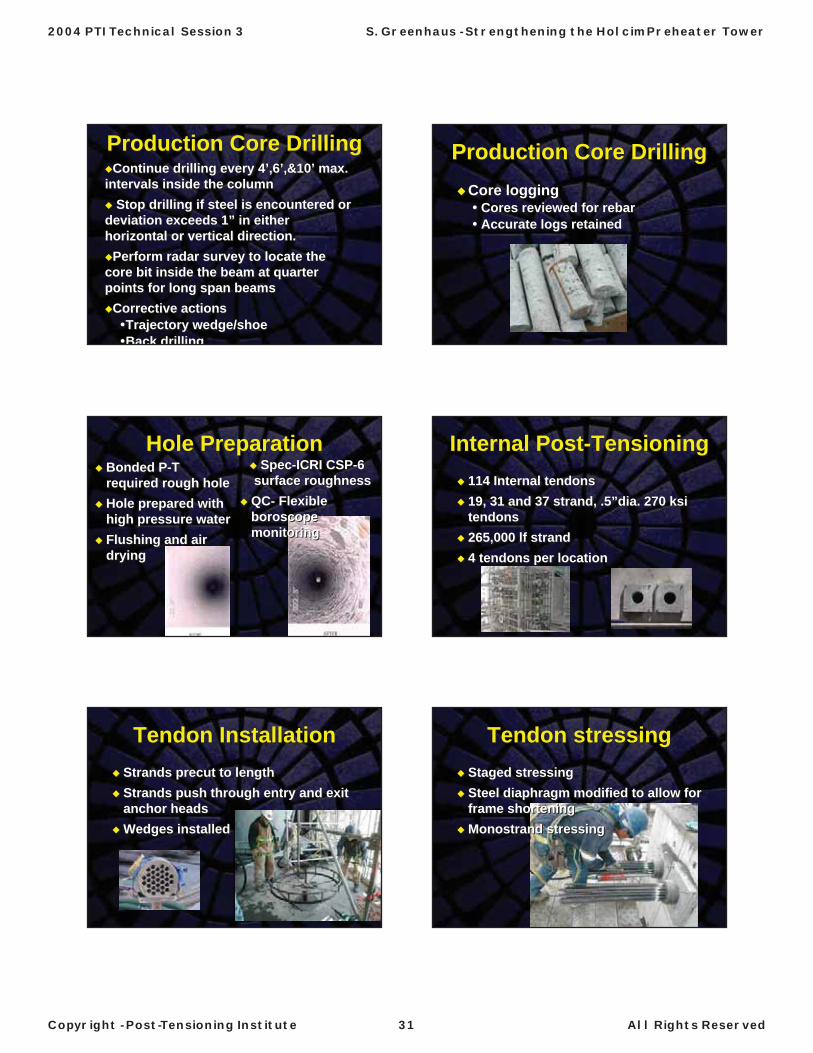
Production Core DrillingProduction Core DrillingContinue drilling every 4’,6’,&10’ max.
intervals inside the columnStop drilling if steel is encountered or
deviation exceeds 1” in either horizontal or vertical direction.
Perform radar survey to locate the core bit inside the beam at quarter points for long span beams
Corrective actionsTrajectory wedge/shoeBack drilling
Continue drilling every 4’,6’,&10’ max. intervals inside the column
Stop drilling if steel is encountered or deviation exceeds 1” in either horizontal or vertical direction.
Perform radar survey to locate the core bit inside the beam at quarter points for long span beams
Corrective actionsTrajectory wedge/shoeBack drilling
Production Core DrillingProduction Core DrillingCore logging
Cores reviewed for rebarAccurate logs retained
Core loggingCores reviewed for rebarAccurate logs retained
Hole PreparationHole PreparationBonded P-T required rough holeHole prepared with high pressure waterFlushing and air drying
Bonded P-T required rough holeHole prepared with high pressure waterFlushing and air drying
Spec-ICRI CSP-6 surface roughnessQC- Flexibleboroscopemonitoring
Spec-ICRI CSP-6 surface roughnessQC- Flexibleboroscopemonitoring
Internal Post-TensioningInternal Post-Tensioning114 Internal tendons19, 31 and 37 strand, .5”dia. 270 ksi tendons265,000 lf strand4 tendons per location
114 Internal tendons19, 31 and 37 strand, .5”dia. 270 ksi tendons265,000 lf strand4 tendons per location
Tendon InstallationTendon InstallationStrands precut to lengthStrands push through entry and exit anchor headsWedges installed
Strands precut to lengthStrands push through entry and exit anchor headsWedges installed
Tendon stressingTendon stressingStaged stressingSteel diaphragm modified to allow for frame shorteningMonostrand stressing
Staged stressingSteel diaphragm modified to allow for frame shorteningMonostrand stressing
2004 PTI Technical Session 3 S. Greenhaus - Strengthening the Holcim Preheater Tower
Copyright - Post-Tensioning Institute 31 All Rights Reserved
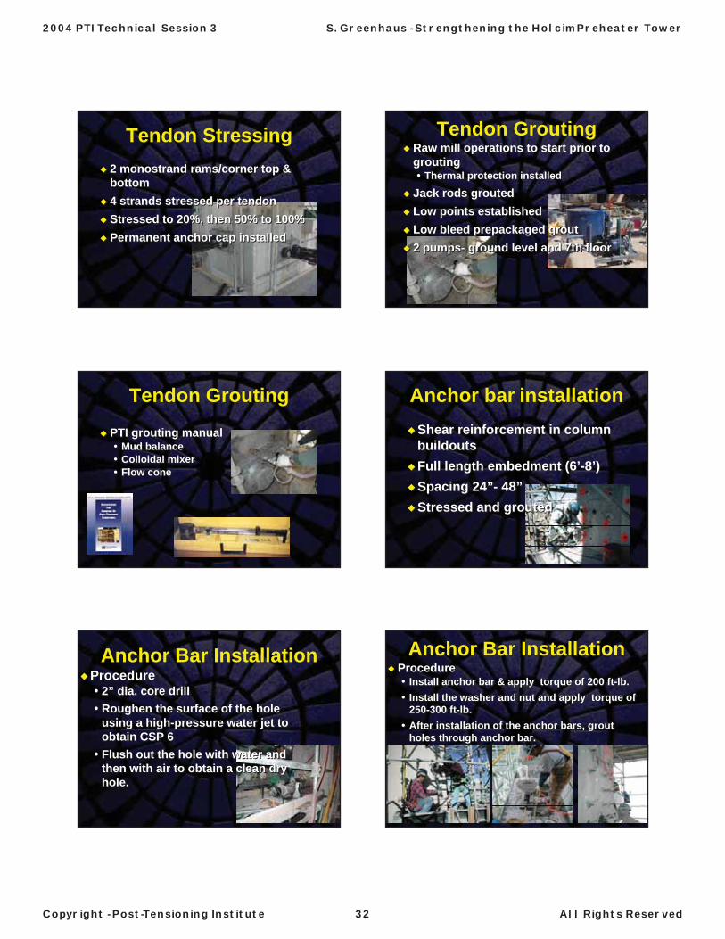
Tendon StressingTendon Stressing2 monostrand rams/corner top & bottom4 strands stressed per tendonStressed to 20%, then 50% to 100%Permanent anchor cap installed
2 monostrand rams/corner top & bottom4 strands stressed per tendonStressed to 20%, then 50% to 100%Permanent anchor cap installed
Tendon GroutingTendon GroutingRaw mill operations to start prior to grouting
Thermal protection installed
Jack rods groutedLow points establishedLow bleed prepackaged grout2 pumps- ground level and 7th floor
Raw mill operations to start prior to grouting
Thermal protection installed
Jack rods groutedLow points establishedLow bleed prepackaged grout2 pumps- ground level and 7th floor
Tendon GroutingTendon Grouting
PTI grouting manualMud balanceColloidal mixerFlow cone
PTI grouting manualMud balanceColloidal mixerFlow cone
Anchor bar installationAnchor bar installationShear reinforcement in column buildoutsFull length embedment (6’-8’)Spacing 24”- 48”Stressed and grouted
Shear reinforcement in column buildoutsFull length embedment (6’-8’)Spacing 24”- 48”Stressed and grouted
Anchor Bar InstallationAnchor Bar InstallationProcedure
2” dia. core drill Roughen the surface of the hole using a high-pressure water jet to obtain CSP 6Flush out the hole with water and then with air to obtain a clean dry hole.
Procedure2” dia. core drill Roughen the surface of the hole using a high-pressure water jet to obtain CSP 6Flush out the hole with water and then with air to obtain a clean dry hole.
Anchor Bar InstallationAnchor Bar InstallationProcedure
Install anchor bar & apply torque of 200 ft-lb.Install the washer and nut and apply torque of 250-300 ft-lb.After installation of the anchor bars, groutholes through anchor bar.
ProcedureInstall anchor bar & apply torque of 200 ft-lb.Install the washer and nut and apply torque of 250-300 ft-lb.After installation of the anchor bars, groutholes through anchor bar.
2004 PTI Technical Session 3 S. Greenhaus - Strengthening the Holcim Preheater Tower
Copyright - Post-Tensioning Institute 32 All Rights Reserved
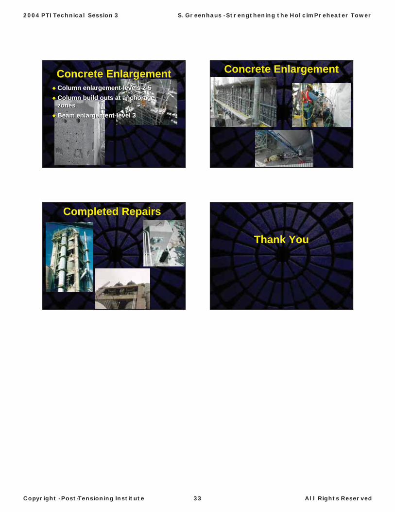
Concrete EnlargementConcrete EnlargementColumn enlargement-levels 2-5Column build outs at anchorage zonesBeam enlargement-level 3
Column enlargement-levels 2-5Column build outs at anchorage zonesBeam enlargement-level 3
Concrete EnlargementConcrete Enlargement
Completed RepairsCompleted Repairs
Thank YouThank You
2004 PTI Technical Session 3 S. Greenhaus - Strengthening the Holcim Preheater Tower
Copyright - Post-Tensioning Institute 33 All Rights Reserved