Embed Size (px)
Citation preview

Strength Determination of "Tooth-Paste" Like Sand and Gravel Washing Fines Using DMT
David L. Knott, P.E. and James M. Sheahan, P.E. HDR Engineering, Inc. 3 Gateway Center Pittsburgh, PA 15222-1074 Phone: (412) 497-6000; E-mail: [email protected] [email protected]
Susan L. Young, CPG HDR Engineering, Inc. 4480 Cox Road, Suite 103 Glen Allen, VA 23060-6751 Phone: (804) 648-6630; E-mail: [email protected] Keywords: dilatometer, undrained shear strength, drained shear strength, confined dike facility (CDF), borehole shear test, settlement, short-term stability, long-term stability, sand and gravel washings
ABSTRACT: An approximately 18 acre (0.l km2) site was proposed for a Confined Dike Facility (CDF) for the disposal of dredged materials. Based on available information the site was believed to be located on natural ground. During the initial investigation, the site was found to be located on top of a slurry pond that had been covered with fill. The slurry pond was previously used for the disposal of slurried fines “washings” from sand and gravel processing. The washings had the consistency of “toothpaste”, even after having been covered with fill for at least 14 years. The initial investigation used Standard Penetration Tests (SPTs) and Shelby tubes to obtain samples, since the materials at the site were expected to be a natural deposit. Two types of washings were encountered – “clayey washings,” which were primarily clay; and “sandy washings,” generally consisting of sand with various amounts of clay, gravel and silt. The clayey washings were an almost pure clay and had pocket penetrometer values of 0 tsf (0 kPa) even with the special foot attachment for very soft soils. Laboratory strength tests were not able to be performed on the Shelby tubes samples, since the sample of the washings deformed upon opening the tube due to lack of confinement. To obtain strength parameters for design, in situ techniques were assessed for a supplemental investigation. DMT testing was selected to determine the undrained shear strength of the washings, which varied from 83.5 to 355 psf (4 to 17 kPa) over a depth of 31.5 feet (9.6 m) in an area without surface fill and was higher in areas where fill had been placed. Borehole shear testing of the washings was selected to provide drained strength parameters, which varied from 15.9º and 1.1 psf (0.1 kPa) to 27º and 9 psf (0.4 kPa). The investigation indicated that washings up to 36.5 feet (11.1 m) thick were present beneath the entire site to depths varying from 21 to 36.5 feet (6.4 to 11.1 m). The data was then used to design the CDF.
1 BACKGROUND
The work described in this paper was performed as part of a project to dredge Lake Accotink, a county-owned lake in Fairfax County, Virginia, in a highly developed suburban area. The materials dredged from the lake are to be pumped through a slurry line to a disposal facility for sedimentation. The proposed disposal facility consists of a Confined Dike Facility (CDF) with a height of 12 feet (3.7 m) and a capacity of 53.3 acre-feet (65,745 m3). The CDF capacity was subsequently reduced to 33.5 acre-feet (41,322 m3). The site and current CDF configuration are shown on Figure 1. Confined Dike Disposal Facility
PROCEEDINGS FROM THE SECOND INTERNATIONAL FLAT DILATOMETER CONFERENCE
365

Figure 1. This approach results in significant savings for the client in lieu of hauling the dredged material from the lake which required high dewatering and trucking costs.
The site location was initially determined to be suitable and was to have been “natural ground.” However, during the initial investigation, the site was found to have been a slurry pond for “washings” from a sand and gravel processing operation that had been subsequently covered with fill. No other suitable sites were available, so work progressed even after the presence of the poor soil conditions was determined.
The history of the site was determined using
aerial photography, since no other information was available. The photos indicated that the site was surface mined for sand and gravel, probably prior to 1940, and the slurry pond is visible on a 1953 photo. Aerial photography indicated that the pond configuration changed over time with the expansion of the dike system, including the use of “splitter dikes” (dikes to divide the facility into cells) as shown on Figure 2A. The historical photos show that the area within the slurry pond was filled with washings and then covered with fill. The fill consists of soil and materials from concrete truck washout. The site appears to have been in its current configuration since 1988 (Figure 2B). An active concrete plant is located adjacent to the site, and a portion of the site is used for the storage of precast concrete products. The current site elevation ranges from 250 to 260 feet (76.2 to 79.2 m) mean sea level (msl).
The sand and gravel mined at the site belonged to the Pliocene epoch, which consisted of varying amounts of sand and gravel, and lesser amounts of clay and silt. This material is underlain by the
Potomac Formation of the Cretaceous Age, which generally consisted of clay with sand and silt.
2 INITIAL SUBSURFACE INVESTIGATION
Ten borings, in which Standard Penetration Tests (SPTs) were performed, were drilled as shown in Figure 1. The borings were advanced using hollow stem augers. In addition, four test pits (TPs) were excavated with a large track backhoe. A typical subsurface section with the proposed CDF dike is shown on Figure 3. Generally, the site could be subdivided into two areas, the field area and the pond area, as shown on Figure 1. The conditions in each are described below.
Figure 2A. Slurry Pond at CDF Site in 1962
Figure 2B. Slurry Pond at CDF Site in 1988
Figure 3. Typical CDF Section at Dilatometer Sounding B-12
PROCEEDINGS FROM THE SECOND INTERNATIONAL FLAT DILATOMETER CONFERENCE
366

2.1 Field Area The field area consisted of a relatively level area that had been created by filling over the washings in the slurry pond. Part of the area had been used as a baseball field. The borings in the field area, B-7, B-8, B-9, and B-10, generally encountered fill, varying in thickness from 11.5 to 21.5 feet (3.5 to 6.6 m), overlying very soft clay (clayey washings) or loose sand (sandy washings). The fill was also encountered in Test Pits (TPs) 1, 2, and 3. It varied from clayey silty sand to “concrete truck washout” that was so hard it could not be excavated with a medium-sized trackhoe. Washings up to 34 feet (10.4 m) thick were encountered beneath the fill in borings that penetrated their full thickness.
A groundwater observation well was installed in one of the borings, and the depth to groundwater was found to vary from 3.5 feet (1.1 m) (winter) to 9 feet (2.7 m) (summer) below the surface. The shallow depth to groundwater is probably due to the precipitation being confined to this area as a result of the slurry pond dikes. 2.2 Pond Area
The pond area consists of two low-lying areas in which surface water is present to varying depths during the year—Ponds 1 and 2 (see Figure 1). The ground surfaces of the ponds are the remains of the top of the original slurry pond surface, and the sides are the interior of the slurry pond dike and the edge of fill (Figure 4). The washings
could be walked on where a crust was established or where vegetation had developed.
Desiccation cracks extended to depths of several feet in the Pond 2 area. Borings B-2, B-4, and B-6 were drilled around the perimeter of
Ponds 1 and 2 where access was possible to obtain samples of the washings (Figure 5). Shelby tubes were taken in the washings in several borings.
Generally, the borings encountered several feet of fill underlain by very soft clay (washings). Borings B-2 and B-4 encountered natural ground at depths of 36.5 feet (11.1 m) (elevation 201.5 feet msl (61.4 m)) and 35 feet (10.7 m) (elevation 208 feet msl (63.4 m)), respectively. The natural ground consisted of dense to very dense bluish/greenish gray fine sandy silt. Boring B-6 encountered very soft clay (washings) to 25 feet (7.6 m) (elevation 213 feet msl (64.9 m)); at which point the interior side of the slurry pond dike was encountered. The slurry pond dike material consisted of hard silty clay. Natural material, similar to that from the other borings, was encountered beneath the slurry pond dike at a depth of 30 feet (9.1 m) (elevation 208 feet msl) (63.4 m).
Figure 5. Approximate boring locations in Pond 1 area. View from slurry pond dike.
Figure 4. Desiccation cracks in Pond 1 area looking toward slurry pond dike.
Figure 6. Hard, desiccated and soft, wet clayey washings at Test Pit 4
PROCEEDINGS FROM THE SECOND INTERNATIONAL FLAT DILATOMETER CONFERENCE
367

Test pit TP–4 was excavated at the edge of Pond 2. It encountered clay washings, which were hard and blocky due to desiccation in the upper 2 feet (0.6 m) and became softer with depth to 5 feet (1.5 m), where it became very soft (Figure 6). The moisture content increased with depth and was wet at 5 feet (1.5 m).
2.2.1 Southern and Western Dike Borings B-1, B-3, and B-5 were drilled in the slurry pond dike, since it was originally anticipated that this area would be used as part of the CDF. Soft soils were encountered beneath the slurry pond dike. Aerial photographs also showed the slurry pond dike being constructed over the washings. The presence of the underlying washings beneath the dike was confirmed by subsequent DMT testing. The location of the CDF was modified to exclude this area due to the presence of these soft soils. 2.3 Lab Testing
Representative samples of the various on-site soils were tested to provide classification data. However, classification test data will only be provided for the washings as summarized in Table 1.
Strength testing was attempted on undisturbed samples of clayey washings obtained in the initial investigation, but the sample started to expand and crack as it was being taken out of the tube as it was opened and was, therefore, not suitable for testing (Figure 7). Consolidation tests were performed on two undisturbed samples of the washings obtained in the initial investigation. The testing indicated that the Compression Index (cc), was 1.1; the Coefficient of Consolidation (cv) varied from 0.0213 to 0.0568 in2/min (13.7 to 36.6 mm2/min), the Initial Void ratio, e0, was 3.1077, the wet unit weight was 93.5 pcf (1500 kg/m3), and the preconsolidation pressure was 575 psf (27.5 KPa at
a depth of 11 feet (3.4 m), indicating normal consolidation. (Note: a DMT reading in B-14 at 11.2 feet (3.4 m) indicated a preconsolidation pressure of 501.3 psf and an OCR of 1.2.)
Gradation and hydrometer tests on the clayey washings indicate that 100 percent of the material passed the No. 200 sieve, and they consisted of 81.9 to 93.4 percent clay-sized material. The moisture content of the clayey washings generally decreased with depth from 84.2 to 43.3 percent from a depth of 6 to 31.5 feet (1.8 to 9.6 m) for borings in the pond area where the washings had been covered by several feet of fill. The composition of the sandy washings varied significantly, as indicated in Table 1. This may be the result of the proximity of the sampled location to the slurry discharge location.
The data from classification tests on the fill material from the field area indicated that it was generally sandy with varying amounts of clay, silt, and gravel.
Figure 7. Sample of clayey washings expanding due to lack of confinement during extrusion from Shelby Tube.
PROCEEDINGS FROM THE SECOND INTERNATIONAL FLAT DILATOMETER CONFERENCE
368

3 SUPPLEMENTAL INVESTIGATIONS
A supplemental investigation was performed to obtain further data on the site due to the variable conditions encountered and to obtain strength data for the washings. Dilatometer soundings (DMT) and borehole shear testing were performed by In-Situ Testing, L.C.
The dilatometer data was reduced using the WinDMT program from GPE, Inc. (GPE). The reduced data includes soil type, total unit weight, pore water pressure, preconsolidation pressure, strength, and over-consolidation ratio.
Since the DMT test is performed in about two-minute intervals at a given depth, excess pore water pressures cannot dissipate in fine-grained soils, and the undrained shear strength, Su, is determined. In sandy soils, it is assumed that drainage can occur and a drained plane strain friction angle (ø') is calculated. Dilatometer soundings were performed in five additional borings (B-11 through B-14 and B-17) to provide undrained shear strength values for the washings encountered in the pond area (B-12 and B-14), eastern field area (B-11), and western dike (B-13 and B-17). A track-mounted rig was used due to soft site conditions (Figure 8). Standard Penetration tests were performed in the harder fill materials
above the washings to advance the hole, since the dilatometer would be damaged by those materials. Starting near the base of the fill, dilatometer soundings were performed at about every 8 inches (20.3 cm) of depth in the washings until harder natural ground or gravel was encountered. The dilatometer soundings confirmed that the washings were generally clayey and contained thin sandy or
silty zones. Figure 9 shows all of the dilatometer data for the washings and natural soils in borings
B-11, B-12, B-13, and B-14, while Figure 10 only provides data on the washings, since their strength is much lower than that of the natural soils. Figure 10 indicates that higher strengths are present in washings that have been covered by fill or underlie the dike (B-11, B-12, and B-13) than the washings with minimal overlying fill (B-14). The figure also indicates that there is generally some strength gain with depth, which is likely due to normal consolidation. DMT results for Boring B-14, in particular, exhibit this trend.
Borehole shear tests were performed in borings to obtain drained shear strength design parameters for the washings. The borehole shear device was manufactured by Handy Geotechnical Instruments, Inc. (Handy 2002) Those borings were advanced using hollow stem augers to just above the test
Figure 9. In-place undrained shear strength of all soils by DMT. (Note: Gaps in data indicate granular material)
Figure 10. In-place undrained shear strength of washings by DMT. (Note: Gaps in data indicate granular material)
Figure 8. Track-mounted DMT rig.
PROCEEDINGS FROM THE SECOND INTERNATIONAL FLAT DILATOMETER CONFERENCE
369
sampling interval, at which point a cutting head and drilling mud were used to advance the borings.
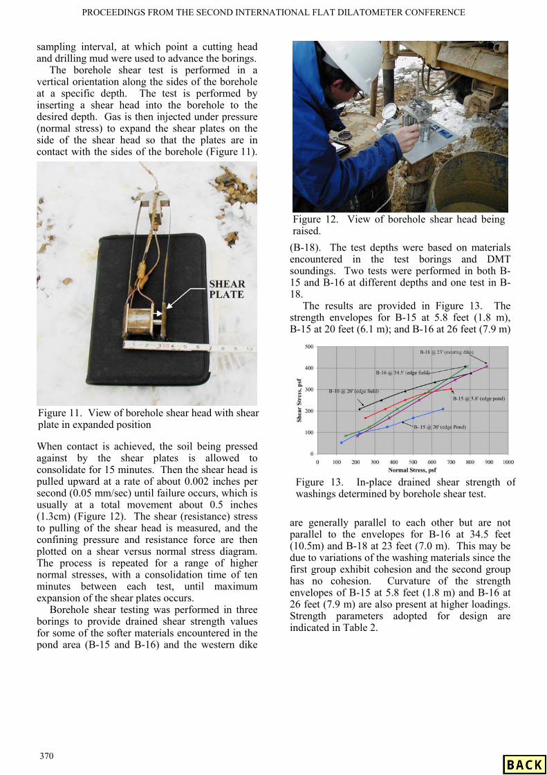
The borehole shear test is performed in a vertical orientation along the sides of the borehole at a specific depth. The test is performed by inserting a shear head into the borehole to the desired depth. Gas is then injected under pressure (normal stress) to expand the shear plates on the side of the shear head so that the plates are in contact with the sides of the borehole (Figure 11).
When contact is achieved, the soil being pressed against by the shear plates is allowed to consolidate for 15 minutes. Then the shear head is pulled upward at a rate of about 0.002 inches per second (0.05 mm/sec) until failure occurs, which is usually at a total movement about 0.5 inches (1.3cm) (Figure 12). The shear (resistance) stress to pulling of the shear head is measured, and the confining pressure and resistance force are then plotted on a shear versus normal stress diagram. The process is repeated for a range of higher normal stresses, with a consolidation time of ten minutes between each test, until maximum expansion of the shear plates occurs.
Borehole shear testing was performed in three borings to provide drained shear strength values for some of the softer materials encountered in the pond area (B-15 and B-16) and the western dike
(B-18). The test depths were based on materials encountered in the test borings and DMT soundings. Two tests were performed in both B-15 and B-16 at different depths and one test in B-18.
The results are provided in Figure 13. The strength envelopes for B-15 at 5.8 feet (1.8 m), B-15 at 20 feet (6.1 m); and B-16 at 26 feet (7.9 m)
are generally parallel to each other but are not parallel to the envelopes for B-16 at 34.5 feet (10.5m) and B-18 at 23 feet (7.0 m). This may be due to variations of the washing materials since the first group exhibit cohesion and the second group has no cohesion. Curvature of the strength envelopes of B-15 at 5.8 feet (1.8 m) and B-16 at 26 feet (7.9 m) are also present at higher loadings. Strength parameters adopted for design are indicated in Table 2.
Figure 11. View of borehole shear head with shear plate in expanded position
Figure 13. In-place drained shear strength of washings determined by borehole shear test.
Figure 12. View of borehole shear head being raised.
PROCEEDINGS FROM THE SECOND INTERNATIONAL FLAT DILATOMETER CONFERENCE
370

4. ANALYSIS
4.1 Slope Stability The stability of the CDF was assessed at several locations using the STABL6H computer program. Analyses were performed for the new CDF dike at the boundary between the field and pond areas, the southeastern side of the CDF, and the eastern side of the CDF. The locations for the analyses were selected based on being representative and/or being a more critical location. Both drained and undrained analyses were performed and seepage through the CDF dike was considered as appropriate based on whether or not dredged material would be impounded for the condition being analyzed. The washings were divided into zones based on strength data from the testing and estimated at intermediate locations. The typical dike configuration was about 100 feet (30.5 m) wide at its base, has 3H:1V interior and exterior slopes, and top width of 14 feet (4.3 m). Minimum factor of safety requirements were in accordance with USCOE guidelines (USCOE 1987 and 2000).
Stability analyses for rapid filling and rapid drawdown were not made, since inflow and outflow to the CDF is controlled.
Due to the low strength of the materials underlying the CDF, the results of the analyses indicated that the dike needed to be constructed in stages to achieve the targeted minimum factor of safety and set back from the edge of the pond area. The first stage dike was made to be approximately half the size of the full dike. The analyses also indicated that a geogrid-reinforced buttress was needed in the pond area prior to construction of the full dike. Construction of the first stage dike would allow some strength gain in the materials underlying the dike due to consolidation. Staging
of dike construction also allowed for dredging operations to begin so that sand could be generated for use as a buttress in the pond area prior to constructing the Stage 2 dike. In a portion of the field area, the interior dike slopes had to be flattened to 6H:1V and the floor of the CDF raised due to the presence of washings at shallow depths. 4.2 Settlement
An assessment of the long-term settlement of the full CDF dike section at the edge of the field/pond area was performed using boring and laboratory data. The stratigraphy was based on Boring B-12, in which dilatometer soundings were taken at 8-inch (20.3 cm) intervals, resulting in a complete profile of the washings, as shown in Figure 3. The fill overlying the washings was considered relatively incompressible under the CDF dike load, based on its being a dense granular material. The underlying washings were about 26 feet (7.9 m) thick. As shown in Figure 3, the washings consisted of clayey washing separated by several layers of sandy washings. Relatively incompressible natural soils, consisting of clayey silt, were encountered below the washings. Long-term settlement was estimated for each of the clayey washings layers. Consolidation settlement was estimated to be about 15 inches (38.1 cm) at this location. However, the magnitude of settlement across the site could vary due to variations in the thickness and pre-loading of the washings and other factors such as dike staging and rate of construction. Immediate settlement due to compression of the sandy layers in the washings should occur during construction. In addition, some additional long-term settlement could occur due to the weight of the dredged materials.
The time for 90 percent of the new dike settlement to occur was also estimated to assess the impact of settlement on dike freeboard requirements. The time for 90 percent settlement to occur could vary from less than a year to several years, depending on the number and persistence of the sandy washings resulting in either single or double drainage of the clayey washings. Therefore, raising of the dike is to be performed as needed to provide adequate free-board while the facility is operating.
5 CONCLUSIONS
The DMT soundings allowed the strength of very soft clay, which could not otherwise be determined by SPT; pocket penetrometer, even with the
Table 2. Borehole Shear Test Drained Strength Values Selected for Design
PROCEEDINGS FROM THE SECOND INTERNATIONAL FLAT DILATOMETER CONFERENCE
371

special foot attachment; and laboratory testing, to be determined. The DMT data also provided a detailed subsurface profile of material types and strengths, which was not possible to obtain with SPT tests due to the softness of the material. The project also showed how DMT and conventional boring techniques can complement each other.
After evaluating the data from the investigations, it was determined that the site could be used for final disposal of dredged material. This allowed the use of a very poor site and saving the client a significant amount of money over hauling dredged material to another site.
REFERENCES
GPE, WinDMT, Version 1.1, “Marchetti Dilatometer Test Data Reduction Program.”
Handy Geotechnical Instruments, Inc., 2002, “Borehole Shear Test Instructions”, Madrid, Iowa.
U.S. Army Corps of Engineers, 1987, Engineering and Design – Confined Disposal of Dredged Material
U.S. Army Corps of Engineers, 2000, Design and Construction of Levees.
PROCEEDINGS FROM THE SECOND INTERNATIONAL FLAT DILATOMETER CONFERENCE
372


![New York Tribune.(New York, NY) 1915-08-20 [p 3]. · 2018. 12. 7. · Vivaudou's Peroxide Tooth Paste Large Tube, 25c Cleans Whitens Preserves Themostpleasingand effective tooth preparation](https://img.dokumen.tips/doc/110x75/5ff5940fc11ba020643d6e52/new-york-tribunenew-york-ny-1915-08-20-p-3-2018-12-7-vivaudous-peroxide.jpg)