Embed Size (px)
Citation preview

SG24-5474-00
International Technical Support Organization
www.redbooks.ibm.com
Storage Area Networks: Tape Future in Fabrics
Matthias Werner, Jonathan Jeans, Barbara Manger, Charles Silvan


Storage Area Networks: Tape Future in Fabrics
January 2000
SG24-5474-00
International Technical Support Organization

© Copyright International Business Machines Corporation 2000. All rights reserved.Note to U.S Government Users – Documentation related to restricted rights – Use, duplication or disclosure issubject to restrictions set forth in GSA ADP Schedule Contract with IBM Corp.
First Edition (January 2000)
This edition applies to a range of IBM products related to Storage Area Networks, including but notlimited to the IBM SAN Data Gateway, the IBM Fibre Channel Switch, the Magstar 3575 Tape Library,and the Tivoli Storage Manager (formerly ADSM).
Comments may be addressed to:IBM Corporation, International Technical Support OrganizationDept. QXXE Building 80-E2650 Harry RoadSan Jose, California 95120-6099
When you send information to IBM, you grant IBM a non-exclusive right to use or distribute theinformation in any way it believes appropriate without incurring any obligation to you.
Before using this information and the product it supports, be sure to read the general information inAppendix C, “Special notices” on page 135.
Take Note!

Contents
Figures . . . . . . . . . . . . . . . . . . . . . . . . . . . . . . . . . . . . . . . . . . . . . . . . . . . vii
Tables. . . . . . . . . . . . . . . . . . . . . . . . . . . . . . . . . . . . . . . . . . . . . . . . . . . . .ix
Preface . . . . . . . . . . . . . . . . . . . . . . . . . . . . . . . . . . . . . . . . . . . . . . . . . . . .xiThe team that wrote this redbook. . . . . . . . . . . . . . . . . . . . . . . . . . . . . . . . . . . .xiComments Welcome . . . . . . . . . . . . . . . . . . . . . . . . . . . . . . . . . . . . . . . . . . . . xiii
Chapter 1. SAN . . . . . . . . . . . . . . . . . . . . . . . . . . . . . . . . . . . . . . . . . . . . . 11.1 Definitions and terminology . . . . . . . . . . . . . . . . . . . . . . . . . . . . . . . . . 4
1.1.1 What is a SAN? . . . . . . . . . . . . . . . . . . . . . . . . . . . . . . . . . . . . . . 41.1.2 Fibre Channel. . . . . . . . . . . . . . . . . . . . . . . . . . . . . . . . . . . . . . . . 61.1.3 SAN topologies. . . . . . . . . . . . . . . . . . . . . . . . . . . . . . . . . . . . . . . 8
1.2 Why use a SAN for tape ? . . . . . . . . . . . . . . . . . . . . . . . . . . . . . . . . . . 81.2.1 Tape usage in Open Systems environments . . . . . . . . . . . . . . . . . 81.2.2 Tape solutions are ready for the environment today . . . . . . . . . . 111.2.3 Gigabit ethernet versus the SAN . . . . . . . . . . . . . . . . . . . . . . . . 121.2.4 SCSI disk solutions can look like a SAN solution . . . . . . . . . . . . 121.2.5 Tape solutions really need Fibre Channel . . . . . . . . . . . . . . . . . . 131.2.6 Tape is expensive — disk is cheap . . . . . . . . . . . . . . . . . . . . . . . 13
1.3 SAN issues . . . . . . . . . . . . . . . . . . . . . . . . . . . . . . . . . . . . . . . . . . . . 151.4 Marketplace . . . . . . . . . . . . . . . . . . . . . . . . . . . . . . . . . . . . . . . . . . . . 16
Chapter 2. SAN opportunities . . . . . . . . . . . . . . . . . . . . . . . . . . . . . . . . 192.1 Solutions available in the near term . . . . . . . . . . . . . . . . . . . . . . . . . . 20
2.1.1 Tape connectivity . . . . . . . . . . . . . . . . . . . . . . . . . . . . . . . . . . . . 202.1.2 Tape pooling or sharing . . . . . . . . . . . . . . . . . . . . . . . . . . . . . . . 212.1.3 Tape extension for disaster recovery . . . . . . . . . . . . . . . . . . . . . 232.1.4 Fully redundant, disaster tolerant tape solutions . . . . . . . . . . . . . 25
2.2 New opportunities . . . . . . . . . . . . . . . . . . . . . . . . . . . . . . . . . . . . . . . 262.2.1 LAN-free backup . . . . . . . . . . . . . . . . . . . . . . . . . . . . . . . . . . . . 262.2.2 Server-free backup . . . . . . . . . . . . . . . . . . . . . . . . . . . . . . . . . . . 282.2.3 A new paradigm for a backup server using a SAN . . . . . . . . . . . 312.2.4 Complex backup scenarios. . . . . . . . . . . . . . . . . . . . . . . . . . . . . 332.2.5 A new architecture for the backup server . . . . . . . . . . . . . . . . . . 352.2.6 Intelligent tape subsystems (ITS) and SAN — is this the future ? 36
Chapter 3. SAN solutions . . . . . . . . . . . . . . . . . . . . . . . . . . . . . . . . . . . 413.1 IBM SAN Initiative . . . . . . . . . . . . . . . . . . . . . . . . . . . . . . . . . . . . . . . 413.2 IBM SAN Hardware Base layer. . . . . . . . . . . . . . . . . . . . . . . . . . . . . . 43
3.2.1 IBM Magstar MP Product Line . . . . . . . . . . . . . . . . . . . . . . . . . . 44
© Copyright IBM Corp. 2000 iii

3.2.2 IBM Magstar 3590 Product Line . . . . . . . . . . . . . . . . . . . . . . . . . 453.2.3 Fibre Channel RAID Storage Server . . . . . . . . . . . . . . . . . . . . . . 463.2.4 Enterprise Storage Server . . . . . . . . . . . . . . . . . . . . . . . . . . . . . 473.2.5 LTO . . . . . . . . . . . . . . . . . . . . . . . . . . . . . . . . . . . . . . . . . . . . . . 48
3.3 IBM SAN Connectivity layer . . . . . . . . . . . . . . . . . . . . . . . . . . . . . . . . 503.3.1 IBM Fibre Channel Switch . . . . . . . . . . . . . . . . . . . . . . . . . . . . . 513.3.2 IBM SAN Data Gateway . . . . . . . . . . . . . . . . . . . . . . . . . . . . . . . 523.3.3 IBM SAN Data Gateway Router . . . . . . . . . . . . . . . . . . . . . . . . . 563.3.4 IBM Fibre Channel Storage Hub . . . . . . . . . . . . . . . . . . . . . . . . . 573.3.5 Fibre Channel Adapters . . . . . . . . . . . . . . . . . . . . . . . . . . . . . . . 58
3.4 IBM SAN Management layer . . . . . . . . . . . . . . . . . . . . . . . . . . . . . . . 593.4.1 IBM SAN Management Initiative software . . . . . . . . . . . . . . . . . . 603.4.2 IBM StorWatch SAN Data Gateway Specialist . . . . . . . . . . . . . . 623.4.3 Zoning or access control. . . . . . . . . . . . . . . . . . . . . . . . . . . . . . . 65
3.5 IBM SAN Exploitation layer . . . . . . . . . . . . . . . . . . . . . . . . . . . . . . . . 663.5.1 Tivoli Storage Manager. . . . . . . . . . . . . . . . . . . . . . . . . . . . . . . . 673.5.2 Tivoli Removable Media Manager. . . . . . . . . . . . . . . . . . . . . . . . 77
3.6 IBM SAN Services and Support layer . . . . . . . . . . . . . . . . . . . . . . . . . 783.6.1 Interoperability . . . . . . . . . . . . . . . . . . . . . . . . . . . . . . . . . . . . . . 783.6.2 SAN services . . . . . . . . . . . . . . . . . . . . . . . . . . . . . . . . . . . . . . . 80
Chapter 4. IBM SAN Data Gateway implementation . . . . . . . . . . . . . . . 814.1 Device mapping considerations . . . . . . . . . . . . . . . . . . . . . . . . . . . . . 81
4.1.1 Device mapping in FC environments . . . . . . . . . . . . . . . . . . . . . 814.1.2 Mapping devices to targets and LUNs . . . . . . . . . . . . . . . . . . . . 84
4.2 Windows NT . . . . . . . . . . . . . . . . . . . . . . . . . . . . . . . . . . . . . . . . . . . . 854.2.1 Setup . . . . . . . . . . . . . . . . . . . . . . . . . . . . . . . . . . . . . . . . . . . . . 854.2.2 Host considerations . . . . . . . . . . . . . . . . . . . . . . . . . . . . . . . . . . 91
4.3 AIX . . . . . . . . . . . . . . . . . . . . . . . . . . . . . . . . . . . . . . . . . . . . . . . . . . . 924.3.1 Setup . . . . . . . . . . . . . . . . . . . . . . . . . . . . . . . . . . . . . . . . . . . . . 924.3.2 Host considerations . . . . . . . . . . . . . . . . . . . . . . . . . . . . . . . . . . 97
4.4 StorWatch SAN Data Gateway Specialist . . . . . . . . . . . . . . . . . . . . . . 984.4.1 File menu group . . . . . . . . . . . . . . . . . . . . . . . . . . . . . . . . . . . . . 994.4.2 View menu group . . . . . . . . . . . . . . . . . . . . . . . . . . . . . . . . . . . 1004.4.3 Admin menu group . . . . . . . . . . . . . . . . . . . . . . . . . . . . . . . . . . 1004.4.4 Tools menu group. . . . . . . . . . . . . . . . . . . . . . . . . . . . . . . . . . . 1014.4.5 Controls menu group . . . . . . . . . . . . . . . . . . . . . . . . . . . . . . . . 102
4.5 The Service Port interface . . . . . . . . . . . . . . . . . . . . . . . . . . . . . . . . 104
Chapter 5. Scenarios and sample configurations . . . . . . . . . . . . . . . 1095.1 Distance solution . . . . . . . . . . . . . . . . . . . . . . . . . . . . . . . . . . . . . . . 1095.2 Connectivity solution . . . . . . . . . . . . . . . . . . . . . . . . . . . . . . . . . . . . 1105.3 High availability solution . . . . . . . . . . . . . . . . . . . . . . . . . . . . . . . . . . 112
iv Storage Area Networks: Tape Future in Fabrics

5.3.1 High availability for SAN components . . . . . . . . . . . . . . . . . . . . 1135.3.2 High availability for hosts in a SAN . . . . . . . . . . . . . . . . . . . . . . 114
5.4 Disaster recovery solution . . . . . . . . . . . . . . . . . . . . . . . . . . . . . . . . 1165.5 Tape sharing solutions . . . . . . . . . . . . . . . . . . . . . . . . . . . . . . . . . . . 117
5.5.1 Static tape sharing . . . . . . . . . . . . . . . . . . . . . . . . . . . . . . . . . . 1175.5.2 Homogeneous tape sharing . . . . . . . . . . . . . . . . . . . . . . . . . . . 1185.5.3 Heterogeneous tape sharing. . . . . . . . . . . . . . . . . . . . . . . . . . . 119
5.6 Disk and tape on SAN . . . . . . . . . . . . . . . . . . . . . . . . . . . . . . . . . . . 119
Appendix A. Fiber Channel discussion . . . . . . . . . . . . . . . . . . . . . . . . . 121A.1 Layers . . . . . . . . . . . . . . . . . . . . . . . . . . . . . . . . . . . . . . . . . . . . . . . . . . . 121
A.1.1 Lower layers . . . . . . . . . . . . . . . . . . . . . . . . . . . . . . . . . . . . . . . . . . 121A.1.2 Upper layers . . . . . . . . . . . . . . . . . . . . . . . . . . . . . . . . . . . . . . . . . . 122
A.2 Topologies . . . . . . . . . . . . . . . . . . . . . . . . . . . . . . . . . . . . . . . . . . . . . . . 122A.3 Classes of Service . . . . . . . . . . . . . . . . . . . . . . . . . . . . . . . . . . . . . . . . . 123A.4 SAN components . . . . . . . . . . . . . . . . . . . . . . . . . . . . . . . . . . . . . . . . . . 123
A.4.1 SAN servers . . . . . . . . . . . . . . . . . . . . . . . . . . . . . . . . . . . . . . . . . . 123A.4.2 SAN storage . . . . . . . . . . . . . . . . . . . . . . . . . . . . . . . . . . . . . . . . . . 124
A.5 SAN interconnects . . . . . . . . . . . . . . . . . . . . . . . . . . . . . . . . . . . . . . . . . 124A.5.1 Cables and connectors . . . . . . . . . . . . . . . . . . . . . . . . . . . . . . . . . . 124A.5.2 Gigabit Link Model (GLM). . . . . . . . . . . . . . . . . . . . . . . . . . . . . . . . 125A.5.3 Gigabit Interface Converters (GBIC). . . . . . . . . . . . . . . . . . . . . . . . 125A.5.4 Media Interface Adapters (MIA) . . . . . . . . . . . . . . . . . . . . . . . . . . . 125A.5.5 Adapters . . . . . . . . . . . . . . . . . . . . . . . . . . . . . . . . . . . . . . . . . . . . . 126A.5.6 Extenders . . . . . . . . . . . . . . . . . . . . . . . . . . . . . . . . . . . . . . . . . . . . 126A.5.7 Multiplexors. . . . . . . . . . . . . . . . . . . . . . . . . . . . . . . . . . . . . . . . . . . 126A.5.8 Hubs . . . . . . . . . . . . . . . . . . . . . . . . . . . . . . . . . . . . . . . . . . . . . . . . 126A.5.9 Routers . . . . . . . . . . . . . . . . . . . . . . . . . . . . . . . . . . . . . . . . . . . . . . 127A.5.10 Bridges . . . . . . . . . . . . . . . . . . . . . . . . . . . . . . . . . . . . . . . . . . . . . 127A.5.11 Gateways . . . . . . . . . . . . . . . . . . . . . . . . . . . . . . . . . . . . . . . . . . . 127A.5.12 Switches . . . . . . . . . . . . . . . . . . . . . . . . . . . . . . . . . . . . . . . . . . . . 128A.5.13 Directors . . . . . . . . . . . . . . . . . . . . . . . . . . . . . . . . . . . . . . . . . . . . 128
Appendix B. Terminology and other basics. . . . . . . . . . . . . . . . . . . . . . 131B.1 StorWatch . . . . . . . . . . . . . . . . . . . . . . . . . . . . . . . . . . . . . . . . . . . . . . . . 131B.2 SCSI . . . . . . . . . . . . . . . . . . . . . . . . . . . . . . . . . . . . . . . . . . . . . . . . . . . . 132B.3 Fibre Channel terms . . . . . . . . . . . . . . . . . . . . . . . . . . . . . . . . . . . . . . . . 133
Appendix C. Special notices . . . . . . . . . . . . . . . . . . . . . . . . . . . . . . . . . . 135
Appendix D. Related publications . . . . . . . . . . . . . . . . . . . . . . . . . . . . . . 139D.1 International Technical Support Organization publications. . . . . . . . . . . 139D.2 Redbooks on CD-ROMs . . . . . . . . . . . . . . . . . . . . . . . . . . . . . . . . . . . . . 139D.3 Other Publications . . . . . . . . . . . . . . . . . . . . . . . . . . . . . . . . . . . . . . . . . 140
v

How to get ITSO redbooks . . . . . . . . . . . . . . . . . . . . . . . . . . . . . . . . . . 141IBM Redbook Fax Order Form . . . . . . . . . . . . . . . . . . . . . . . . . . . . . . . . . . . . 142
Index . . . . . . . . . . . . . . . . . . . . . . . . . . . . . . . . . . . . . . . . . . . . . . . . . . . 143
IBM Redbooks evaluation . . . . . . . . . . . . . . . . . . . . . . . . . . . . . . . . . . . 147
vi Storage Area Networks: Tape Future in Fabrics

Figures
1. Almaden Research Center, San Jose . . . . . . . . . . . . . . . . . . . . . . . . . . . . . xi2. High speed data transfers . . . . . . . . . . . . . . . . . . . . . . . . . . . . . . . . . . . . . . 33. SAN components . . . . . . . . . . . . . . . . . . . . . . . . . . . . . . . . . . . . . . . . . . . . . 54. What is a SAN? . . . . . . . . . . . . . . . . . . . . . . . . . . . . . . . . . . . . . . . . . . . . . . 65. Fibre Channel protocol layers . . . . . . . . . . . . . . . . . . . . . . . . . . . . . . . . . . . 76. New network backup paradigm . . . . . . . . . . . . . . . . . . . . . . . . . . . . . . . . . . 97. Disk vs. tape storage costs over time . . . . . . . . . . . . . . . . . . . . . . . . . . . . 148. Cost of tape . . . . . . . . . . . . . . . . . . . . . . . . . . . . . . . . . . . . . . . . . . . . . . . . 159. Exponential growth of data . . . . . . . . . . . . . . . . . . . . . . . . . . . . . . . . . . . . 1710. Multi-host tape drive sharing . . . . . . . . . . . . . . . . . . . . . . . . . . . . . . . . . . . 2111. Tape pooling . . . . . . . . . . . . . . . . . . . . . . . . . . . . . . . . . . . . . . . . . . . . . . . 2312. Remote tape creation using a SAN . . . . . . . . . . . . . . . . . . . . . . . . . . . . . . 2413. Fully redundant tape subsystem configuration . . . . . . . . . . . . . . . . . . . . . 2514. LAN-free backup . . . . . . . . . . . . . . . . . . . . . . . . . . . . . . . . . . . . . . . . . . . . 2715. Server-free backup . . . . . . . . . . . . . . . . . . . . . . . . . . . . . . . . . . . . . . . . . . 3016. A new paradigm for the backup server using an internal SAN . . . . . . . . . 3217. Server-free backup with client’s disk on SAN and multicasting . . . . . . . . . 3318. Backup architecture of the future using a SAN . . . . . . . . . . . . . . . . . . . . . 3619. A SAN based virtualized tape subsystem for the future. . . . . . . . . . . . . . . 3920. IBM SAN Initiative . . . . . . . . . . . . . . . . . . . . . . . . . . . . . . . . . . . . . . . . . . . 4221. SAN Hardware Base layer of IBM SAN Initiative . . . . . . . . . . . . . . . . . . . . 4422. LTO tape formats . . . . . . . . . . . . . . . . . . . . . . . . . . . . . . . . . . . . . . . . . . . . 4923. SAN Connectivity layer of IBM SAN Initiative . . . . . . . . . . . . . . . . . . . . . . 5124. SAN Data Gateway zoning . . . . . . . . . . . . . . . . . . . . . . . . . . . . . . . . . . . . 5525. Using hubs for greater distances . . . . . . . . . . . . . . . . . . . . . . . . . . . . . . . . 5826. SAN Management layer of IBM SAN Initiative. . . . . . . . . . . . . . . . . . . . . . 5927. Total SAN management approach. . . . . . . . . . . . . . . . . . . . . . . . . . . . . . . 6228. SAN Data Gateway Specialist application model . . . . . . . . . . . . . . . . . . . 6329. SAN Exploitation layer of IBM SAN Initiative . . . . . . . . . . . . . . . . . . . . . . . 6730. Client-server transfer over Fibre Channel . . . . . . . . . . . . . . . . . . . . . . . . . 6831. 3590 SCSI connectivity . . . . . . . . . . . . . . . . . . . . . . . . . . . . . . . . . . . . . . . 7232. SAN 3590 connectivity. . . . . . . . . . . . . . . . . . . . . . . . . . . . . . . . . . . . . . . . 7333. Tivoli storage manager tape sharing . . . . . . . . . . . . . . . . . . . . . . . . . . . . . 7634. SAN Services and Support layer of IBM SAN Initiative . . . . . . . . . . . . . . . 7835. Basic SCSI connection to a system . . . . . . . . . . . . . . . . . . . . . . . . . . . . . . 8236. SAN Data Gateway attached through Fibre Channel — host view . . . . . . 8337. Device mapping views . . . . . . . . . . . . . . . . . . . . . . . . . . . . . . . . . . . . . . . . 8538. Installation setup . . . . . . . . . . . . . . . . . . . . . . . . . . . . . . . . . . . . . . . . . . . . 8639. SAN Data Gateway in the StorWatch SAN Data Gateway Specialist . . . . 8940. SAN Data Gateway Specialist — update firmware and restart . . . . . . . . . 90
© Copyright IBM Corp. 2000 vii

41. Restart warning message . . . . . . . . . . . . . . . . . . . . . . . . . . . . . . . . . . . . . 9042. Windows NT SCSI device settings . . . . . . . . . . . . . . . . . . . . . . . . . . . . . . 9143. StorWatch SAN Data Gateway — device view . . . . . . . . . . . . . . . . . . . . . 9244. AIX SAN lab configuration . . . . . . . . . . . . . . . . . . . . . . . . . . . . . . . . . . . . . 9445. AIX lab fcShowDevs output . . . . . . . . . . . . . . . . . . . . . . . . . . . . . . . . . . . . 9546. AIX lab as seen from ost28 . . . . . . . . . . . . . . . . . . . . . . . . . . . . . . . . . . . . 9647. SAN Data Gateway front panel . . . . . . . . . . . . . . . . . . . . . . . . . . . . . . . . 10048. Tools menu group . . . . . . . . . . . . . . . . . . . . . . . . . . . . . . . . . . . . . . . . . . 10149. Health check submenu . . . . . . . . . . . . . . . . . . . . . . . . . . . . . . . . . . . . . . 10150. Set access control function . . . . . . . . . . . . . . . . . . . . . . . . . . . . . . . . . . . 10351. Warning message after setting new access control. . . . . . . . . . . . . . . . . 10352. Distance solution with SAN Data Gateway . . . . . . . . . . . . . . . . . . . . . . . 11053. Magstar MP 3575 shared between two hosts . . . . . . . . . . . . . . . . . . . . . 11154. Magstar MP 3570 switched between two hosts. . . . . . . . . . . . . . . . . . . . 11255. Avoiding single point-of-failure SAN elements. . . . . . . . . . . . . . . . . . . . . 11356. SAN high availability using switches . . . . . . . . . . . . . . . . . . . . . . . . . . . . 11457. SAN configuration without single points-of-failure . . . . . . . . . . . . . . . . . . 11558. High availability using a Fibre Channel Switch . . . . . . . . . . . . . . . . . . . . 11659. SAN solution for disaster recovery. . . . . . . . . . . . . . . . . . . . . . . . . . . . . . 11760. Tape pooling solution. . . . . . . . . . . . . . . . . . . . . . . . . . . . . . . . . . . . . . . . 11861. Heterogenous tape sharing . . . . . . . . . . . . . . . . . . . . . . . . . . . . . . . . . . . 119
viii Storage Area Networks: Tape Future in Fabrics

Tables
1. FC adapter characteristics . . . . . . . . . . . . . . . . . . . . . . . . . . . . . . . . . . . . . 592. Library /drive partitioning versus sharing . . . . . . . . . . . . . . . . . . . . . . . . . . 663. Target ID and device mapping — native SCSI . . . . . . . . . . . . . . . . . . . . . 824. Device Map from the Host Point of View — with SAN Data Gateway . . . . 835. Tasks and associated commands . . . . . . . . . . . . . . . . . . . . . . . . . . . . . . 1086. Cable and connector distances . . . . . . . . . . . . . . . . . . . . . . . . . . . . . . . . 1257. Characteristics of different SCSI versions . . . . . . . . . . . . . . . . . . . . . . . . 132
© Copyright IBM Corp. 2000 ix

x Storage Area Networks: Tape Future in Fabrics

Preface
This redbook explains Storage Area Networks (SAN) and their possible andpractical implications and implementations on IBM storage products ingeneral, and tapes and tape libraries specifically. It applies to a range of IBMproducts related to Storage Area Networks, including but not limited to theIBM SAN Data Gateway, the IBM Fibre Channel Switch, the Magstar 3575Tape Library, and the Tivoli Storage Manager (formerly ADSM).
This redbook should be read together with a companion redbook, Introductionto Storage Area Networks, SAN, SG24-5470.
Written as a follow-on to the Introduction redbook, it moves on to the use ofSAN technology in tape environments. Tape drives and libraries tend to beexpensive devices. The ability to share them across many hosts creates ahuge financial advantage that can be one of the immediate benefits ofimplementing SAN in your enterprise! It includes a practical description of theproducts and components made available with the first IBM SAN productrollout, and contains IBM redbook-level details on how to make it work.
The team that wrote this redbook
This redbook was produced by a team of specialists from around the worldworking at the International Technical Support Organization San Jose Center:
Figure 1. Almaden Research Center, San Jose
© Copyright IBM Corp. 2000 xi

This project was designed and conducted by Matthias Werner. He isresponsible for tape and tape library projects at the International TechnicalSupport Organization, San Jose Center. His focus is to build and maintainhigh quality redbooks for use with IBM's leading tape library products in thefield. This is a pivotal function between the development labs and customers,Business Partners, and IBM professionals. Matthias also regularly teachestechnical workshops and sessions at conferences and seminars. Beforejoining the ITSO in July 1997, he was involved with most of the IBM tapelibrary projects in Switzerland, gaining broad experience in thetape-centric-computing environment since 1992. He can be reached [email protected].
Jonathan Jeans is a Senior Technical Consultant working for BerkshireComputer Products, an IBM Business Partner. Berkshire specializes instorage management, mostly for Open Systems in the Northeast area of theUnited States. He has over 30 years of experience in the storage field. Heholds a Masters degree in Applied Mathematics from Brown University. Hisareas of expertise include all areas of storage; tape, disk and storagemanagement software. He actively consults with clients in the Northeast,helping Berkshire’s clients select the proper storage solutions. Jonathan canbe reached at [email protected].
Barbara Manger-Strassguetl works for the Advanced Technical Sales Supportteam for SSD Sales Support EMEA. She has 6 years of experience in the tapearena. Her specialty is Open Systems attached tapes and libraries. For her, SANbreathes life into storage products, thus opening up new and interestingchallenges.
Charles Silvan is a Storage Specialist in IBM Global Services in Geneva(Switzerland). Charles holds a degree in physics from the ETHZ and a MastersDegree from Union College, Schenectady, NY. Charles has been with IBM for 29years, including 3 years at the World Trade Systems Center in Poughkeepsie. Hehas worked in a variety of areas, including MVS, TPNS, SNA, VM and DocumentProcessing. He is presently working in Services, where he is responsible forstorage and ADSM projects in the French-speaking part of Switzerland.
Thanks to the following people for their invaluable contributions to thisproject:
Kjell NystromInternational Technical Support Organization, San Jose Center
xii Storage Area Networks: Tape Future in Fabrics

Lee JesionowskiMark DoumasDonald DenningReed HancockKaren OrlandoGreg TevisErik BengdsMichael KaczmarskiJohn Kulakowski
IBM Tucson
Scott DrummondLisa Haut-Mikkelsen
IBM San Jose
Comments Welcome
Your comments are important to us!
We want our redbooks to be as helpful as possible. Please send us yourcomments about this or other redbooks in one of the following ways:
• Fax the evaluation form found in “IBM Redbooks evaluation” on page 147to the fax number shown on the form.
• Use the online evaluation form found at http://www.redbooks.ibm.com/
• Send your comments in an internet note to [email protected]
xiii

xiv Storage Area Networks: Tape Future in Fabrics

Chapter 1. SAN
During the past ten years, a major shift has occurred away from the legacymainframe host-centric storage model, to the distributed storage that iscurrently in vogue in the client/server model. Storage, for the most part,remains connected to the processor it services via a dedicated channel, suchas a SCSI bus. However, the large number of servers creates a complexenvironment and is difficult to manage. The high dedicated SCSI channelstend to be inflexible, especially in terms of distance between the storage andthe processor. At the same time, in the client/server model, the servers areinterconnected via network protocols, such as TCP/IP, so that these serverscan communicate with each other. These networks, LANs and WANS, tend tobe slow but very flexible. Interconnectivity is easy, but large blocks of datatraverse the network rather slowly and network disturbances are frequent.
The industry realizes that a new type of data network is needed to meet theneeds for the new distributed environments. The outcome of this process is aset of standards defining Fibre Channel. Fibre Channel brings the best ofboth worlds together — high speed and robustness of the storage channelwith the flexibility and few distance limitations of a standard network. FibreChannel is based on a network definition of five layers, where the lowestthree physical level layers define the pathway and the upper two layersenable the software protocol to move the actual data. See Figure 5 on page 7for a picture of these layers. (See Appendix A for a complete explanation.)
The uniqueness of Fibre Channel is that these two upper layers can be usedto carry older protocols. Protocols such as SCSI, ESCON, and IP can bemapped to the Fibre Channel transport service level. Therefore, reinvention ofTCP/IP, SCSI, ESCON, and other protocols is not necessary. The SCSIprotocol, and thus SCSI commands, can be transported across the FibreChannel infrastructure. A newer SCSI-3 protocol has been developed to allowfor some of the special functions available with the Fibre Channel standard.The Fibre Channel transport can use either copper or fiber optic cables, canmove 100 MB/sec across 10 km, and allows for an almost unlimited numberof devices to be interconnected.
Today many vendors are rushing to the market with new Fibre Channelproducts and putting them together into networks they call Storage AreaNetworks (SANs). The promise to resolve many of the industry’s major issues(speed, connectivity, availability, reliability, and manageability) is creatingquite an energetic market place. Using a SAN can potentially offer thefollowing benefits:
© Copyright IBM Corp. 2000 1
• Improvements in application availability: Storage that is independent ofapplication and accessible through alternate data paths.
• Higher application performance: Delegate storage processing to storagesubsystem off-loading server.
• Centralized and consolidated storage: Simpler management, scalability,flexibility, availability.
• Data transfer and vaulting to remote sites: Enables remote copy of data fordisaster protection.
• Simplified centralized management: Single image of storage mediasimplifies management.
IBM has launched a SAN Initiative, thereby leaping onto the band wagon.Today several products are available from IBM to begin the process ofcreating and exploiting this new technology. However, like all other vendors inthis area, IBM has found that the new technology is not so easy to implementand get to work seamlessly. No single vendor today markets all the pieces toput together a complete SAN, and it is unlikely that one ever will. Additionally,no single standard exists at this time, but rather there are a set of loosestandards that are being tightened as time passes. Thus, today, the majorissue facing SAN technology is the interoperability between the pieces of theSAN.
SANs create new methods of attaching storage to processors. (See Figure 2.)These new methods promise great improvements in both availability andperformance. Currently they are most commonly used to connect sharedstorage arrays to multiple processors, and are used by clustered servers forfailover. They can create the opportunity for various servers to share tapedrives and tape libraries. A SAN can be used to bypass traditional networkbottlenecks. It supports direct, high speed data transfers between serversand storage devices in the following three ways:
• Server to storage: This is the traditional model of interaction with storagedevices. The advantage is that the same storage device may be accessedserially or concurrently by multiple servers.
• Server to server: A SAN may be used for high-speed, high-volumecommunications between servers.
• Storage to storage: An example is a disk device backing up its data to atape without processor intervention. It could also be remote devicemirroring across the SAN.
2 Storage Area Networks: Tape Future in Fabrics

Figure 2. High speed data transfers
We expect that vendors will announce many solutions over the next fewyears. Many solutions will be effective, and many will lead us down the wrongpath. What we would hope is that this book can help you determine yourfuture vision, so you can decide which products you should pursue. IBM hasdeveloped many solutions to date, and will continue to deliver solutions at afast pace over the next few months and years. The goal is to deliver productsthat solve specific problems, that are economically justified, and that worktogether with other solutions developed. IBM intends to lead the SAN practicethrough service expertise which both:
• Allows us to implement specific IBM solutions at a customer site
• Helps customers put together heterogeneous solutions from variousvendors and ensures that they work together.
We hope that through this book, the reader will be able to recognize the valueof the SAN technology as it relates to tape, and will be able to understandseveral products available from IBM, to allow exploitation of the SANtechnology in the tape environment.
SAN Technology
HostServer
DiskSystem
HostServer
Tape Library
Storage toStorage -SCSI over FC
Server toServer -TCP/IPServer to
Storage -SCSI over FC
SAN 3

1.1 Definitions and terminology
This section will offer a general discussion of Fibre Channel (FC) architectureand SAN topologies, and should provide an adequate introduction to theterms that we use throughout this redbook. However, to get a betterunderstanding of FC and SAN technology, the reader may also refer to theredbook: Introduction to Storage Area Network, SAN, SG24-5470.
1.1.1 What is a SAN?There are many definitions for a SAN. Most are developed by the variousvendors to help market their own products. In this redbook, we will use thefollowing definition, which is quite broad in scope, but requires that someFibre Channel protocols are installed. Fibre Channel unlocks many limitationsplaced on the storage environment by the older channel architectures.
A SAN needs to have the following four elements:
1. Some elements of the network, such as Fibre Channel cables, a switch,a hub, or a gateway.
2. At least one host node. (Note that the node resides in the Host BusAdapter card and not in the host itself.)
3. At least one storage node. (Note that the node resides in the DeviceAdapter card and not in the storage subsystem itself.)
4. Some management software to manage such things as the devices,allocation, use, and configuration. The main purpose of the software isto enable the storage and host elements connected to the SAN tooperate with data integrity.
And here’s the IBM definition of a SAN:
A Storage Area Network (SAN) is a dedicated, centrally managed, secureinformation infrastructure, which enables any-to-any interconnection ofservers and storage systems.
Figure 3 shows the main components of a SAN. Thereafter, throughout thisdocument, we will only show a cloud with the words to depict a SAN. Thereader should keep in mind that this cloud is a simplification, and that mostSANs will have many elements such as switches, hubs, and gateways.However, it is simpler for us to ignore them in the figures.
4 Storage Area Networks: Tape Future in Fabrics

Figure 3. SAN components
These elements, when put together, create a Fibre Channel topology whichwe will call the SAN. The SAN is nearly limitless in architecture, but mostcurrent implementations are very limited in terms of distance and number ofconnections. The maximum switch size today is 32 ports, while the largesthubs have only 16 ports. (These elements, hubs and switches, and others aredefined in Appendix A.) Software management tools are also limited, andtend to be able to manage only a small subset of the SAN. Although theseSANs seem immature, they can solve some real-life problems. However, themajor reason most of the SANs are installed today is to obtain knowledge andexpertise in the technology so that, as it evolves, the enterprise can adopt thenew technology quickly and painlessly.
Figure 4 depicts a SAN with several processor types and several storagetypes. For the remainder of this book we will depict the SAN as a cloud, butthe reader should assume that each cloud can be made up of switches, hubs,gateways and bridges, as depicted in Figure 3. Notice that in this depictionthe processors are still able to communicate across the LAN. With this level ofconnectivity comes a burden — and that is, how to protect the integrity of thedevice and data across the various servers, since each server can actuallytalk with each device. This is the reason software management tools must bein place to exploit a SAN.
SwitchesGateways
Hubs
Routers
Host Bus Adapters
DeviceAdapters
SAN 5

Figure 4. What is a SAN?
1.1.2 Fibre ChannelToday the industry considers Fibre Channel as the underlining architecture ofthe SAN. Fibre Channel is a technology standard that allows data to betransferred from one network node to another at very high speed. (SeeAppendix A for more details on the Fibre Channel architecture.) Currentimplementations transfer data at 100 MB/sec, while 400 MB/sec has alreadybeen tested. This standard is backed by a consortium of leading vendors andhas been accredited by the American National Standards Institute (ANSI).
Note the spelling of the word Fibre in Fibre Channel. This is because theinterconnections between nodes are not necessarily based on fiber optics butcan be based also on copper cables. In the following sections we willintroduce some basic Fibre Channel concepts, starting from the physicallayer and going as far as to define the services offered.
Fibre Channel is structured with independent layers, as are other networkingprotocols. There are five layers, where 0 is the lowest layer. The physicallayers are 0 to 2. These layers carry the physical attributes of the network andtransport the data created by the higher level protocols, such as SCSI,TCP/IP and ESCON.
Network & LANS
Storage Area Network
6 Storage Area Networks: Tape Future in Fabrics

As you can see in Figure 5, the two top layers, which are the session andtransport layers, can be used by these protocols to move data segments.These segments are then rolled into a packet, which in turn gets rolled into aframe. The source end creates the frame, while the target (destination)unravels the frame back to a segment. SCSI protocol has been extended toSCSI-3 to allow the protocol to travel across the Fibre Channel hardwarelayers.
Figure 5. Fibre Channel protocol layers
Fibre Channel provides the physical service to move data fast and withreliability between nodes. The two upper layers enhance the functionality ofFibre Channel and provide common implementations for interoperability. Onedefined function is multicast to deliver one transmission to multipledestinations.
An analogy with trains and train tracks can be drawn. For example, in theheyday of steam trains, single tracks were set down and steam engines werebuilt. The passenger cars carried passengers. We can think of thepassengers as the data to be transported and the track and train as thephysical medium to move these passengers (data). Then, we can see that ifwe upgrade the tracks to welded tracks with high speed jet-like engines to pullthe shiny new cars, we have upgraded the service, but the passengers arestill people. The storage industry has upgraded the tracks and trains (FibreChannel) but kept the passengers (SCSI, ESCON, TCP/IP protocols) thesame.
Fibre ChannelPhysical Layers
Physical Layer
Network Layer
Session Layer
Transport Layer
Data Link Layer
TCP/IP, SCSI, ETC.
SegmentTH
PacketNH
FrameDLH
SAN 7

1.1.3 SAN topologiesFibre Channel interconnects nodes using three physical topologies that canhave variants. Topologies include:
• Point-to-point
• Loop
• Switched
The point-to-point topology consists of a single connection between twonodes. All the bandwidth is dedicated for these two nodes.
In the loop topology, the bandwidth is shared between all the nodesconnected to the loop. Hub technology is generally introduced in thistechnology to allow for bringing nodes in and out of the loop easily. A majordrawback in this technology is the Loop Initialization Process (LIP), whichneeds to occur every time a node is removed from the loop or a new node isadded to the loop. The LIP process disrupts the loop and can cause datadisruptions.
A switch allows multiple concurrent connections between nodes. This isgenerally referred to as a switched fabric. Switched fabric is more reliablethan a loop because there is no need for the LIP process. New nodes can beadded and removed without any disruption to the Fibre Channel processes.
1.1.3.1 ServicesFibre Channel services provide a set of functions, some of them required bythe Fibre Channel protocol, and some of which provide optionalenhancements to Fibre Channel’s basic protocols. An example of a requiredprotocol is the Login Server, used to discover operating characteristics ofnodes. An example of an optional protocol is a Name Server that cantranslate IP addresses and symbolic names to port ids.
1.2 Why use a SAN for tape ?
Since most of the material written about SANs is about disk exploitation, wefelt it necessary to explain how SANs fit into the tape environment.
1.2.1 Tape usage in Open Systems environmentsTo understand this, we really need to look into the history of tape usage in theOpen Systems environment. Historically, in the UNIX environment, users in amulti-user UNIX machine could not allocate and write to a tape drive. Tapewas reserved solely for the system administrator to create backup data.
8 Storage Area Networks: Tape Future in Fabrics

Simple commands, such as the TAR command, were available to createbackups of the system. Users were not allowed to take backups to tapes,because tape drives were expensive, and system software was not availableto allow for the sharing of the tape drives among the various users of thesystem.
Recently, a new paradigm for backing up systems has been developed andmarketed — this is called the network backup model. In this model (shown inFigure 6), used by most of the popular backup solutions (Tivoli StorageManager, Legato Networker, Veritas Net Backup, EDM, Cheyenne ArcServe,etc.), the data to be backed up is passed over the LAN to a centralizedbackup server. This server then manages the tape drives and library, so thateach client server need not have an attached tape drive.
Figure 6. New network backup paradigm
This paradigm simplifies the backup process, makes the process morereliable, and generally lowers the overall cost of the backup process, sincefewer tape drives are needed. Good, reliable tape drives (like the Magstar3590) are expensive, and any solution that can reduce the number of theseexpensive drives draws the attention of the marketplace.
L o c a l T a p e L i b r a r y
N e t w o r kB a c k u p S e r v e r
B a c k u pC l i e n t s
B a c k u pC l i e n t s
C o r p o r a t e L A N
SAN 9

However, one type of client server did not fit neatly into this new paradigm —the large database server and other applications using large files. For thistype of client, incremental backups are generally not practical, and fullbackups take a lot of network bandwidth, thus we often allow the largedatabase server to retain access to their own tape drives, with their own copyof the backup package running on their server. This increases therequirements for tape drives, which increases the cost.
Now, the new technology, SAN, has positioned itself to solve this backupproblem. Backup solutions can utilize the SAN technology in a number ofways to reduce the costs of their solutions at the same time they increase theperformance of the solution. Sounds great — and it is! First, SANs allow thestorage (tape drives) to be attached directly to multiple servers. Thus, ifsoftware can be developed to allow the sharing of these drives at a logicallevel, we will get the best of both worlds — direct connection of the tape driveto the server for high speed while sharing the drive with another server tosave money. All we need is the proper traffic cop.
Interestingly, since almost all the tape mounts in the open world arerequested by the backup software, we have the logical choice for the softwaresolution. The advantage to the backup software is that it can turn aheterogeneous situation with multiple servers of different types into ahomogeneous solution. The software simply makes it look homogeneous.
Therefore, if the backup software vendors wrote interfaces to allow tapes tobe shared between these backup servers (if the access is allowed by thephysical topology), we would have a wonderful situation. Well, they havestarted this process, and many of the vendors have either announcedproducts to do this, or announced the intent to deliver such a product. IBMhas made tape sharing available for Tivoli Storage Manager 3.7 and higher,with support available for Windows NT and SUN with Magstar tape drives inOctober 1999.
This is most notable in the NT environments, where IBM, Dell, and Compaqare rushing to beat each other to announce these tape SAN solutions. Forexample, the SAN Data Gateway from IBM allows servers to share a set ofSCSI tape drives. These tape solutions meet and solve a real cost problemfacing many customers today. The gateway today allows six hosts to attachand share four SCSI strings of tapes, and this can prove to be a reallyeconomical solution, if it allows the customer to reduce the number of 3590tape drives or to share the same number of drives with more hosts.
10 Storage Area Networks: Tape Future in Fabrics

1.2.2 Tape solutions are ready for the environment todayThere is a fundamental difference between disk and tape which cannot beoverstated — tape is a removable media. Thus a disk drive includes both themedia and the read/write head; whereas, these two elements are separatedin the tape environment. The world wants to share disk data and it knows thattape data cannot be shared (read by two systems at the same time).Therefore, the promise (and hope) for the disk storage world is to get to filelevel data sharing. This will takes years to achieve, if ever. Thus the hype ondisk will fall short of the hopes of the customers during the next several years.
Sharing in the tape world comes in three distinct flavors:
1. Library sharing2. Drive sharing3. Media sharing
In many instances the tape library can be shared today. For the 3494 productthis is part of its basic function. The library is shared in a physical way witheach system thinking it really owns the entire library. The library managerensures that integrity is enforced. Drive sharing is very difficult to accomplishwithout a SAN. In the S/390 world, where the ESCON Director can beconsidered a SAN, sharing is easy to implement. S/390 software productsexist to ensure integrity of the drive. Sharing in the SCSI world needs the"any-to-any" features of the Fibre Channel technology and software. Mediasharing is really not possible except to pass the tape between systems.However, sharing of the scratch pool can be very beneficial for resourceutilization.
Nevertheless, since true tape media sharing is not expected, the verypossibility of sharing tape drives will be a welcome relief for the customer.Tape drive sharing is possible today when the tape drives are connected toservers via a SAN. Since a reliable tape drive is an quite expensive device,sharing is going to be a very important economic factor. Today manyenterprises opt for DLT drives due to the cost factor of dedicated drives. Ifseveral large systems could share one Magstar 3590 tape drive, theeconomics might twist to the 3590 tape drive’s favor. Sharing of the tape drivewill do for tape what enterprise storage did for the disk world.
Refer to 1.2.6, “Tape is expensive — disk is cheap” on page 13 for moredetails on the economics of tape processing.
SAN 11
1.2.3 Gigabit ethernet versus the SANThe question still lingers about gigabit ethernet — Will it be fast enough tostave off the intrusion of FC and the SAN? Although this is a good questionand makes sense to ask, for the major use of the tape drive in the OpenSystems world, the question tends to be irrelevant. The paradigm ofcentralized backups to a backup server, with the data being served to thebackup server over a gigabit ethernet, makes a great picture, but the TCP/IPoverhead on the backup server is already too great. In a busy Tivoli StorageManager server, the TCP/IP workload is generally about 50% of the entireworkload. The SAN technology removes this large overhead by passing thedata from one storage unit to another without the use of TCP/IP and itsoverhead. Therefore, even if the gigabit ethernet could pass the data asquickly, the reduction in processor overhead outweighs any perceivedadvantage of the gigabit ethernet solution.
Thus, not only can SANs be used today to solve the tape sharing problems,there is a real benefit to the backup server in reduction of processing powerneeded to do the backup work. This will allow each backup server to actuallymanage more clients.
1.2.3.1 What about NAS?Network Attached Servers (NASs) were the rage several years ago.Connection of a large file server to the LAN network using NFS mounts isattractive for the file server environment. The client server simply goes to avery robust, special purpose file server for its files. These files are thendelivered over the LAN. If the LAN were a gigabit ethernet, this would provideexcellent service for the client. However, the use of these NAS devices hasnever ventured successfully into the tape world, and with the ascent of theSAN technology, it probably will not. We believe that the explanation givenabove, about TCP/IP, is the primary reason they will not be developed.
1.2.4 SCSI disk solutions can look like a SAN solutionThe hype over disk SAN solutions may be overstated. Many storage vendors(IBM, Compaq, EMC, etc.) already market large scale SCSI based disksubsystems that offer many of the benefits that the SAN technology promises.The IBM ESS products allow multiple hosts to attach to the disk subsystem,offer some measure of shareability and connectibility, offer hardwaremirroring features, and hence could be considered to be a rudimentary SAN.However, by our definition, since FC does not need to be involved in thesemulti-host subsystems, they do not constitute a SAN, but they can attach to aSAN. These vendors have been able to stretch SCSI to accommodate manyof the requirements of the customers.
12 Storage Area Networks: Tape Future in Fabrics

Thus, in many ways, the need to have the SAN involved in the disksubsystems might be overstated, since many of the problems can be solvedwith these SCSI subsystems. Of course, as SAN matures, the more robustFC architecture will allow the vendors to attach these SCSI subsystems tolarger topologies and bring the promise of the SAN to this environment.
1.2.5 Tape solutions really need Fibre ChannelThe major restriction for almost all SCSI tape drives (except the Magstar3590) is the fact that they all have only one SCSI connection per drive. Thislimits the ability to create a second path to the device. Sharing of a drivewould require multiple hosts on the SCSI bus, and this is difficult to manageand generally not recommended. Fibre Channel removes this limitation, sincethe very nature of FC is to have all nodes in the topology able to talk to all theother nodes. Thus even the smallest gateway can create savings in the tapeenvironment and becomes a very marketable device.
1.2.6 Tape is expensive — disk is cheapHave you ever heard this before? Probably not. In fact, you have probablyheard just the opposite. But the fact is that writing to a tape or reading from atape is very expensive, while storing the tape media is very inexpensive.Likewise, disk is very cheap to write to (and rewrite to) but expensive to storedata for a long time. Figure 7 depicts how the costs change over time to storea gigabyte of data on disk and tape. Tape starts high, primarily due to the hightape drive cost, but the cost per day is very low; whereas, disk starts low andthe cost per day is relatively high. Another factor making tape expensive isthat often the tape drive cannot be shared with other hosts, and the drive canonly be used for a small part of the day.
SAN 13

Figure 7. Disk vs. tape storage costs over time
The new backup paradigm alleviates this problem somewhat, especially forTivoli Storage Manager with its intermediate disk storage (which isinexpensive for short term storage), but the database servers cause abreakdown of the economic picture. The SAN technology will allow these tapedrives to be shared between backup servers while speeding up the process.Thus each tape drive can do more work; hence fewer are needed, and thecost per tape mount drops.
As you can see, if we can lower the cost of the tape mount, we can reallyeffect the total cost of the tape backup, since much of the cost comes fromthe mount. Figure 8 depicts how the SAN technology lowers the cost of amount by allowing tape sharing. The examples shown are for Tivoli StorageManager, but they would be similar for any other network backup solution.Since the database servers own the tape drive, these drives will have fewermounts per day, and hence have a higher cost per mount. The normalparadigm of Tivoli Storage Manager for fileserver type clients increases themounts per day, thus lowering the cost per mount. Since the SAN technologyallows us to share these drives across these two environments (while actuallyincreasing the performance) one would expect even more mounts per day perdrive, thus driving the cost per mount down even further. Note that TivoliStorage Manager with its disk cache already increases the productivity of thetape drive by allowing data to move to tape over a longer period of time at ahigher rate of speed.
Time
Sto
rage
Co s
t per
GB
Tape Costs
Disk Costs
14 Storage Area Networks: Tape Future in Fabrics
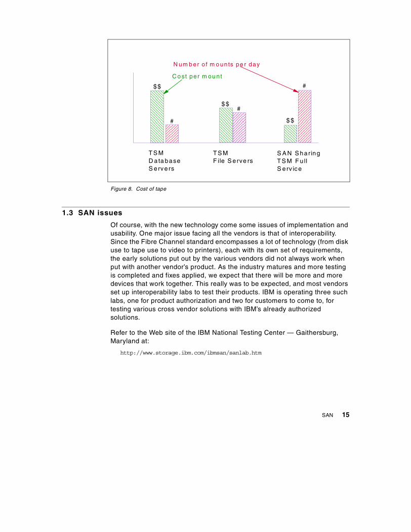
Figure 8. Cost of tape
1.3 SAN issues
Of course, with the new technology come some issues of implementation andusability. One major issue facing all the vendors is that of interoperability.Since the Fibre Channel standard encompasses a lot of technology (from diskuse to tape use to video to printers), each with its own set of requirements,the early solutions put out by the various vendors did not always work whenput with another vendor’s product. As the industry matures and more testingis completed and fixes applied, we expect that there will be more and moredevices that work together. This really was to be expected, and most vendorsset up interoperability labs to test their products. IBM is operating three suchlabs, one for product authorization and two for customers to come to, fortesting various cross vendor solutions with IBM’s already authorizedsolutions.
Refer to the Web site of the IBM National Testing Center — Gaithersburg,Maryland at:
http://www.storage.ibm.com/ibmsan/sanlab.htm
C o st per m ou nt
T S MD ata baseS erve rs
T S MF ile S erve rs
S A N S haringT S M F u llS erv ice
$$
$$
$ $#
#
#
N um b er o f m o unts pe r day
SAN 15

One major issue that has not been resolved is how to use the various hubsand FC-AL in productive workloads. While testing the SAN Data Gateway,IBM discovered that an FC-AL hub has to go through LIP processing everytime a node is either brought offline or online to the loop.This LIP processingoften causes the loop to drop an in-transit I/O, which is not a good thing forthe I/O process. In the case of hosts, this happens frequently. Thus IBM hasdecided that for the initial rollout of this SAN product, high-end platforms willnot support the hub with multiple hosts attached to it. Since devices seem tobe much more stable and disruptions of the loop are much less frequent withmultiple devices attached, IBM will support the hub with devices attached tothe gateway, and will support Windows NT hosts.
Sharing of the tape drives, which can now be seen by each of the attachedhosts, can only be effective if software is available to manage the process ofsharing between the servers. The paradigm that has emerged (used byseveral vendors) is to allow one of the servers to be the master and the othera slave. The slave asks the master for permission to use the drive (via theLAN) and when the master knows that the drive is free, permission is granted.Given homogeneous software platforms (all servers being either TivoliStorage Manager, Legato, Veritas, etc.), this sharing can take place acrossheterogeneous hardware platforms.
1.4 Marketplace
Data is the most critical resource in today’s environment. Without data,computer processes would be very uninteresting. Data created today is usedtomorrow and the next day. Thus the amount of data seems to grow withoutbounds in today’s enterprise. This has many causes:
• Dramatically lower costs of storage subsystems
• More complex data formats (see Figure 9), an evolution from:
• Text• Spreadsheets• Images• Presentations• Video
• More complex applications, especially data warehousing applications
16 Storage Area Networks: Tape Future in Fabrics
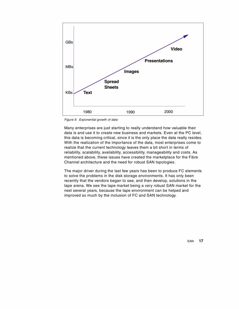
Figure 9. Exponential growth of data
Many enterprises are just starting to really understand how valuable theirdata is and use it to create new business and markets. Even at the PC level,this data is becoming critical, since it is the only place the data really resides.With the realization of the importance of the data, most enterprises come torealize that the current technology leaves them a bit short in terms ofreliability, scalability, availability, accessibility, manageability and costs. Asmentioned above, these issues have created the marketplace for the FibreChannel architecture and the need for robust SAN topologies.
The major driver during the last few years has been to produce FC elementsto solve the problems in the disk storage environments. It has only beenrecently that the vendors began to see, and then develop, solutions in thetape arena. We see the tape market being a very robust SAN market for thenext several years, because the tape environment can be helped andimproved so much by the inclusion of FC and SAN technology.
SpreadSheets
KBs
1980 20001990
GBs
MBs
Text
Video
Presentations
Images
SAN 17

18 Storage Area Networks: Tape Future in Fabrics

Chapter 2. SAN opportunities
As we can see from the discussions in the previous chapter, the advent of theFC technology and the SAN topologies will help resolve some fundamentalissues facing those enterprises trying to stretch the limits of the older storagearchitectures. Hardware elements alone cannot solve all the issues; alsoneeded are software management tools to really exploit these technologies.Vendors need to re-evaluate their existing products and possibly redesign thearchitecture to fundamentally use the benefits of the new technology to solvethe problems their older products had tried to solve. By the very nature of animplemented product, it has to adhere to the available technology structure.When a new technology is available, restructuring is necessary in order totake advantage of the features of the technology. Simply patching the oldersoftware solution to work in the newer hardware technology will not yieldmaximum results for the product set. Those vendors who do this fundamentalreadjustment will be the short term winners.
So the question remains as to what kinds of products we can expect as theFC architecture and SAN topologies roll out during the next several years. Inthis chapter, we hope to show some generic solutions, including both thosethat are available today and those we might expect in the future. We will try touse generic terms such as UNIX server, NT server, S/390 server, tape library,backup server solution, etc. You, the reader, can put into the scenarioswhatever product names you wish. Since this redbook is about the future ofSAN technology and tape environments, we felt that this chapter is key tounderstanding why the vendors (and the industry) are pursuing thesesolutions so feverishly.
One should not expect that any one vendor can be the leader in everytechnical area. Rather, you should expect that the vendors will have topartner with others to deliver products to meet the needs of their customers.IBM’s SAN initiative is to utilize all resources at our disposal which willinclude close collaboration with partners as well as integration with otherproducts from competitors. For example, expect that in the future IBM’sbackup product Tivoli Storage Manager will deliver solutions on most otherhardware platforms (just like today). So if Dell, for example, delivers a SANsolution which allows the sharing of tape drives, one might expect TivoliStorage Manager to support the hardware solution as soon as possible.Another example is the FC concept of third-party copy, which enablesserver-free backup. Tivoli Storage Manager will exploit this feature as itbecomes commonplace.
© Copyright IBM Corp. 2000 19

2.1 Solutions available in the near term
This section will discuss the solutions we see currently in the marketplace.We will keep this generic, but in most cases IBM has solutions that meetthese needs. For the most part, this discussion is directed at solutions toproblems, and not the elements used to implement those solutions. In laterchapters, we will present the IBM solutions in detail with real configurations.
2.1.1 Tape connectivityConnectivity to tape is essential for most backup processes. However, tapedrives are expensive, and tape libraries are even more expensive. Study afterstudy shows that automation of the tape process saves money whileincreasing reliability. Tape and disk are fundamentally different, since themedia of the tape is removable, and storable anywhere, away from the tapedrive. This is not the case for disk — the drive and media are locked together.Due to the removability and storability of tape media, enterprises have longhad to utilize staff to remove these tapes, transport them to a storage site,and then return them to the tape drive for mounting when needed. Cutting outeither expensive drives, libraries, or handling is generally the direction ofcustomer tape planning initiatives.
The SAN allows for greater connectivity of the tape library and tape drives,especially at greater distances, and allows for eventual tape sharing. Tapesharing will be discussed in the next section. FC allows for 10 km betweenthe server (or data point) and the connected tape node. This allows for bothgreater sharing and remote tape creation. Disaster recovery will be discussedbelow as well.
The single biggest issue today with tape sharing and remote creation is theSCSI architecture. Most SCSI tape drives currently have only one SCSI portand hence can only be on one SCSI bus. This severely limits the number ofhosts that can physical allocate the drive without recabling. FC enables themultiple host scenario without recabling.
Figure 10 depicts multi-host tape sharing using a SAN. In this case threehosts are connected to a single SAN topology. Also attached to the SAN aresix SCSI tape drives through a bridge or a gateway. If software to manage thesharing is not available, we would need to isolate (or zone) the drives tounique hosts. With the proper management software, each drive can talk toeach host, and the connections can be dynamic without need for anyrecabling.
20 Storage Area Networks: Tape Future in Fabrics
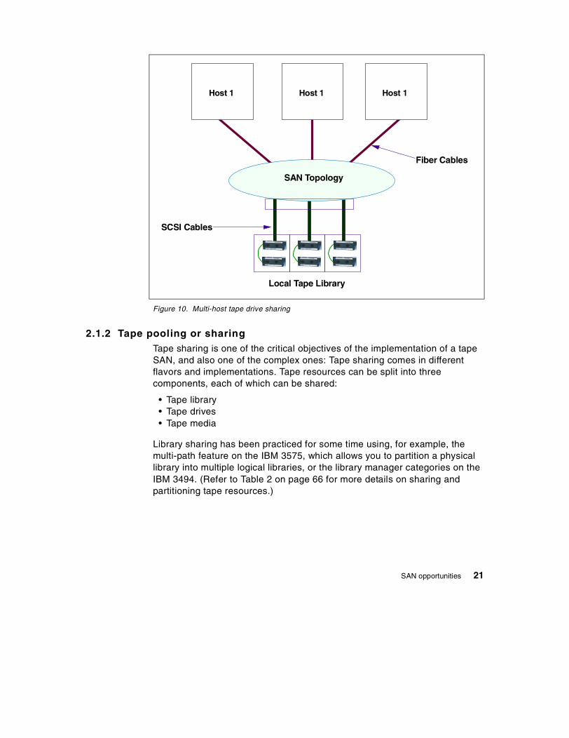
Figure 10. Multi-host tape drive sharing
2.1.2 Tape pooling or sharingTape sharing is one of the critical objectives of the implementation of a tapeSAN, and also one of the complex ones: Tape sharing comes in differentflavors and implementations. Tape resources can be split into threecomponents, each of which can be shared:
• Tape library• Tape drives• Tape media
Library sharing has been practiced for some time using, for example, themulti-path feature on the IBM 3575, which allows you to partition a physicallibrary into multiple logical libraries, or the library manager categories on theIBM 3494. (Refer to Table 2 on page 66 for more details on sharing andpartitioning tape resources.)
Fiber Cables
Local Tape Library
SCSI Cables
Host 1 Host 1 Host 1
SAN Topology
SAN opportunities 21

The SAN allows multi-host connectivity to the drive, but software is necessaryto allow for true sharing. Today most vendors are pursuing a model in whichone server manages the tape resources and the other sharing servers needto ask permission to gain access to the tape resource. The real benefit here isthe sharing of a very expensive resource — the large library and tape drives.
The rule of thumb for sharing resources is that for two systems sharing thesame resource, there will be a reduction of about 20-30% in native resourcerequirements. For example, two Tivoli Storage Manager servers both needingfour Magstar 3590 tape drives and 500 tape slots to manage their individualTivoli Storage Manager workloads would be expected to need only 6 drivesand about 800 slots to manage the same workload if they could share theresources. Thus, if the SAN technology elements and the new levels ofsoftware are not too expensive, as compared to what already exists, thesavings in tape drive resources will generally provide a good economicjustification.
Tape sharing solutions have been announced by several vendors, and thisshould become the launching point for many other more advanced solutionsin the next few years.
Tape pooling is the ability to allow two or more servers to logically share tapedrives within a tape library. In this case, the servers need to be attached tothe same SAN as the tape drives, and there needs to be some softwaremanagement to control who owns the drives and tape cartridges at any onepoint-in-time. Figure 11 shows three backup servers all getting their clientdata through the corporate LAN sharing six tape drives in one library.Software running in the master backup server talks with tape sharing clientcode on each slave backup server to control the allocations of the tapedrives. The only difference between Figure 11 and Figure 10 is the softwarecreated by the backup server solution provider to actually manage the taperesources.
Tape pooling across a SAN will be supported by Tivoli Storage Manager,starting with release 3.7. The nature of the SAN is not critical to this softwaresolution, since the control of the actual access is done through the TivoliStorage Manager management software. Physical access to each tape driveis required, which SAN topology allows.
22 Storage Area Networks: Tape Future in Fabrics

When using a tape library with outboard management, like the IBM 3494, thetape drives can be shared without one of the Tivoli Storage Manager serverstaking the role of the arbiter: The tape drives can be shared using SCSIReserve/Release functions (dubbed auto-share, a Magstar 3590 feature) andthe tape media is controlled by the library and assigned to a specific host,thus eliminating the need to manage the tape inventory using applicationsoftware.
Figure 11. Tape pooling
2.1.3 Tape extension for disaster recoveryAnother important aspect of tape SAN is the exploitation possibilities of tapeconnectivity for disaster recovery enhancements (Figure 12). Today mostenterprises take their tape backups offsite for disaster recovery. The tape isactually created in a locally attached tape library, then ejected from the libraryand finally removed to an offsite location. All of this requires manualintervention and is error-prone. A major reason for failed recoveries is causedby the wrong tape being in the wrong place.
F ib er C a bles
Loca l Tape Library
S C S I C ab les
S A N To p o lo gy
B acku pSe rverM aster
B acku pServerS lave
B ac kup ServerS la ve
C orp ora te LA N
B ack upC lie n ts
B ac ku pC lien ts
SAN opportunities 23

FC SANs allow the backup server to create the tape easily and safely in aremotely attached tape library. This removes all of the manual effort, sinceonce the tape is created the tape is already offsite. Thus, for the disasterrecovery scenario, this removes a major reason for disaster recovery failure.
A real need exists for extending tapes into a remote site. Currently, mostenterprises need to staff the tape operations in order to handle the tapes asthey come and go from offsite storage. Since Fibre Channel allows for greaterdistances, it becomes much easier to put a remote tape library across yourcampus to create the backup tape copy. With this method, no manualhandling is necessary.
Figure 12. Remote tape creation using a SAN
Site 2
Site 1
Remote Tape Library
Local Tape Library
SAN Topology
FC Extenders
BackupServer
Corporate LAN
24 Storage Area Networks: Tape Future in Fabrics
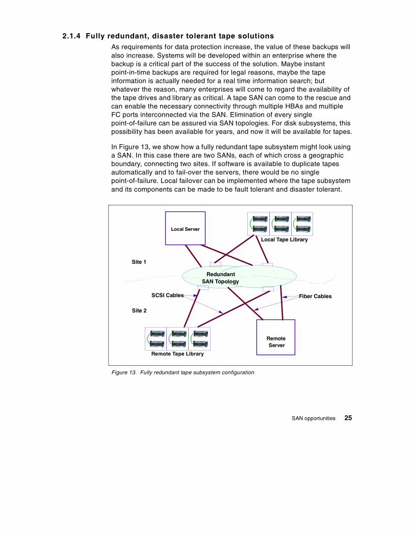
2.1.4 Fully redundant, disaster tolerant tape solutionsAs requirements for data protection increase, the value of these backups willalso increase. Systems will be developed within an enterprise where thebackup is a critical part of the success of the solution. Maybe instantpoint-in-time backups are required for legal reasons, maybe the tapeinformation is actually needed for a real time information search; butwhatever the reason, many enterprises will come to regard the availability ofthe tape drives and library as critical. A tape SAN can come to the rescue andcan enable the necessary connectivity through multiple HBAs and multipleFC ports interconnected via the SAN. Elimination of every singlepoint-of-failure can be assured via SAN topologies. For disk subsystems, thispossibility has been available for years, and now it will be available for tapes.
In Figure 13, we show how a fully redundant tape subsystem might look usinga SAN. In this case there are two SANs, each of which cross a geographicboundary, connecting two sites. If software is available to duplicate tapesautomatically and to fail-over the servers, there would be no singlepoint-of-failure. Local failover can be implemented where the tape subsystemand its components can be made to be fault tolerant and disaster tolerant.
Figure 13. Fully redundant tape subsystem configuration
Site 2
Site 1
Fiber Cables
Local Tape Library
RemoteServer
Remote Tape Library
RedundantSAN Topology
SCSI Cables
Local Server
SAN opportunities 25

Although a fully redundant tape subsystem is not currently available, weplace it in the near term solution portion because, once tape sharing andremote tape creation are available, a redundant subsystem can be built.Advanced features built upon this model will be discussed in the next chapter.
2.2 New opportunities
This section will discuss solutions we have only heard about or expect to see.Some of these are here simply to show that the new SAN topology with theunderlining FC architecture allows us to think about new ways to solve thedata management issues facing our customers today. It is these new potentialsolutions that are causing the keen interest in this arena.
2.2.1 LAN-free backupCurrent LANs are too slow and often clogged. We need to remove the dataflow from these networks so they can perform the interactive transactions thatthey were originally designed to do. Direct connections between the clientand the server have been used in the past to remove the heaviest traffic fromthe LAN. Products like CLIOS and InfoSpeed allow a UNIX or NT client toconnect directly to the S/390 server and move large blocks of data withoutusing the corporate TCP/IP LAN network. These solutions were point-to-pointutilizing the ESCON topology available to the S/390 server. This concept canbe migrated into the general server world via the connection to a SANtopology. Without changing the software in the backup server, a SAN couldbe utilized to move data from the client to the backup server as long as theFC elements supported TCP/IP on the upper layers. However, the HBAvendors have not perfected this interface and the backup server softwarevendors are still waiting.
In addition to these issues, we have already discussed the heavy TCP/IPoverhead within a backup server. No matter how the TCP/IP traffic arrives atthe server, this overhead will exist. However, the FC architecture actuallyenables an even better solution where the data can flow directly from theclient to the tape drive, which can be managed by the backup server. This isthe concept of tape sharing with a software package, as discussed in Section2.1.2, “Tape pooling or sharing” on page 21. There are actually many ways toimplement this type of function but, in general, the tape SAN is crucial to theoperation.
26 Storage Area Networks: Tape Future in Fabrics

Tivoli Storage Manager supports a LAN-free backup mode of operation usingVersion 3.7 or higher. A LAN-free backup is done by a backup server usingthe SAN topology and functions of FC to move the backup data over the SAN,thus eliminating the LAN from the data flow. This does two things: first, theLAN traffic is reduced, and secondly (and most importantly) the traffic throughthe backup server is reduced. This traffic generally is processor-heavybecause of TCP/IP translations. Here the backup server orchestrates thedata movement, manages the tape library and drives, and tells the clientswhat data to move. The client does not have its data on the SAN, but it needsto be connected to the SAN. (See Figure 14.)
Figure 14. LAN-free backup
In Figure 14 we depict a LAN-free backup. Actually, a better term might be aLAN-lite backup, since the LAN is still used to pass meta data back and forthbetween the backup server and the client. However, the actual backup data ispassed over the SAN. The meta data is the data needed by the backup serverto manage the entire backup process, and includes things like the file name,the file location, time of the data movement, where the new copy resides, etc.
BackupServerDisk Pool
Remote Tape Library
Corporate LAN
SAN Topology
Backup Server
SCSI Cables
Backup ClientClientDisk
Fiber Cables
Step 2
Step 1
SAN opportunities 27

This data tends to be small as compared to the actual client data beingmoved.
In Step 1 the backup server talks with the client to determine what data needsto be moved; such as a backup, a restore or an archive. After the backupserver determines what it wants done with the data, it sends the request tothe client. In this case we show a request to move the data to the backup diskstorage pool, such as might happen in a Tivoli Storage Manager environment.The client’s own data is not part of the SAN topology in this case, so the client(in step 2) simply moves the data from its own disk to the backup server’sstorage pool as instructed to do. When the move is complete, the clientnotifies the backup server. This reduces a lot of system processor overheadon the backup server, since for a move through the server, about half of theserver’s processing power is used to process the TCP/IP transaction.
For this example we have assumed that the backup server uses its normal(non-SAN) processes of moving the data from the storage pool to the tape.Later, we will show how this is further improved when the backup serverutilizes the SAN directly for its own workload.
2.2.2 Server-free backupOn June 22, 1999, IBM announced that Tivoli Storage Manager will support aserver-free backup mode of operation in mid-2000. Server-free backup (seeFigure 15) refers to the concept of using a feature which allows a storagedevice to talk to another storage device (such as a disk talking to tapedirectly). A backup server would need to understand what resources areavailable, would need to know where the data to be copied was, and wherethe data was supposed to be delivered. SCSI architecture allows for what iscalled third-party copy, where one SAN node delivers instructions to a secondnode to copy some data from that node to another node. The transactiontakes place outside of the scope of the first node, and at completion, theprimary node is notified of the success or failure of the data movement.
In this case, not only is the LAN not used for data transfer, the backup serveris not even used. Precious I/O bandwidth and processor cycles are saved onthe backup server and the client server. Many vendors are promising thisfunctionality, and we expect to see this generally available from severalvendors during the year 2000. This really will be a major evolution for thebackup process.
28 Storage Area Networks: Tape Future in Fabrics

Figure 15 is a rather complicated diagram showing the flow of data for anexample of a server-free backup. This diagram is not intended to representthe way in which Tivoli Storage Manager will implement this feature, butrather to illustrate how one could implement the feature. In this case, neitherthe client nor the backup server is directly involved in the movement of thedata. We have shown an example of a third-party copy where the meta-datafor the actual move is passed to a data move manager (DMM), which isactually part of the SAN Topology (probably residing inside the switch or thegateway). The backup server works with the client to determine where thedata should go, as we showed in Figure 14 on page 27, but now after the datais moved into the disk storage pool of the backup server, the power of theSAN is invoked.
It needs to be pointed out that the "data move manager" is a generic termcoined by this redbook team and not intended to represent an actual productby any vendor. The term third-party copy is a standardized feature working itsway through SNIA and requires the new SCSI-3 protocol. This SCSI-3protocol is being developed expressly to be used in FC environments.
This example shows the client’s disk still attached directly to the client. If thedisk was attached to the client through this SAN, the backup server couldactually initiate, through the DMM, a third-party copy of the data between thedisk of the client and the storage pool of the backup server.
SAN opportunities 29

Figure 15. Server-free backup
• Step 1 — The backup server communicates with the server to determinewhat needs to be done; such as a recall, a backup, or an archive.
• Step 2 — The backup server communicates with the client to tell it to movethe data (in this case) to the backup server’s storage pool.
• Step 3 — The client moves the data from its own disk to the backupserver’s storage pool.
• Step 4 — At a later time, the backup server decides to move the data totape.
• Step 5 — The backup server readies the tape drive, mounts the tape, andpositions it.
BackupServerDiskPool
RemoteTapeLibrary
Step6
CorporateLAN
SANTopology
BackupServer
SCSI Cables
BackupClientClientDisk
Fiber Cables
DataMoverManager
Step5Step3
Step2Step1
Step7
Step4
30 Storage Area Networks: Tape Future in Fabrics

• Step 6 — The backup server sends the third-party copy meta-data to thedata move manager (DMM), which is located in the SAN topology.
• Step 7 — The movement of data is done without the involvement of thebackup server by the DMM using the third-party copy feature.
• Step 8 — Notify the backup server of completion.
2.2.3 A new paradigm for a backup server using a SANIn this section we will describe what the backup server of the future may looklike, using an internal SAN. Creating such a server might actually be easierthan creating servers that support LAN-free backup and/or server-freebackup in a heterogeneous environment. For a single backup server, using aprivate SAN removes many of the issues of heterogeneity and establishes ahomogeneous environment. We have assumed that the FC features ofthird-party copy and multicasting are used across this private SAN. Oncethese features are standard, we would expect the backup server vendors tocreate a server model like that shown in Figure 16.
We believe that the backup server vendors will need to exploit the SAN bothinternally and externally. For the next several years, large, complex SANs willbe difficult to build, maintain, and manage. Therefore, we would expect thatexternal SAN connections to the backup server will be reserved for selectedlarge scale clients. Smaller clients will continue to pass their backup dataover the LAN to the backup server. Thus the need for the backup server,especially a Tivoli Storage Manager backup server, to move data betweendisk and tape, and tape and tape, will remain. Removing this internal datamovement from the Tivoli Storage Manager server will be of great importanceto reduce the load on the server and increase its scalability.
SAN opportunities 31

Figure 16. A new paradigm for the backup server using an internal SAN
In Figure 16, there are only three data movement steps even though there arefour data movements. Steps 1 and 2 are managed by the backup server andthe data flows through this server. Thus this is not classified as a LAN-free orserver-free backup model. For smaller clients this will probably be theparadigm for a long time to come. However, by utilizing the concept of theDMM, Step 3 is managed by the SAN and reduces the workload on thebackup server. Step 3 is classified as a third-party copy with multicasting. Thebackup server tells the DDM what to do and the DMM does the actual datamovement. In this case making a remote copy of the tape data at the sametime as the local copy. Thus two data movements are done in this one step.
BackupServer
SAN Topology
LocalTape Library on the SAN
Disk Poolson the SAN
Fibre ChannelData MoverManager
RemoteTape Library on the SAN
Data Move #1
Data Move #3 Data Move #3
Data Move #2
Backup Complex
Corporate LAN
BackupClients
BackupClients
32 Storage Area Networks: Tape Future in Fabrics

2.2.4 Complex backup scenariosThe FC architecture allows for a SCSI-3 protocol feature called multicasting,where one FC command can direct the same output to two separate anddistinct FC nodes. Thus, for the disaster recovery scenario, when coupledwith the server-free backup depicted above in Figure 16, the tape local andbackup copy can be made via one set of commands which uses no LANbandwidth, backup server, or client resource, but rather utilizes an element ofthe SAN and the bandwidth of the SAN.
In this case, the backup is managed via a backup server. Data movement isdone by a function of an element in the SAN. Backups are taken as they aretoday, but over a high speed transport, and tape copies are made bothremotely and locally to satisfy disaster recovery requirements. See Figure 17.
Figure 17. Server-free backup with client’s disk on SAN and multicasting
BackupServerDisk Pool
Local Tape Library
Step 6
Corporate LAN
SAN Topology
Backup Server Backup Client
ClientDisk
Fiber Cables
Data MoverManager
Step 5
Step 3
Step 2Step 1
Step 7
Step 4
Remote Tape Library
SAN opportunities 33
• Step 1 — The backup server communicates with the server to determinewhat needs to be done; such as a recall, a backup or an archive.
• Step 2 — The backup server communicates with the client to tell it to movethe data (in this case) to the backup server’s storage pool.
• Step 3 — The client (or the backup server) moves the data from theclient’s disk to the backup server’s storage pool using third-party copy.
• Step 4 — At a later time, the backup server decides to move the data toboth a remote tape and a local tape.
• Step 5 — The backup server readies both tape drives, mounts the tapesand positions them.
• Step 6 — The backup server sends the third-party copy meta-data to thedata move manager (DMM) with the multicasting feature enabled so as toinvoke the dual movement of the data to both tape drives.
• Step 7 — The movement of data is done without the involvement of thebackup server by the DMM using third-party copy feature of FC. Bothtapes have the same data and look alike at this point.
Figure 17 depicts a very advanced backup server and client, both of whichcan take advantage of the SAN topology and FC architecture. Here thebackup server works with the client to determine which data to move. Then,instead of the client actually doing the move, either the client or the backupserver could send a request to the DMM, which would do the movement ofthe data from the client to the storage pool of the backup server. At a latertime, the backup server then uses third-party copy and multicasting to movethe data from the storage pool to two distinct tapes in two libraries at twosites. This is very advanced, because with this one set of commands, boththe primary and backup copy are made to two tapes, and one is alreadyoff-site.
As an initial starting point, we would expect that the backup server will usethe SAN technology first to deal with its own internal work. Due to the currentsize restrictions of switches and gateways, we would not expect a completeserver-free solution for a while. However, the FC concept can be utilized bythe backup server, and especially for a disk based system, like Tivoli StorageManager, the movement of data along the SAN topology using third-partycopy and multicasting can reap great benefits.
34 Storage Area Networks: Tape Future in Fabrics

Figure 14 on page 27, Figure 15 on page 30, Figure 16 on page 32 andFigure 17 on page 33 have all depicted the backup server using the SANfunctions of third-party copy. This relieves the burden of moving data from theserver. All of these examples are things we might expect to see over the nextfew years. It is unlikely that these features will be available in the short term,since the rough edges of FC architecture and SANs still need to be smoothedover. Customers may want to begin planning with their backup vendor whatthe future will look like for them. Some vendors will lead and some will follow— IBM has made it clear that Tivoli Storage Manager will be leading the SANcharge. Over the next few years the vendors will begin to push out solutionsthat will exploit the SAN technology much like we have shown in thesediagrams. You, as a customer, will probably need to begin to understand theimplications to your environments, because these types of solutions arecoming.
2.2.5 A new architecture for the backup serverThe SAN attachment of the tape, the backup server, the larger clients, andthe disk pool will allow (actually force) vendors to take another look at theirproducts. We might see that the data movement is separated from the backupserver inventory database. Today the backup server does three things: itmanages the backup process and understands where the data is, managesthe tape subsystem and media and understands what to mount, and movesthe data. The SAN enables these three functions to be de-coupled and evenmoved into different servers. One server would need to be the brains andunderstand where things are and understand how to get them. A secondserver could manage the entire tape subsystem, the Tivoli Removable MediaManager server. A third server could manage the actual data movements,probably using FC third-party copy functions, as well as standard datamovement functions. See Figure 18.
SAN opportunities 35

Figure 18. Backup architecture of the future using a SAN
2.2.6 Intelligent tape subsystems (ITS) and SAN — is this the future ?The IBM Magstar Virtual Tape Server (VTS) has been enhanced to supportattachment to SCSI host systems, currently limited to AIX. In addition, directFC connection to the VTS will be allowed in the future, with FC attachmentusing the IBM SAN Data Gateway to be made available first.
The question has been asked repeatedly: why use a VTS for Open Systemsconnection? Clearly the issue of stacking small tapes onto larger tape mediais more likely to be an S/390 issue, and clearly this was the major intent forthe original VTS. But the current VTS is much more robust and has muchmore performance, and therefore can handle much bigger workloads.Virtualization saves real resources and, if the performance can be made goodenough, can be used to reduce real costs to the enterprise.
Backup Clients on the SAN
Corporate LAN
BackupClients
BackupClients
Tape Libraries on the SAN
Priv
ate
LAN
SAN Topology
TapeSubsystem
Manager
BackupServer
InventoryMaster
Data MoverManager
Disk Poolson the SAN
36 Storage Area Networks: Tape Future in Fabrics

Let us examine the VTS in much more detail to see how it could help solvesome of today’s tape issues, and hence why it might be a good candidate toconnect to a SAN topology. VTS is basically a system that appears to theuser like many tape drives with many tape media volumes, but in reality it is avery large disk cache (to accept the data quickly from its clients), with enoughreal drives to off-load the cache when necessary and enough tape cartridgesto store the logical volumes. If we recall some of the issues of tape versusdisk (that tape is expensive to write to, but cheap to retain data on) and wemap that to the way a VTS works, we see that if the disk cache was largeenough to handle most of the tape recalls and expirations, then we would beputting tape data on disk for a short while (6-10 days) and then to tape for avery long while (over 30 days).
This method really maximizes the effectiveness of the two types of storage,without the client knowing, or caring, what is being done. Data kept for lessthan 10 days, which tends to include most of the active data and thedatabases, would really be going to disk, and not to tape, while data needinga long life would pass through the relatively inexpensive disk on its way to thereal tape media. SInce most backup data is recalled in the first 10-14 days, ifthis data could somehow be in cache, no tape mounts would be required. So,properly configured, a VTS can be used to reduce the expense of tapemounts while giving a performance boost.
Since the VTS is based on IBM storage, the RS/6000 AIX processor, andTivoli Storage Manager software, we should anticipate that a naturalprogression for the VTS is to incorporate the SAN technology under thecovers. What does this do? It allows the VTS to continue to become evenmore robust, with even faster working pieces and larger storage caches andfaster tape drives. As this becomes more expensive, we would really want tobe able to share it. That is where the SAN comes in. Therefore, if the VTScontinues to grow in robustness, size, performance, and features, the needfor it to connect to a SAN will also intensify.
Can backup software solutions really use the VTS? Yes, in fact, the VTS isused in many Tivoli Storage Manager installations today. It is not necessarilythe best fit today, but for individual enterprises the relatively low cost ofsharing the Tivoli Storage Manager workload within a VTS with the otherS/390 workload overshadows the cost of added native 3590 tapes whichmight make a better technical fit. For the other backup solutions, which do notuse a disk cache, the use of a robust VTS could be a benefit. These othersolutions work much better when the number of drives is increased — andthis is precisely what the VTS creates. These solutions might actually workbetter with a VTS with 64 logical virtual drives (backed up by 1TB of disk andsix 3590s) than with 16 or 32 real DLT tape drives.
SAN opportunities 37
Note: In order to differentiate the current IBM VTS product from possiblefuture implementations, in this redbook we will call the VTS of the future theIntelligent Tape Subsystem, or ITS.
Can we develop other solutions, given plenty of tape and media access, quickrecall times, and low overall costs? Would vendors discover new applicationsfashioned around an intelligent tape subsystem connected to lots of serversvia the SAN? Could information retrieval systems currently utilizing opticalstorage devices be better served by the SAN-based ITS?
In Figure 19 on page 39, we have depicted what we might see in the futurewhen vendors couple the concepts of intelligent tape subsystems with SANtechnology. (Note that the current VTS marketed by IBM should not beconfused with what we are showing here. IBM has not announced anythinglike this, nor would we expect to see this level of solution for several years.)In this case, intelligent tape subsystems are actually managed by anintelligent tape subsystem manager. Note that intelligent tape subsystemsutilize a SAN to better use the real hardware. In this picture we have shownthe subsystems sharing one real library at a remote site. Functions likethird-party copy and multicasting would certainly be employed.
We would expect that new features may be developed that will enhance thispicture even further. The net result is that the attached S/390 or OpenSystems hosts (Host 1,2, and 3) believe that they are talking to real tapes, butthey are really only talking to the intelligent tape subsystem. It is only the ITSthat understands the physical relationship of the drives and tape media to thelogical relationship presented to the tape client. This is analogous to theintelligent disk subsystems of today. Thus different physical environmentscan be maintained which might include a dual copy of each tape at a remotesite without the real tape clients needing to know what is happening.
38 Storage Area Networks: Tape Future in Fabrics

Figure 19. A SAN based virtualized tape subsystem for the future
As these robust ITS are developed, the tape processing world will never bethe same again. The logic of moving data to tape or disk will becomeunnecessary, since the ITS creates the best of both worlds. Data is moved tothe ITS, where it will actually reside initially on disk. After a while. it migratesto tape. However, if the data has a short life it may never make it to the tapeenvironment. Thus cheap disk is used for short term storage and cheap tapeis used for long term storage. Clearly it is the coupling of these twotechnologies (SAN and ITS) that allows this explosion in exploitation. Againwe would caution the reader that these types of solutions are not yet aroundthe corner. Work with IBM to understand the power of these technologies andbegin to position yourself for this future.
Fiber Cables
Local Tape Library
SCSI Cables
Host 1 Host 1 Host 1
SAN Topology
SAN opportunities 39

40 Storage Area Networks: Tape Future in Fabrics

Chapter 3. SAN solutions
This chapter is a review of the IBM products and intentions in the SAN area.We begin with a general overview of the IBM SAN Initiative statements, whichsummarize the IBM vision for SAN. Then, we provide a section for eachindividual area of the SAN Initiative, in which we describe each product orintention of IBM for that area.
3.1 IBM SAN Initiative
In this section, we give you an overview of how IBM intends to providesolutions and products in the SAN world.
IBM formally announced its SAN Initiative on February 17, 1999, and June22, 1999. See Press Releases at:
http://www.storage.ibm.com/ibmsan
These announcements outline IBM’s vision and intent on providing solutionsfor the SAN environments:
“Connectivity, management, exploitation and services make up thefoundation of IBM SAN deployment. SANs combine connectivity hardware,such as Fibre Channel hubs, switches, and gateways, with softwaremanagement that accommodates both IBM and non-IBM products andsoftware solutions exploiting the storage, access, flow, and protection ofinformation seamlessly, any time, anywhere. Leveraging its extensive ITplanning, design, and implementation experience, IBM will provide thesupport, services, and education required to support end-to-end SANsolutions.”
Figure 20 outlines five key promises of IBM’s SAN Initiative:
1. Hardware base (servers and storage)
2. Connectivity
3. Management
4. Exploitation
5. Support
© Copyright IBM Corp. 2000 41
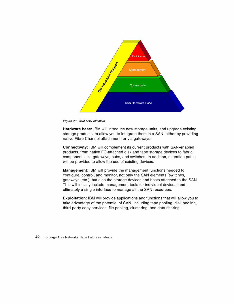
Figure 20. IBM SAN Initiative
Hardware base: IBM will introduce new storage units, and upgrade existingstorage products, to allow you to integrate them in a SAN, either by providingnative Fibre Channel attachment, or via gateways.
Connectivity: IBM will complement its current products with SAN-enabledproducts, from native FC-attached disk and tape storage devices to fabriccomponents like gateways, hubs, and switches. In addition, migration pathswill be provided to allow the use of existing devices.
Management: IBM will provide the management functions needed toconfigure, control, and monitor, not only the SAN elements (switches,gateways, etc.), but also the storage devices and hosts attached to the SAN.This will initially include management tools for individual devices, andultimately a single interface to manage all the SAN resources.
Exploitation: IBM will provide applications and functions that will allow you totake advantage of the potential of SAN, including tape pooling, disk pooling,third-party copy services, file pooling, clustering, and data sharing.
SAN Hardware Base
Connectivity
Management
Exploitation
Serv
ices
and
Supp
ort
42 Storage Area Networks: Tape Future in Fabrics
Services: IBM support structure and services will provide the necessarysupport for the implementation of SANs in the enterprise. This includeseducation, consulting, installation, and maintenance services, as well asinteroperability testing facilities.
These functions will be introduced in a staged manner. Some will beimplemented using non-IBM developed products, notably for the SAN fabriccomponents. For instance, the IBM SAN Data Gateway is a product fromPathlight Technology, and the IBM SAN Fibre Channel Switch is a productfrom Brocade Communications Systems.
See product information at:
http://www.storage.ibm.com/hardsoft/products/sangateway/sangateway.htmhttp://www.storage.ibm.com/hardsoft/products/fcswitch/fcswitch.htm
Also, transition products (gateway products allowing to attach SCSI or SSAdevices to a SAN) will be provided, to allow the integration of existing storagedevices in SAN.
IBM is in a unique position to provide comprehensive SAN solutions, as thereare not many companies on the market who can address all the elements ofSAN, including support and services.
The IBM offerings will be open, and you will be able to integrate non-IBMhosts, devices, and applications, which is one of the main goals of SANs.
3.2 IBM SAN Hardware Base layer
In this section, we describe the products that are part of the SAN HardwareBase layer (Figure 21) of the IBM SAN Initiative. Here we talk about storagedevices that can be attached, one way or another, to a SAN, concentrating ontape drives, of course, as they are the subject of this book.
The equipment on the other side of the SAN, namely processors, are alsopart of this Hardware Base layer. We are not describing host systems in thischapter, except to mention that these can be UNIX or NT machines, using theFCP protocol (SCSI), or mainframe S/390 systems talking FICON over FibreChannel.
SAN solutions 43

Figure 21. SAN Hardware Base layer of IBM SAN Initiative
3.2.1 IBM Magstar MP Product LineThe IBM Magstar MP 3570 Tape Subsystem is a midrange tape storagesolution line of products that has the peculiarity of offering very fast accesstimes to tape data.
This is possible in part because of the patented Magstar MP Fast AccessLinear Tape Cartridge. The cartridge contains a self-enclosed tape path thateliminates time-consuming and cumbersome tape threading, loading, andunloading. In addition, the tape features an innovative new midpoint loaddesign that dramatically reduces random search times.
The way this is achieved is by using a two-reel cartridge type. The MagstarMP 3570 attaches to AS/400, RS/6000, HP, Windows NT, Sun, and otherSCSI-attached systems.
The Magstar MP 3570 can be integrated in a small library with a capacity of20 cartridges slots and two drives, or 140 GB of data (420 GB with a 3:1 datacompression ratio), or in a medium size tape library, the IBM Magstar 3575,which comes in several models, the largest one having a capacity of 320cartridges slots, equivalent to 6.7 TB with a 3:1 compression ratio.
SAN Hardware Base
Connectivity
Management
Exploitation
Serv
ices
and
Supp
ort
44 Storage Area Networks: Tape Future in Fabrics

The Magstar MP drives delivers sustained data transfer performance of7 MB/sec (native) and up to 15 MB/sec per drive or 100 GB/hour pertwo-drive library (with maximum compression).
The Magstar MP can be integrated in a SAN by connecting it to the IBM SANData Gateway. In addition to the increased distance and better cabling, thisallows you to connect the 3570 to more than one host. This is something thatyou cannot do with a normal SCSI connection, unless you put more than onehost on the bus, which is not recommended.
The number of hosts that can be connected to the 3570 is now a function ofthe SAN Data Gateway capabilities; currently, the limit is four hosts (thegateway has a maximum of four Fibre Channel ports). When the 3570 isattached to a router or a switch, you will be able to connect more hosts.
The Magstar MP 3575 library, if it has more than two drives, and dependingon the library model, can be partitioned logically in up to 3 libraries, each onehaving a fixed number of cartridges slots. In a SAN environment, thisfunctionality does not change. Through its inherent partitioning function, the3575 library is especially suited for SAN environments, since SAN offersfurther connectivity and distance possibilities. So you can statically share thislibrary between up to three hosts, which can be on different locations in yourenvironment. Additionally, you can connect the library to even more hosts in aSAN environment and switch the logical libraries simply by reconfiguration ofthe SAN components.
3.2.2 IBM Magstar 3590 Product LineThe IBM Magstar 3590 tape subsystem is a family of tape drives designed toprovide high capacity, high performance, high reliability, and connectivity for awide range of hosts. The Magstar 3590 models B11 and B1A read and writein 128-track format. While reading or writing 16 tracks at a time, the Magstar3590 uses serpentine, interleaved, longitudinal recording technology to makea total of four round trips from physical beginning to physical end of the tapeand back again. The tape read/write head indexes, or moves vertically, whenit completes each round trip so that the recorded tracks are interleavedacross the width of the tape.
The Magstar 3590 uses a metal particle medium in the tape cartridge that canstore 10 GB of uncompacted data. The integrated control unit uses acompaction algorithm that can increase the storage capacity of a singlecartridge to 30 GB.
SAN solutions 45
The Magstar 3590 Models E11 and E1A provide increased capacity andimproved performance over the B11 and B1A. The E models have a nativedata transfer rate of 14 MB/sec, which is an increase of over 50%. In addition,the new models write in 256 track mode and double the capacity of thestandard 3590 cartridge to 20 GB (uncompressed). Finally, the Magstar 3590cartridges are read compatible with the E drive models. This means that anycartridge written by the B models can be read by the new E models.
IBM is providing investment protection to existing Magstar 3590 customers bymaking the existing B drive models upgradeable to the new E models. Inaddition, the B models have been repriced to make them exceptionallyattractive to customers who may not need the added capacity andperformance of the new E models.
The Magstar 3590 tape drive can be connected to a SAN using the SAN DataGateway. The 3590 offers a particularity not found on most of the other tapedrives: each drive has two SCSI ports, allowing it to be connected to twodifferent hosts. The twin-tail feature of the 3590 extends the number of hoststhat can be connected to a 3590, as it can be reached through two SAN DataGateway boxes, and the unique 3590 auto-share feature allows reservation ofthe drive on the device level.
3.2.3 Fibre Channel RAID Storage ServerThe IBM Fibre Channel RAID Storage Server is a robust storage solution forenvironments that require Fibre Channel attachment. This storage systemcan be attached to servers running AIX*, Sun Solaris, HP/UX, Windows NT**,or Novell NetWare — and it can be shared simultaneously by two operatingsystems, such as UNIX** and Windows NT. Multiple server attachments canbe implemented via the attachment of the IBM SAN Fibre Channel Switch orthe IBM Fibre Channel Storage Hub.
For enterprises with multiple platforms that share a storage system, thisconfiguration can help protect storage and server investments whilepotentially reducing the overall cost of ownership. The Fibre Channel RAIDStorage Server supports heterogeneous environments by enabling eachRAID controller to work independently.
3.2.3.1 High-availability designThe Fibre Channel RAID Storage Server has dual-active RAID controllersthat provide high throughput and redundancy. Both controllers can besimultaneously active to provide seamless failover capability in case ofemergency.
46 Storage Area Networks: Tape Future in Fabrics
To increase availability, each RAID controller supports up to 256 MB ofbattery-backed cache and can mirror write operations. Dual fans and powersupplies further support 24x7 operations.
3.2.3.2 Extended distancesThe IBM SAN Fibre Channel Switch and the IBM Fibre Channel Storage Hubprovide greater flexibility and extended distances across Fibre Channel SANtopologies — enabling the Fibre Channel RAID Storage Server to beconfigured at distances of up to 500 meters via short-wave fiber connectionsor up to 10 km via long-wave fiber connections.
3.2.3.3 High performanceThe Fibre Channel RAID Storage Server has dual Fibre Channel ports thatprovide an aggregate bandwidth of 200 MB/sec. With dual Fibre ChannelWindows NT hosts, sustained data transfer rates of up to 179 MB/sec can beachieved with 256 KB sequential reads (up to 190 MB/sec for 256 KBsequential writes for 100 percent cache hits). Approximately 16,200 I/Ooperations per second may be reached with 4 KB 100 percent cache hits incertain environments.
3.2.3.4 Dynamic managementThe StorWatch Fibre Channel RAID Specialist is a network-based integratedstorage management tool that helps storage administrators configure,monitor, dynamically change, and manage multiple Fibre Channel RAIDStorage Servers from a single Windows** 95 or Windows NT workstation.High availability and full redundancy are provided with the host-specific FibreChannel Storage Manager software, which resides on the host system andprovides automatic I/O path failover when a host adapter, IBM SAN FibreChannel Switch, IBM Fibre Channel Storage Hub, or a storage controller fails.See product information at:
http://www.storage.ibm.com/hardsoft/products/fcss/fcss.htm
3.2.4 Enterprise Storage ServerThe IBM Enterprise Storage Server, a second-generation Seascape diskstorage system, was designed from the ground up to support a new approachto disk storage in networked computing environments — one that is widelyaccessible, extraordinarily responsive, and centrally managed. Withconcurrent support for virtually all platforms, advanced performance features,a snap-in design offering easy and quick upgrades, and extremely scalablecapacity, the IBM Enterprise Storage Server is one of the most powerful andversatile disk storage solutions available.
SAN solutions 47

While architected for today’s most demanding applications, the IBMEnterprise Storage Server also is designed to easily integrate into your SANimplementations. See product information at:
http://www.storage.ibm.com/hardsoft/products/ess/ess.htm
3.2.5 LTOLTO (Linear Tape — Open) is a joint IBM, HP, and Seagate initiative to createnew de-facto tape standards in the Open Systems markets. The groupdeveloped the formats to serve multiple market areas and to be supported bymultiple suppliers. These formats provide customers with a clear andstraightforward technology road map, destined to have broad industrysupport.
Licenses are available to all manufacturers for the two formats based on thetechnology: Ultrium™, a high-capacity, single-reel implementation that offersup to 200 GB of capacity assuming a 2:1 compression ratio (100 GB native)and Accelis™, a fast-access, dual-reel implementation that offers dataretrieval in under 10 seconds.
Magstar technologies are at the foundation of the LTO specifications. Thisincludes the extension of the Magstar method of writing data, the linearserpentine Magstar track recording, an enhanced servo tracking mechanismbased on the Magstar MP servo system, a compression scheme derived fromthe same algorithm as the Magstar LZ1 algorithm, error correction codebased on the Magstar architecture, magnetically sensitive highly stable MetalParticle media used in Magstar today, and the implied use of MR headsalready in the Magstar products.
The important fact regarding SAN solutions is the native Fibre Channelinterface that will be available on products of the LTO format. This enhancesconfigurations and it is not necessary to use a gateway. The device can bedirectly attached to switches for easier fan-out.
Figure 22 shows the two LTO Tape Formats.
48 Storage Area Networks: Tape Future in Fabrics

Figure 22. LTO tape formats
UltriumThe Ultrium tape format is the implementation of LTO technology optimizedfor high capacity and performance with outstanding reliability, in either astand-alone or an automated environment. The Ultrium tape format uses asingle reel cartridge to maximize capacity. It is ideally suited for backup,restore, and archival applications. They will load in a manner similar to DLTand will fit in DLT automation slots.
Following you will find some specifications of the Ultrium tape format:
• The first generation of Ultrium allows for 100 GB native capacity in a singlecompact cartridge. The cartridge is smaller than existing single-reel tapecartridges.
• Ultrium provides for data transfer rates of 10-20 MB/sec with the 8-channelhead version and 5-10 MB/sec with the 4-channel head version.
• Ultrium provides for 4 different cartridge capacities (10 GB, 30 GB, 50 GB,and 100 GB).
• LTO-CM (Cartridge Memory) enhances functionality by providing aredundant file log as well as user defined information. A nontouchingexternal reader allows immediate access to that information withouthaving to insert the cartridge into a drive.
ACCELIS ULTRIUM
SAN solutions 49

AccelisThe Accelis tape format is the implementation of LTO technology optimizedfor fast access to data, with exceptional reliability and performancecharacteristics. It uses a two-reel cartridge that loads at the middle of thetape to minimize access time. The Accelis tape format is targeted atautomated environments and can enable a wide range of “on-line” datainquiry and retrieval applications.
• The first generation of Accelis allows 25 GB native capacity. Self-enclosedtape path in the cartridge eliminates tape threading, which greatlyimproves time to first data byte.
• Cartridges are loaded in the middle of the tape rather than at thebeginning, reducing average search time for random files.
• Accelis provides for data transfer rates of 10-20 MB/sec with the 8-channelhead version or 5-10 with MB/sec with the 4-channel head version in thefirst generation.
• Accelis is ideal for library use, with high-speed access to relatively shortfiles. Accelis is suited for applications like data mining and image retrieval,as well as traditional backup/restore.
• LTO-CM (Cartridge Memory) enhances functionality by providing aredundant file log as well as user-defined information. A nontouchingexternal reader allows immediate access to that information withouthaving to insert the cartridge into a drive.
Refer to these Web sites for technology and product information:
http://www.storage.ibm.com/hardsoft/tape/lto/lto.htmhttp://www.storage.ibm.com/hardsoft/tape/lto/prod_data/g225-6847.html
3.3 IBM SAN Connectivity layer
This section describes IBM SAN connectivity products (presently announced)that belong to the IBM SAN Initiative Connectivity layer (Figure 23) of the IBMSAN Initiative pyramid. These SAN components are not (yet) at a stagewhere you can safely assume that you can freely use them together and theywill work. In fact, the opposite is true: only SAN components that have beentested and verified to work together, from the host to the device, are formallysupported.
50 Storage Area Networks: Tape Future in Fabrics

Figure 23. SAN Connectivity layer of IBM SAN Initiative
For this reason, IBM (and all the other companies) will announce and supportindividual devices only in a precise context, after having validated, ininteroperability labs, that they work properly as a given set of products. Wewill indicate, for each product, the contexts in which they are formallysupported today.
3.3.1 IBM Fibre Channel SwitchThe IBM SAN Fibre Channel Switch offers two models, an 8-port model and a16-port model (IBM 2108 S08 and S16). It uses a non-blocking switcharchitecture, thus delivering multiple, concurrent 100 MB/sec connections.
The IBM Fibre Channel Switch offers also advanced management capabilitiesfor:
• Automatic discovery and registration of host and storage devices
• Intelligent rerouting of connection paths, should a port problem occur.
Other features of the IBM Fibre Channel Switch include:
• A Web browser interface that will help you in configuring and managingthe switch
• Cascading of switches, for scaling to larger configurations and to provideresiliency for high data availability
SAN Hardware Base
Connectivity
Management
Exploitation
Serv
ices
and
Supp
ort
SAN solutions 51

• An option for a second power supply
• Configuration with hot pluggable port Gigabit Interface Converters(GBICs) for shortwave or longwave optical connections of up to 10kilometers
The IBM Fibre Channel Switch supports attachments to multiple hostsystems:
• IBM Netfinity and Intel-based servers running Microsoft’s Windows NT orNovell Netware
• IBM RS/6000 running AIX
• SUN servers running Solaris
The SAN connectivity products and storage systems that can be attachedare:
• IBM SAN Data Gateway with IBM Magstar and Magstar MP libraries, andthe IBM Versatile Storage Server
• IBM DLT tape libraries
• IBM Fibre Channel Hub and Netfinity Channel Hub
• IBM Fibre Channel RAID Storage Server and the Netfinity Fibre ChannelRAID Controller Unit
3.3.2 IBM SAN Data GatewayThe IBM SAN Data Gateway (2108-G07) is one of the first components of theIBM SAN solution that allows an easy migration to the SAN environmentusing Fibre Channel technology. The SAN Data Gateway connects SCSI andUltra SCSI storage devices to Fibre Channel environments. It attaches new orexisting SCSI storage products to SAN using an industry standard FibreChannel Arbitrated Loop (FC-AL) interface. The SAN Data Gateway solvesthree immediate problems:
• The 25m cable length restriction for SCSI — the cable can extend up to500m
• The increased bandwidth demand the Ultra SCSI storage products canplace on the SCSI bus
• The address limitations of SCSI
52 Storage Area Networks: Tape Future in Fabrics
Hub and switch attachment to the gateway are supported as well. The use ofhubs in SAN configurations increases the device connectivity, but hubs havesome issues with multiple hosts on the FC-AL loop such as Loop InitializationProcess (LIP) and arbitration. If a system is turned OFF/ON or rebooted itmight impact the operation of other systems in the FC-AL loop. Manyintegrators will not support multi-host loop at all.
The use of switches increases the host fan-out which means the number ofhost connections of SAN configurations.
The SAN Data Gateway is a protocol converter from FC-AL to SCSI thatcurrently supports the attachment of Magstar MP 3570, Magstar MP 3575and Magstar 3590 to Fibre Channel capable Intel-based servers runningMicrosoft Windows NT.
IBM supports, or will support in the near future, the following additionalproduct attachment to the SAN Data Gateway:
• Magstar MP 3570 Tape Subsystem and 3575 Tape Library Dataserverattachment to RS/6000 AIX servers, and Sun Solaris servers.
• Magstar 3590 Tape Subsystem in a stand-alone environment; in a Magstar3494 Tape Library, and Magstar Silo Compatible Tape Subsystemattaching to Intel-based NT servers, RS/6000 AIX servers, and SunSolaris servers.
It also supports attachment of the IBM Enterprise Storage Server (ESS) toFibre Channel capable Intel-based servers running Microsoft Windows NT,and Fibre Channel capable UNIX servers from Sun.
You should check the actually supported servers, adapters, disk and tapesubsystems on the SAN Data Gateway on:
http://www.storage.ibm.com/hardsoft/products/sangateway/supserver.htm
Sharing the gateway between disk and tape products is currently notsupported or not practical, because:
• The Enterprise Storage Server needs all the SCSI attachments• The levels of the HBA (host bus adapter) driver required for disk and for
tape are different, which makes it impossible to use gateway-attacheddisks and tapes on the same host. This will eventually be fixed, but is anice illustration of an interoperability problem.
The gateway can either be used as a stand-alone table top unit or mounted ina standard 19" rack. The rack can be either the IBM 2101 Seascape Solutionsrack or an industry standard rack.
SAN solutions 53
The SAN Data Gateway is equipped with:
• 4 Ultra SCSI Differential ports
• 1 to 3 FC-AL short wave (500 m) ports and Fibre Channel optic cables
• StorWatch SAN Data Gateway Specialist (included on CD)
Features and functions of the SAN Data Gateway• SAN connectivity:
Creates reliable SAN solutions without needing hubs, switches andbridges. The SAN Data Gateway provides a distance or connectivitysolution for SCSI attached storage devices.
• Heterogeneous systems and storage:
Provides seamless support for different host platforms and multiple devicetypes.
• SAN resource sharing:
Zoning or partitioning enables a simple and effective resource sharingsolution. Zones are created by controlling the access between differentchannels or ports and are implemented with the StorWatch SAN DataGateway Specialist access control function.
• SAN value add functions:
• Supports up to 256 LUNs across multiple interfaces.• Persistent Address Maps are preserved in non volatile memory.• Full awareness of SCSI 3 protocol for disk and tape.• ’SCSI over TCP’ for remote transfer, management and control. SCSI
commands and data are encapsulated in TCP packets.• Support for SNIA Extended Copy Command specification; this is the
basis for Server-free Backup solutions in the future.
• Transparent SAN performance:
The total bandwidth of the SAN Data Gateway is 120 MB/sec; the overallperformance is driven by the maximum available device performance.
• SAN Management:
The SAN Data Gateway is remotely managed and controlled by theStorWatch SAN Data Gateway Specialist.
• SAN Scalability:
The SAN Data Gateway is offered with up to 3 FC ports to provide 3x4configurations.
54 Storage Area Networks: Tape Future in Fabrics

Zoning or access controlThe SAN Data Gateway has the ability to connect to more than one host.In the default configuration, there is no restriction between the channels foraccess to the target devices. Without additional controls, host operatingsystems do not handle multiple systems using the same target devicessimultaneously. The result is corrupted file systems when two hosts try to usethe same disk drives or LUN. Or, tape backup and restore operations mightbe interrupted. Use the IBM StorWatch SAN Data Gateway SpecialistChannel Access options to disable the desired access between the SANConnections and individual SCSI channels.
This Access Control function is also called zoning, and it partitions the SANconfiguration by either allowing or denying access between the FC and SCSIports of the gateway.
Figure 24 shows a zoning example for the SAN Data Gateway with two FCports. In the example we implemented two zones. Zone one with a host on FCadapter 1 sees only the devices attached to SCSI adapter 1 and 2. Zone twocontains a different host attached to FC adapter 2 and the devices attached toSCSI adapter 3 and 4.
Figure 24. SAN Data Gateway zoning
Z o n e 2Z o n e 1
SAN solutions 55

The SAN Data Gateway supports one server per FC-AL adapter inpoint-to-point connections. Each host has to have its own drives or tapelibraries. This means that there is no drive sharing possible at all. To use adrive on a different host requires that you reconfigure the gateway.
Advantages of SAN Data Gateway versus hub• Concurrency: aggregate throughput is not limited to one loop.
• Zoning: access control is available based on FC and SCSI ports.
• Hosts are each point-to-point and they can be heterogeneous.
• Smaller configurations with fewer devices offer lower administration costfor customer and lower service/support cost for IBM (as it is easier toisolate problems).
• It avoids the inherent multi-host issues of the FC-AL loop, such as theLoop Initialization Process (LIP) and arbitration. If a system is turnedOFF/ON or rebooted, it might impact the operation of other systems in theFC-AL loop. Many integrators will not support multi-host loop at all.
Advantages of SAN Data Gateway versus switch• It defers or completely avoids the high entry cost of a switch.
• Smaller configurations with fewer devices offer lower administration costfor customer and lower service/support cost for IBM (as it is easier toisolate problems).
• Interoperability issues with switches: fabric support is limited, resourcesharing requires middleware.
3.3.3 IBM SAN Data Gateway RouterThe SAN Data Gateway Router is a SCSI to Fibre Channel Gateway, with oneFibre Channel adapter and up to two SCSI ports. It is a low-cost solution,compared to the IBM SAN Data Gateway product, which offers up to 3 FC x 4SCSI ports configurations.
The IBM SAN Data Gateway Router (IBM 2108-R03) can accommodateeither UltraSCSI single-ended ports or UltraSCSI differential ports.
The router supports full mapping of SCSI IDs and LUNs between the FibreChannel attached host and the SCSI tape library. Also, a StorWatchSpecialist for centralized configuration and management support is available.
The IBM SAN Data Gateway Router can be attached to an IBM Fibre ChannelSwitch for extended connectivity.
56 Storage Area Networks: Tape Future in Fabrics

Host attachment support initially includes:
• IBM Netfinity and Intel-based Windows NT
Support for UNIX and Novell systems is planned for a later date, and specificinformation on supported configurations will be provided at a later date.
3.3.4 IBM Fibre Channel Storage HubThe IBM Fibre Channel Storage Hub (2103-H07) was announced onFebruary 16, 1999, as part of the IBM Fibre Channel RAID Storage Serverannouncement. See the specification sheet at:
http://www.storage.ibm.com/hardsoft/products/fchub/fchub.htm
It is also part of the IBM Netfinity Fibre Channel Storage Solutions.
The IBM Fibre Channel Storage Hub is a 7-port central interconnection forFibre channel Arbitrated Loop (FC-AL) that follows the ANSI FC-AL Standard.Each Fibre Channel Storage Hub port receives serial data from an attachednode and retransmits the data out of the next hub port to the next nodeattached in the loop. Each reception includes data regeneration (both signaltiming and amplitude), supporting full-distance optical links.
The Fibre Channel Storage Hub detects any loop node that is missing or isinoperative and automatically routes the data to the next operation port andattached node in the loop.
Each port requires a Gigabit Interface Converter (GBIC) to connect to eachattached node. The Fibre Channel Storage Hub supports any combination ofshort-wave or long-wave optical GBIC’s. The GBICs are hot-pluggable intothe Fibre Channel Storage Hub, which means that you can add servers andstorage devices to the arbitrated loop dynamically, without powering off theFibre Channel Storage Hub or any connected devices. If you remove a GBICfrom a Fibre Channel Storage Hub, that port is automatically bypassed.Conversely, if you plug a GBIC into the Fibre Channel Storage Hub, it willautomatically be inserted and become a node on the loop.
Hubs can also be used as distance extenders, in connection with the SANData Gateway, as shown in Figure 25 on page 58. Note that this is anexample of using hubs as distance extenders, but this is not an IBMconfiguration at this date.
SAN solutions 57

Figure 25. Using hubs for greater distances
Today, the IBM Fibre Channel Hub is only supported in an NT environment.
3.3.5 Fibre Channel AdaptersFibre Channel adapters, also called Host Bus Adapters (HBAs), are used toattach host systems to a Fibre Channel network. Several variations arepossible on:
• Type of cable supported: long-wave fiber, short-wave fiber, copper
• Fibre Topology support: point-to-point, loop, switch attachment capabilities
• Protocol support: FCP-SCSI, IP, and SCSI concurrently; other FC-4protocols: IPI, SB-2
IBM has announced two FC adapters:
• The Netfinity Fibre Channel PCI Adapter, which is in fact the Qlogic 2100Fadapter.
• The RS/6000 (TM) Giga Fibre Channel Adapter for PCI Bus (FC #6227),which is the Emulex LP7000 adapter.
• IBM also has announced, as part of the IBM Fibre Channel RAID StorageServer announcement, support for FC Adapters on SUN and HP UNIXservers. See this announcement for detailed technical information.
• The Qlogic 2100F adapter is also available for non-Netfinity Windows NThosts.
Windows NTServer
FC hostadapter
Up to 10 kmUp to 500 m Up to 500 m
MagstarLibrary
SA
ND
ata
Gat
ewaySW
SW
LW SW
FC
Hu
b
SW LW
FC
Hu
b
SW shortwave, single mode cable, up to 10 kmLW longwave, multi mode cable, up to 500 m
SW
58 Storage Area Networks: Tape Future in Fabrics
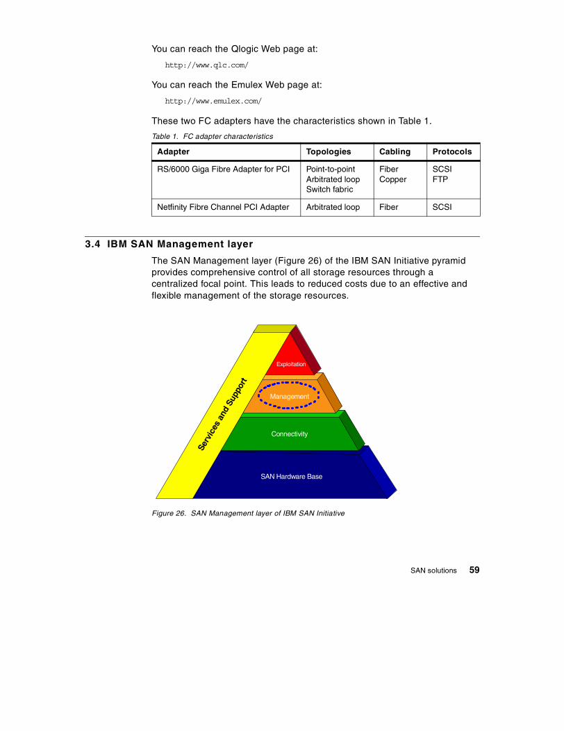
You can reach the Qlogic Web page at:
http://www.qlc.com/
You can reach the Emulex Web page at:
http://www.emulex.com/
These two FC adapters have the characteristics shown in Table 1.
Table 1. FC adapter characteristics
3.4 IBM SAN Management layer
The SAN Management layer (Figure 26) of the IBM SAN Initiative pyramidprovides comprehensive control of all storage resources through acentralized focal point. This leads to reduced costs due to an effective andflexible management of the storage resources.
Figure 26. SAN Management layer of IBM SAN Initiative
Adapter Topologies Cabling Protocols
RS/6000 Giga Fibre Adapter for PCI Point-to-pointArbitrated loopSwitch fabric
FiberCopper
SCSIFTP
Netfinity Fibre Channel PCI Adapter Arbitrated loop Fiber SCSI
SAN Hardware Base
Connectivity
Management
Exploitation
Serv
ices
and
Supp
ort
SAN solutions 59

3.4.1 IBM SAN Management Initiative softwareSoftware for the SAN Management Initiative is needed to configure, controland monitor the SAN and all of its components in a consistent manner. Thissoftware may include management interfaces to individual devices, butultimately will present a single interface to manage all SAN resources.
Currently there is no single generalized tool available to manage all the SANcomponents, but there are already pieces available. Those approaches canbe categorized as follows:
• Device level management
Device level management includes the configuration, monitoring andsimple management of individual Fibre Channel components such asswitches, hubs, and gateways but also individual devices like the IBMEnterprise Storage Server (ESS).
Examples for device level management products are the IBM productsStorWatch SAN Data Gateway Specialist, the StorWatch EnterpriseStorage Specialist and the StorWatch Fibre Channel RAID Specialist.
Examples for switch management tools are the following Brocade softwaretools: Brocade SES (SCSI-3 Enclosure Services) and Brocade Web Tools.
• Total SAN management or SAN level management tools
No total SAN management tools are available so far.
Most of these tools work with GUI interfaces and gather the requiredinformation through either:
• Inband interface:
This is the management of SAN components over the data path throughSCSI protocol.
• Outband interface:
Required data is gathered, for example, through an Ethernet or RS-232serial interface from the SAN component.
IBM approaches a total SAN management solution in the form of a newStorWatch expert component which will be available in 2000. It has acollection of tightly coupled features commonly associated with storagemanagement. The features all rely on a core set of functions provided by theprogram infrastructure and a central database of information collected andanalyzed by each feature.
60 Storage Area Networks: Tape Future in Fabrics

The configuration and management done for the SAN is supplemental to, oran extension of, the configuration and management capabilities of theparticipating operating systems. In other words, IBM's SAN managementsolution utilizes operating system (and FC component) functions asappropriate to implement its functions. The host view, switch view andstorage device views thus become part of a new, higher, SAN view.
The database is a repository for information about the SAN and itscomponents. The information includes but is not limited to device VitalProduct Data, physical configuration, logical configuration, interconnects,state, historical performance, and service data.
SAN level management involves management of the entire switched fabric(and its components and storage devices) as a whole. There are manyaspects of total SAN management. Some of the simpler, lower value functionsinclude:
• Device installation, configuration and monitoring
• Keeping an inventory of resources on the SAN
• Reporting utilities
• Assistance with SAN planning
Some of the more advanced, higher value functions include:
• Automated component and fabric topology discovery
• Managing the fabric configuration including zoning configurations
• Name services
• Managing security
• Health and performance monitoring
• Workload management/balancing of SAN activities based on applicationpriority (for example, backups are lower priority than businesstransactions)
As you can see, SAN management functions differ little from traditionalsystems and storage management functions. As such, IBM's SANmanagement solutions are integrated well with IBM's systems managementsolutions (Tivoli) and storage management solutions (DFSMS, Tivoli StorageManager, StorWatch).
SAN solutions 61

You can imagine a total SAN management solution as a SAN Manageravailable as a further component in the Tivoli software family. This Tivoli SANManager would work together with StorWatch specialist agents on themanaged resources. Figure 27 shows a possible total SAN managementapproach.
Figure 27. Total SAN management approach
3.4.2 IBM StorWatch SAN Data Gateway SpecialistThis section is an introduction to the StorWatch SAN Data Gateway Specialistsoftware, which is working on the device level management in the SANmanagement initiative. See 3.4.1, “IBM SAN Management Initiative software”on page 60 for an explanation of the device level management.
The StorWatch SAN Data Gateway Specialist is a client/server applicationthat helps to manage the SAN Data Gateway with different functions. TheSAN Data Gateway can be implemented and managed also without thissoftware by using the SAN Data Gateway Service Port, but the Specialistallows a central management of all gateways in an installation through a GUIinterfaces and is more user-friendly. The Specialist implements the followingfunctions:
• Asset management:
• Descriptions and product data for gateways, channels, devices• View of current SAN Data Gateway front panel status
• Configuration management:
• Determine current topology; set gateway, channel, and deviceparameters
• Upgrade microcode of gateways from central point
ManagedResourcesWeb Browser
Tivoli SAN Manager(core services)
Expert UI andapplication code
Web Server
SAN Manager
SQLDB
ManagedStorage
Resource
StorWatch Expert
Device ManagementInterface
62 Storage Area Networks: Tape Future in Fabrics

• Device and event monitoring:
• Health checks, set SNMP alert thresholds, eventlog• Error analysis to isolate Fibre Channel and SCSI problems
The IBM StorWatch SAN Data Gateway Specialist can be used to remotelyconfigure and monitor multiple SAN Data Gateways. The Specialist uses acombination of industry-standard SNMP (Simple Network ManagementProtocol) requests for event monitoring, and a method or technology, knownas SCSI, over TCP, which encapsulates SCSI commands and/or data in TCPpackets for gateway management.
Client/Server modelFigure 28 shows how you can implement the IBM StorWatch SAN DataGateway Specialist as a three-part Client/Server model.
Figure 28. SAN Data Gateway Specialist application model
Client
Client
Client
(Java)
(Java)
(Java)
Workstation
Workstation
Workstation
Server
Agent
Agent
Agent
SANDataGateway
SANDataGateway
SANDataGateway
SANDataGateway
Agent Ethernet Network
SAN solutions 63

AgentEach gateway is a stand-alone, SNMP-manageable host. An agentcomponent is embedded in the operating software of the gateway. The IBMStorWatch SAN Data Gateway Specialist uses SNMP as the primary methodof communication with the agent. It allows you to set and retrieve informationthat control the operation of the agent, to update the gateways and targetdevices and manipulate device operating parameters. It also provides alerts(traps) when an event has occurred that requires intervention.
ServerThe Server component is a Java application that runs on a Windows NTsystem. In a simple configuration; the Server and Client can be on the samehost. It is responsible for maintaining communication with the managedagents, and acts as an intermediary between the Agent running on thegateway and multiple Clients. It provides security features by maintainingaccount names and passwords on behalf of the Client application. By keepingtrack of different Client configurations, a user can recall a saved configurationfrom any Client.
The server coordinates the request from multiple clients to manage multiplegateways. All communications between the clients and the server isimplemented using the Java Remote Method Invocation (RMI), a form ofRemote Procedure Call (RPC). The server is written to be both transportableand efficient. Multiple clients can share data the server already knows aboutrather than having to request the data again. In addition, the server receivesall traps from the Agents and forwards them to the clients that have beenregistered to receive them.
ClientThe Client is also a Java application. One or more Clients connect to a Serverin order to manage the gateways. The Client operates from any compatiblecomputer, as long as a Transmission Control Protocol/Internet Protocol(TCP/IP) connection is established to the Server component. This allows fordial-in configurations using Point-to-Point Protocol (PPP), Intranet andInternet access (where allowed by local network policy and firewallconfigurations).
The Client is the application that provides the user interface and allowsviewing and manipulating all gateway and device parameters. Each Client canbe configured by the individual user to show only the gateways of interest.This means that one Client can monitor one set of gateways and othermanagers can be responsible for totally different gateways, without interferingwith each other.
64 Storage Area Networks: Tape Future in Fabrics

The Client uses Java RMI calls to communicate with the server and SCSIover TCP to communicate to the gateways for some operations.
General implementation considerationsThe StorWatch SAN Data Gateway Specialist is a Windows NT basedClient/Server application, running on Windows NT 4.0 Server or Workstation,Service Pack 4 or later. The Windows NT systems for both the Server and theClient component require an Ethernet connection with TCP/IP protocolinstalled. This is required to gather the required data from the gateway. Inaddition to the application components, the Java Runtime Environment (JRE)is installed.
The StorWatch SAN Data Gateway Specialist can be either installed from theCD delivered with the SAN Data Gateway or by downloading the softwarethrough the SAN Data Gateway Internet page:
http://www.storage.ibm.com/SANgateway/
In any case, you should check the Web site for the latest recommendationsfor Operating System, Firmware and the StorWatch SAN Data GatewaySpecialist software.
3.4.3 Zoning or access controlZoning enables resource sharing SAN solutions, but sharing in this case doesnot mean having shared access to the same drives. It is related to thepartitioning of resources. An example is the IBM 3575 Magstar MP TapeLibrary. One logical library in the IBM 3575 could be attached through theSAN Data Gateway to one server, and the second logical library could beattached through the SAN Data Gateway to a different server. The status canbe changed by reconfiguring the SAN Data Gateway, but this is not reallydynamic. The gateway provides additional flexibility in library partitioning,since there is no requirement for recabling, but only for reconfiguration.
Table 2 helps with the understanding of tape library or device sharing /partitioning requirements. Tape Library sharing we consider as partitioning,where as the tape drive sharing is real sharing, having dynamically access toa set of drives from multiple hosts.
SAN solutions 65

Table 2. Library /drive partitioning versus sharing
Zoning is a crucial function for SANs to support. Zoning is required for anumber of reasons. Some operating systems like Windows NT assume thatthey own all devices that they can access; therefore, they must be restrictedfrom accessing devices that are not intended to belong to them. Prevention ofaccess to selected storage nodes from selected hosts may be necessary forreasons such as security, separation of test from production, and contractualobligations for isolation.
3.5 IBM SAN Exploitation layer
The SAN Exploitation layer (Figure 29) at the top of the IBM SAN Initiativepyramid includes the products and functions that will allow you to make gooduse of a SAN. In fact, the availability of these functions, and the value thesecan bring to your enterprise, is certainly the reason for your decision to installa SAN at all.
We start with a section on Tivoli Storage Manager, in which we explain to youhow a backup/restore product can make use of a SAN. Some of theseconsiderations apply to any tape application, including other backup products.
The other theme we review is a generalized tape sharing solution, its goalbeing to allow any application in any environment to access your tape devicesand libraries on the SAN.
Tape library sharing Tape drive sharing
Shared byhomogeneousapplications
Solved by backup application(ARCserve, Tivoli StorageManager*)ORby tape library hardwarepartitioning (IBM 3570, 3575,3494)
Solved by backupapplication (ARCserve,Tivoli Storage Manager)
Shared byheterogeneousapplications
Solved by LibraryManagement MiddlewareORby tape library hardwarepartitioning (IBM 3570, 3575,3494)
Solved by LibraryManagement Middleware(Veritas Media Librarian,Legato SmartMedia,Tivoli Removable MediaManager)
66 Storage Area Networks: Tape Future in Fabrics

Figure 29. SAN Exploitation layer of IBM SAN Initiative
3.5.1 Tivoli Storage ManagerTivoli Storage Manager is the follow-on product to ADSM.
Tivoli Storage Manager can already take advantage of SAN attached disk andtape devices, as the SAN is transparent to the applications (storage devicesbeing viewed as just ordinary SCSI-attached devices), even if someadditional installation considerations apply; for example, to define tape drivesattached across a SAN Data Gateway. These are documented in the DeviceReadme file for the ADSM NT server at level 3.1.2.20.
But to really exploit the new opportunities offered by SAN technologies, thereare some changes, occasional redesigns, and additional functions that willhave to be made to Tivoli Storage Manager. We review here some of thechanges that we should see in the near to midterm future. Some of thesefunctions have already been mentioned, while some of them are morespeculative and merely hint at what it would be possible to do, without anyimplication that these will actually appear in the product in that form.
Please refer to the Tivoli Web site for current product specifications:
http://www.tivoli.com/products/index/storage_mgr/
SAN Hardware Base
Connectivity
Management
Exploitation
Serv
ices
and
Supp
ort
SAN solutions 67

Having Tivoli Storage Manager in a SAN environment provides someinteresting new possibilities (refer to 2.2, “New opportunities” on page 26 foran overview of these functions):
• One special form of “LAN-free” client consists in using the SAN for theTCP/IP traffic between the Client and the Server, as shown in Figure 30.This allows you to take advantage of increased throughput (100 MB/sec)compared to classical LANs, and separates the backup traffic from yourproduction applications using the LAN. In a switched SAN, each sessionwill have the full Fibre Channel bandwidth available. Note that the load onthe client and on the server nodes does not decrease in this scenario, iteven goes up with the increased throughput, as you still need to gothrough the TCP/IP protocol stack on each host.
This function requires support for TCP/IP host-to-host communicationsover Fibre Channel and supported adapter cards.
Figure 30. Client-server transfer over Fibre Channel
• Extended distance for tape devices: this allows you to place your tapedrives outside of the machine room, away from the server. You can makeuse of this for your Primary tape volume and/or for your disaster recoveryvolumes (electronic vaulting). This does not require any additional functionin Tivoli Storage Manager.
• Extended distance for disk units: by having disk units in a remote location,you can place a Tivoli Storage Manager mirror copy of your database andrecovery log on a disk in a remote location, thus allowing you to restartTivoli Storage Manager services very quickly after a disaster at theprimary site. This does not require changes to Tivoli Storage Manager.
data
data
TCP/IP
FC
data
TSM client TSM server
68 Storage Area Networks: Tape Future in Fabrics

• Direct client-to-Tivoli Storage Manager storage pool volume backups andrestores: a client could send its data directly to a Tivoli Storage Managerstorage pool volume, either disk or tape, under control of the TivoliStorage Manager server who would tell the client where (to which disksectors, for example) to write or read that data on the storage pool volume.This is often referred to as LAN-free backup, because the data does notflow through the customer LAN.
The client session initialization and control information flows over LAN,using TCP/IP protocols, but file data flows directly over the SAN, usingSCSI protocols. The big gain here is a decrease of the load on the TivoliStorage Manager server. This requires new functions in both the client andthe server.
• Third-party copy services: SANs allow for third-party copy functions,where data goes directly from one storage device (for instance, a disk) toanother one (disk or tape) without involving any host for the data transfer.The advantages of using these copy services are a reduction in hostoverhead and, possibly, improved performance.
For Tivoli Storage Manager functions, this could be used for:
• Server processes, namely storagepool migration, storagepool backup,and tape reclamation, which would bring a significant reduction of theload on the Tivoli Storage Manager server host.
• Client Sessions: backup, archive, restore, and retrieve traffic would godirectly from the client disk (on the SAN) to server disks or tapes (alsoon the SAN). This would reduce the load on both the client and theserver hosts. This will be of interest only for client data that reside onthe SAN attached disk.
Direct client-to-server transfers open also new opportunities for clientfunctions, like taking a full volume backup of a disk drive without impactingthe client node at all.
Use of third-party copy services will clearly require changes in client andserver code.
• Tape connectivity: being able to connect tape drives to multiple hosts is abig plus if you have more than one Tivoli Storage Manager server host. Itallows you to have essentially as many Tivoli Storage Manager server asyou need, without needing to install drives on each server machine.Reasons for using multiple additional Tivoli Storage Manager server hostsare:
SAN solutions 69

• Load balancing: having two smaller server instances instead of onelarge server allows you to keep the load of the server machine at acomfortable level and/or to keep the Tivoli Storage Manager databasesize to a reasonable amount, all of which helps performance.
• Separate backup and archive servers: separating backup activities,where you typically keep backup versions for a relatively short period oftime (a few weeks) and archive activities, where the retention periodsare normally years, can be very effective in optimizing the TivoliStorage Manager database activities, and in making it easier to treatthese two types of data differently, for example, regarding disasterrecovery.
• Dedicated Tivoli Storage Manager servers: you may need, for instancefor security reasons, a separate Tivoli Storage Manager server for a setof clients or for a specific application. You can now do this, evenmultiple times, without necessarily purchasing additional tape drives.
• Validation servers: many installations have implemented changemanagement policies that require any change to be tested on avalidation system before being installed in the production environment.For validating your Tivoli Storage Manager server, you will need accessto tape drives and libraries, and, thanks to SAN extended connectivity,you will be able to do this without requiring additional equipment, giventhat the tape drive requirements of a validation server are limited intime.
• Server take-over: if you need a stand-by machine for your TivoliStorage Manager server(s), you need also connectivity to the tapelibrary. The extended connectivity you get with SAN allows you to dothis without installing additional drives
• One server per (large) client: for clients having very large databases,SAN tape connectivity and pooling make it possible to have a TivoliStorage Manager server on the same machine as the database, usingany tape drive in the SAN. This is a special case of the dedicatedserver case, mentioned here for performance reasons.
If you already have several Tivoli Storage Manager servers, they probablyhave each a set of tape drives. In this situation, it can happen that a serverneeds, at a given time, more drives than it has, while another server’s drivesare idle. Enhanced connectivity allows to use all your tape drives as one pool,thus obtaining a better overall utilization, and/or requiring a smaller number oftape drives. And if you need fewer tape drives, you may then choose to takethe best technology, rather than having to settle for (relatively) cheap unitsjust because you need many of them.
70 Storage Area Networks: Tape Future in Fabrics

Connectivity of multiple Tivoli Storage Manager servers to tape drives andlibraries implies that something has to manage tape drive assignments tomake sure that no two servers try to use a given tape drive at the same time.This function can be provided either by Tivoli Storage Manager, to allow driveand library sharing between Tivoli Storage Manager servers, or by another,more generalized product, that would provide tape sharing to any application,thus allowing to use the same tape pool for Tivoli Storage Manager and othertape applications.
Unless that tape sharing function is available, you will need to manage theassignments of drives to different servers yourself. For the cases wherechanges of configurations are not very frequent, this can be done by simplyputting the given drive off-line to all the Tivoli Storage Manager serversexcept for the one needing the drive. This would be the case, for instance,with a validation server.
Using Tivoli Storage Manager with the SAN Data GatewayWe now consider a sample configuration of Tivoli Storage Manager serversand Magstar 3590 drives in an IBM 3494 library, and look at how connectingthe tape devices through SAN and the IBM SAN Data Gateway gives youadditional flexibility and better resource utilization. These improvementswould be even greater if considering tape devices other than Magstar 3590,with only one SCSI port per drive. And of course, these same advantages willremain if the tape drives have native Fibre Channel attachments.
The SAN Data Gateway connectivity capabilities allow you to access up tothree hosts from each drive port, or up to six hosts per drive if you use twoSAN Data Gateways, instead of only two host connections per drive.
It also gives you better flexibility for the physical installation of your drives, asyou now have:
• Extended distance: 500 meters versus 25 meters (without extenders)
• Attachment of drives residing on several SCSI busses through one hostFC adapter card, instead of requiring that many SCSI adapters on the host
You can take advantage of these new opportunities by connecting all yourTivoli Storage Manager servers to all the drives installed in your IBM 3494.This allows you to exploit the library drives as one large device pool, insteadof partitioning the drives over the Tivoli Storage Manager servers, as youneed to do in a classical SCSI set-up, where you cannot connect a 3590 driveto more than two systems. (See Figure 31.)
SAN solutions 71

Figure 31. 3590 SCSI connectivity
Compare these two configurations: Figure 31 is typical of an installation thathas two Tivoli Storage Manager server production systems, Tivoli StorageManager1 and Tivoli Storage Manager2, and one test Tivoli Storage Managerserver, Tivoli Storage ManagerT, running on another system, and used as avalidation and test machine for new software levels or for testing proceduresbefore they go on the production servers. In addition, Tivoli StorageManager1 and Tivoli Storage Manager2 are fail-over systems for each other.
In this situation, the connectivity restrictions mean that:
• You cannot connect more than two systems to one given 3590 drive.
• The maximum distance to the last drive on the SCSI bus is 25 meters.Given that you need a cable of 3.4 meters inside the 3494 library todaisy-chain the two drives, this means in practice that you need one SCSIadapter in the host per pair of 3590’s.
• Your IBM 3494 library can be at most 18 meters away from either of yourservers.
The consequences of these restrictions are:
1. Even though your tape load could be satisfied with 4 drives (for example),you need two additional drives to have drives reachable from TivoliStorage ManagerT.
TSM1
TSM2
TSMt
SCSI
3590
3590
3590
3590
3590
3590
72 Storage Area Networks: Tape Future in Fabrics

2. You need two SCSI adapters on Tivoli Storage Manager1, and three onTivoli Storage Manager2, not because of performance constraints, butonly to get the required connectivity on all your servers.
3. You don’t have the liberty of placing your library outside of your machineroom because of the distance limitations.
Now compare the same situation with a solution using SAN elements, namelyhost FC adapters and the SAN Data Gateway, as shown in Figure 32.
Figure 32. SAN 3590 connectivity
One Fibre Channel adapter in each host gives you connection to all the 3590drives in the 3494 library. The diagram is symmetrical, all the hosts can seeall the drives. The main advantages of this configuration are:
1. The maximum distance between the hosts and the library is now 500meters, which allows you to place the 3494 library in another building, ifyou wish to do so for disaster recovery reasons. (Note that having yourtapes away from your machine room does not protect you from a disasterin your tape vault: you still need to store the necessary disaster copies ofyour tapes on another site. Thanks to SAN, these COPY volumes can alsobe copied across the network, thus avoiding physical handling of the tapevolumes).
2. Assuming that your workload does not require more than four 3590 drives,you don’t need to purchase additional drives just for connectivity reasons.
TSM1
TSM2
TSMT
SAN Data Gateway
FiberSCSI 3590
3590
3590
3590
SAN solutions 73

Note that these connectivity possibilities of SAN are necessary, but notsufficient to utilize your tape drives as one resource pool. What you stillrequire is a way to manage the drive allocation, in order to avoid the situationof two hosts trying to access the same Magstar 3590 drive at the same time.You also need a Tape Management System (TMS) function to control theallocation of tape volumes (media!) between the different tape servers.
This any-to-any server-to-tape drive connectivity will be of interest in thesetypical scenarios:
1. Tape server take-over
2. Tape drive sharing
3. Electronic vaulting
Tivoli Storage Manager tape sharing situationTape sharing between two hosts, in the sense of having two Tivoli StorageManager servers on two hosts accessing the same tape drive, has beenpossible since the availability of the IBM 3590 drive, with its two SCSI ports.However, the only tape sharing configuration supported by Tivoli StorageManager presently is for two Tivoli Storage Manager servers running on thesame machine, as shown in Figure 33 on page 76. The reason tape sharingbetween two Tivoli Storage Manager servers on different machines is notsupported by Tivoli Storage Manager is that concurrent accesses from bothhosts are not guaranteed to be foolproof in all cases. The problem is that aRESERVE command (used by Tivoli Storage Manager) does not currentlyoperate across systems. Thus, a Tivoli Storage Manager server cannot besure that it has exclusive rights to a drive. For example, one Tivoli StorageManager server could be using one of its tape drives, while the other TivoliStorage Manager server requests a scratch mount. The tape in the drive willlook like a valid scratch tape to the second server.
A new function in the IBM 3590 microcode called auto-share feature issolving that situation, by assuring that RESERVEs coming from differentsystems are observed. This means that tape sharing by multiple TivoliStorage Manager hosts is now possible.
Another possibility to have tape sharing between Tivoli Storage Managerserver machines is to use the External Library Function of Tivoli StorageManager, where the actual library control functions (mount, dismount, eject,insert) are managed outside of Tivoli Storage Manager. This Librarymanagement function has to be realized by user-written code.
74 Storage Area Networks: Tape Future in Fabrics

Tivoli Storage Manager tape pooling solutionTivoli Storage Manager provides a library, drive, and media sharing solutionfor Tivoli Storage Manager servers. While this does not provide resourcesharing between heterogeneous applications, because only Tivoli StorageManager servers can participate, it is a very common need, and so is veryuseful in many Tivoli Storage Manager installations.
The Tivoli Storage Manager solution consists in having one Tivoli StorageManager server acting as the Tape Library server, controlling the tapelibraries and drives; the other Tivoli Storage Manager servers are libraryclients; they will simply send their tape mount requests to that library server ina way similar to what is done today when using the External Library Managerinterface.
Tivoli Storage Manager Version 3.7 exploits the Storage Area Network (SAN)technology for dynamic tape library sharing. With this function, multiple TivoliStorage Manager servers can dynamically share library volume and tapedrive resources of one physical tape library. Using the Fibre Channeltechnology of SANs, distances between the tape library and the TivoliStorage Manager server can be extended.
One Tivoli Storage Manager server, known as the library server, controls thetape library, which means it is responsible for the mounts and dismounts oftapes into the drives, for the serialization of the drive accesses, and for thelibrary volume inventory. The server can also use all of the tape drives for itsown operation.
All other Tivoli Storage Manager servers using this tape library are known aslibrary clients. They have physical access to all the drives throughout theSAN. They can directly read or write data to or from tapes, but they need thelibrary manager server to get tapes mounted or unmounted. At the presenttime, SAN tape library sharing is only available for NT and Sun servers andfor selected types of tape libraries.
SAN solutions 75

Figure 33. Tivoli storage manager tape sharing
The Library Server is also able to manage one common scratch volume poolfor all the connected servers.
This enables the utilization of all your existing libraries and drives as oneresource pool, thus bringing improved resource utilization, and it simplifiesthe management of drives and tape volumes.
Often, these new facilities also bring with them new problems that you willneed to address, namely:
• Drive preemption: this is a function in a Tivoli Storage Manager serverwhereby tape operations have different priorities, and a process of lowpriority will be cancelled by the server for a process or session of higherpriority. For example, a restore session will take precedence over a tapereclaim process. In a tape pooling situation, there is no mechanism for oneserver to preempt drives used by another server. The only solution willthen be to implement that function by external intervention, either humanor programmed.
• Two-drive mount requests: one individual Tivoli Storage Manager serverwill not attempt to mount a volume for a two-drive operation (tapereclamation, tape storagepool backup, moving data from tape to tape) if itdoes not have two tape mount points available. In a tape pooling situation,the mount requests will be sent one after the other to the Library Manager,without indication that these two requests are related and that mountingjust one of the two volumes is not enough. This means that you could get
Tape Lib
Tivoli StorageManagerServer
Tivoli StorageManagerServer FC
FC
Mount a tape1
Library manager serverselect drivemount/dismount tapes
2Write Data
76 Storage Area Networks: Tape Future in Fabrics

into deadlock situations, where two servers each hold one drive (in asimple case where you have two drives in total), and each of these serverswould wait for a second drive. Again, the only remedy in such a case willbe external intervention.
In summary, even though you will get better resource utilization with TivoliStorage Manager tape pooling, you will still need to ensure that you haveenough tape drives to absorb your workload, and be prepared to takecorrective actions for the cases where demand exceeds supply.
3.5.2 Tivoli Removable Media ManagerIn an Open Systems environment today, you cannot easily share tape devicesacross multiple hosts, essentially because you don’t have the necessaryconnectivity between the host systems and the tape drives. SAN provides thisconnectivity, in principle allowing any host to access any tape drive. This willallow you to treat all you tape devices and tape libraries as one commonresource pool, provided you have a management tool to manage theseresources.
Tivoli Removable Media Manager belongs to the IBM SAN Exploitationinitiative, and is intended to provide a generalized facility for managing tapelibraries, tape drives, and tape media from multiple, heterogeneous hosts andapplications in a SAN environment.
Tivoli Removable Media Manager will be a client-server application. Typically,Tivoli Removable Media Manager clients (host systems) will ask the TivoliRemovable Media Manager server to mount a tape volume. The TivoliRemovable Media Manager server will be responsible for checking that thisclient is authorized to access that tape volume, mount it in a suitable drive,and tell the client where it can access the volume.
The Tivoli Removable Media Manager clients will use the Microsoft RSM(Removable Storage Manager) API, widely accepted in the industry, whichwill facilitate the integration of non-IBM applications.
The server will be responsible for:
• Library management and sharing
• Drive management and sharing
• Media management, including media pools management.
SAN solutions 77

Tivoli Removable Media Manager will ultimately provide these functions at theEnterprise level, allowing you to manage all the libraries, drives and media asone pool of resources, accessible from NT, UNIX, and mainframeapplications.
3.6 IBM SAN Services and Support layer
Perhaps the most important part of the IBM SAN Initiative is the promise ofproviding SAN Services and Support (Figure 34). This layer of the pyramidaddresses two main aspects: interoperability, which IBM is conducting toensure that the many elements found in a SAN will provide you with aguaranteed working solution, and the services to help you design, plan,implement, and operate a SAN in an effective manner.
Figure 34. SAN Services and Support layer of IBM SAN Initiative
3.6.1 InteroperabilityIn this section, we will explain why interoperability issues are important inSAN environments, their impact on product availability, and how IBM isdealing with these issues.
SAN Hardware Base
Connectivity
Management
Exploitation
Serv
ices
and
Supp
ort
78 Storage Area Networks: Tape Future in Fabrics

Why any-to-any is not "anything goes"The Fibre Channel standards specifications, like those of most standards,leave room for interpretation and implementation options. This has theunfortunate consequence that not just any SAN device will work with anyother SAN device. All the elements involved in a SAN (FC adapters hardware,microcode, driver, host operating system, cabling, SAN topologies andservices, gateways, bridges, hubs, device adapters and their microcode anddrivers) must be compatible with each other in order to have workingend-to-end communications. So far, given the options left open by thestandards, the only way to ensure that a given set of SAN products worktogether is to try to test them.
You, as a customer, will not expect to buy equipment and perform such tests,only to find out that you must eventually change a number of these elementsyourself. Rather, you will expect that your supplier(s) will provide you with aworking solution, using the products that they propose to sell you.
This is the reason why IBM will only support sets of SAN products which havebeen verified to be working properly together. This is established after aseries of comprehensive tests conducted in IBM interoperability laboratories.
Given that the number of possible permutations of all the elements involved ina SAN quickly goes to astronomical numbers, IBM will select relevantelements to test, and will announce them by choosing elements for SANsolutions, for example, tape pooling with NT servers.
As testing activities progress, you can expect to see more tested solutionscenarios, involving more diverse types of elements.
In addition to these pre-determined solutions, customers may want to test,before purchase, their own sets of SAN elements. For this purpose, IBM willprovide Certification Labs, one in Gaithersburg, Maryland, and one in Mainz,Germany, where these tests will be conducted for specific customerrequirements.
Interoperability MatrixYou can find a list of hosts, adapters, and tape devices supported with theIBM SAN Data Gateway and the IBM SAN Fibre Channel Switch at:
http://www.storage.ibm.com/hardsoft/products/tape/supserver.htm
SAN solutions 79
Applications supported in the context of tape devices connected to WindowsNT systems using the SAN Data Gateway are listed in the IndependentSoftware Vendor (ISV) matrix available at:
http://www.storage.ibm.com/hardsoft/tape/
The ISV matrix currently contains, for the Windows NT platform:
• IBM Magstar MP 3570
• Tivoli Storage Manager• CA ARCserve• Legato NetWorker
• IBM Magstar MP 3575
• Tivoli Storage Manager• CA ARCserve
• IBM Magstar 3590
• Tivoli Storage Manager• CA ARCserve
3.6.2 SAN servicesYour decision to implement a SAN solution (or not) will usually not be basedon technology, but rather on the concrete benefits that a SAN can bring to theenterprise.
Some situations leading to a SAN decision are:
• Need for a specific solution that the present systems cannot fulfill, forexample, tape sharing
• Installation of a new machine room, where you want to take advantage ofSAN in terms of cabling and distance flexibility
• Implementation of a disaster recovery site, taking advantage of theincreased distances and extended connectivity offered by a SAN
In all cases, IBM services will be able to help you in these various phases:
• IBM consulting services for feasibility studies and systems design
• IBM PSS for configuration selections
• IBM PSS for cabling configurations and installation
• IBM PSS for implementing the solutions
80 Storage Area Networks: Tape Future in Fabrics
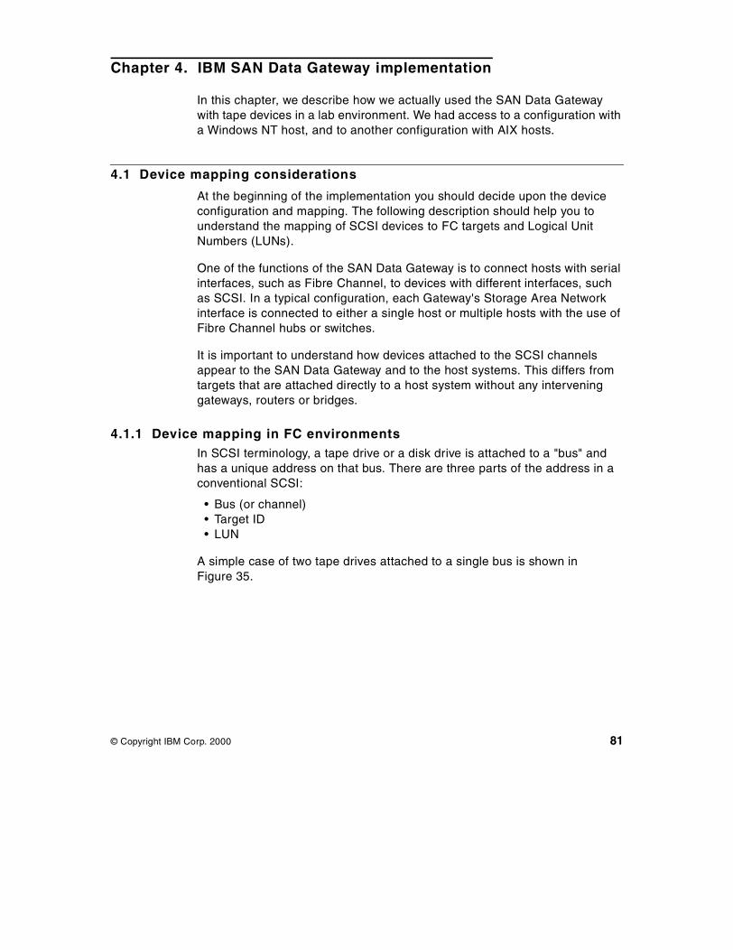
Chapter 4. IBM SAN Data Gateway implementation
In this chapter, we describe how we actually used the SAN Data Gatewaywith tape devices in a lab environment. We had access to a configuration witha Windows NT host, and to another configuration with AIX hosts.
4.1 Device mapping considerations
At the beginning of the implementation you should decide upon the deviceconfiguration and mapping. The following description should help you tounderstand the mapping of SCSI devices to FC targets and Logical UnitNumbers (LUNs).
One of the functions of the SAN Data Gateway is to connect hosts with serialinterfaces, such as Fibre Channel, to devices with different interfaces, suchas SCSI. In a typical configuration, each Gateway's Storage Area Networkinterface is connected to either a single host or multiple hosts with the use ofFibre Channel hubs or switches.
It is important to understand how devices attached to the SCSI channelsappear to the SAN Data Gateway and to the host systems. This differs fromtargets that are attached directly to a host system without any interveninggateways, routers or bridges.
4.1.1 Device mapping in FC environmentsIn SCSI terminology, a tape drive or a disk drive is attached to a "bus" andhas a unique address on that bus. There are three parts of the address in aconventional SCSI:
• Bus (or channel)• Target ID• LUN
A simple case of two tape drives attached to a single bus is shown inFigure 35.
© Copyright IBM Corp. 2000 81
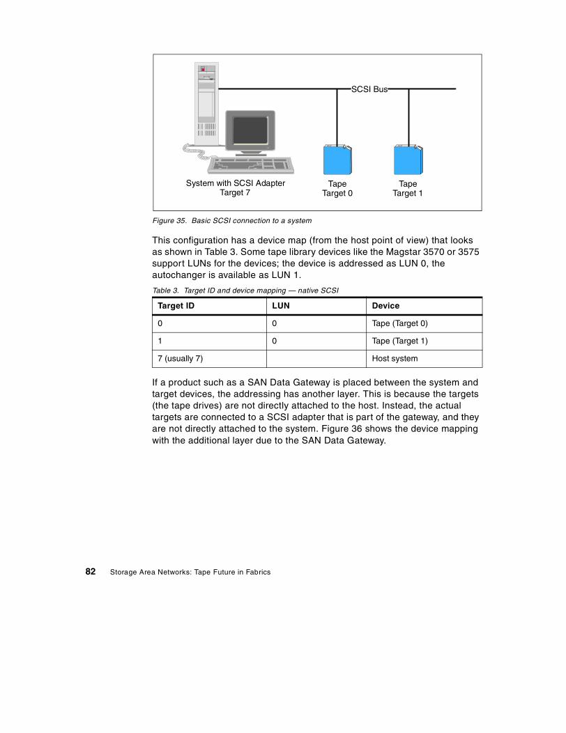
Figure 35. Basic SCSI connection to a system
This configuration has a device map (from the host point of view) that looksas shown in Table 3. Some tape library devices like the Magstar 3570 or 3575support LUNs for the devices; the device is addressed as LUN 0, theautochanger is available as LUN 1.
Table 3. Target ID and device mapping — native SCSI
If a product such as a SAN Data Gateway is placed between the system andtarget devices, the addressing has another layer. This is because the targets(the tape drives) are not directly attached to the host. Instead, the actualtargets are connected to a SCSI adapter that is part of the gateway, and theyare not directly attached to the system. Figure 36 shows the device mappingwith the additional layer due to the SAN Data Gateway.
Target ID LUN Device
0 0 Tape (Target 0)
1 0 Tape (Target 1)
7 (usually 7) Host system
TapeTarget 0
TapeTarget 1
System with SCSI AdapterTarget 7
SCSI Bus
82 Storage Area Networks: Tape Future in Fabrics

Figure 36. SAN Data Gateway attached through Fibre Channel — host view
The system now only has a single target ID (target 0 in this case) directlyattached to the SAN Data Gateway. The gateway forwards commands to andfrom its targets, the tape drives. However, there is a need to map the devices(tapes) so the host system can use them. This is achieved by using anotherlayer of mapping, LUNs. The device map might now look like Table 4 from thehost point of view.
Table 4. Device Map from the Host Point of View — with SAN Data Gateway
Note that LUN 0 points to the SAN Data Gateway. This allows you to sendcommands to control the gateway. This is referred to as the Command andControl Interface.
We simplified this by assuming hard IDs for the Fibre Channel devices. Ahard ID is a number from 0 to 127 used in place of the World-Wide Name(WWN) assigned to each Fibre Channel device. It requires that SCSI devicesare mapped exactly the same way every time the host is booted again. TheSAN Data Gateway has the ability to deal with these issues, because itpreserves the mapping of device addresses.
Target ID LUN Device
0 0 SAN Data Gateway
0 1 Tape 0
0 2 Tape 1
127 Host system
Tape 0Target 0LUN 1
Tape 1Target 0LUN 2
System with FC AdapterTarget 127
SCSI Bus
SAN GatewayTarget 0, LUN 0
IBM SAN Data Gateway implementation 83

When using Fibre Channel hubs or switches, hard IDs are preferred becausethe host won't lose track of the devices. Scrambled IDs are not a concernwhen the SAN Data Gateway is used in a Fibre Channel point-to-pointconfiguration.
4.1.2 Mapping devices to targets and LUNsThe host operating system imposes limitations on the number of LUNs andtarget IDs. The most common SCSI implementation in use (SCSI-2) allowseight LUNs per target ID, so if you want to connect more than seven devices(one LUN is reserved for the gateway), this address limitation needs to becircumvented. Fibre Channel and other serial interfaces implement a newerSCSI specification (SCSI-3), which allows for many more LUNs per target.
The number of LUNs is limited by the host operating system. In case ofSCSI-2 protocol, another abstraction is required from the host adapter. Thisvaries with the implementation, but a common method is to create additional"pseudo" target IDs when you use up the eight LUNs. When adding moredrives, the host system "sees" target 0 has LUNs 0 through 7, then target 1,LUNs 0 through 7 for the next eight devices, continuing until all devices areaccounted for. With a SCSI-2 type mapping, there are 16 target IDs availableper bus, but one must be reserved for the host adapter. That allows for 15targets with 8 LUNs each or 120 total devices.
Different operating systems have different limits on the number of LUNssupported. For example, Windows NT 4.0 had an eight LUN limit until therelease of Service Pack 4. The limit is now 255 LUNs per target ID. Theincrease implies that you need not use "pseudo" targets. When the newerSCSI-3 specifications are implemented by the operating system vendors, it ispossible to go beyond the SCSI-2 limits of device addressing. The SAN DataGateway fully supports SCSI-3 protocol for disk and tape.
Figure 37 explains the mapping of devices to targets and LUNs with anexample of a Tivoli Storage Manager for NT installation with IBM Magstar3570-C12 Tape Library and the SAN Data Gateway. In the upper part you seethe Service Point Terminal command output for fcShowDevs, and in thelower part you see the Tivoli Storage Manager command output for q drive.
84 Storage Area Networks: Tape Future in Fabrics
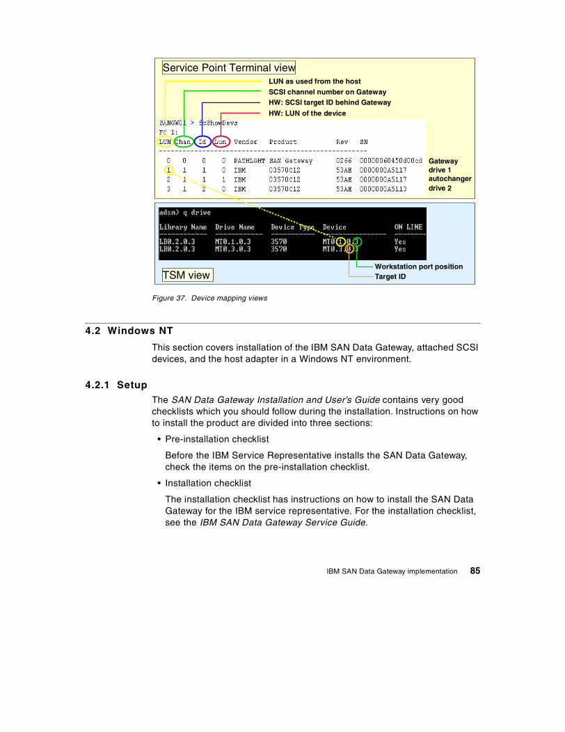
Figure 37. Device mapping views
4.2 Windows NT
This section covers installation of the IBM SAN Data Gateway, attached SCSIdevices, and the host adapter in a Windows NT environment.
4.2.1 SetupThe SAN Data Gateway Installation and User’s Guide contains very goodchecklists which you should follow during the installation. Instructions on howto install the product are divided into three sections:
• Pre-installation checklist
Before the IBM Service Representative installs the SAN Data Gateway,check the items on the pre-installation checklist.
• Installation checklist
The installation checklist has instructions on how to install the SAN DataGateway for the IBM service representative. For the installation checklist,see the IBM SAN Data Gateway Service Guide.
Workstation port positionTarget IDTSM view
drive 1autochangerdrive 2
Gateway
LUN as used from the hostSCSI channel number on Gateway
HW: LUN of the device
Service Point Terminal view
HW: SCSI target ID behind Gateway
IBM SAN Data Gateway implementation 85

• Post-installation checklist
After the IBM Service Representative installs the SAN Data Gateway, gothrough the post-installation checklist.
Test SetupFigure 38 shows the components and installation setup we used for the SANData Gateway installation.
Figure 38. Installation setup
Pre-installation tasks1. Inform the IBM service representative whether the gateway should be
desk top or rack mount installed.
2. Check the Operating System requirements. For Windows NT it is Version4.0, Service Pack 4 or later, plus required hotfixes. Those hotfixes and acurrent list of supported platforms, as well as device driver and firmwarerequirements, are mentioned on the Web site:
http://www.ibm.com/storage/SANGateway/
Windows NTADSM for NTSAN Data Gateway SpecialistHBA
SAN Data Gateway
Magstar MP 3570-C12Tape Library
Drive 1 Drive 2
FC 2FC 1
SCSI 1
Ethernet Hub
HBA
86 Storage Area Networks: Tape Future in Fabrics

You can check the level of the OS at boot time, for example, up to theService Pack level.
3. Install the FC Host Bus Adapter, for Windows NT this is the QLogic cardQLA2100.
During the installation you have to update the QLogic card BIOS, althoughthe readme file of the QLogic installation files does not state this clearly:
1. Copy the files from the CD-ROM x:\NT\2100 directory to a floppydiskette from which you can boot. If you downloaded a later version ofthe driver package, extract that to the floppy instead.
2. Shut down the system.
3. Install the HBA in an appropriate 32 or 64 bit PCI slot.
4. Boot the system with the floppy diskette from which you can boot.
5. From the DOS prompt, enter the command: ql2xutil /L /F
6. When the procedure completes, remove the floppy.
7. Boot Windows NT.
8. Extract the file you downloaded (if necessary) to a local, temporarydirectory, but only if you have downloaded updated device drivers.
9. From the Windows Start menu, select Settings, Control Panel, thenopen the SCSI Adapters applet.
10.Click on the Drivers tab. If the driver is already present for theQLA2100, click on it, then press the Remove button.
11.Click on the Add button.
12.Click on the Have Disk button. If you have downloaded updateddrivers, provide the path to the temporary directory where they arelocated. If you use the CD-ROM, the drivers are located in the directoryx:\NT\ 2100, where x is the letter for the CD-ROM drive.
13.Confirm the path and wait for the driver to install.
14.When you are prompted to reboot the system, select “Yes“.
Verify that the device driver has started. It should show "started" withouthaving any FC cable, gateway, or devices installed yet. You may see asecond device entry for the QLogic card stating a Pseudo device. This iscorrect, and it is there for hotplugging purposes.
4. Check that all host FC cables are either ordered or already installed andmark them with a host server identifier and the SAN Data Gatewayidentifier.
IBM SAN Data Gateway implementation 87

5. Ensure that the tape system installation has been completed. Install thenewest device driver. Mark both ends of each SCSI cable with
• Target ID and channel number• SAN Data Gateway ID and channel number.
6. Decide the SAN Data Gateway Ethernet port configuration parameters:
• Static IP address• Netmask (if required)• SAN Data Gateway name (optional, default name is Gateway)
If the gateway is not on the same TCP/IP subnet as the StorWatch SANData Gateway Specialist, assign the default network gateway addressand/or route table entries.
7. Run the Ethernet cable from the NT server with the StorWatch SAN DataGateway Specialist to the Ethernet network hub.
8. Run the Ethernet cable from the network hub to where the SAN DataGateway will be installed. Leave it unconnected for the IBM servicerepresentative to install.
Installation tasksThe IBM service representative handles the installation of the SAN DataGateway according to the installation checklist in the Service Guide. They willask you afterwards to verify that all target devices are available to the hostsystems.
Post-installation tasks1. Install the StorWatch SAN Data Gateway Specialist software. For the
latest version, see the Web site:
http://www.ibm.com/storage/SANGateway/
2. Ensure that the StorWatch SAN Data Gateway Specialist has access tothe same Ethernet subnet as the SAN Data Gateway.
3. Start-up the StorWatch SAN Data Gateway Specialist Server.
4. Start-up the StorWatch SAN Data Gateway Specialist Client.
• Connect to the Specialist Server using its name or IP address (if it doesnot find the Server running on the same system).
• Log on and add a new administrator account and password. This newadministrator account will automatically deactivate the default StorWatchaccount which makes sense because of security reasons.
• Log off and log on using the new administrator.
88 Storage Area Networks: Tape Future in Fabrics

5. From the Client, connect to the desired SAN Data Gateway (use ConnectSAN Data Gateway from the tools menu group and enter the SAN DataGateway name or IP address) or discover all installed gateways withfunction Discover Net.
Figure 39 shows the Specialist after connecting the SAN Data Gateway.The bar at the bottom shows the actual status of the discover net function.
Figure 39. SAN Data Gateway in the StorWatch SAN Data Gateway Specialist
6. Save your user / administrator setup with Save Setup as... from the filemenu group. This function saves the currently viewed selection ofgateways, not the configuration itself.
7. If later firmware for the gateway is available, update each gateway withfunction Update Firmware and Restart Gateway from the Control menugroup.
Figure 40 shows the Update Firmware and Restart Gateway functions inthe Controls menu group. Figure 41 shows a warning message that comesup after Restart Gateway, since the restart function re-boots the currentlyselected gateway. This immediately stops all I/O activity.
IBM SAN Data Gateway implementation 89

Figure 40. SAN Data Gateway Specialist — update firmware and restart
Figure 41. Restart warning message
8. If you have more than one host connected to the SAN Data Gateway, youmay need to enable Access Control. Use function Access Control in thecontrol menu group to place check marks in the matrix to allow accessbetween the FC connections and the SCSI channels. All combinations arepossible.
9. At this time you MUST save your SAN Data Gateway configuration with thefunction Save SAN Data Gateway Configuration in the tools menugroup.
10.Become familiar with using the StorWatch SAN Data Gateway Specialist.
11.Use the StorWatch Specialist to monitor and maintain your SAN. Thereare functions available like event logging, health check, and heartbeatnotification.
Save your SAN Data Gateway configuration periodically. You must save yourconfiguration if you make changes to access control or operating parametersettings.
90 Storage Area Networks: Tape Future in Fabrics
4.2.2 Host considerationsThe connection of devices in a SAN changes the way they are seen in theOperating System. This is achieved by using another layer of mapping. Thedevice map has been added to reflect devices in the host which havepreviously been attached to multiple SCSI cards and are now attached to asingle FC HBA.
The address mapping is described in 4.1, “Device mapping considerations”on page 81. Here we want to show how Windows NT defines the devices asshown in Figure 42, and how the StorWatch SAN Data Gateway defines thedevice shown in Figure 43 on page 92.
Figure 42. Windows NT SCSI device settings
IBM SAN Data Gateway implementation 91

Figure 43. StorWatch SAN Data Gateway — device view
4.3 AIX
We describe here our lab setup and experiences using the SAN DataGateway with AIX.
4.3.1 SetupThe basic steps that you will need to perform to install the IBM SAN DataGateway for use under AIX are outlined here:
1. Install the FC Adapter driver on AIX; it is called fchan0. Use smitty toupdate the FCP operation parameter to Yes.
2. Install the FC Adapter card on your RS/6000.
3. Update the FC Adapter card BIOS (or check your BIOS is up-to-date).
4. Connect your SCSI devices to the selected SCSI Port(s) of the SAN DataGateway.
5. Connect the Fibre Channel cable from the host FC Adapter to the selectedSAN Data Gateway fibre port.
92 Storage Area Networks: Tape Future in Fabrics
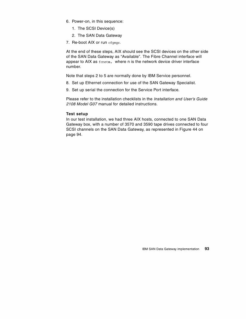
6. Power-on, in this sequence:
1. The SCSI Device(s)
2. The SAN Data Gateway
7. Re-boot AIX or run cfgmgr.
At the end of these steps, AIX should see the SCSI devices on the other sideof the SAN Data Gateway as “Available”. The Fibre Channel interface willappear to AIX as fcnetn, where n is the network device driver interfacenumber.
Note that steps 2 to 5 are normally done by IBM Service personnel.
8. Set up Ethernet connection for use of the SAN Gateway Specialist.
9. Set up serial the connection for the Service Port interface.
Please refer to the installation checklists in the Installation and User’s Guide2108 Model G07 manual for detailed instructions.
Test setupIn our test installation, we had three AIX hosts, connected to one SAN DataGateway box, with a number of 3570 and 3590 tape drives connected to fourSCSI channels on the SAN Data Gateway, as represented in Figure 44 onpage 94.
IBM SAN Data Gateway implementation 93

Figure 44. AIX SAN lab configuration
The tape device driver is Atape at the latest level, which include the supportfor Fibre Channel attached tape drives.
The Access Control were defined so that the ost32 host, connected FC port1, had access to SCSI ports 3 and 4, while the ost28 host on FC port 2, hadaccess to SCSI channel 1, and the gunslinger host had access to SCSIchannel 2. That is, we did SCSI Port zoning so that no devices were seen bytwo hosts.
SCSI channels
Fibre Channel <500m.
3570C12
3570C12
3590E11
3590B11
43
113590B11
1210
13
21
9
8
1
03570C1A
3570C1A
SCSI
1FC
SAN DataGateway
32
Gunslinger OST32OST28
3570B11
94 Storage Area Networks: Tape Future in Fabrics

The Service Port command fcShowDevs thus gives the output shown inFigure 45.
Figure 45. AIX lab fcShowDevs output
The columns shown by fcShowDevs are:
LUN: the SCSI LUN of each target device. This LUN number is internalto the SAN Data Gateway, which is itself LUN 0 in this scheme.
Chan: the channel number of the SCSI interface
Id: the (hardware) target SCSI ID of each device.
Lun: the LUN number of the SCSI device.
The other columns are self-explanatory.
Some things are worth noticing here:
• The LUN numbers are just sequential numbers assigned by the SAN DataGateway to every device, whereas the Lun (notice the capitalization subtledistinction) is the SCSI LUN used by a given, real device. For example,the 3590B11 device has two LUNs: LUN 0 is the drive, LUN 1 is the MediaChanger. This is fixed for this type of device, and cannot be changed.
• The SCSI ID for devices are the ones defined in the device; this isnormally selected at installation time.
266.7 > fcShowDevsFC 1:LUN Chan Id Lun Vendor Product Rev SN-----------------------------------------------------
0 0 0 0 PATHLGHT SAN Gateway 0266 00000060450d00fa34 3 11 0 IBM 03590B11 B639 00000003919135 3 11 1 IBM 03590B11 B639 00000003919136 4 0 0 IBM 03570C1A 5324 00000000034437 4 0 1 IBM 03575L18 2.17 038 4 1 0 IBM 03570C1A 5324 00000000034640 4 12 0 IBM 03590E11 C523 0000000E009541 4 12 1 IBM 03590E11 C523 0000000E0095
FC 2:LUN Chan Id Lun Vendor Product Rev SN-----------------------------------------------------
0 0 0 0 PATHLGHT SAN Gateway 0266 00000060450d00fa26 1 8 0 IBM 03570C12 53AE 00000000402727 1 8 1 IBM 03570C12 53AE 00000000402728 1 10 0 IBM 03590E11 C502 0000000E008629 1 10 1 IBM 03590E11 C502 0000000E008632 1 9 0 IBM 03570C12 53AE 00000131098333 1 9 1 IBM 03570C12 53AE 000001310983
FC 3:LUN Chan Id Lun Vendor Product Rev SN-----------------------------------------------------
0 0 0 0 PATHLGHT SAN Gateway 0266 00000060450d00fa16 2 13 0 IBM 03590B11 B639 00012345678917 2 13 1 IBM 03590B11 B639 000123456789
value = 64 = 0x40 = '@'
IBM SAN Data Gateway implementation 95

Seen from one of the hosts, in this example by ost28, which happens to beconnected on FC 2, the SMITTY panel displaying tape devices is shown inFigure 46.
Figure 46. AIX lab as seen from ost28
Some notes regarding Figure 46:
• rmt0 and rmt2 are directly-attached 8mm drives.
• The devices attached to the SAN Data Gateway have an (FCP) indication,meaning Fibre Channel Protocol, which is added by the AIX Atape DeviceDriver.
• The addresses of the FC-attached devices have the same SCSI IDs andLUNs as seen from the SAN Data Gateway. This is done again by theAtape device driver, which gets this information from the gateway, andputs it in the location field used by lsdev, as a convenience. If we were notusing Atape, but the standard AIX ost (other SCSI tape) driver, we wouldbe in a situation similar to the Windows NT lab, and see all tape driveswith the same SCSI ID of 0, and the LUN number as returned by the SANData Gateway. This also means that two hosts having access to the samephysical device would see it with different SCSI IDs, as these are actuallythe LUNs returned by the SAN Data Gateway.
• The parent adapter for the FCP devices is called a fchan0 device.
Note: The AIX location code format for SCSI tape devices has a structure ofAA-BB-CC-S,L where:
• AA: A value of 00 for the AA field indicates the controlling adapter cardis located in the CPU drawer or system unit, depending on the type ofsystem.
• BB: The BB field identifies the I/O bus and slot containing the card. Thefirst digit identifies the I/O bus. It is 0 for the standard I/O bus and 1 forthe optional I/O bus. The second digit is the slot on the indicated I/Obus containing the card. A value of 00 for the BB field indicates thestandard SCSI controller.
Command: OK stdout: yes stderr: no
Before command completion, additional instructions may appear below.
rmt0 Available 20-60-00-2,0 5.0 GB 8mm Tape Drivermt1 Available 10-60-01-8,0 IBM Magstar MP Tape Subsystem (FCP)rmt2 Available 40-60-00-6,0 Differential SCSI 8mm Tape Drivermt4 Available 10-60-01-10,0 IBM 3590 Tape Drive and Medium Changer (FCP)rmt6 Available 10-60-01-9,0 IBM Magstar MP Tape Subsystem (FCP)
96 Storage Area Networks: Tape Future in Fabrics

• CC: The CC field identifies the card’s SCSI bus that the device isattached to. For a card that provides only a single SCSI bus, this fieldwill be set to 00. Otherwise, a value of 00 indicates a device attachedto the card’s internal SCSI bus, and a value of 01 indicates a deviceattached to the card’s external SCSI bus.
• S,L: The S,L field identifies the SCSI ID and logical unit number (LUN)of the SCSI device. The S value indicates the SCSI ID and the L valueindicates the LUN.
For example, the entry labelled IBM Magstar MP Tape Subsystem (FCP) onFigure 46 on page 96 means:
• 10-60 is the Adapter location, identifying the drawer and the I/O busand slot of the FIbre Channel adapter in the RS/6000.
• 01 says that this is an External bus
• 8,0 means SCSI ID 8 and LUN 0 for this device.
4.3.2 Host considerationsConnecting devices across a SAN completely changes the way devices areconfigured and managed on a host system.
If you don’t have a SAN, but normal direct SCSI connections instead, thedevices are generally dedicated to one machine, and all the I/O devicesconnected belong to that host.
In a SAN, a host system will see all the devices connected to its FC Adapter,which appears to the host as one SCSI bus; this can include devicesbelonging to other hosts.
For example, under AIX, a cfgmgr will detect all the devices on all its SCSIbusses, and attempt to configure them. And as cfgmgr also runs at boot time,there is no way to prevent AIX from doing that.
In a SAN environment, if nothing is done to control this situation, this couldlead to:
• Devices belonging to one host being accessed by other hosts, withpotentially destructive consequences.
• Devices that were once viewed in a given sequence having that sequencechanged just because a new device was added somewhere on the SAN.
• Devices can be known under one name and address from one system,and have another name when viewed from another system, thus leading toconfusion and prompting operational errors.
IBM SAN Data Gateway implementation 97
Clearly, this has to be avoided.
There are two aspects to solve to avoid these problems:
• Addressing• Access control
The SAN Data Gateway addresses these two aspects by:
• Persistent address mapping: The SAN Data Gateway maintains a table ofthe devices LUNs, so that the hosts always see a given device with thesame SCSI address triplet. If a new device is added, it will be assigned anew, unique, LUN. And if a device is removed, its LUN is reserved just incase you reconnect it, and also to avoid that a new device gets the sameLUN number.
• Access control (also called zoning): This function of the SAN DataGateway allows you to assign a SCSI channel to a given FC channel, thatis, host. The devices on this SCSI channels are then invisible from theother hosts, thus protecting you from potentially destructive multiple hostaccess. Even though you could let all the hosts see all the SCSI channels,in a normal production mode, you would have only one host accessing aSCSI bus.
This mode of operation is referred to as port zoning, because you applyrestrictions (or authorizations) at the SCSI port, that is, SCSI bus, level.This means that if you have, for example, two tape drives on a SCSI bus,you cannot assign one drive to one host and the other to another hostusing port zoning.
There is another type of zoning, called LUN zoning, where the accesscontrols can be applied at the LUN level. This would allow you to have twohosts accessing one drive each on the SCSI bus with two tape drives, forexample.
The SAN Data Gateway does not presently offer LUN zoning, even thoughthe Pathlight Web site mentions that the SAN Data Gateway can do it.
4.4 StorWatch SAN Data Gateway Specialist
This section contains an overview about the functions of the StorWatch SANData Gateway Specialist. The Specialist runs on Windows NT, independent ofthe server platform, to which the gateway is attached.
98 Storage Area Networks: Tape Future in Fabrics

The StorWatch SAN Data Gateway Specialist is the recommended interfaceto configure and maintain the gateway remotely on a Windows NT server. TheSpecialist is outband connected to the gateway through an Ethernetconnection with TCP/IP protocol. The SW is delivered as CD with thegateway. You can either install it from the CD or download it from the followingWeb site:
http://www.ibm.com/storage/SANGateway/
In any case, we suggest checking the Web site for the newest version. Theinstallation steps are described in 4.2.1, “Setup” on page 85 underpost-installation tasks. In this section we want to describe the differentfunctions of the Specialist software.
Before a Client can manage any SAN gateways, it must connect to the Servercomponent. If the Server and Client are running on the same system, aconnection is automatically started when the Client starts. Otherwise, whenthe application starts, it will show the connection to the server box and youhave to enter the name or IP address. After you connect to the server, log on.
At this point, you can:
• Retrieve a saved setup.
• Perform a "Discovery" of all gateways on a subnet.
• Connect directly to a gateway.
Menus allow the user to view the SAN Data Gateways and the devicesconnected on them, and perform various actions. From the main screen, sixmajor menu groups are available:
• File• View• Admin• Tools• Controls• Help
4.4.1 File menu groupThe File menu group has commands to load, manipulate, and save setupfiles. A setup file is your selection of gateways, you want to see in theSpecialist. You can also say it is a view. It does not relate to the actualconfiguration parameters, which you can (and should) save with a differentfunction.
IBM SAN Data Gateway implementation 99

4.4.2 View menu groupThe view can show either the entire collection of gateways making up thesetup viewed in a hierarchical tree, or it can show the front panel of a singlegateway when checking this option. See Figure 47.
Figure 47. SAN Data Gateway front panel
This view of the panel can be useful to get a quick status of the gateway.
The Refresh SAN Data Gateway Data option forces the Server to contactthe currently selected gateway and update all the data. It does not restart thegateway. This option is available in the Controls menu group to re-boot thegateway with the current parameters.
4.4.3 Admin menu groupThe Admin (administrative) menu group offers control of connecting to theserver, logging on and user and password control. Please note that theaddition of new users requires administrator privileges.
100 Storage Area Networks: Tape Future in Fabrics

4.4.4 Tools menu groupThe Tools menu group offers options that allow locating and connecting togateway, and control the reporting of a gateway status.
Figure 48. Tools menu group
With the Discover Net option in Figure 48 you can discover all gateways in aparticular subnet. This option needs some time. An alternative is the ConnectSAN Data Gateway option that connects to a specific single gateway, whichyou identify by name or IP address.
The Health Check submenus allow you to determine the status of theselected gateway. You can also test target devices and controllers. SeeFigure 49 for selecting Health Check Intervals and Levels. The Health Checkfunction posts SNMP traps to send status information to managementapplications. The gateway broadcasts SNMP traps on the local IP networksegment.
Figure 49. Health check submenu
IBM SAN Data Gateway implementation 101

The Events submenu allows you to control how event logs are displayed andhow traps are generated.
The Save SAN Data Gateway Configuration function copies the vitalconfiguration information from the selected SAN Data Gateway to a file. It isimportant to preserve the mapping of device addresses. The SAN DataGateway automatically saves the device map in nonvolatile storage to ensurethe persistence between boots and power cycles. To provide a backup of thedevice maps and other configured parameters, you must save aconfiguration when you:
• Install the SAN Data Gateway• Add new devices• Remove devices permanently• Change Target IDs or LUNs
A configuration, for example, can be reloaded when an IBM ServiceRepresentative has to replace the gateway. Save and back up your SAN DataGateway configurations frequently.
Please note that the function Save Setup fulfills a different purpose. TheStorWatch SAN Data Gateway Specialist is able to work with multiplegateways which have been previously detected by Discover Net. Save Setupsaves the currently viewed collection of gateways, so it only saves a view, notthe configuration.
The Load SAN Data Gateway Configuration function restores a previouslysaved configuration if you need to replace a gateway. After the load of aconfiguration, you also have to restart the SAN Data Gateway. A restart willre-boot the selected gateway. This immediately stops all I/O activity.
4.4.5 Controls menu groupThe Controls menu group of options allows you to control how the currentlyselected gateway performs. This includes the definition of the Access Control,the setting of several parameters for SCSI channel, Fibre Channel and targetdevice, and also the Update Firmware and Restart Gateway function.
The Access Control function implements the zoning of the SANconfiguration based on SCSI and FC ports. This prevents accessing the sametarget device from more than one host. All combinations are possible.
102 Storage Area Networks: Tape Future in Fabrics

Figure 50 shows an example where FC 1 has access to SCSI channels 2, 3,and 4, and FC 2 has access to SCSI channels 1 and 4. This means that thedevices on SCSI channel 4 can be accessed by multiple hosts, which shouldbe used carefully.
Figure 50. Set access control function
After saving the settings you will get the message shown in Figure 51. TheRestart Gateway function is also provided in the Control menu group and willimmediately stop all I/O activity. Any connected host must stop sendingcommands to devices attached to the gateway or it will cause time-outs orother failures to be reported on the host system. To reflect the changes in thedialog, you have to refresh the selected SAN Data Gateway.
Figure 51. Warning message after setting new access control
IBM SAN Data Gateway implementation 103

The Update Firmware function provides you with a list of firmware files fromwhich you can choose. Select a file and press the download button. Theselected firmware file is sent to the currently selected device (gateway ortarget device). You must stop all activity from the connected hosts before youupdate the firmware for the gateway. After you update the firmware for thegateway, you must re-boot to load the new software.
The Identify SAN Data Gateway allows you to visually identify the selectedGateway by a Ready light that flashes rapidly.
4.5 The Service Port interface
The Service Port Interface of the SAN Data Gateway is an RS-232 connectionand is used to perform local service and diagnostics. It is primarily intendedfor IBM Service personnel, but can also be of use if you don’t have access tothe SAN Gateway Specialist product.
The connection to the Service Port can be used from a TTY device, or byusing a terminal emulator on an NT or AIX system.
Once you are connected to the Service Port, you are in a basic shell interfacesimilar to a UNIX shell, which lets you enter Service Port commands. You canalso use the vi line editing commands. All these commands are referencedalphabetically in the User’s Guide 2108 Model G07 manual, Appendix B.
The manual lists all the Service Port commands in alphabetical order. Wefound it difficult at first to select which command to use for a given function,so we are trying to help you by listing these commands grouped by category,and by telling you which commands to use for the main tasks you will have toaccomplish.
104 Storage Area Networks: Tape Future in Fabrics

Commands grouped by categoryThe following commands are grouped by category:
• File Management commands:
Use these commands to manipulate files in the SAN Data Gateway:
• cd: change directory
• ls or ll: list the files in the SAN Data Gateway flash memory
• rm: remove a file
• Connectivity and Control commands
This set of commands is used for Access Control, to define which host isseeing which SCSI Channel.
• setFcChanMask: specify which FC channel is allowed to access whichSCSI channel
• setFcFrameSize: change the frame size used on a FC channel. Younormally don’t have to change this (default is 2048 bytes)
• setFcHardID: set the Hard AL_PA (Arbitrated Loop PermanentAddress) ID for a Fibre Channel, or work with Soft ID method byspecifying 255.
• setFcSplit: assign SCSI channels 1 and 3 for exclusive use by the FCinterface 1. SCSI channels 2 and 4 for exclusive use by FC interface 2.This is predefined, simple way to set Access control on the SAN DataGateway. If you need other assignments, use the setFcChanMaskcommand.
• setFcNormal: remove the assignments defined with the setFcSplitcommand.
• disableCC: make the SAN Data Gateway LUN not available to receiveSCSI commands and controls.
• enableCC: enable the SAN Data Gateway LUN for SCSI commandsand controls.
• Device Management commands:
Use these commands to manipulate the Persistent Address Mapping tablein the SAN Data Gateway:
• mapShowDatabase: show the persistent address mapping table,including all devices, those presently connected as well as the oneswhich may have been previously connected.
IBM SAN Data Gateway implementation 105

• mapRebuildDatabase: erase the Persistent Address Map database. Areboot command is then needed to reconstruct a new database in theSAN Data Gateway.
• mapWinnowDatabase: eliminate inactive device entries from thePersistent Address Map database.
• mapShowDevs: show a cross reference map of device addresses,ordered by Device ID.
• scsiRescan: do a SCSI scan on one or all SCSI channels. Use if youadd a new SCSI device, or if you have to replace a SCSI device. Therescan will update the configuration data in the gateway; thereplacement device will have the same LUN as the old one.
• scsiShow: list all SCSI channels and all the attached SCSI devices.ID/LUN.
• targets: lists each target device attached to the gateway, withdescriptions as returned by SCSI Inquiry.
• fcShowDevs: lists all attached target devices with both their SCSIaddresses and the Fibre Channel LUN assigned to them.
• Ethernet commands:
Use these commands to manage Ethernet access to the SAN DataGateway using the SAN Gateway Specialist. Please refer to the manualfor details:
• ethAddrSet• ethEnable• ethAddrGet• gateAddrSet• gateAddrGet• ethDisable• ethEnable• host• hostNameSet• route• trapDestAdd, trapDestRemove, trapDestShow• userAdd• userList• userDelete• ping
106 Storage Area Networks: Tape Future in Fabrics

• Healthcheck commands:
Use these commands to control the Health checking behavior, like level ofchecking and interval. The Health Check function broadcasts SNMP trapson the local UP network segment, and also sends them to the SANGateway Specialist server. You can specify additional recipient hosts forSNMP events by the trapDestAdd command:
• hlthChkintervalSet• hlthChkLevelGet• hlthChkLevelSet• hlthChkNow
• Diagnostic and Control commands:
These commands are normally used by service personnel. The showBoxcommand gives you a graphical view of the SAN Data Gateway box:
• reboot• reset• showBox• snaVersion• sysVpdShow• loggerDumpCurrent• loggerDump• ifShow• fcShow• csEtimeShow• ridTag• initializeBox
• OnBoard diagnostic commands:
These are additional commands, for use by trained service personnel only,which are not documented in the manual.
IBM SAN Data Gateway implementation 107

Task-oriented approachTasks and their associated commands are listed in Table 5.
Table 5. Tasks and associated commands
Task Command Remarks
Set Gateway name hostNameSet Default is Gateway, pick aname according to yourstandards
Define a new administrator userAdd Default is StorWatch,change it for securityreasons
Set Gateway Ethernetaddress and submask
ethAddrSet See your networkadministrator
Check Ethernetconnectivity
ping
Display picture of thegateway
showBox
List target SCSI devices targets
List all SCSI channels andthe attached SCSI devices
scsiShow
List all target devices withboth SCSI IDs and FC LUN
fcShowDevs
Rescan all SCSI channels scsiRescan Use this after installingnew devices
Show a cross-reference ofdevice addresses byDevice ID
mapShowDevs
Display Persistent AddressMapping table
mapShowDatabase To get SCSI mappings
Define Access Controlrestrictions
setFcChanMask Define which host can seewhich SCSI port
108 Storage Area Networks: Tape Future in Fabrics

Chapter 5. Scenarios and sample configurations
In this chapter, we present selected sample configurations, using thetechnologies and functions we have introduced in the previous sections. Thesamples are selected with a specific customer benefit in mind, likeovercoming distance limitations, improving availability, and enhancingconnectivity.
5.1 Distance solution
Reasons for using distance solutions could be tape vaulting, centralization ofthe tape pool, or layout flexibility in the machine room.
The SAN Data Gateway solves problems like the 25 m cable length restrictionof SCSI. You can have distances between the gateway and the FC-ALadapter of up to 500 m with multi-mode fiber cables. The attaching fiber cablemust be 50.0/125 micrometers for distances of up to 500 meters, or 62.5/125micrometers for distances up to 175 meters.
For longer distances up to 11 kilometers, you can choose the IBM FibreChannel Hub. You need two hubs which are connected by the longwave GBICports to get the long distance. A short-wave connection of up to 500 m isused between hub and the SAN Data Gateway and the hub to the host.
The IBM Fibre Channel Switch together with the IBM SAN Data GatewayRouter are further possibilities to avoid the 25 m cable restriction for SCSIattached devices. The switch supports both shortwave as well as longwaveoptical connections.
Figure 52 shows an example for an attachment of two Magstar MP 3570 tapelibraries through a gateway to a remote Windows NT system. The FCattachment in this case will give you 500 m of distance. To go even further,you need a hub, which provides an additional 10 km of distance.
© Copyright IBM Corp. 2000 109

Figure 52. Distance solution with SAN Data Gateway
5.2 Connectivity solution
Connectivity has different aspects. Configurations can get quite complicatedwhen you want to connect multiple hosts to a number of drives. Sometimes itis simply a cabling problem, especially when you want to switch devicesbetween different hosts for example for fail-over purposes. Magstar 3590helps in this area, since it has two SCSI connectors with which it can beconnected to two hosts. Most tape drives only have one SCSI connector perdrive.
• Multiple devices attached to a single (or few) hosts
The advantage of SAN in this configuration is that it reduces the number ofhost adapters you need to attach the devices.
The SAN Data Gateway currently supports 4 SCSI channels with 3 FC-ALadapters. The number of drives to attach to them is more or less restrictedby the effective gateway throughput of around 110 MB/sec.
The use of hubs in SAN configurations increases the device connectivityeven more, but hubs have some issues with multiple hosts on the FC-ALloop such as LIP and arbitration.
You can also use the Fibre Channel Switch with the SAN Data GatewayRouter or a hub for device fan-out, but each router only supports 2 SCSIchannels, so the multiplication effect of the router is limited.
Windows NTServer
FChost
adapter
SA
ND
ata
Gat
eway
FibreChannel
UltraSCSI
3570
3570
500 m
25 m
110 Storage Area Networks: Tape Future in Fabrics

• Multiple hosts attached to a few devices or libraries
This sequential device sharing can be required with fail-overconfigurations where you want to connect a second host to the same tapelibrary, so you can switch to the second host without recabling. Otherexamples are test machines and application with direct client access totape.
The gateway currently supports up to 3 FC-AL ports, which meansattachment to three hosts. With either 2 or 3 FC-AL ports, the gatewaydoesn’t really help for host fan-out.
The IBM Fibre Channel Storage Hub may be a solution for host fan-out,since it has 7 ports, but the issues with multiple hosts on the FC-AL mayrestrict this possibility.
The use of the IBM Fibre Channel Switch with either 8 or 16 portsincreases the host fan-out which means the number of host connections ofSAN configurations. You also can cascade multiple switches to get aneven higher number of host connections.
Figure 53 shows a Magstar MP 3575 shared between two hosts. Theconnection of multiple hosts to a single drive in the 3575 is not possiblewithout a SAN solution, because each drive only has one SCSI connector.The access control function ensures that each host sees only its devices.Access control can be implemented with the SAN Data Gateway Specialistand is also called zoning. See 3.4.3, “Zoning or access control” on page 65for an explanation of the access control function.
Figure 53. Magstar MP 3575 shared between two hosts
Windows NTServer
FC hostadapter
SA
ND
ata
Gat
ew
ay
FC hostadapter
Windows NTServer
Accesscontrol
3575
3575 in Split Mode
UltraSCSI
FibreChannel
Scenarios and sample configurations 111
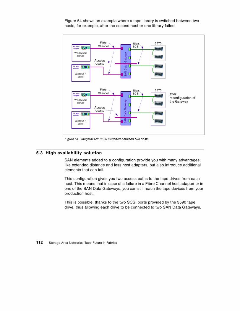
Figure 54 shows an example where a tape library is switched between twohosts, for example, after the second host or one library failed.
Figure 54. Magstar MP 3570 switched between two hosts
5.3 High availability solution
SAN elements added to a configuration provide you with many advantages,like extended distance and less host adapters, but also introduce additionalelements that can fail.
This configuration gives you two access paths to the tape drives from eachhost. This means that in case of a failure in a Fibre Channel host adapter or inone of the SAN Data Gateways, you can still reach the tape devices from yourproduction host.
This is possible, thanks to the two SCSI ports provided by the 3590 tapedrive, thus allowing each drive to be connected to two SAN Data Gateways.
Windows NTServer
FC hostadapter
SA
ND
ata
Gat
eway
FC hostadapter
Windows NTServer
Accesscontrol
3570FibreChannel
UltraSCSI
Windows NTServer
FC hostadapter
SA
ND
ata
Gat
eway
FC hostadapter
Windows NTServer
Accesscontrol
3570FibreChannel
UltraSCSI after
reconfiguration ofthe Gateway
112 Storage Area Networks: Tape Future in Fabrics

5.3.1 High availability for SAN componentsLet us take a simple case where you have only one host system, andconfigure your SAN boxes without any single point-of-failure in the SAN, asillustrated in Figure 55.
Figure 55. Avoiding single point-of-failure SAN elements
In normal operations, you would have the tape devices visible on both paths,but one given drive would be defined on one path only to the application. InTivoli Storage Manager terms, for example, you would have one Librarydefinition for each real tape library, and you would define the library driveswith the device address corresponding to one of the paths, the “production”path. In case of failure of the production path, you would basically tell TivoliStorage Manager to use the other path by updating the drives definitions tochange the device address to the address going over the other path.
If you do not have two SCSI ports per tape device, that is, any other tapedrive, you could have something equivalent using Fibre Channel Switchesand the Gateway Router instead of the SAN Data Gateway. See Figure 56.
Magstar
Windows NTServer
FC hostadapter
FC hostadapter
SA
ND
ata
Gat
eway
SA
ND
ata
Gat
eway
FibreChannel
MagstarLibrary
Magstarin Silo
UltraSCSI
Scenarios and sample configurations 113
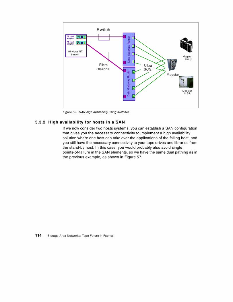
Figure 56. SAN high availability using switches
5.3.2 High availability for hosts in a SANIf we now consider two hosts systems, you can establish a SAN configurationthat gives you the necessary connectivity to implement a high availabilitysolution where one host can take over the applications of the failing host, andyou still have the necessary connectivity to your tape drives and libraries fromthe stand-by host. In this case, you would probably also avoid singlepoints-of-failure in the SAN elements, so we have the same dual pathing as inthe previous example, as shown in Figure 57.
Magstar
Windows NTServer
FC hostadapter
FC hostadapter
Dat
aG
atew
ayR
oute
rD
ata
Gat
ew
ayR
oute
r
FibreChannel
MagstarLibrary
Magstarin Silo
UltraSCSI
Switch
114 Storage Area Networks: Tape Future in Fabrics

Figure 57. SAN configuration without single points-of-failure
In the case of two hosts, you would have all the tape devices visible from bothhosts, but would probably not start the tape application on the stand-by host.
In case of failure of the production host, the operational tasks you would haveto perform are:
• Make the tape devices online on the stand-by host
• Bring up the application on the stand-by host
Note that this addresses only the tape connectivity issues. For applicationtake-over, you also need access from the stand-by host, to the disk drivesused by the application on the production system. For example, in the case ofTivoli Storage Manager, you would need access to at least the database andrecovery log volumes, and preferably also the disk storage pool volumes.This disk connectivity from the two hosts can be achieved either by havingthe disk devices connected on the SAN, for example, by using an additionalSAN Data Gateway, or by another type of multihost connection from the diskunits, like SSA disks connected to both hosts.
You could also implement this high availability solution using a SAN DataGateway Router and a Fibre Channel Switch, as illustrated in Figure 58.
Magstar
Windows NTServer
FC hostadapter
FC hostadapter
Windows NTServer
FC hostadapter
FC hostadapter
SA
ND
ata
Gat
eway
SA
ND
ata
Gat
eway
FibreChannel
MagstarLibrary
Magstarin Silo
UltraSCSI
Scenarios and sample configurations 115

Figure 58. High availability using a Fibre Channel Switch
5.4 Disaster recovery solution
The extended distances of up to 10 kilometers provided by a SAN can beused to provide a disaster recovery solution with a remote site. An example ofsuch a configuration is shown on Figure 59 on page 117, illustrating how atape library and a host can be installed remotely from the production site.
Extended distance to the recovery site is obtained by using Fibre ChannelHubs. This is necessary because the host Fibre Channel adapters in thisexample support only short-wave fiber, which has a maximum length of 500meters, whereas the hub-to-hub links can use long-wave fiber, allowing up to10 kilometers.
The tape library is placed at the remote site, as well as a backup host system.In case of a disaster at the primary operations site, services and applicationscan be restarted at the remote site, all the tape data being immediatelyavailable.
This example, however, does not protect you against a disaster at the remotesite that would destroy all your tape volumes. So you would still need toproduce disaster copy volumes, and place them at another site. One solutionthat would not need any physical movement of cartridges would be to haveanother tape library at the primary operations site.
Magstar
Windows NTServer
FC hostadapter
FC hostadapter
SA
ND
ata
Gat
eway
SA
ND
ata
Gat
eway
FibreChannel
MagstarLibrary
Magstarin Silo
UltraSCSI
116 Storage Area Networks: Tape Future in Fabrics
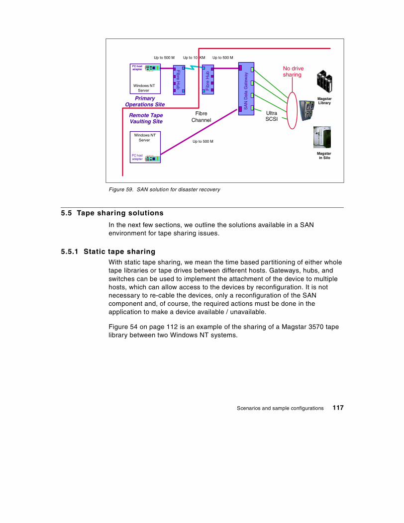
Figure 59. SAN solution for disaster recovery
5.5 Tape sharing solutions
In the next few sections, we outline the solutions available in a SANenvironment for tape sharing issues.
5.5.1 Static tape sharingWith static tape sharing, we mean the time based partitioning of either wholetape libraries or tape drives between different hosts. Gateways, hubs, andswitches can be used to implement the attachment of the device to multiplehosts, which can allow access to the devices by reconfiguration. It is notnecessary to re-cable the devices, only a reconfiguration of the SANcomponent and, of course, the required actions must be done in theapplication to make a device available / unavailable.
Figure 54 on page 112 is an example of the sharing of a Magstar 3570 tapelibrary between two Windows NT systems.
Windows NTServer
FC hostadapter
Windows NTServer
FC hostadapter
Fib
reH
ub
Remote TapeVaulting Site
PrimaryOperations Site
Up to 10 KMUp to 500 M
FibreChannel
Fibre
Hub
Up to 500 M
SA
ND
ata
Gat
eway
MagstarLibrary
Magstarin Silo
UltraSCSI
No drivesharing
Up to 500 M
Scenarios and sample configurations 117

5.5.2 Homogeneous tape sharingTivoli Storage Manager with its tape sharing function supports heterogeneouslibrary sharing so that multiple Tivoli Storage Manager servers of mixedplatforms can share the same library. It allows you to have essentially asmany Tivoli Storage Manager server as you need, without needing to installtape libraries on each server machine. Reasons for using multiple additionalTivoli Storage Manager server hosts are, for example, load balancing, testing,and server take-over. An additional advantage is that the Tivoli StorageManager tape sharing function reduces the numbers of tape drives requiredin a configuration, since the drives can be shared between the servers.
Figure 60 shows a tape pooling solution with the attachment of seven TivoliStorage Manager/NT servers attached to a single Magstar 3494 tape librarythrough a Fibre Channel Switch and a SAN Data Gateway. The servers do nothave to be of the same platform.
Figure 60. Tape pooling solution
Magstar 3494Tape Library
FCS
wit
ch
Network
SA
ND
ata
Gat
eway
FC hostadapter
WindowsNT Server
FC hostadapter
WindowsNT Server
TSM Library ServerF C hostadap ter
W indowsNT Server
F C hostadap ter
W indowsNT Server
FC hostadapter
WindowsNT Server
FC hostadapter
WindowsNT Server
FC hostadapter
WindowsNT Server
FC hostadapter
WindowsNT Server
FC hostadapter
WindowsNT Server
FC hostadapter
WindowsNT Server
FC hostadapter
WindowsNT Server
FC hostadapter
WindowsNT Server
118 Storage Area Networks: Tape Future in Fabrics

5.5.3 Heterogeneous tape sharingHeterogeneous Tape Sharing has a Library Server host controlling the tapedevices and libraries, allocating tape units, and managing tape cartridges forthe clients on the SAN. These clients are in principle any tape application:backup products like Tivoli Storage Manager, Legato, and others,user-developed tape applications (RYO), and also basic operating systembackup utilities, like mksysb in UNIX. This is illustrated on Figure 61.
Figure 61. Heterogenous tape sharing
5.6 Disk and tape on SAN
If you have a SAN with SAN-attached disks as well as SAN-attached tapedevices, you can use advanced functions like third-party copy between disksand tapes, but you can also only take advantage of the connectivity SANgives you to implement a generalized fail-over system.
Many installations have fail-over systems for the critical applications. Withdirect SCSI or SSA connections, where the devices can only be reached fromone or two systems, this often forces you to have several of these fail-oversystems, one per application. You don’t need to do this any more when youhave connectivity to all the SAN devices from a given host. One fail-oversystem can be used for all the applications having their data on the SAN, forexample, for Tivoli Storage Manager server and database servers, whetherthey require tape devices or not.
Windows NTServer
FChost
adapter
SA
ND
ata
Gat
eway
FibreChannel
UltraSCSI
3570
3570
500 m
25 m
Scenarios and sample configurations 119

120 Storage Area Networks: Tape Future in Fabrics

Appendix A. Fiber Channel discussion
Today, the industry considers Fibre Channel (FC) as the architecture onwhich most SAN implementations will be built. Fibre Channel is a technologystandard that allows data to be transferred from one network node to anotherat very high speeds. Current implementations transfer data at 100 MB/sec.The 200 MB/sec and 400 MB/sec data rates have already been tested. Thisstandard is backed by a consortium of industry vendors and has beenaccredited by the American National Standards Institute (ANSI). Manyproducts are now on the market that take advantage of FC’s high-speed,high-availability characteristics.
Note that the word Fibre in Fibre Channel is spelled in the French way ratherthan the American way. This is because the interconnections between nodesare not necessarily based on fiber optics, but can also be based on coppercables.
Some people refer to Fibre Channel architecture as the Fibre version of SCSI.Fibre Channel is an architecture used to carry IPI traffic, IP traffic, FICONtraffic, FCP (SCSI) traffic, and possibly traffic using other protocols, all at thesame level on the standard FC transport. An analogy could be ethernet,where IP, NetBIOS, and SNA are all used simultaneously over a singleEthernet adapter, since these are all protocols with mappings to ethernet.Similarly, there are many protocols mapped onto FC.
FICON is expected to be the standard protocol for S/390, and FCP is theexpected standard protocol for the non-S/390 systems, both using FibreChannel architecture to carry the traffic.
In the following sections, we will introduce some basic Fibre Channelconcepts, starting with the physical layer and proceeding to define theservices offered.
A.1 Layers
Fibre Channel is structured in independent layers, as are other networkingprotocols. There are five layers, where 0 is the lowest layer. The physicallayers are 0 to 2, the upper layers are 3 and 4.
A.1.1 Lower layers
• FC-0 defines physical media and transmission rates. These include cablesand connectors, drivers, transmitters, and receivers.
© Copyright IBM Corp. 2000 121

• FC-1 defines encoding schemes. These are used to synchronize data fortransmission.
• FC-2 defines the framing protocol and flow control. This protocol isself-configuring and supports point-to-point, arbitrated loop, and switchedtopologies.
A.1.2 Upper layers
Fibre Channel is a transport service that moves data fast and reliablybetween nodes. The two upper layers enhance the functionality of FibreChannel and provide common implementations for interoperability.
• FC-3 defines common services for nodes. One defined service underdevelopment is multicast, to deliver one transmission to multipledestinations.
• FC-4 defines upper layer protocol mapping. Protocols such as FCP(SCSI), FICON, and IP can be mapped to the Fibre Channel transportservice.
A.2 Topologies
Fibre Channel interconnects nodes using three physical topologies that canhave variants. Topologies include:
• Point-to-point — The point-to-point topology consists of a singleconnection between two nodes. All the bandwidth is dedicated for thesetwo nodes.
• Loop — In the loop topology, the bandwidth is shared between all thenodes connected to the loop. The loop can be wired node-to-node;however, if a node fails or is not powered on, the loop is out of operation.This is overcome by using a hub. A hub opens the loop when a new nodeis connected and closes it when a node disconnects.
• Switched — A switch allows multiple concurrent connections betweennodes. There can be two types of switches, circuit switches and frameswitches. Circuit switches establish a dedicated connection between twonodes, whereas frame switches route frames between nodes andestablish the connection only when needed. A switch can handle allprotocols, as it does not look at the Fibre Channel layer FC-4.
122 Storage Area Networks: Tape Future in Fabrics
A.3 Classes of Service
Fibre Channel provides a logical system of communication called Classes ofService, which are allocated by various Login protocols. The following fiveclasses of service are defined:
• Class 1 — Acknowledged Connection Service
Dedicates connections through fabric equivalent of a dedicated physicallink and delivers frames with acknowledgment in the same order astransmitted.
• Class 2 — Acknowledged Connectionless Service
Multiplexes frames from multiple sources with acknowledgment. Frameorder is not guaranteed.
• Class 3 — Unacknowledged Connectionless Service
Same as class 2, without frame acknowledgment. Flow has to becontrolled at buffer level.
• Class 4 — Fractional Bandwidth Connection Oriented Service
Same as class 1, but with only a minimum of bandwidth guaranteed. Ifsufficient bandwidth is available, class 2 and 3 frames will shareconnections.
• Class 6 — Simplex Connection Service
Same as class 1, but also provides multicast and preemption.
A.4 SAN components
As mentioned earlier, the industry considers Fibre Channel as thearchitecture on which most SAN implementations will be built, with FICON asthe standard protocol for S/390 systems, and FCP as the standard protocolfor non-S/390 systems. Based on this perception, the SAN componentsdescribed in the following sections will be Fibre Channel based.
A.4.1 SAN servers
The server infrastructure is the underlying reason for all SAN solutions.This infrastructure includes a mix of server platforms such as Windows NT,UNIX (various flavors) and OS/390. With initiatives such as ServerConsolidation and e-business, the need for SAN will increase. Although theearly SAN solutions only supported homogeneous environments, SAN willevolve into a truly heterogeneous environment.
Fiber Channel discussion 123

A.4.2 SAN storage
The storage infrastructure is the foundation on which information relies andtherefore must support a company’s business objectives and business model.In this environment, simply deploying more and faster storage devices is notenough; a new kind of infrastructure is needed, one that provides moreenhanced network availability, data accessibility, and system manageabilitythan is provided by today’s infrastructure.
The SAN meets this challenge by liberating the storage device, so it is not ona particular server bus, and attaches it directly to the network. In other words,storage is externalized and functionally distributed across the organization.The SAN also enables the centralizing of storage devices and the clusteringof servers, which makes for easier and less expensive administration.
A.5 SAN interconnects
The first element that must be considered in any SAN implementation is theconnectivity of storage and server components using technologies such asFibre Channel. The components listed below have typically been used forLAN and WAN implementations. SANs, like LANs, interconnect the storageinterfaces together into many network configurations and across longdistances.
Much of the terminology used for SAN has its origin in IP networkterminology. In some cases, the industry and IBM use different terms thatmean the same thing, and in some cases, mean different things. For example,after reading the sections A.5.10, “Bridges” on page 127 and A.5.11,“Gateways” on page 127, you will find that the IBM SAN Data Gateway isreally a bridge, not a gateway.
A.5.1 Cables and connectors
As with parallel SCSI and traditionalnetworking, there are different types ofcables of various lengths for use in a FibreChannel configuration. Two types of cablesare supported: copper and optical (fiber).Copper cables are used for short distances(up to 30m) and can be identified by theirDB9 (9-pin) connector. Fiber cables come in two distinct types: Multi-Modefiber (MMF) for short distances (up to 2 km), and Single-Mode Fiber (SMF) forlonger distances (up to 10km). IBM will support the following distances shownin Table 6 for FCP.
124 Storage Area Networks: Tape Future in Fabrics

Table 6. Cable and connector distances
In addition, connectors (see A.5.3, “Gigabit Interface Converters (GBIC)” onpage 125) and cable adapters (see A.5.4, “Media Interface Adapters (MIA)”on page 125) have been developed that allow the interconnection of fiberoptic based adapters with copper based devices.
A.5.2 Gigabit Link Model (GLM)
Gigabit Link Models are generic FibreChannel transceiver units that integrate thekey functions necessary for installation of aFibre Channel media interface on mostsystems.
A.5.3 Gigabit Interface Converters (GBIC)
Gigabit Interface Converters are typicallyused with hubs and switches, and allow bothcopper and fiber optics to connect up to thesame hub or switch. This works well in anenvironment where the components to beattached may be both fiber optics andcopper, depending on cost and distancerequirements.
A.5.4 Media Interface Adapters (MIA)
Media Interface Adapters can be used tofacilitate conversion of an optical interfaceconnection to copper and vice versa.Typically, MIAs are attached to host busadaptors, but can also be used with switchesand hubs. When a hub or switch onlysupports copper or optical connections, MIAscan be used to convert the signal to the appropriate media type (copper oroptical).
Diameter(Microns) Mode Laser type Distance
9 Single-mode Longwave <=10 km
50 Multi-mode Shortwave <=500 m
62.5 Multi-mode Shortwave <=175 m
Fiber Channel discussion 125

A.5.5 Adapters
Adapters are devices that connect to anetwork, server, or storage device and controlthe electrical protocol for communications.Adapters are also referred to as NetworkInterface Cards (NIC), Enterprise SystemsConnection (ESCON) adapters, Host BusAdapters (HBA), and SCSI host bus adapters.
A.5.6 Extenders
Extenders are used to facilitate longerdistances between nodes that exceed thetheoretical maximum.
A.5.7 Multiplexors
Multiplexors provide for more effectiveutilization of high speed bandwidth resourcesby interleaving data from multiple sourcesonto a single Link. An example of this wouldbe the FIbre CONnection Channel (FICON)Bridge, which allows up to eight separate ESCON paths to be multiplexedover a single FICON Link. The FICON bridge is not a separate box; as shownon the picture, it is a card in the ESCON Director. Multiplexors are alsobecoming increasingly efficient in terms of data compression, errorcorrection, transmission speed and multi-drop capabilities.
A.5.8 Hubs
Fibre Channel hubs are used to connect upto 126 nodes into a logical loop. Allconnected nodes share the bandwidth of this one logical loop. Fibre ChannelArbitrated Loop (FC-AL) protocol is the most widely accepted, cost-effectivealternative. Each port on a hub contains a Port Bypass Circuit (PBC) toautomatically open and close the loop to support hot pluggability. Multiplehubs and links can be implemented to provide alternate path failovercapability for high availability server environments. Intelligent hubs arecurrently being offered that provide features such as dynamic loopconfiguration and some of the benefits of switches.
126 Storage Area Networks: Tape Future in Fabrics

A.5.9 Routers
Storage routing is a new technology basedon the old concept of routing as it isunderstood by the data communicationsindustry. Storage routers differ from network routers in that the data beingrouted uses storage protocols like FCP (SCSI) instead of messagingprotocols such as TCP/IP. The data path used to transfer storage data may bethe same as that used for messaging traffic, but the content of the data itselfcontain imbedded storage protocol information. This is similar to the conceptof tunneling protocols used in the broader market. For example, a storagerouter could encapsulate SCSI information in TCP/IP packets for transmissionover an intervening ethernet network. The term routing implies data transfersover differing transmission media and addressing schemes. As a combinationof communications and storage channel capabilities, Fibre Channelrepresents the first opportunity to apply communication techniques, such asrouting, to storage traffic.
A.5.10 Bridges
Bridges facilitate communication betweenLAN/SAN segments and/or networks withdissimilar protocols. An example of thiswould be a FICON bridge, which allows ESCON protocol to be tunneled overFibre Channel protocol. FICON Bridges reduce the requirements of ESCONconnections, ESCON channels, ESCON Director ports, and so on; theysupport large and small block multiplexing.
A.5.11 Gateways
A gateway is a network station used tointerconnect two or more dissimilar networksor devices, and may or may not performprotocol conversion. These boxes are typically used to provide access toWAN from a LAN. With gateways, SANs can be extended across a WAN.
Note: The IBM SAN Data Gateway is used to attach SCSI devices like tapelibraries, disk subsystems at one end, and Fibre Channel connections at theother end, which makes it a router, not a gateway.
Fiber Channel discussion 127

A.5.12 Switches
Switches are among the highest performingdevices available for interconnecting largenumbers of devices, increasing bandwidth,reducing congestion and providing aggregatethroughput. Fibre Channel protocol wasdesigned specifically by the computerindustry to remove the barriers ofperformance with legacy channels and networks. When a Fibre Channelswitch is implemented in a SAN, the network is referred to as a fabric, orswitched fabric. Each device connected to a port on the switch can accessany other device connected to any other port on the switch, enabling anon-demand connection to every connected device. Various FC switchofferings support both switched fabric and/or loop connections. As thenumber of devices increases, multiple switches can be cascaded forexpanded access (fanout).
As switches allow any-to-any connections, the switch and managementsoftware can restrict which other ports a specific port can connect to. This iscalled port zoning.
A.5.13 Directors
When ESCON was announced, the switches were named directors, as theyincluded high availability and other features; for example, dual power supply,not included in traditional switches.
A.5.13.1 ESCONESCON transfers data in half duplex mode at a transfer rate of 17 MB/sec.The directors provide dynamic or static connections between attachedchannels, control units, devices, and other ESCON directors. ESCONDirectors provide single-link distances up to 3 km for multi-mode fiber and20 km for single-mode fiber.
The ESCON director supports the FICON bridge card mentioned in A.5.10,“Bridges” on page 127. Using the FICON bridge, an S/390 system can,through a FICON channel, communicate with ESCON control units anddevices attached to the director.
128 Storage Area Networks: Tape Future in Fabrics

A.5.13.2 FICONFICON transfers data in full duplex mode at a rate of 100 MB/sec. The FICONdirector is a regular Fibre Channel switch with some additional features. Itprovides connections between FICON channels and control units or deviceswith FICON interfaces. FICON Directors provide single-link distances up to550 meters for multi-mode fiber (50 or 62.5 micron) and 10 km (20 km withRPQ) for single-mode fiber (9 micron).
Fiber Channel discussion 129

130 Storage Area Networks: Tape Future in Fabrics

Appendix B. Terminology and other basics
This Appendix explains a few terms used in the book and also givesexplanations for SAN related topics.
B.1 StorWatch
StorWatch — IBM's Enterprise Storage Resource Management (ESRM)solution — is a growing software family whose goal is to enable storageadministrators to efficiently manage storage resources from any locationwithin an enterprise. Widely dispersed, disparate storage resources willultimately be viewed and managed through a single, cohesive control point.
Agent
In the client-server model, this is the part of the system that performsinformation preparation and exchange on behalf of a client or serverapplication. An example is the Agent SW installed on the SAN Data Gatewayto talk to the StorWatch Data Gateway Specialist.
StorWatch Expert
These are StorWatch applications that employ a 3 tiered architecture thatincludes a management interface, a StorWatch manager, and agents that runon the storage resource(s) being managed. Expert products employ aStorWatch data base that can be used for saving key management data (forexample, capacity or performance metrics). Expert products use the agents,as well as analysis of storage data saved in the data base, to perform highervalue functions such as reporting of capacity, performance, and so on, overtime (trends), configuration of multiple devices based on policies, monitoringof capacity and performance, automated responses to events or conditions,and storage related data mining.
StorWatch Reporter
StorWatch Reporter reduces disk management costs and increases theproductivity of storage administrators.
StorWatch Reporter creates an inventory and collects disk capacity andutilization data for heterogeneous PC, UNIX, and OS/390 servers residingacross your network. You can then generate customized reports that helpyou:
© Copyright IBM Corp. 2000 131

• Understand your present disk capacity and utilization• Identify trends in your storage usage• Anticipate and avoid outages due to out-of-storage conditions• Plan for growth in your enterprise
Reporter also locates and launches Web based storage software applicationsfor centralized administration of storage software and hardware.
StorWatch Specialist
A StorWatch interface for managing an individual Fibre Channel device or alimited number of like devices (that can be viewed as a single group).Storwatch specialists typically provide simple, point-in-time managementfunctions such as configuration, reporting on asset and status information,simple device and event monitoring, and perhaps some service utilities.
B.2 SCSI
SCSI
Small Computer System Interface — A set of evolving ANSI standardelectronic interfaces that allow personal computers to communicate withperipheral hardware such as disk drives, tape drives, CD_ROM drives,printers, and scanners, faster and more flexibly than previous interfaces.Table 7 below identifies the major characteristics of the different SCSIversions.
Table 7. Characteristics of different SCSI versions
SCSI Version SignalingRate(MHz)
BusWidth(bits)
Max. DTR(MB/s)
Max.NumberDevices
Max.CableLength
SCSI-1 5 8 5 7 6m
SCSI-2 5 8 5 7 6m
Wide SCSI-2 5 16 10 15 6m
Fast SCSI-2 10 8 10 7 6m
Fast Wide SCSI-2 10 16 20 15 6m
Ultra SCSI 20 8 20 7 1.5m
Ultra SCSI-2 20 16 40 7 12m
Ultra2 LVD SCSI 40 16 18 15 12m
132 Storage Area Networks: Tape Future in Fabrics

SCSI-3
SCSI-3 consists of a set of primary commands and additional specializedcommand sets to meet the needs of specific device types. The SCSI-3command sets are used not only for the SCSI-3 parallel interface but foradditional parallel and serial protocols, including Fibre Channel, Serial BusProtocol (used with IEEE 1394 Firewire physical protocol) and the SerialStorage Protocol (SSP).
SES
SCSI Enclosure Services — ANSI SCSI-3 proposal that defines a commandset for soliciting basic device status (temperature, fan speed, power supplystatus, etc.) from a storage enclosures.
B.3 Fibre Channel terms
E-Port
Expansion Port — a port on a switch used to link multiple switches togetherinto a Fibre Channel switch fabric.
F-Node
Fabric Node — a fabric attached node.
F-Port
Fabric Port — a port used to attach a Node Port (N_Port) to a switch fabric.
FL-Port
Fabric Loop Port — the access point of the fabric for physically connectingthe user's Node Loop Port (NL_Port).
G-Port
Generic Port — a generic switch port that either a Fabric Port (F_Port) or anExpansion Port (E_Port) function is automatically determined during login.
L-Port
Loop Port — A node or fabric port capable of performing Arbitrated Loopfunctions and protocols. NL-Ports and FL_Ports are loop-capable ports.
Terminology and other basics 133
N-Port
Node Port — A Fibre Channel-defined hardware entity at the end of a linkwhich provides the mechanisms necessary to transport information units to orfrom another node.
NL-Port
Node Loop Port — a node port that supports Arbitrated Loop devices.
Point-to-Point Topology
An interconnection structure in which each point has physical links to onlyone neighbor resulting in a closed circuit. In point-to-point topology, theavailable bandwidth the is dedicated.
Zoning
In Fibre Channel environments, the grouping together of multiple ports toform a virtual private storage network. Ports that are members of a group orzone can communicate with each other but are isolated from ports in otherzones.
134 Storage Area Networks: Tape Future in Fabrics
Appendix C. Special notices
This publication is intended to help customers, Business Partners, and IBMtechnical professionals to understand and apply the Storage Area Network(SAN) concepts related to IBM tape library products. The information in thispublication is not intended as the specification of any programming interfacesthat are provided by described products. See the PUBLICATIONS section ofthe IBM Programming Announcement for each described product for moreinformation about what publications are considered to be productdocumentation.
References in this publication to IBM products, programs or services do notimply that IBM intends to make these available in all countries in which IBMoperates. Any reference to an IBM product, program, or service is notintended to state or imply that only IBM's product, program, or service may beused. Any functionally equivalent program that does not infringe any of IBM'sintellectual property rights may be used instead of the IBM product, programor service.
Information in this book was developed in conjunction with use of theequipment specified, and is limited in application to those specific hardwareand software products and levels.
IBM may have patents or pending patent applications covering subject matterin this document. The furnishing of this document does not give you anylicense to these patents. You can send license inquiries, in writing, to the IBMDirector of Licensing, IBM Corporation, North Castle Drive, Armonk, NY10504-1785.
Licensees of this program who wish to have information about it for thepurpose of enabling: (i) the exchange of information between independentlycreated programs and other programs (including this one) and (ii) the mutualuse of the information which has been exchanged, should contact IBMCorporation, Dept. 600A, Mail Drop 1329, Somers, NY 10589 USA.
Such information may be available, subject to appropriate terms andconditions, including in some cases, payment of a fee.
The information contained in this document has not been submitted to anyformal IBM test and is distributed AS IS. The information about non-IBM("vendor") products in this manual has been supplied by the vendor and IBMassumes no responsibility for its accuracy or completeness. The use of thisinformation or the implementation of any of these techniques is a customerresponsibility and depends on the customer's ability to evaluate and integrate
© Copyright IBM Corp. 2000 135

them into the customer's operational environment. While each item may havebeen reviewed by IBM for accuracy in a specific situation, there is noguarantee that the same or similar results will be obtained elsewhere.Customers attempting to adapt these techniques to their own environmentsdo so at their own risk.
Any pointers in this publication to external Web sites are provided forconvenience only and do not in any manner serve as an endorsement ofthese Web sites.
Any performance data contained in this document was determined in acontrolled environment, and therefore, the results that may be obtained inother operating environments may vary significantly. Users of this documentshould verify the applicable data for their specific environment.
This document contains examples of data and reports used in daily businessoperations. To illustrate them as completely as possible, the examplescontain the names of individuals, companies, brands, and products. All ofthese names are fictitious and any similarity to the names and addressesused by an actual business enterprise is entirely coincidental.
Reference to PTF numbers that have not been released through the normaldistribution process does not imply general availability. The purpose ofincluding these reference numbers is to alert IBM customers to specificinformation relative to the implementation of the PTF when it becomesavailable to each customer according to the normal IBM PTF distributionprocess.
The following terms are trademarks of the International Business MachinesCorporation in the United States and/or other countries:
AIX AS/400AT DFSMSESCON IBMMagstar NetfinityOS/390 RS/6000S/390 SeascapeSP StorWatchSystem/390 Versatile Storage Server400
136 Storage Area Networks: Tape Future in Fabrics

The following terms are trademarks of other companies:
C-bus is a trademark of Corollary, Inc. in the United States and/or othercountries.
Java and all Java-based trademarks and logos are trademarks or registeredtrademarks of Sun Microsystems, Inc. in the United States and/or othercountries.
Microsoft, Windows, Windows NT, and the Windows logo are trademarks ofMicrosoft Corporation in the United States and/or other countries.
PC Direct is a trademark of Ziff Communications Company in the UnitedStates and/or other countries and is used by IBM Corporation under license.
ActionMedia, LANDesk, MMX, Pentium and ProShare are trademarks of IntelCorporation in the United States and/or other countries.
UNIX is a registered trademark in the United States and other countrieslicensed exclusively through The Open Group.
SET and the SET logo are trademarks owned by SET Secure ElectronicTransaction LLC.
Other company, product, and service names may be trademarks or servicemarks of others.
Special notices 137

138 Storage Area Networks: Tape Future in Fabrics

Appendix D. Related publications
The publications listed in this section are considered particularly suitable for amore detailed discussion of the topics covered in this redbook.
D.1 International Technical Support Organization publications
For information on ordering these ITSO publications see “How to get ITSOredbooks” on page 141.
• Introduction to Storage Area Network, SAN, SG24-5470
• Tivoli Storage Manager Version 3.7: Technical Guide, SG24-5477
• Magstar MP 3575 Tape Library Dataserver: Multiplatform Implementation,SG24-4983
• IBM Magstar Tape Products Family: A Practical Guide, SG24-4632
D.2 Redbooks on CD-ROMs
Redbooks are also available on the following CD-ROMs. Click the CD-ROMsbutton at http://www.redbooks.ibm.com/ for information about all the CD-ROMsoffered, updates and formats.
CD-ROM Title Collection KitNumber
System/390 Redbooks Collection SK2T-2177
Networking and Systems Management Redbooks Collection SK2T-6022
Transaction Processing and Data Management Redbooks Collection SK2T-8038
Lotus Redbooks Collection SK2T-8039
Tivoli Redbooks Collection SK2T-8044
AS/400 Redbooks Collection SK2T-2849
Netfinity Hardware and Software Redbooks Collection SK2T-8046
RS/6000 Redbooks Collection (BkMgr) SK2T-8040
RS/6000 Redbooks Collection (PDF Format) SK2T-8043
Application Development Redbooks Collection SK2T-8037
IBM Enterprise Storage and Systems Management Solutions SK3T-3694
© Copyright IBM Corp. 2000 139

D.3 Other Publications
These publications are also relevant as further information sources:
• IBM SAN Data Gateway Installation and User’s Guide, SC26-7304
• IBM SAN Fibre Channel Switch 2109 S16 User’s Guide, SC26-7351
• IBM SAN Fibre Channel Switch 2109 S08 User’s Guide, SC26-7349
140 Storage Area Networks: Tape Future in Fabrics

How to get ITSO redbooks
This section explains how both customers and IBM employees can find out about ITSO redbooks,redpieces, and CD-ROMs. A form for ordering books and CD-ROMs by fax or e-mail is also provided.
• Redbooks Web Site http://www.redbooks.ibm.com/
Search for, view, download, or order hardcopy/CD-ROM redbooks from the redbooks Web site. Alsoread redpieces and download additional materials (code samples or diskette/CD-ROM images) fromthis redbooks site.
Redpieces are redbooks in progress; not all redbooks become redpieces and sometimes just a fewchapters will be published this way. The intent is to get the information out much quicker than theformal publishing process allows.
• E-mail Orders
Send orders by e-mail including information from the redbooks fax order form to:
• Telephone Orders
• Fax Orders
This information was current at the time of publication, but is continually subject to change. The latestinformation may be found at the redbooks Web site.
In United StatesOutside North America
e-mail [email protected] information is in the “How to Order” section at this site:http://www.elink.ibmlink.ibm.com/pbl/pbl/
United States (toll free)Canada (toll free)Outside North America
1-800-879-27551-800-IBM-4YOUCountry coordinator phone number is in the “How to Order”section at this site:http://www.elink.ibmlink.ibm.com/pbl/pbl/
United States (toll free)CanadaOutside North America
1-800-445-92691-403-267-4455Fax phone number is in the “How to Order” section at this site:http://www.elink.ibmlink.ibm.com/pbl/pbl/
IBM employees may register for information on workshops, residencies, and redbooks by accessingthe IBM Intranet Web site at http://w3.itso.ibm.com/ and clicking the ITSO Mailing List button.Look in the Materials repository for workshops, presentations, papers, and Web pages developedand written by the ITSO technical professionals; click the Additional Materials button. Employees mayaccess MyNews at http://w3.ibm.com/ for redbook, residency, and workshop announcements.
IBM Intranet for Employees
© Copyright IBM Corp. 2000 141

IBM Redbook Fax Order Form
Please send me the following:
We accept American Express, Diners, Eurocard, Master Card, and Visa. Payment by credit card notavailable in all countries. Signature mandatory for credit card payment.
Title Order Number Quantity
First name Last name
Company
Address
City Postal code
Telephone number Telefax number VAT number
Invoice to customer number
Country
Credit card number
Credit card expiration date SignatureCard issued to
142 Storage Area Networks: Tape Future in Fabrics

Index
AAccelis 48access control 90, 98
definition 102access prevention 66Acknowledged
Connection 123Connectionless 123
administrative group 100AIX FC Adapter 92AIX location code 96AIX ost 96alerts 64ANSI 121arbitrated loop 122, 126archive server 70asset management 62Atape 94auto-share feature 23, 46, 74availability considerations 112
BB11 Magstar 3590 45B1A Magstar 3590 45backup server 33, 35, 70bridge 124, 126bus 81business
model 124objectives 124
Ccascade 51, 128cfgmgr 97Class 1 123Class 2 123Class 3 123Class 4 123Class 6 123command
device management 105Discover Net 89, 101fcShowDevs 95, 106mapRebuildDatabase 106mapShowDatabase 105
© Copyright IBM Corp. 2000
mapShowDevs 106mapWinnowDatabase 106scsiRescan 106scsiShow 106targets 106update firmware 89
command and control interface 83configuration 102configuration management 62connectivity 20connectivity layer 50control commands 107control unit 128copper 121, 124, 125
Ddevice and event monitoring 63device configuration 81device level management 60device management commands 105device map 81, 82diagnostic commands 107disaster recovery 24distance 124, 129distance solutions 109download firmware 104drive preemption 76dual power supply 128dynamic tape library sharing 75
EE11 Magstar 3590 45E1A Magstar 3590 45e-business 123electronic vaulting 68Emulex LP7000 58encoding 122Enterprise Storage Server 47ESCON 126, 127ESCON Director 126, 127Ethernet 127Ethernet commands 106Ethernet subnet 88Events submenu 102
143

Ffabric 128fabric topology discovery 61fail-over
automatic 25capability with hubs 126
failure in a FC 112fanout 128FC #6227 58FC target 81FC-0 121FC-1 122FC-2 122FC-3 122FC-4 122FC-AL 126FCP 121, 122, 123, 127FCP indication 96fcShowDevs 84fiber 121, 124, 125fiber cable
required specifications 109Fibre Channel 121, 122, 123, 124, 125, 127, 128Fibre Channel RAID Storage Server 46FICON 43, 121, 122, 123, 126, 127, 128
bridge 128firmware update 89flow control 122Fractional Bandwidth Connection 123frame switch 122framing protocol 122
Ggateway 124Gateway LUN 95GBIC 57Gigabit Interface Converter
see GBIC
Hhard ID 83HBA 26, 58, 126health check 101health check commands 107heterogeneous 123homogeneous 123Host Bus Adapters
see HBA
host FC cables 87hosts
number of 20hotfixes 86hub 8, 122, 125
intelligent 126
II/O bus 96IBM 2103-H07 57IBM 2108 51, 52IBM 2108-R03 56IBM 3570
number of host attachments 45IBM Fibre Channel Hub 109IBM Fibre Channel Storage Hub 57IBM Magstar 3575 44IBM SAN Data Gateway 43, 52IBM SAN Data Gateway Router 56IBM SAN Fibre Channel Switch 43, 51IBM SAN Initiative 41inband interface 60infrastructure 124install the HBA 87installation checklist 85intelligent tape subsystem 38interoperability 78interoperability laboratories 79inventory of resources 61IP 121, 122
network terminology 124
LLAN 124, 127LAN-less backup 27library clients 75library partitioning 45library server 75library sharing 21Linear Tape - Open
see LTOLIP 16
see Loop Initialization Processload balancing 70load configuration 102location code 96logical library 45Logical Unit Number
144 Storage Area Networks: Tape Future in Fabrics

see LUNloop 122, 128Loop Initialization Process 8LTO 48LTO-CM (Cartridge Memory) 49LUN 81LUN number
mapping with SAN Data Gateway 95LUN zoning 98LUNs
maximum number of 84table of devices 98
MMagstar 3590 45
auto-share 46twin-tail 46
Magstar MP 3570 44Magstar MP 3575
logical library 45Magstar VTS 36manage drive allocation 74management software 20meta-data 27MMF 124mulit-path feature 21multicast 31, 33, 122, 123multi-drop 126multi-mode 124, 129
Nnative fibre-channel 48NetBIOS 121Netmask 88network device driver interface number 93NIC 126node-to-node 122
OOS/390 123outband connect 99outband interface 60
Ppartitioning libraries 65partitioning of resources 65PBC 126
persistent address mapping table 105physical media 121point-in-time backup 25point-to-point 122pooling 22port zoning 98preemption 123pseudo target ID 84
Qq drive 84Qlogic 2100F 58QLogic card 87
Rre-boot Gateway 100redundant tape subsystem 25Removable Media Manager 77reporting utilities 61RESERVE 74restart Gateway 103router 127RS/6000 FC Adapter card 92RSM 77
SS/390 123, 128SAN
definition of 4elements 4exploitation 3see Storage Area Networksolutions 19
SAN Data Gatewaycomparison with Hub 56name 88sharing between disk and tape 53
San Data Gatewaycomparison with Switch 56
SAN Data Gateway configuration 90save configuration 90, 102SCSI 121, 122, 126, 127SCSI address
components 81SCSI LUN 95SCSI port 20SCSI-3 29
145
server consolidation 123server-free backup 28
data flow 29service point terminal 84service port interface 104share
IBM 3494 23sharing
library 11media 11tape drive 11
sharing between heterogeneous applications 75Simplex Connection 123single-mode 124, 129SMF 124SNA 121SNIA Extended Copy Command specification 54SNMP 64specialist client 88specialist server 88static tape sharing 117Storage Area NetworkStorWatch expert 60StorWatch SAN Data Gateway Specialist 62, 98
prerequisites 65switch 8, 122, 125, 126switched 122, 128switched fabric management 61
Ttape
pooling 22process automation 20sharing 20vaulting 109
target ID 81TCP/IP 127third party copy 28Tivoli Removable Media Manager 77Tivoli SAN Manager 62transition products 43transmission rates 121transport service 122tunneling 127twin-tail feature 46
UUltrium 48
specifications 49Unacknowledged Connectionless 123UNIX 123
Vvalidation server 70verify target devices 88Virtual Tape Server
see VTSVital Product Data 61VTS 36
WWAN 124, 127Windows NT 123world-wide name
see WWNWWN 83
Zzoning 65, 98, 128zoning definition example 103
146 Storage Area Networks: Tape Future in Fabrics

© Copyright IBM Corp. 2000 147
IBM Redbooks evaluation
Storage Area Networks: Tape Future in FabricsSG24-5474-00
Your feedback is very important to help us maintain the quality of IBM Redbooks. Please complete thisquestionnaire and return it using one of the following methods:
• Use the online evaluation form found at http://www.redbooks.ibm.com/• Fax this form to: USA International Access Code + 1 914 432 8264• Send your comments in an Internet note to [email protected]
Which of the following best describes you?_ Customer _ Business Partner _ Solution Developer _ IBM employee_ None of the above
Please rate your overall satisfaction with this book using the scale:(1 = very good, 2 = good, 3 = average, 4 = poor, 5 = very poor)
Overall Satisfaction __________
Please answer the following questions:
Was this redbook published in time for your needs? Yes___ No___
If no, please explain:
What other redbooks would you like to see published?
Comments/Suggestions: (THANK YOU FOR YOUR FEEDBACK!)

Printed in the U.S.A.
SG24-5474-00
StorageA
reaN
etworks:
Tap
eF
uturein
Fabrics
SG
24-5474-00
®