Embed Size (px)
Citation preview

SDH04A STM-4 Based ADM Data, E1/T1, E3, FE, GbE Add Drop Multiplexer


CTC Union Technologies Co., Ltd. Far Eastern Vienna Technology Center (Neihu Technology Park) 8F, No. 60 Zhouzi St. Neihu District Taipei 114 Taiwan Tel: +886-2-26591021 Fax: +886-2-27991355 Email: [email protected] URL: http://www.ctcu.com SDH04A User Manual STM-4 Based Add Drop Multiplexer Version 1.0 Dec. 2009 (Release) Version 2.0 Aug. 2010 (Update) Copyright © 2009~2010, CTC Union Technologies, Inc. All rights reserved.
All specifications are subject to change without prior notice.

Legal The information in this publication has been carefully checked and is believed to be entirely accurate at the
time of publication. CTC Union Technologies assumes no responsibility, however, for possible errors or omissions, or for any consequences resulting from the use of the information contained herein. CTC Union Technologies reserves the right to make changes in its products or product specifications with the intent to improve function or design at any time and without notice and is not required to update this documentation to reflect such changes.
CTC Union Technologies makes no warranty, representation, or guarantee regarding the suitability of its
products for any particular purpose, nor does CTC Union assume any liability arising out of the application or use of any product and specifically disclaims any and all liability, including without limitation any consequential or incidental damages.
CTC Union products are not designed, intended, or authorized for use in systems or applications intended to
support or sustain life, or for any other application in which the failure of the product could create a situation where personal injury or death may occur. Should the Buyer purchase or use a CTC Union product for any such unintended or unauthorized application, the Buyer shall indemnify and hold CTC Union Technologies and its officers, employees, subsidiaries, affiliates, and distributors harmless against all claims, costs, damages, expenses, and reasonable attorney fees arising out of, either directly or indirectly, any claim of personal injury or death that may be associated with such unintended or unauthorized use, even if such claim alleges that CTC Union Technologies was negligent regarding the design or manufacture of said product.
TRADEMARKS Microsoft is a registered trademark of Microsoft Corp. HyperTerminal™ is a registered trademark of Hilgraeve Inc. WARNING: This equipment has been tested and found to comply with the limits for a Class A digital device, pursuant to
Part 15 of the FCC Rules. These limits are designed to provide reasonable protection against harmful interference when the equipment is operated in a commercial environment. This equipment generates, uses, and can radiate radio frequency energy and if not installed and used in accordance with the instruction manual may cause harmful interference in which case the user will be required to correct the interference at his own expense. NOTICE: (1) The changes or modifications not expressively approved by the party responsible for compliance could void the user's authority to operate the equipment. (2) Shielded interface cables and AC power cord, if any, must be used in order to comply with the emission limits.
CISPR PUB.22 Class A COMPLIANCE: This device complies with EMC directive of the European Community and meets or exceeds the following
technical standard. EN 55022 - Limits and Methods of Measurement of Radio Interference Characteristics of Information Technology Equipment. This device complies with CISPR Class A.
CE NOTICE Marking by the symbol CE indicates compliance of this equipment to the EMC and LVD directives of the
European Community. Such marking is indicative that this equipment meets or exceeds the following technical standards: EN 55022:2006, Class A, EN55024:1998+A1:2001+A2:2003, and EN60950-1:2001
Chapter 1 . System Introductions...........................................................7 1.1 Functional Descriptions ....................................................................................7 1.2 System Features.......................................................................................... 10 1.3 System Functional Blocks ............................................................................... 11 1.4 Specifications.............................................................................................. 13
1.4.1 Optical Interface .................................................................................... 13 1.4.2 E1 Interface ......................................................................................... 13 1.4.3 T1 Interface ......................................................................................... 14 1.4.4 Ethernet Interface .................................................................................. 14 1.4.5 V.35 Interface ....................................................................................... 14 1.4.6 E3/T3 Interface ..................................................................................... 15 1.4.7 Management Interface............................................................................. 15 1.4.8 Connectors .......................................................................................... 15 1.4.9 Electricity Power Source .......................................................................... 16 1.4.10 Mechanical Dimension of SDH04A ............................................................ 16 1.4.11 LED Indicators..................................................................................... 17 1.4.12 Push Button ....................................................................................... 17 1.4.13 LCD Display ....................................................................................... 17 1.4.14 Office Alarm........................................................................................ 17 1.4.15 Environment Conditions ......................................................................... 17
Chapter 2 . System Applications..........................................................18 2.1 Applications................................................................................................ 18 2.2 Services on Network ..................................................................................... 19 2.3 EoS for E-LAN ............................................................................................ 20
Chapter 3 . Panel Description..............................................................21 3.1 SDH04A Front Panel Overview ......................................................................... 21
3.1.1 Tributary Status on LED ........................................................................... 21 3.1.2 Alarm Indication on LED........................................................................... 24 3.1.3 RJ-45 Pin Assignment for NMS Port ............................................................ 25 3.1.4 Console Craft ....................................................................................... 25 3.1.5 V.35 Interface Connector.......................................................................... 26 3.1.6 Optical Interface Indication on LED.............................................................. 26 3.1.7 RESET Push Button ............................................................................... 27 3.1.8 ACO Push Button .................................................................................. 27 3.1.9 LCD Panel and Keypads .......................................................................... 27 3.1.10 Alarm Output Interface ........................................................................... 27
3.2 Rear Panel Overview..................................................................................... 28 3.2.1 Power Connection.................................................................................. 28 3.2.2 Frame Ground ...................................................................................... 28 3.2.3 Electricity Power Switch ........................................................................... 29 3.2.4 Tributary Slot........................................................................................ 29
Chapter 4 . Installation ......................................................................30 4.1 Install Equipment and Start the System ............................................................... 30
4.1.1 Install AC Power .................................................................................... 30 4.1.2 Install DC Power.................................................................................... 30 4.1.3 Start the System .................................................................................... 30
4.2 Install Tributary Modules ................................................................................. 31 4.3 Management Interface ................................................................................... 31
4.3.1 Install Console Interface........................................................................... 31
Table of Contents
4.3.2 Install NMS Interface............................................................................... 31
4.4 Connect Cables ........................................................................................... 31 4.4.1 Connect Fiber Cable............................................................................... 31 4.4.2 Connect E-X/DS-X Cable ......................................................................... 31 4.4.3 GBE Interface Module ............................................................................. 32 4.4.4 QV35 Interface Module............................................................................ 32
4.5 Install Office Alarm........................................................................................ 32
Chapter 5 . Module Description ...........................................................33 5.1 AC/DC Pluggable Power Module ....................................................................... 33 5.2 4E1B: 4-channel E1 Interface Module ................................................................. 33 5.3 8E1R: 8 channel E1 Interface Module ................................................................. 34 5.4 ET3: 1-channel E3/DS3 Interface Module............................................................. 35 5.5 8ET: 8-channel E1/T1 Interface Module ............................................................... 35 5.6 QV35: 4-channel V.35 Interface Module............................................................... 36 5.7 GBE: 4-port 10/100/1000M Ethernet Interface Module.............................................. 36
Chapter 6 . System Operations............................................................37 6.1 Start and Reset System.................................................................................. 37
6.1.1 Power Supply ....................................................................................... 37 6.1.2 System Reset ....................................................................................... 37 6.1.3 System Provisioning & Default Settings ........................................................ 38
6.2 Performance Management .............................................................................. 40 6.3 Optical Interface Operation.............................................................................. 41 6.4 Alarm Management....................................................................................... 42 6.5 Alarm Event Log .......................................................................................... 42 6.6 E1 Interface Operation ................................................................................... 42 6.7 Time Interval Error (TIE) ................................................................................. 43 6.8 Ethernet Transmission ................................................................................... 43 6.9 Maintenance and Self-diagnostic Testing ............................................................. 44
6.9.1 Loopback Function................................................................................. 44 6.9.2 Self-diagnostic Testing............................................................................. 44
6.10 Administration Security ................................................................................. 44 6.11 System Management ................................................................................... 45
Chapter 7 . Network Management ........................................................46 7.1 NMS Interface and SNMP ............................................................................... 46 7.2 NMS Functions............................................................................................ 47 7.3 Console Craft.............................................................................................. 47 7.4 LCD Interface.............................................................................................. 48 7.5 Web Server Interface..................................................................................... 48
Appendix A. Ordering Information .......................................................70
Appendix B. Menu-Driven Operations ...................................................71
Appendix C. LCD Operations on for SDH04A........................................109
Appendix D. VLAN Function .............................................................115
Appendix E. Q-in-Q Function ............................................................117
Appendix F. Traffic Rate Control Function ...........................................120
Appendix G. Nx64K Grouping ...........................................................122
Appendix H. STM-4 GFP Mapping Rule ...............................................126
Appendix I. Alarm Category and Display .............................................128
- 7 -
Chapter 1. System Introductions
This chapter introduces SDH04A and describes the features, functions, and specifications.
1.1 Functional Descriptions
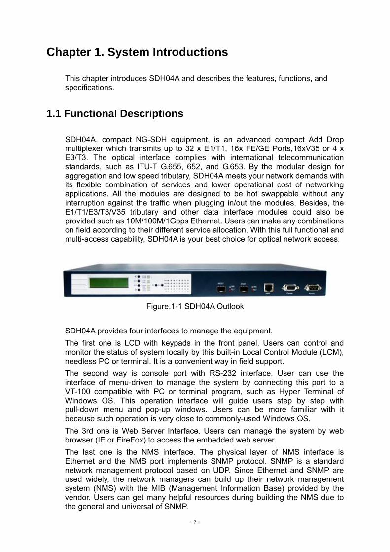
SDH04A, compact NG-SDH equipment, is an advanced compact Add Drop multiplexer which transmits up to 32 x E1/T1, 16x FE/GE Ports,16xV35 or 4 x E3/T3. The optical interface complies with international telecommunication standards, such as ITU-T G.655, 652, and G.653. By the modular design for aggregation and low speed tributary, SDH04A meets your network demands with its flexible combination of services and lower operational cost of networking applications. All the modules are designed to be hot swappable without any interruption against the traffic when plugging in/out the modules. Besides, the E1/T1/E3/T3/V35 tributary and other data interface modules could also be provided such as 10M/100M/1Gbps Ethernet. Users can make any combinations on field according to their different service allocation. With this full functional and multi-access capability, SDH04A is your best choice for optical network access.
Figure.1-1 SDH04A Outlook
SDH04A provides four interfaces to manage the equipment. The first one is LCD with keypads in the front panel. Users can control and monitor the status of system locally by this built-in Local Control Module (LCM), needless PC or terminal. It is a convenient way in field support. The second way is console port with RS-232 interface. User can use the interface of menu-driven to manage the system by connecting this port to a VT-100 compatible with PC or terminal program, such as Hyper Terminal of Windows OS. This operation interface will guide users step by step with pull-down menu and pop-up windows. Users can be more familiar with it because such operation is very close to commonly-used Windows OS. The 3rd one is Web Server Interface. Users can manage the system by web browser (IE or FireFox) to access the embedded web server. The last one is the NMS interface. The physical layer of NMS interface is Ethernet and the NMS port implements SNMP protocol. SNMP is a standard network management protocol based on UDP. Since Ethernet and SNMP are used widely, the network managers can build up their network management system (NMS) with the MIB (Management Information Base) provided by the vendor. Users can get many helpful resources during building the NMS due to the general and universal of SNMP.

- 8 -
This saves your extra cost and time while building the NMS. Users can even integrate the management system of SDH04A into existing SNMP NMS under operation. In addition to user’s NMS, there is also GUI NMS developed by CTC Union. that helps you to manage SDH04A machines in the network. All above-mentioned management interfaces support single-ended operation, which is that operators can manage both the equipments locally or remotely through the local site. The communication between local equipment and remote equipment uses DCC channel to send message to implement the system management. SDH04A provides security of administration for the safety consideration of system management. Administrator has the highest privilege and he is allowed to modify the operator’s privilege. He also can set the user names and passwords to create accounts that can access the network. This function can prevent the unauthorized users from accessing the network.
SDH04A provides auto alarm reports and office alarms relay contact to inform the manger for any unusual and abnormal conditions on the equipments and systems in order to let users easily identify the problem or recover the transmission network as soon as possible, if necessary. The alarms of SDH04A are divided into 3 levels by their alarm conditions: Critical alarm, Major alarm, and Minor alarm. The user can set the severity of all the alarms of SDH04A independently through Console, LCD, Web Server or NMS. All these alarms can activate the office alarms to inform the user in the office. Besides, there are also LED indicators on the front panel of SDH04A for visual identification for field maintenance purpose. The LED indicators include power, system alarms, optical alarms, tributary alarms, remote alarms, local alarms, ACO status and loopback indication, and so on.
In addition to alarm report, SDH04A implements the performance monitoring (PM Parameter) to monitor the transmission stability on both optical and electrical interfaces. Users can collect and analyze the data to get the transmission performance. All the parameters can be read and cleared through the Console, LCD, Web Server or NMS.
The protection of optical interface is important for optical transmission system. The SDH04A is equipped with two optical modules to provide 1+1 auto protection switch (APS) of optical interface. The system will switch the optical interface from the working line to stand-by line automatically when the working line fails due to loss of signal (LOS) or poor performance defined by the user prior. Users can also switch the optical line manually by Console, LCD, Web Server or NMS. For the system maintenance purpose, SDH04A provides two functions: Loopback and Self-diagnostic. Users can operate many kinds of loopback functions on the optical and E1/T1/E3/T3/V35/Ethernet interfaces through Console, LCD, Web Server or NMS to debug and identify the transmission problems of the network. By the loopback function and built-in E1/T1/E3/T3 PRBS signal generator and detector working together, SDH04A can operate the self-diagnostic testing for each E1/T1/E3/T3/V35 channel and get the BER.

- 9 -
SDH04A is designed for easy installation. It can be installed on a desktop or mounted in standard 19 inches or 23 inches (ETSI) racks from its stand-alone mechanical design. The height of stand-alone unit is less than 3.5 inches. The SDH04A complies with FCC Part 15 Subpart B Rules of U.S./CISPR 22 Class A for EMI and EN50082-1 for EMC. It also complies with IEC 61000-4-2 level 2 for ESD. At the mean time, it also complies with lighting surge protection standards, which meet IEC1000-4-5 class 3 or ANSI/TIA-968-A or FCC part 68 and ITU-T K.20, and K.21 standards for E1 and AC, DC power interfaces to protect.

SDH04A User Manual
- 10 -
1.2 System Features
Up to 32x E1/T1, 16x V.35, 16x FE/GE Ports or 4x E3/T3 interfaces over NG-SDH (STM1/4 ADM/TM & STM16 in the future).
Up to 4 tributary interface modules per unit. System configurations are stored in NVRAM. It does not use battery for
backup operation. System configurations are backed up automatically after each update and reloaded automatically when the tributary interface module is replaced or due to any other circumstances.
Hot swappable for each module without any interruption to the other working traffics when plugging in/out interface module.
Backup configurations in flash for system restart or power failure. Configuration files backup and restore. Provide a default configuration setup option for reset. Various kinds of service, such as E1/T1, E3/T3, V.35, 10/100M or 1G
Ethernet. Ethernet traffic is encapsulated and transported over SDH using Generic Framing Procedure (GFP) & Virtual Concatenation (VCAT).
Transparent E1 signal with HDB3/AMI line code. (The E1 parameters are field selectable by management interface).
Transparent E3/T3 signal with HDB3/B3ZS line code. (The E3/T3 parameters are field selectable by management interface).
EoS for E-LAN. Support Ethernet traffic in all nodes of rings. Single-ended network management. 1+1 APS for optical line and module (Requires equipping with 2 optical
modules.). LED indicators: power, office alarm, optical alarm, tributary status, remote
site alarm, loopback. LED indicator for remote site alarm. Office alarm & remote power failure alarm
Selectable connectors, wavelength, and system gain (≧12dB) for optical interface.
Alarm auto report and performance monitoring. Administration security with log-in/out by user name and password assigned
by supervisor. Menu-driven LCM, Web Server and SNMP management interfaces. Local and remote Loopback functions for optical and E1/T1/E3/T3/Ethernet
interfaces. Stand-alone type on 19 inches or 23 inches (ETSI) racks. Provides pluggable AC/DC power supply units for redundant operation and
work at load sharing basis.
SDH04A User Manual
- 11 -
1.3 System Functional Blocks
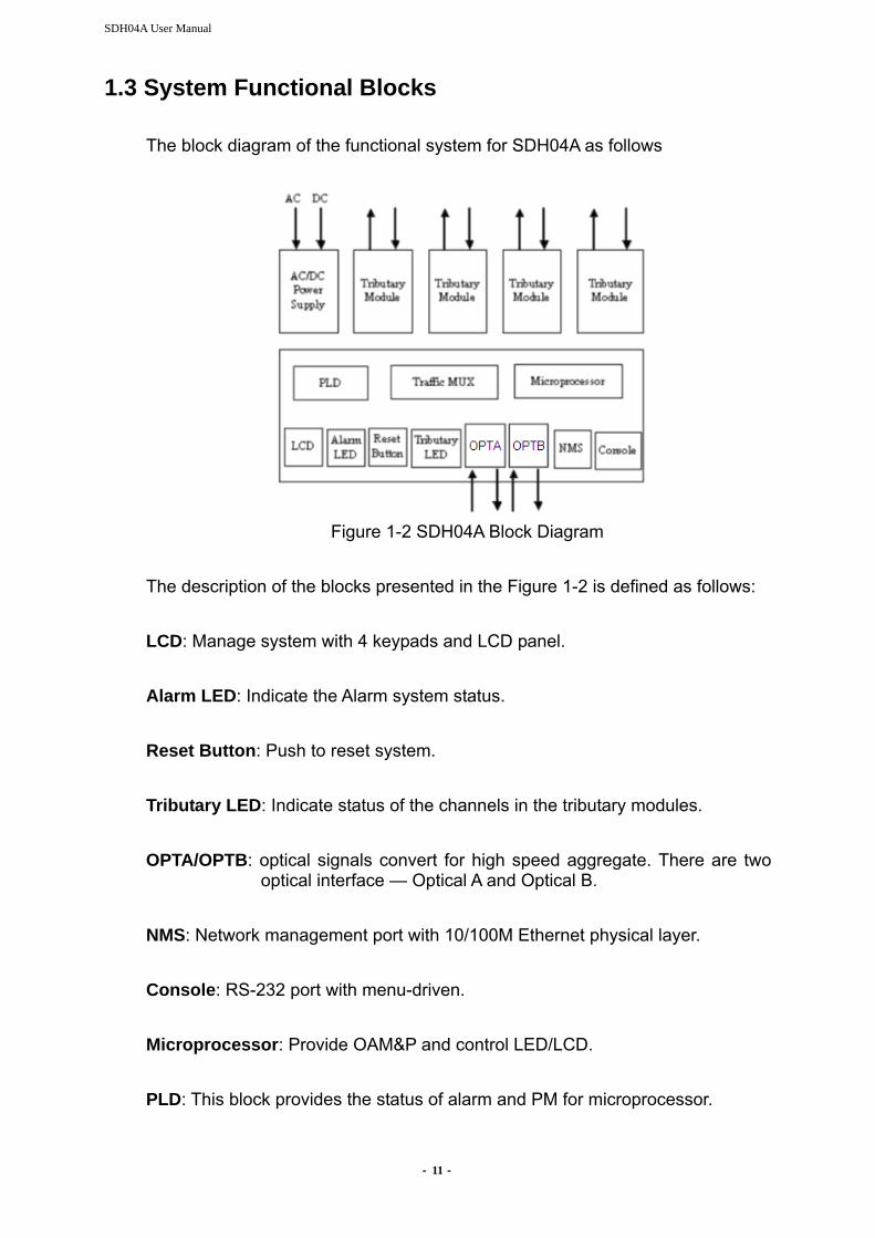
The block diagram of the functional system for SDH04A as follows
Figure 1-2 SDH04A Block Diagram
The description of the blocks presented in the Figure 1-2 is defined as follows: LCD: Manage system with 4 keypads and LCD panel. Alarm LED: Indicate the Alarm system status. Reset Button: Push to reset system. Tributary LED: Indicate status of the channels in the tributary modules. OPTA/OPTB: optical signals convert for high speed aggregate. There are two
optical interface — Optical A and Optical B. NMS: Network management port with 10/100M Ethernet physical layer. Console: RS-232 port with menu-driven. Microprocessor: Provide OAM&P and control LED/LCD. PLD: This block provides the status of alarm and PM for microprocessor.

- 12 -
Traffic MUX: This block implements the multiplexer/ de-multiplexer between low-speed and high-speed aggregated interfaces. Tributary Module: Each SDH04A provides 4 tributary slots for various kinds of modules like E1/T1/E3/T3/V35 and Ethernet. AC/DC Power Supply Module: Convert the 110V/220V AC or -48V DC to 9V DC power.
- 13 -
1.4 Specifications
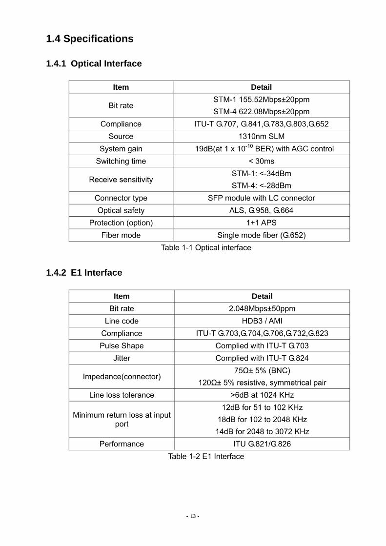
1.4.1 Optical Interface
Item Detail
Bit rate STM-1 155.52Mbps±20ppm STM-4 622.08Mbps±20ppm
Compliance ITU-T G.707, G.841,G.783,G.803,G.652 Source 1310nm SLM
System gain 19dB(at 1 x 10⁻¹⁰ BER) with AGC control Switching time < 30ms
Receive sensitivity STM-1: <-34dBm STM-4: <-28dBm
Connector type SFP module with LC connector Optical safety ALS, G.958, G.664
Protection (option) 1+1 APS Fiber mode Single mode fiber (G.652)
Table 1-1 Optical interface
1.4.2 E1 Interface
Item Detail Bit rate 2.048Mbps±50ppm
Line code HDB3 / AMI Compliance ITU-T G.703,G.704,G.706,G.732,G.823 Pulse Shape Complied with ITU-T G.703
Jitter Complied with ITU-T G.824
Impedance(connector) 75Ω± 5% (BNC)
120Ω± 5% resistive, symmetrical pair Line loss tolerance >6dB at 1024 KHz
Minimum return loss at input port
12dB for 51 to 102 KHz 18dB for 102 to 2048 KHz 14dB for 2048 to 3072 KHz
Performance ITU G.821/G.826 Table 1-2 E1 Interface
- 14 -
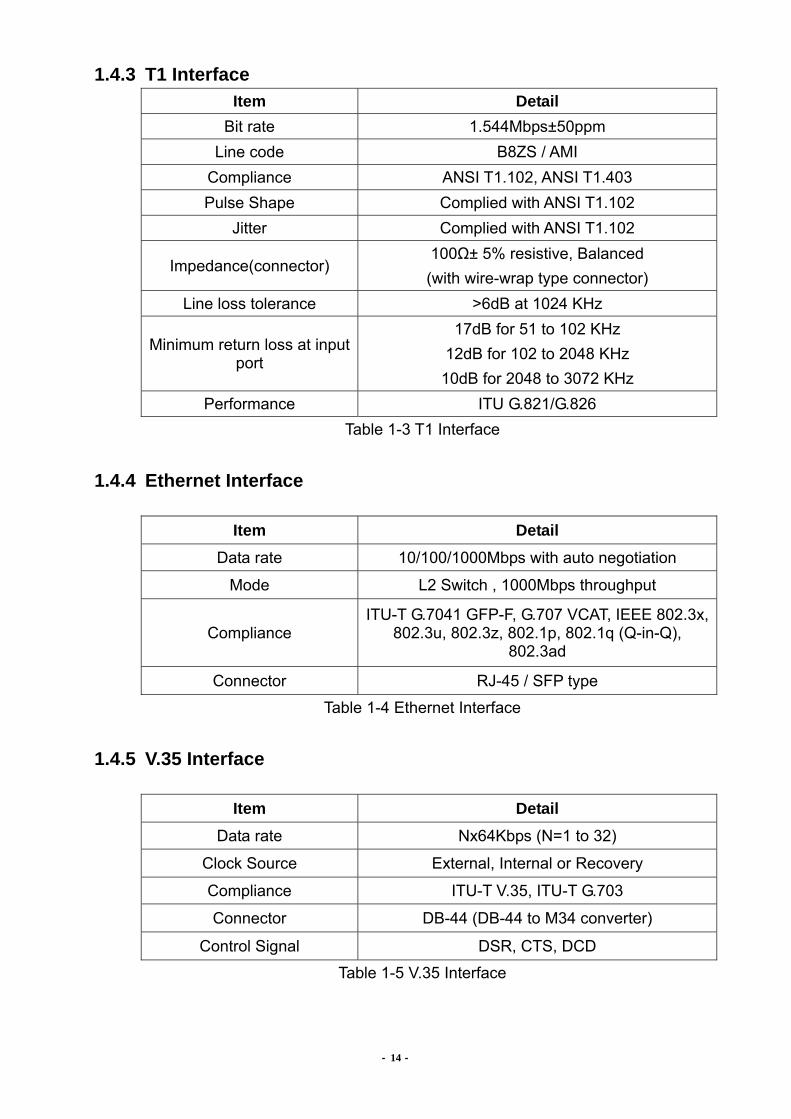
1.4.3 T1 Interface Item Detail
Bit rate 1.544Mbps±50ppm Line code B8ZS / AMI
Compliance ANSI T1.102, ANSI T1.403 Pulse Shape Complied with ANSI T1.102
Jitter Complied with ANSI T1.102
Impedance(connector) 100Ω± 5% resistive, Balanced (with wire-wrap type connector)
Line loss tolerance >6dB at 1024 KHz
Minimum return loss at input port
17dB for 51 to 102 KHz 12dB for 102 to 2048 KHz 10dB for 2048 to 3072 KHz
Performance ITU G.821/G.826 Table 1-3 T1 Interface
1.4.4 Ethernet Interface
Item Detail Data rate 10/100/1000Mbps with auto negotiation
Mode L2 Switch , 1000Mbps throughput
Compliance ITU-T G.7041 GFP-F, G.707 VCAT, IEEE 802.3x,
802.3u, 802.3z, 802.1p, 802.1q (Q-in-Q), 802.3ad
Connector RJ-45 / SFP type
Table 1-4 Ethernet Interface
1.4.5 V.35 Interface
Item Detail Data rate Nx64Kbps (N=1 to 32)
Clock Source External, Internal or Recovery
Compliance ITU-T V.35, ITU-T G.703
Connector DB-44 (DB-44 to M34 converter)
Control Signal DSR, CTS, DCD
Table 1-5 V.35 Interface

- 15 -
1.4.6 E3/T3 Interface
Item Detail Bit rate 34.368/44.736 Mbps±20ppm
Line code HDB3 / B3ZS Compliance ITU-T G.703, G.824,G.823 Pulse Shape Complied with ITU-T G.703
Jitter Complied with ITU-T G.824,823 Impedance(connector) 75Ω± 5% (BNC)
Table 1-6 E3/T3 Interface
1.4.7 Management Interface
Item Detail
Protocol VT-100 ANSI/ HTTP
Craft interface RS-232 Async. (EIA561)
HTTP 10/100 Base-T (RFC 1406)
LCD 2 X 16 (character display) LCD display with key control
Table 1-7 Management Interface
1.4.8 Connectors
Item Detail Optic SFP module with LC connector
RS-232 D-type 9-pin female
LAN RJ-45
Office alarm D-type 9-pin male
DC power Screw
Frame Ground Screw Table 1-8 Connectors

SDH04A User Manual
- 16 -
1.4.9 Electricity Power Source
Item Detail DC pluggable unit -36 ~ -72V AC pluggable unit 90~260V @ 47~63Hz
Power consumption <27W for SDH04A Table 1-9 Electricity Power Source
1.4.10 Mechanical Dimension of SDH04A
Item Detail Height 44mm Width 440mm Depth 312mm, (1U, Mount on19”/23”/ETSI rack) Weight 3.4Kg
Table 1-10 Mechanical Dimension
- 17 -
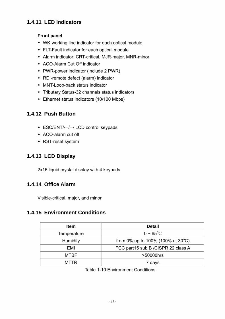
1.4.11 LED Indicators
Front panel WK-working line indicator for each optical module FLT-Fault indicator for each optical module Alarm indicator: CRT-critical, MJR-major, MNR-minor ACO-Alarm Cut Off indicator PWR-power indicator (include 2 PWR) RDI-remote defect (alarm) indicator MNT-Loop-back status indicator Tributary Status-32 channels status indicators Ethernet status indicators (10/100 Mbps)
1.4.12 Push Button
ESC/ENT/←/→ LCD control keypads ACO-alarm cut off RST-reset system
1.4.13 LCD Display
2x16 liquid crystal display with 4 keypads
1.4.14 Office Alarm
Visible-critical, major, and minor
1.4.15 Environment Conditions
Item Detail Temperature 0 ~ 65oC
Humidity from 0% up to 100% (100% at 30oC) EMI FCC part15 sub B /CISPR 22 class A
MTBF >50000hrs MTTR 7 days
Table 1-10 Environment Conditions
- 18 -
Chapter 2. System Applications
This chapter describes the topology application of SDH04A and its services on network.
2.1 Applications
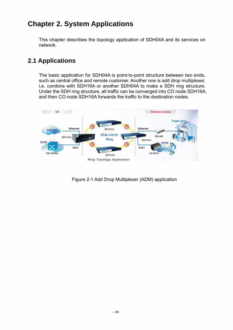
The basic application for SDH04A is point-to-point structure between two ends, such as central office and remote customer. Another one is add drop multiplexer, i.e. combine with SDH16A or another SDH04A to make a SDH ring structure. Under the SDH ring structure, all traffic can be converged into CO node SDH16A, and then CO node SDH16A forwards the traffic to the destination nodes.
Figure 2-1 Add Drop Multiplexer (ADM) application
- 19 -
2.2 Services on Network
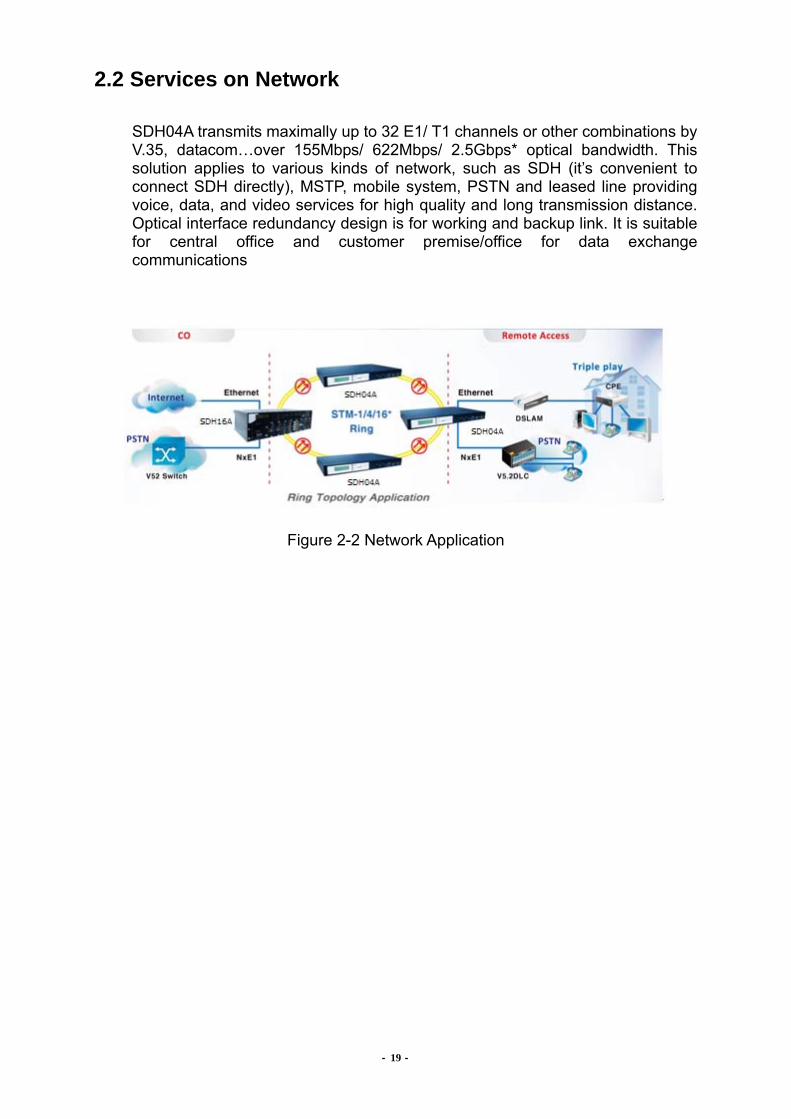
SDH04A transmits maximally up to 32 E1/ T1 channels or other combinations by V.35, datacom…over 155Mbps/ 622Mbps/ 2.5Gbps* optical bandwidth. This solution applies to various kinds of network, such as SDH (it’s convenient to connect SDH directly), MSTP, mobile system, PSTN and leased line providing voice, data, and video services for high quality and long transmission distance. Optical interface redundancy design is for working and backup link. It is suitable for central office and customer premise/office for data exchange communications
Figure 2-2 Network Application

- 20 -
2.3 EoS for E-LAN With EoS technology, Ethernet communication can be applied between all nodes for E-LAN application. As the figure shown, The E-LAN services are fully meshed.
Figure 2-3 Fully Meshed E-LAN Service
- 21 -
Chapter 3. Panel Description
This chapter gives the details about front and rear panels of SDH04A main system and panels of each module.
3.1 SDH04A Front Panel Overview
Figure 3-1 SDH04A Front Panel Overview
3.1.1 Tributary Status on LED
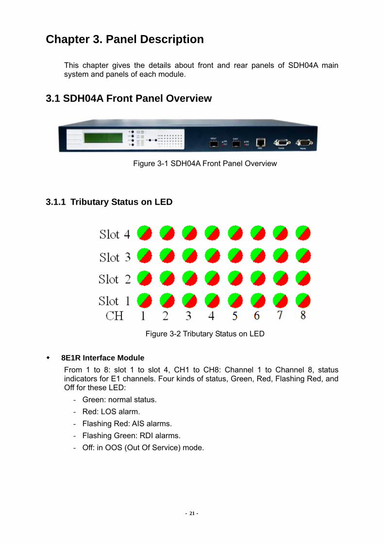
Figure 3-2 Tributary Status on LED
8E1R Interface Module
From 1 to 8: slot 1 to slot 4, CH1 to CH8: Channel 1 to Channel 8, status indicators for E1 channels. Four kinds of status, Green, Red, Flashing Red, and Off for these LED:
- Green: normal status. - Red: LOS alarm. - Flashing Red: AIS alarms. - Flashing Green: RDI alarms. - Off: in OOS (Out Of Service) mode.

SDH04A User Manual
- 22 -
QE1 Interface Module From 1 to 4: slot 1 to slot 4, CH1 to CH4: Channel 1 to Channel 4, status indicators for E1 channels. Four kinds of status, Green, Red, Flashing Red, and Off for these LED:
- Green: normal status. - Red: LOS / LOF alarms. - Flashing Red: AIS alarms. - Flashing Green: RDI alarms. - Off: in OOS (Out Of Service) mode.
8ET Interface Module
From 1 to 8: slot 1 to slot 4, CH1 to CH8: Channel 1 to Channel 8, status indicators for E1/T1 channels. Four kinds of status, Green, Red, Flashing Red, and Off for these LED:
- Green: normal status. - Red: LOS / LOF alarms. - Flashing Red: AIS alarms. - Flashing Green: RDI alarms. - Off: in OOS (Out Of Service) mode.
QV35 Interface Module
From 1 to 4: slot 1 to slot 4, CH1 to CH4: Channel 1 to Channel 4, status indicators for V.35 channels. Three kinds of status, Green, Red, and Off for these LED:
- Green: normal status. - Red: LOS alarm. - Off: in OOS (Out Of Service) mode.
ET3 Interface Module
From 1 to 4: slot 1 to slot 4, status indicators for E3/DS3 channel. Four kinds of status, Green, Red, Flashing Red, and Off for these LED:
- Green: normal status. - Red: LOS / LOF alarms. - Flashing Red: AIS alarms. - Flashing Green: RDI alarms. - Off: in OOS (Out Of Service) mode.

SDH04A User Manual
- 23 -
GBE Interface Module From 1 to 4: slot 1 to slot 4, CH1 to CH4: Channel 1 to Channel 4, status indicators for Ethernet channels. Three kinds of status, Green, Red, and Off for these LED:
- Green: Link Up on corresponding Ethernet port. - Red: Link Down on corresponding Ethernet port. - Off: in OOS (Out Of Service) mode.
- 24 -
3.1.2 Alarm Indication on LED
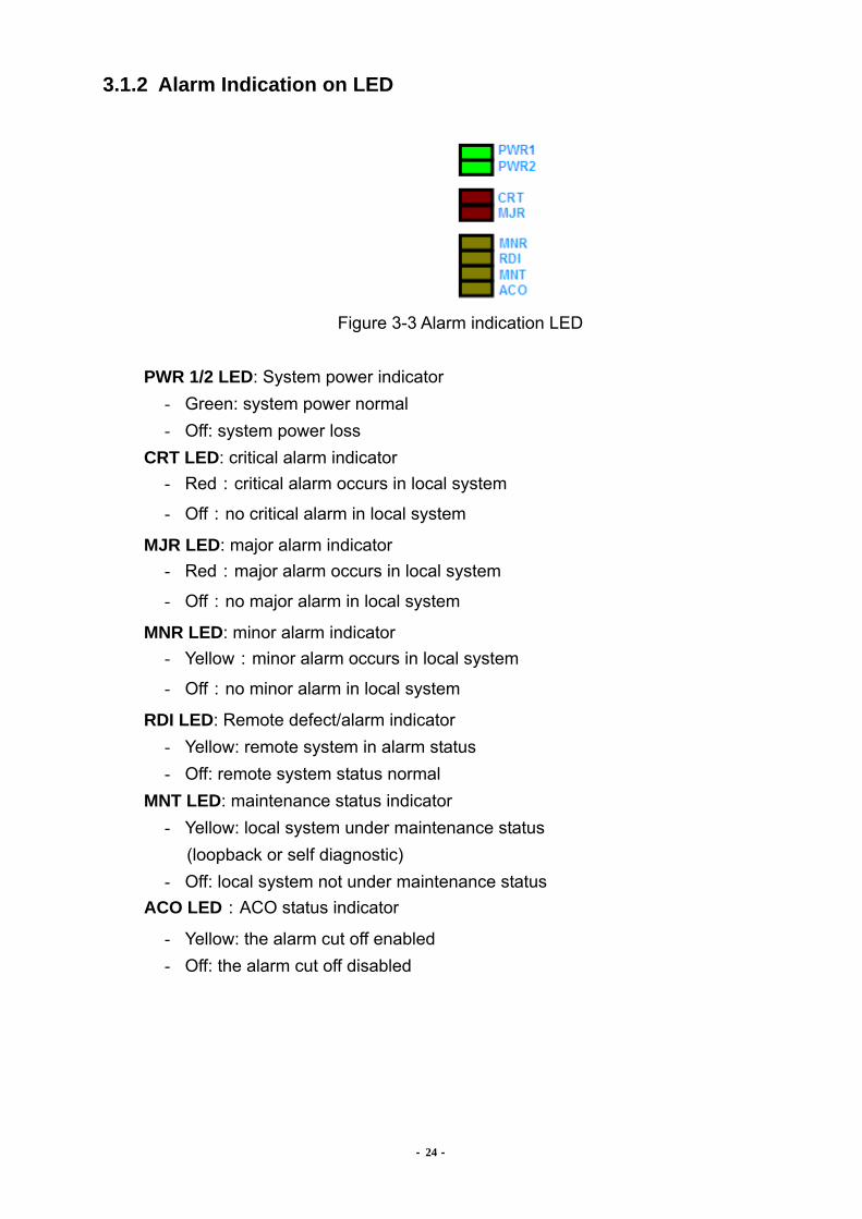
Figure 3-3 Alarm indication LED
PWR 1/2 LED: System power indicator
- Green: system power normal - Off: system power loss
CRT LED: critical alarm indicator - Red:critical alarm occurs in local system
- Off:no critical alarm in local system
MJR LED: major alarm indicator - Red:major alarm occurs in local system
- Off:no major alarm in local system
MNR LED: minor alarm indicator - Yellow:minor alarm occurs in local system
- Off:no minor alarm in local system
RDI LED: Remote defect/alarm indicator - Yellow: remote system in alarm status - Off: remote system status normal
MNT LED: maintenance status indicator - Yellow: local system under maintenance status (loopback or self diagnostic) - Off: local system not under maintenance status
ACO LED:ACO status indicator
- Yellow: the alarm cut off enabled - Off: the alarm cut off disabled

- 25 -
3.1.3 RJ-45 Pin Assignment for NMS Port
This is the NMS network management system interface for Web Server management by 10/100M Ethernet. The selection of 10 or 100M data rate is auto negotiable. LAN interface uses standard RJ-45 female connector. The pin assignment follows MDI standard as below.
Pin Number Function 1 Tx+ 2 Tx- 3 Rx+ 4 NC 5 NC 6 Rx- 7 NC 8 NC
Table 3-1 RJ-45 pin assignments
3.1.4 Console Craft Console craft provides menu-driven for user to manage the equipment. It is 9 pins, D-sub, female connector. Please refer to Chapter 6 and Appendix B for details. The pin assignment is as below.
Figure 3-4 Console pin assignment (DB9)
Pin Number Function 1 NC 2 Tx 3 Rx 4 NC 5 GND 6 NC 7 NC 8 NC
Table 3-2 CONSOLE pin assignment (DB9)
- 26 -
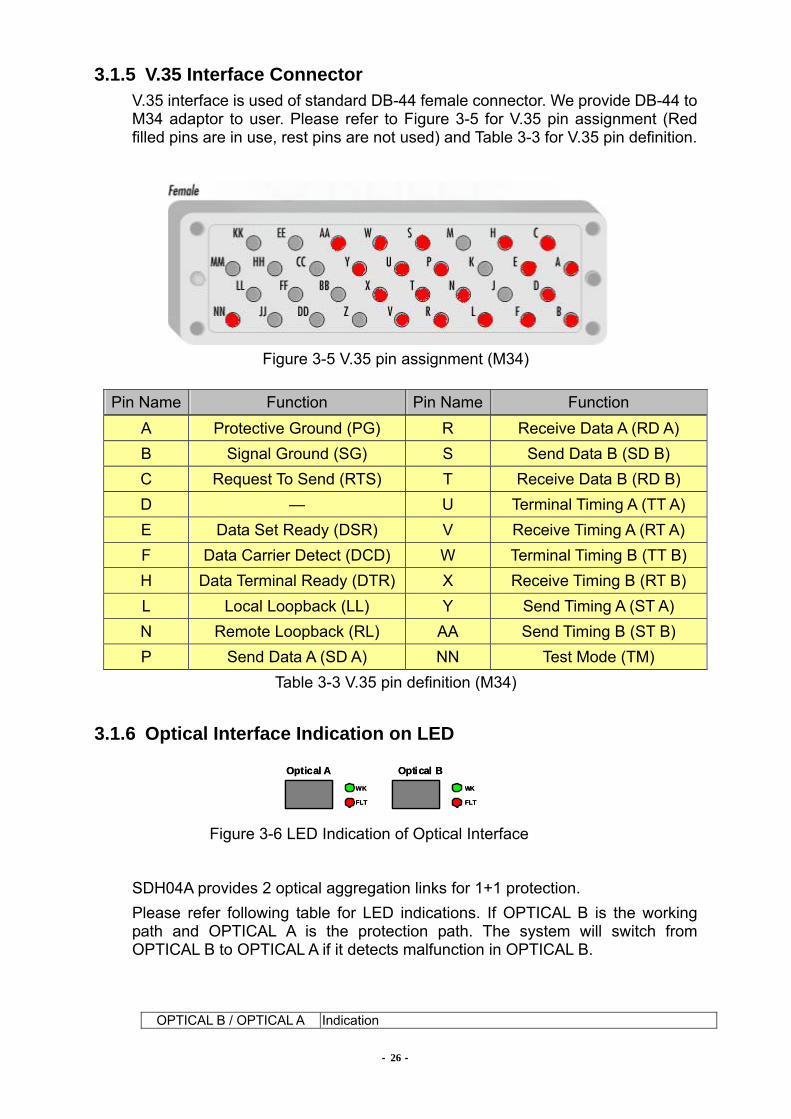
3.1.5 V.35 Interface Connector V.35 interface is used of standard DB-44 female connector. We provide DB-44 to M34 adaptor to user. Please refer to Figure 3-5 for V.35 pin assignment (Red filled pins are in use, rest pins are not used) and Table 3-3 for V.35 pin definition.
Figure 3-5 V.35 pin assignment (M34)
Pin Name Function Pin Name Function A Protective Ground (PG) R Receive Data A (RD A) B Signal Ground (SG) S Send Data B (SD B) C Request To Send (RTS) T Receive Data B (RD B) D — U Terminal Timing A (TT A) E Data Set Ready (DSR) V Receive Timing A (RT A) F Data Carrier Detect (DCD) W Terminal Timing B (TT B) H Data Terminal Ready (DTR) X Receive Timing B (RT B) L Local Loopback (LL) Y Send Timing A (ST A) N Remote Loopback (RL) AA Send Timing B (ST B) P Send Data A (SD A) NN Test Mode (TM)
Table 3-3 V.35 pin definition (M34)
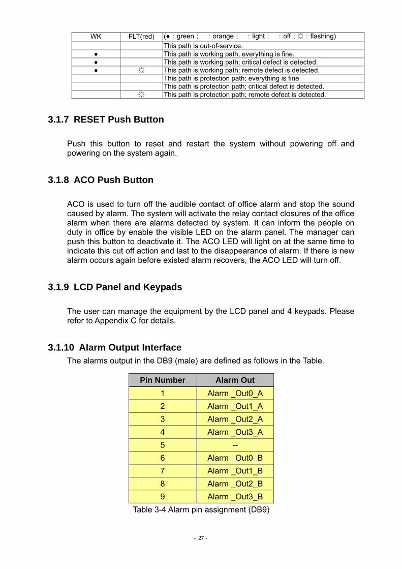
3.1.6 Optical Interface Indication on LED
Figure 3-6 LED Indication of Optical Interface
SDH04A provides 2 optical aggregation links for 1+1 protection. Please refer following table for LED indications. If OPTICAL B is the working path and OPTICAL A is the protection path. The system will switch from OPTICAL B to OPTICAL A if it detects malfunction in OPTICAL B.
OPTICAL B / OPTICAL A Indication
WK
FLT
WK
FLT
Optical A Optical BWK
FLT
WK
FLT
Optical A Optical B
- 27 -
WK FLT(red) (:green;:orange;:light;:off;:flashing) This path is out-of-service. This path is working path; everything is fine. This path is working path; critical defect is detected. This path is working path; remote defect is detected. This path is protection path; everything is fine. This path is protection path; critical defect is detected. This path is protection path; remote defect is detected.
3.1.7 RESET Push Button
Push this button to reset and restart the system without powering off and powering on the system again.
3.1.8 ACO Push Button
ACO is used to turn off the audible contact of office alarm and stop the sound caused by alarm. The system will activate the relay contact closures of the office alarm when there are alarms detected by system. It can inform the people on duty in office by enable the visible LED on the alarm panel. The manager can push this button to deactivate it. The ACO LED will light on at the same time to indicate this cut off action and last to the disappearance of alarm. If there is new alarm occurs again before existed alarm recovers, the ACO LED will turn off.
3.1.9 LCD Panel and Keypads
The user can manage the equipment by the LCD panel and 4 keypads. Please refer to Appendix C for details.
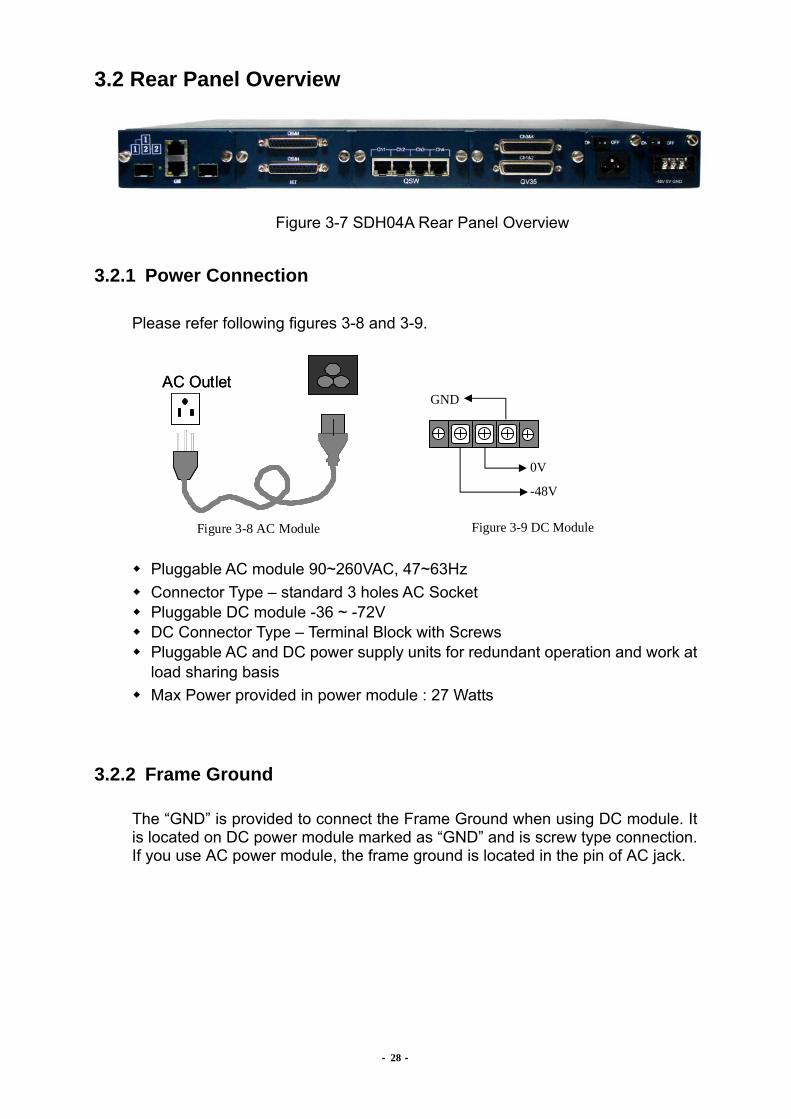
3.1.10 Alarm Output Interface The alarms output in the DB9 (male) are defined as follows in the Table.
Pin Number Alarm Out 1 Alarm _Out0_A 2 Alarm _Out1_A 3 Alarm _Out2_A 4 Alarm _Out3_A 5 -- 6 Alarm _Out0_B 7 Alarm _Out1_B 8 Alarm _Out2_B 9 Alarm _Out3_B
Table 3-4 Alarm pin assignment (DB9)
- 28 -
3.2 Rear Panel Overview
Figure 3-7 SDH04A Rear Panel Overview
3.2.1 Power Connection
Please refer following figures 3-8 and 3-9.
Pluggable AC module 90~260VAC, 47~63Hz Connector Type – standard 3 holes AC Socket Pluggable DC module -36 ~ -72V DC Connector Type – Terminal Block with Screws Pluggable AC and DC power supply units for redundant operation and work at
load sharing basis Max Power provided in power module : 27 Watts
3.2.2 Frame Ground
The “GND” is provided to connect the Frame Ground when using DC module. It is located on DC power module marked as “GND” and is screw type connection. If you use AC power module, the frame ground is located in the pin of AC jack.
Figure 3-9 DC Module
0V
-48V
GNDAC OutletAC Outlet
Figure 3-8 AC Module
SDH04A User Manual
- 29 -
3.2.3 Electricity Power Switch
Figure 3-10 Electricity power switch
On/Off button is to turn on/off both AC/DC powers.
3.2.4 Tributary Slot
SDH04A provides 4 tributary slots in the rear panel for various interfaces and services according to the configuration.

- 30 -
Chapter 4. Installation
This chapter will describe the procedures to install and information users need to know.
4.1 Install Equipment and Start the System
1. Mount the equipment on rack or place on table 2. Make sure the power switch is off 3. “GND” is provided to connect the Frame Ground and also it is for lightening
protection. It is located on DC power module marked as “GND” and is a screw type connection. Before installation, please make sure you connect the GND to the frame ground.
4.1.1 Install AC Power
1. Mount the equipment on rack or place on table 2. Plug in AC power supply unit 3. Turn the power switch off 4. Connect AC power cord to AC power supply (Before installation, please make
sure you connect the GND to the frame ground.) 5. Turn on the switch
4.1.2 Install DC Power
1. Set and check the power output of DC power supply to proper range 2. Plug in DC power supply unit 3. Turn off the power switch before connecting power cable. 4. Connect power cables. Please check the poles of positive and negative. 5. Connect Frame Ground. (It is located on DC power module marked as “GND”
and is a screw type connection. Before installation, please make sure you connect the GND to the frame ground.)
6. Turn on the power supply 7. Check the power and poles of power. Then turn on the switch of equipment.
4.1.3 Start the System
After the electricity power applied, the system will start to initialize and set up. The LED indicators on the panel are flashing while initializing and stop flashing after setup is done. The setup conditions are in default mode and the transmission is in IS mode at the first starting up after shipment.
- 31 -
4.2 Install Tributary Modules
Because of the module design, the user can insert modules one by one according to the practical needs. The user can also equip with different service modules by applications, such as E1/T1/E3/T3 interfaces and/or data services like Ethernet. Each channel can be configured or set independently.
4.3 Management Interface
4.3.1 Install Console Interface
The user can connect the Console port to VT-100 compatible terminal or PC/notebook with terminal program by RS-232 cable. It can connect to terminal or PC directly without crossover. Please refer to chapter 3.1.4 for RS-232 port pin definition and chapter 7.3 for parameters and settings.
4.3.2 Install NMS Interface
The NMS port is RJ-45 Ethernet port with pin definition as MDI. Please refer to chapter 3.1.3. After connecting to management centre through LAN/DCN or Internet and provisioning, the NMS can manage SDH04A centrally. The cable for Ethernet is UTP-5 or better and the distance and length should not over 100 meters to guarantee the communication quality.
4.4 Connect Cables
4.4.1 Connect Fiber Cable
The fibre cable/patch cord between SDH04A and the ODF should be right type of connectors and suitable length. Please tight the connector normally and do not bend the fibre too much to damage the fibre while connecting. Be careful about the laser light and do not star at the light beam. It may be harmful to your eyes.
4.4.2 Connect E-X/DS-X Cable
(1) BNC type The connection type of 4E1B/ET3 is BNC. Upper one is data output port and lower one is data input port. Make sure that the connection is correct. If E1 connection is RJ-48, there is a cable to convert RJ-48 to BNC.

- 32 -
(2) Wire-wrap type 8ET connection is D25 convert to wire-wrap type (with one adaptor). There are 6 pins in one channel: OP/ON (Output Positive/Output Negative) for output, IP/IN (Input Positive/Input Negative) for input and 2 FG (Frame Ground). Make sure that the connection is correct.
4.4.3 GBE Interface Module
The user can connect the CAT-5e/CAT-6 Cable to RJ-45 connector or use SFP module with LC connector to SFP type connector. Please tight the connector normally.
4.4.4 QV35 Interface Module
The user can connect DB-44 part of DB-44 to M34 convert cable to QV35 card and use other part (i.e.M34 connector) as normal V.35 connecter.
4.5 Install Office Alarm
By the office alarm ports as described in chapter 3.1.9, SDH04A can connect alarms to the central alarm panel in office to inform the manager on duty by visible indicators when there is alarm occurs. The office alarm input range limitations are as below.
- Maximum voltage: 60V - Maximum current: 100mA (continuous) / 350mA (peak to peak)

- 33 -
Chapter 5. Module Description
SDH04A is equipped with many slots for user different demands in addition to main board. Four tributary slots provide flexible configurations and full services. The modules are described as below.
5.1 AC/DC Pluggable Power Module
SDH04A provides pluggable AC/DC power supply units for redundant operation and work at load sharing basis. The power supplied by:
AC : 90~260Vac, 47~63Hz DC : -36 ~ -72V
5.2 4E1B: 4-channel E1 Interface Module
SDH04A User Manual
- 34 -
Connector type: BNC Impedance: 75Ω±5% There are E1 (2.048 Mbps) transmission module which provides 4-channel to transmit transparently. The E1 interfaces meet the ITU-T (G.703) and ANSI standards. Each can be configured as E1 by management interface. Meanwhile, the parameter settings, such as line code (HDB3/AMI), are field selectable. These functions can be provisioned via system Console, LCD or Web Server, when an E1 channel is being provisioned the other channels should not fail during the process The E1 interfaces are individually terminated.
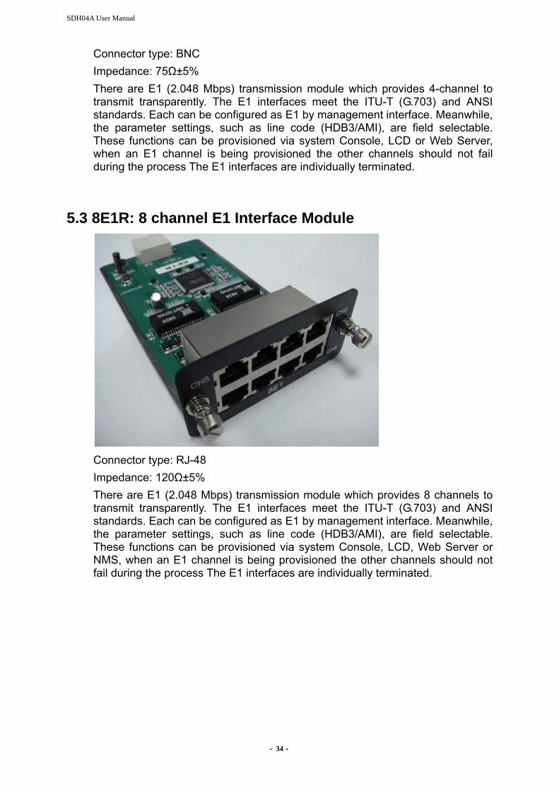
5.3 8E1R: 8 channel E1 Interface Module
Connector type: RJ-48 Impedance: 120Ω±5% There are E1 (2.048 Mbps) transmission module which provides 8 channels to transmit transparently. The E1 interfaces meet the ITU-T (G.703) and ANSI standards. Each can be configured as E1 by management interface. Meanwhile, the parameter settings, such as line code (HDB3/AMI), are field selectable. These functions can be provisioned via system Console, LCD, Web Server or NMS, when an E1 channel is being provisioned the other channels should not fail during the process The E1 interfaces are individually terminated.
- 35 -
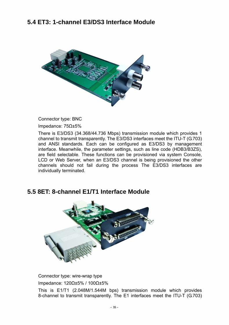
5.4 ET3: 1-channel E3/DS3 Interface Module
Connector type: BNC Impedance: 75Ω±5% There is E3/DS3 (34.368/44.736 Mbps) transmission module which provides 1 channel to transmit transparently. The E3/DS3 interfaces meet the ITU-T (G.703) and ANSI standards. Each can be configured as E3/DS3 by management interface. Meanwhile, the parameter settings, such as line code (HDB3/B3ZS), are field selectable. These functions can be provisioned via system Console, LCD or Web Server, when an E3/DS3 channel is being provisioned the other channels should not fail during the process The E3/DS3 interfaces are individually terminated.
5.5 8ET: 8-channel E1/T1 Interface Module
Connector type: wire-wrap type Impedance: 120Ω±5% / 100Ω±5% This is E1/T1 (2.048M/1.544M bps) transmission module which provides 8-channel to transmit transparently. The E1 interfaces meet the ITU-T (G.703)

- 36 -
and ANSI standards. The T1 interfaces meet ANSI T1.102 standards. Each can be configured as E1 or T1 by management interface. Meanwhile, the parameter settings, such as line code or framing format, are field selectable. These functions can be provisioned via system Console, LCD or Web Server, when an E1/T1 channel is being provisioned the other channels should not fail during the process The E1/T1 interfaces are individually terminated.
5.6 QV35: 4-channel V.35 Interface Module
QV35 provides up to 4 channels of Nx64Kbps (N=1 to 32) transmission module. The V.35 interface meets ITU-T V.35 standard. User can assign the bandwidth and clock source by management interface. The DTR/RDL/LLB signals can be ignored because of some V.35 DTE does not provide these signals currently.
5.7 GBE: 4-port 10/100/1000M Ethernet Interface Module
GBE provides up to 4 channels of 10/100/1000M Ethernet transmission module. Users can choose Electrical or Optical type service. The user can assign the bandwidth in high-speed optical signal for Ethernet data communicating between two ends by the practical needs. The basic incremental unit of the bandwidth is one standard VC-3 (about 48.384 Mbps).

- 37 -
Chapter 6. System Operations 6.1 Start and Reset System
6.1.1 Power Supply
SDH04A can be applied by 110/220 AC or -48V DC power. System works stable with single power (please also make sure the current in your environment is stable). When both AC and DC powers are applied, the AC will work independently. Initially, the system will start working by AC power source and then switch to DC power when the AC power is down or the voltage or current are not stable. When the system is switching to DC from AC, there is no interruption in the working system and the traffic won’t be influenced. Either AC or DC can be powered off manually by the switches in machine’s back panel. After power is applied properly, SDH04A starts the POST (Power-On Self Test) and then initializes the system by the data in the non-volatile backup memory after POST passed. AC power after completion of lightning surge immunity test, a temporary degradation of transmission performance or temporary loss of function might be acceptable, but the equipment and protection device must be self-recoverable. To fulfil surge protection in easy-installation manner, the SDH04A will incorporate with chassis grounding mechanism on the exterior of device.
6.1.2 System Reset
The user can reset SDH04A by many ways according to different conditions. 1. Push button reset: This will restart the microprocessor and clear the PM and
alarm records. There is no change about system settings and no interruption to the traffics under working.
2. Software reset by management systems: This will restart the microprocessor and clear the PM and alarm records. There is no change about system settings and no interruption to the traffics under working.
3. Hardware reset by management systems: This will restart the microprocessor and clear the PM and alarm records. There is also no change about system settings. But the traffics will be interrupted until the hardware recovered.
4. Reset back to previous version by management systems: After command operated, the software will back to the previous version in case that current one is damaged.
SDH04A User Manual
- 38 -
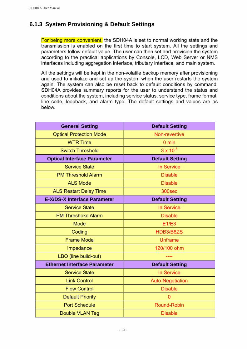
6.1.3 System Provisioning & Default Settings
For being more convenient, the SDH04A is set to normal working state and the transmission is enabled on the first time to start system. All the settings and parameters follow default value. The user can then set and provision the system according to the practical applications by Console, LCD, Web Server or NMS interfaces including aggregation interface, tributary interface, and main system.
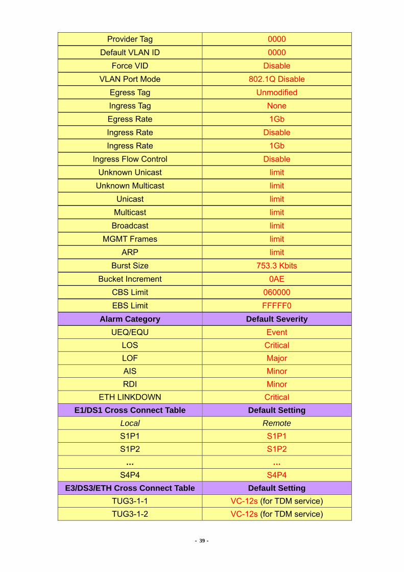
All the settings will be kept in the non-volatile backup memory after provisioning and used to initialize and set up the system when the user restarts the system again. The system can also be reset back to default conditions by command. SDH04A provides summary reports for the user to understand the status and conditions about the system, including service status, service type, frame format, line code, loopback, and alarm type. The default settings and values are as below.
General Setting Default Setting Optical Protection Mode Non-revertive
WTR Time 0 min Switch Threshold 3 x 10⁻⁵
Optical Interface Parameter Default Setting Service State In Service
PM Threshold Alarm Disable ALS Mode Disable
ALS Restart Delay Time 300sec E-X/DS-X Interface Parameter Default Setting
Service State In Service PM Threshokd Alarm Disable
Mode E1/E3 Coding HDB3/B8ZS
Frame Mode Unframe Impedance 120/100 ohm
LBO (line build-out) ---- Ethernet Interface Parameter Default Setting
Service State In Service Link Control Auto-Negotiation Flow Control Disable
Default Priority 0 Port Schedule Round-Robin
Double VLAN Tag Disable
- 39 -
Provider Tag 0000 Default VLAN ID 0000
Force VID Disable VLAN Port Mode 802.1Q Disable
Egress Tag Unmodified Ingress Tag None Egress Rate 1Gb Ingress Rate Disable Ingress Rate 1Gb
Ingress Flow Control Disable Unknown Unicast limit
Unknown Multicast limit Unicast limit
Multicast limit Broadcast limit
MGMT Frames limit ARP limit
Burst Size 753.3 Kbits Bucket Increment 0AE
CBS Limit 060000 EBS Limit FFFFF0
Alarm Category Default Severity UEQ/EQU Event
LOS Critical LOF Major AIS Minor RDI Minor
ETH LINKDOWN Critical E1/DS1 Cross Connect Table Default Setting
Local Remote S1P1 S1P1 S1P2 S1P2
… … S4P4 S4P4
E3/DS3/ETH Cross Connect Table Default Setting TUG3-1-1 VC-12s (for TDM service) TUG3-1-2 VC-12s (for TDM service)
- 40 -
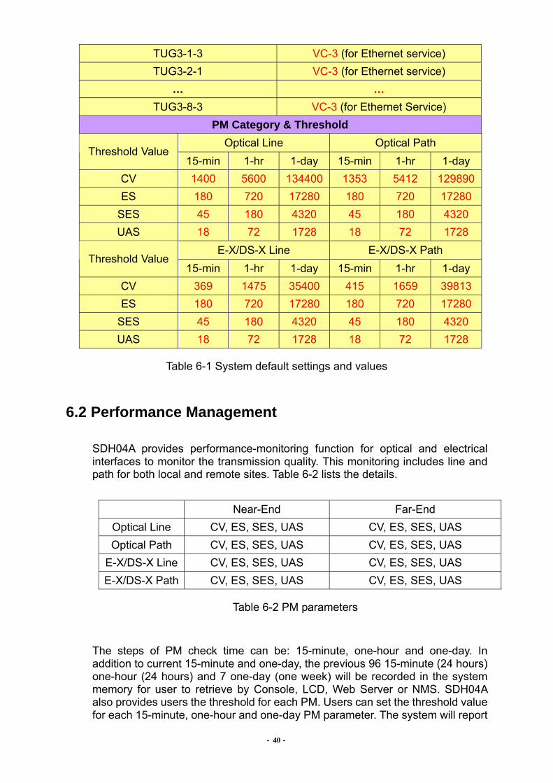
TUG3-1-3 VC-3 (for Ethernet service) TUG3-2-1 VC-3 (for Ethernet service)
… … TUG3-8-3 VC-3 (for Ethernet Service)
PM Category & Threshold Optical Line Optical Path
Threshold Value 15-min 1-hr 1-day 15-min 1-hr 1-day
CV 1400 5600 134400 1353 5412 129890 ES 180 720 17280 180 720 17280
SES 45 180 4320 45 180 4320 UAS 18 72 1728 18 72 1728
E-X/DS-X Line E-X/DS-X Path Threshold Value
15-min 1-hr 1-day 15-min 1-hr 1-day CV 369 1475 35400 415 1659 39813 ES 180 720 17280 180 720 17280
SES 45 180 4320 45 180 4320 UAS 18 72 1728 18 72 1728
Table 6-1 System default settings and values
6.2 Performance Management SDH04A provides performance-monitoring function for optical and electrical interfaces to monitor the transmission quality. This monitoring includes line and path for both local and remote sites. Table 6-2 lists the details.
Near-End Far-End Optical Line CV, ES, SES, UAS CV, ES, SES, UAS Optical Path CV, ES, SES, UAS CV, ES, SES, UAS
E-X/DS-X Line CV, ES, SES, UAS CV, ES, SES, UAS E-X/DS-X Path CV, ES, SES, UAS CV, ES, SES, UAS
Table 6-2 PM parameters
The steps of PM check time can be: 15-minute, one-hour and one-day. In addition to current 15-minute and one-day, the previous 96 15-minute (24 hours) one-hour (24 hours) and 7 one-day (one week) will be recorded in the system memory for user to retrieve by Console, LCD, Web Server or NMS. SDH04A also provides users the threshold for each PM. Users can set the threshold value for each 15-minute, one-hour and one-day PM parameter. The system will report

- 41 -
TCA (Threshold Crossing Alarm) to management interfaces when the PM value exceeds the threshold.
6.3 Optical Interface Operation SDH04A provides 1+1 auto protection switch for optical link by the optical modules equipped in the system. The receiving signal of aggregate will come from the working fibre link, and the other link will be the standby for protection purpose. When the working line detects LOS, LOF, or AIS, the system will switch the fibre line from working to the standby. The switching time is less than 30ms. The system will switch the module from working module to the protection one when the working module fails. The optical protection mechanism is well designed to prevent from instability between working and protection optical lines. There are two kinds of APS function: Revertible and Non-revertible.。Under non-revertible mode, the optical line will not be switched back to the originated one even it recovers to normal working. When it is under revertible mode, the system will define the primary slot/module to be working line. After APS implemented, the optical line will be switched to protection line. If the working line is recovered, the fibre line will be switched back to the primary/working line again. The protection switch can be implemented by management systems. Users can operate the command manually through Console, LCD, Web Server or NMS. There are two ways for the manual switch: Normal and Lock. In normal mode, the switch will be implemented only if the protection line is in normal status. But in the lock mode, users can make the switch no matter the protection line is good or bad. SDH04A will generate AIS signal to the output of all E1/T1 channels during the optical lines fail. SDH04A provides ALS (Auto Laser Shut down) function. The laser transmitter on local site will shut down the power output when remote site laser cannot receive optical signal properly. Then the laser output will be turned on periodically to send out signal for testing whether the remote site can receive normally. The laser will work normally again after remote site recovers receiving. The user can also test and start laser manually. The parameters of optical module are in the next table.
Parameter Settings WTR Time 0~15min ALS Mode Enable/Disable Delay Time 60~300sec
Protection Mode Revertive/Non-revertive
Table 6-3 Optical module parameters
*Warning* Keep your eyes away from the laser or fibre connector when the equipment is in power on status in case of any damage.
- 42 -
6.4 Alarm Management
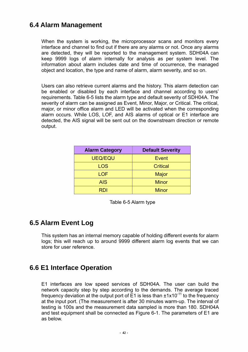
When the system is working, the microprocessor scans and monitors every interface and channel to find out if there are any alarms or not. Once any alarms are detected, they will be reported to the management system. SDH04A can keep 9999 logs of alarm internally for analysis as per system level. The information about alarm includes date and time of occurrence, the managed object and location, the type and name of alarm, alarm severity, and so on. Users can also retrieve current alarms and the history. This alarm detection can be enabled or disabled by each interface and channel according to users’ requirements. Table 6-5 lists the alarm type and default severity of SDH04A. The severity of alarm can be assigned as Event, Minor, Major, or Critical. The critical, major, or minor office alarm and LED will be activated when the corresponding alarm occurs. While LOS, LOF, and AIS alarms of optical or E1 interface are detected, the AIS signal will be sent out on the downstream direction or remote output.
Alarm Category Default Severity UEQ/EQU Event
LOS Critical LOF Major AIS Minor RDI Minor
Table 6-5 Alarm type
6.5 Alarm Event Log
This system has an internal memory capable of holding different events for alarm logs; this will reach up to around 9999 different alarm log events that we can store for user reference.
6.6 E1 Interface Operation
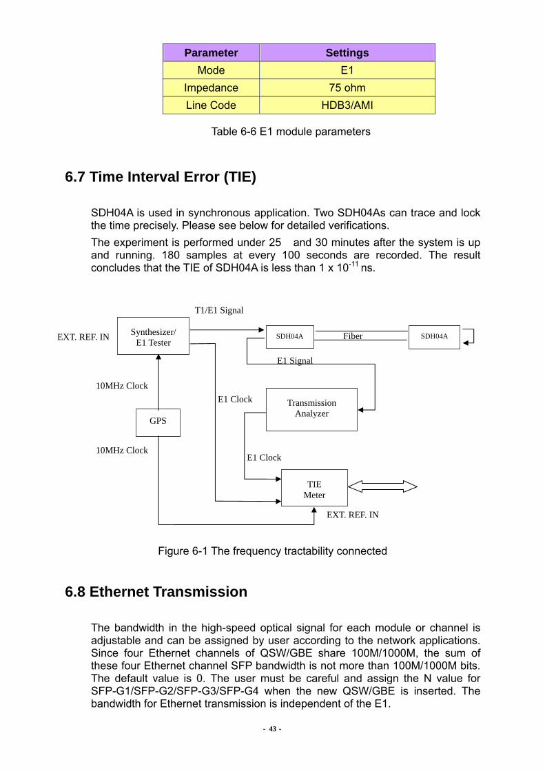
E1 interfaces are low speed services of SDH04A. The user can build the network capacity step by step according to the demands. The average traced frequency deviation at the output port of E1 is less than ±1x10-11 to the frequency at the input port. (The measurement is after 30 minutes warm-up. The interval of testing is 100s and the measurement data sampled is more than 180. SDH04A and test equipment shall be connected as Figure 6-1. The parameters of E1 are as below.
- 43 -
Parameter Settings Mode E1
Impedance 75 ohm Line Code HDB3/AMI
Table 6-6 E1 module parameters
6.7 Time Interval Error (TIE)
SDH04A is used in synchronous application. Two SDH04As can trace and lock the time precisely. Please see below for detailed verifications. The experiment is performed under 25 and 30 minutes after the system is up and running. 180 samples at every 100 seconds are recorded. The result concludes that the TIE of SDH04A is less than 1 x 10-11 ns.
Figure 6-1 The frequency tractability connected
6.8 Ethernet Transmission
The bandwidth in the high-speed optical signal for each module or channel is adjustable and can be assigned by user according to the network applications. Since four Ethernet channels of QSW/GBE share 100M/1000M, the sum of these four Ethernet channel SFP bandwidth is not more than 100M/1000M bits. The default value is 0. The user must be careful and assign the N value for SFP-G1/SFP-G2/SFP-G3/SFP-G4 when the new QSW/GBE is inserted. The bandwidth for Ethernet transmission is independent of the E1.
Synthesizer/ E1 Tester
SDH04A SDH04A
Transmission Analyzer
TIE Meter
GPS
T1/E1 Signal
Fiber
E1 Signal
E1 Clock 10MHz Clock
E1 Clock
EXT. REF. IN
EXT. REF. IN
10MHz Clock
- 44 -
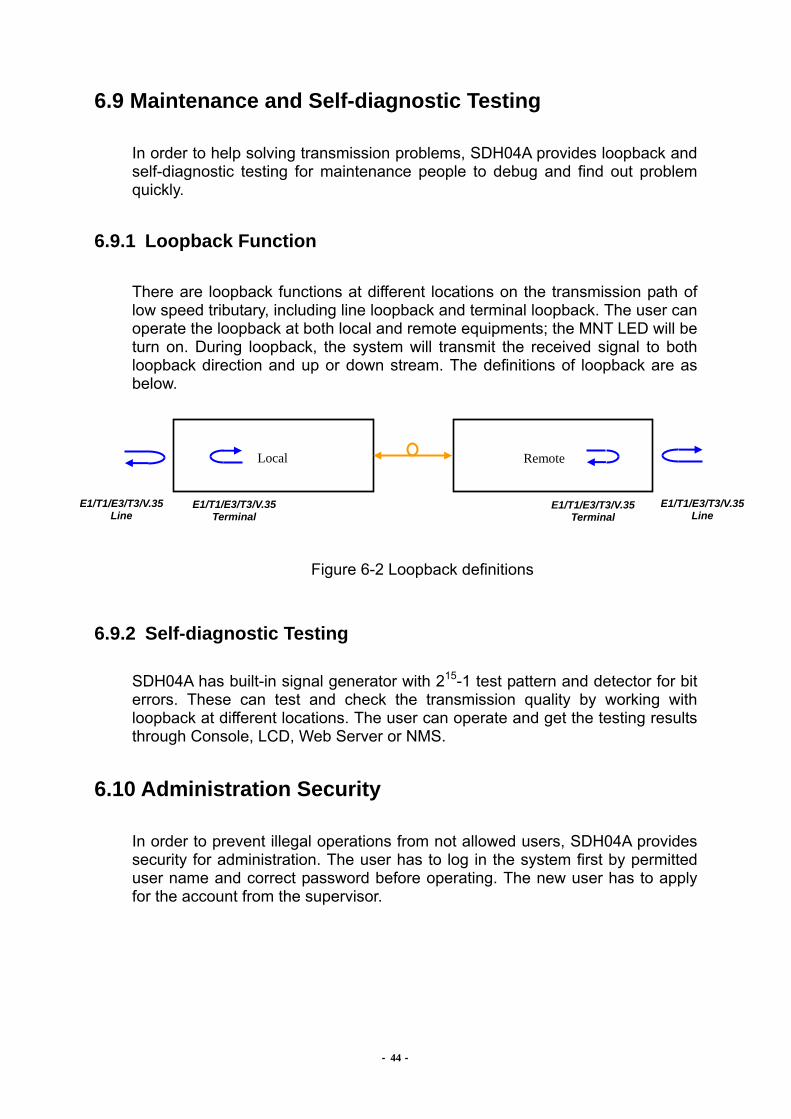
6.9 Maintenance and Self-diagnostic Testing
In order to help solving transmission problems, SDH04A provides loopback and self-diagnostic testing for maintenance people to debug and find out problem quickly.
6.9.1 Loopback Function
There are loopback functions at different locations on the transmission path of low speed tributary, including line loopback and terminal loopback. The user can operate the loopback at both local and remote equipments; the MNT LED will be turn on. During loopback, the system will transmit the received signal to both loopback direction and up or down stream. The definitions of loopback are as below.
Figure 6-2 Loopback definitions
6.9.2 Self-diagnostic Testing
SDH04A has built-in signal generator with 215-1 test pattern and detector for bit errors. These can test and check the transmission quality by working with loopback at different locations. The user can operate and get the testing results through Console, LCD, Web Server or NMS.
6.10 Administration Security
In order to prevent illegal operations from not allowed users, SDH04A provides security for administration. The user has to log in the system first by permitted user name and correct password before operating. The new user has to apply for the account from the supervisor.
Local
Remote
E1/T1/E3/T3/V.35 Line
E1/T1/E3/T3/V.35 Terminal
E1/T1/E3/T3/V.35 Terminal
E1/T1/E3/T3/V.35 Line

SDH04A User Manual
- 45 -
6.11 System Management
In order to manage the equipment, user can retrieve the system information and set the date and time of the system by management interfaces. In addition, the manager can set the IP address of NMS, trap IP address of the alarm report, and the community of Get and Set for SNMP to build the network management system.

- 46 -
Chapter 7. Network Management
SDH04A provides Console, LCD, Web Server and NMS interfaces for network management. In the field support, LCD is a convenient way to operate and debug. But it is limited by the display method. The Console and Web Server can display many messages on the same frame. They are good and quick for manager to manage after connecting terminal or PC/notebook with terminal program. The NMS is a standard management interface with Ethernet physical layer and SNMP protocol. All these three interfaces provide full functions of OAM&P. The management systems are single-ended and the user can manage both local and remote systems at one side through the DCC.
7.1 NMS Interface and SNMP
SDH04A supports SNMP V2c, and follows RFC1406, RFC 2495, RFC 2493 (PM) and self defined parameters for SNMP MIB which comply with RFC1155, RFC2578 and RFC1212. The protocol layers of SDH04A’s NMS interfaces are Ethernet, IP, UDP, and SNMP. The user can manage the equipment by CTC Union.’s window based management software. Its user operation interface is GUI (Graphical User Interface), which is friendly and easy to use. The user can also use other SNMP management software to manage the remote nodes, or develop its own management and integrate with other systems by the SNMP MIB provided by CTC Union., to manage the remote nodes. For details please refer to CTC Union. GMS User Manual
Figure 7-1 SNMP NMS structure
- 47 -
7.2 NMS Functions
SDH04A provides full OAM&P (Operation, Administration, Maintenance, and Provisioning) functions. The management functions are as below.
Configuration Management (CM) Fault Management (FM) Performance Monitoring (PM) Security Management (SM) Operation System Setup
For details please refer to CTC Union. GMS User Manual
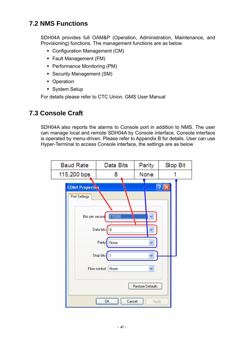
7.3 Console Craft
SDH04A also reports the alarms to Console port in addition to NMS. The user can manage local and remote SDH04A by Console interface. Console interface is operated by menu-driven. Please refer to Appendix B for details. User can use Hyper-Terminal to access Console interface, the settings are as below
- 48 -
7.4 LCD Interface
LCD is a convenient method for maintenance in field. It uses hierarchy menu and keypads to select and execute the commands. Please refer to Appendix C for details.
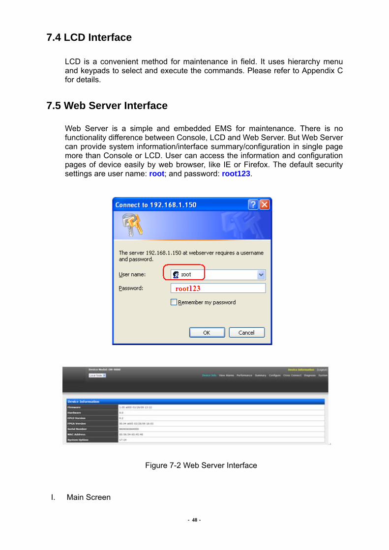
7.5 Web Server Interface
Web Server is a simple and embedded EMS for maintenance. There is no functionality difference between Console, LCD and Web Server. But Web Server can provide system information/interface summary/configuration in single page more than Console or LCD. User can access the information and configuration pages of device easily by web browser, like IE or Firefox. The default security settings are user name: root; and password: root123.
Figure 7-2 Web Server Interface
I. Main Screen
- 49 -
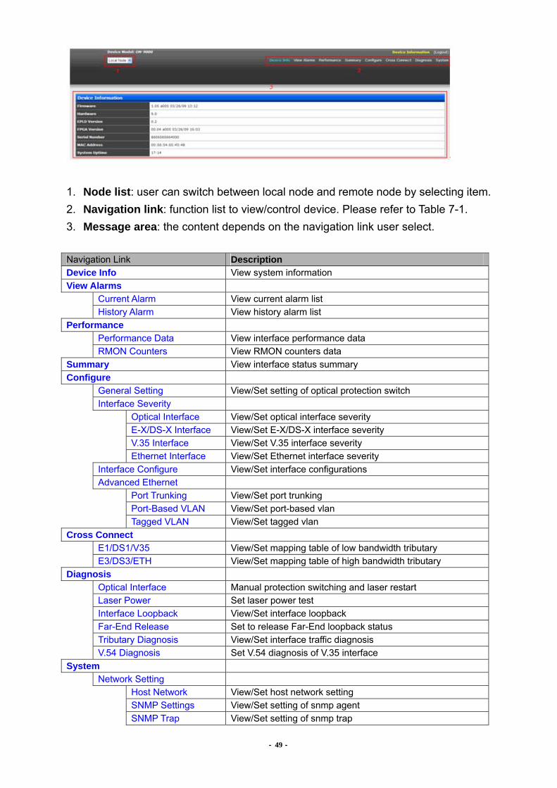
1. Node list: user can switch between local node and remote node by selecting item. 2. Navigation link: function list to view/control device. Please refer to Table 7-1. 3. Message area: the content depends on the navigation link user select. Navigation Link Description Device Info View system information View Alarms Current Alarm View current alarm list History Alarm View history alarm list Performance
Performance Data View interface performance data RMON Counters View RMON counters data
Summary View interface status summary Configure General Setting View/Set setting of optical protection switch Interface Severity Optical Interface View/Set optical interface severity E-X/DS-X Interface View/Set E-X/DS-X interface severity V.35 Interface View/Set V.35 interface severity Ethernet Interface View/Set Ethernet interface severity Interface Configure View/Set interface configurations Advanced Ethernet Port Trunking View/Set port trunking Port-Based VLAN View/Set port-based vlan Tagged VLAN View/Set tagged vlan Cross Connect E1/DS1/V35 View/Set mapping table of low bandwidth tributary E3/DS3/ETH View/Set mapping table of high bandwidth tributary Diagnosis Optical Interface Manual protection switching and laser restart Laser Power Set laser power test Interface Loopback View/Set interface loopback Far-End Release Set to release Far-End loopback status Tributary Diagnosis View/Set interface traffic diagnosis V.54 Diagnosis Set V.54 diagnosis of V.35 interface System Network Setting Host Network View/Set host network setting SNMP Settings View/Set setting of snmp agent SNMP Trap View/Set setting of snmp trap

- 50 -
System Clock View/Set system clock Audible View/Set audible setting Node Nickname View/Set device name Upgrade Status View state of current upgrade process TFTP View/Set TFTP parameters Mirror Set mirror upgrade parameter Backup/Restore Backup/Restore device configuration files Reboot Reboot device Admin Modify web server password
Table 7-1 Web Server Navigation Link Description
- 51 -
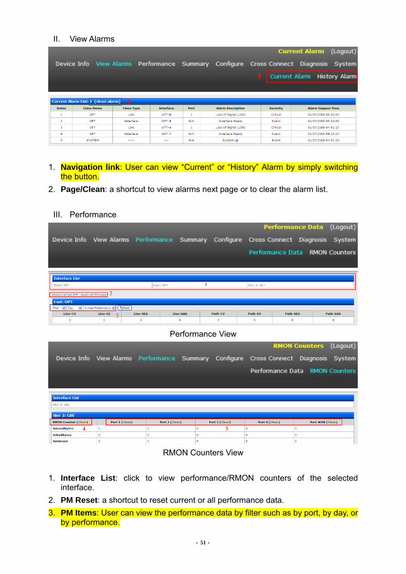
II. View Alarms
1. Navigation link: User can view “Current” or “History” Alarm by simply switching
the button. 2. Page/Clean: a shortcut to view alarms next page or to clear the alarm list.
III. Performance
Performance View
RMON Counters View
1. Interface List: click to view performance/RMON counters of the selected
interface. 2. PM Reset: a shortcut to reset current or all performance data. 3. PM Items: User can view the performance data by filter such as by port, by day, or
by performance.

- 52 -
4. RMON Reset: a shortcut to reset RMON counters of all ports. 5. RMON Reset: a shortcut to reset RMON counters of the selected port.
- 53 -
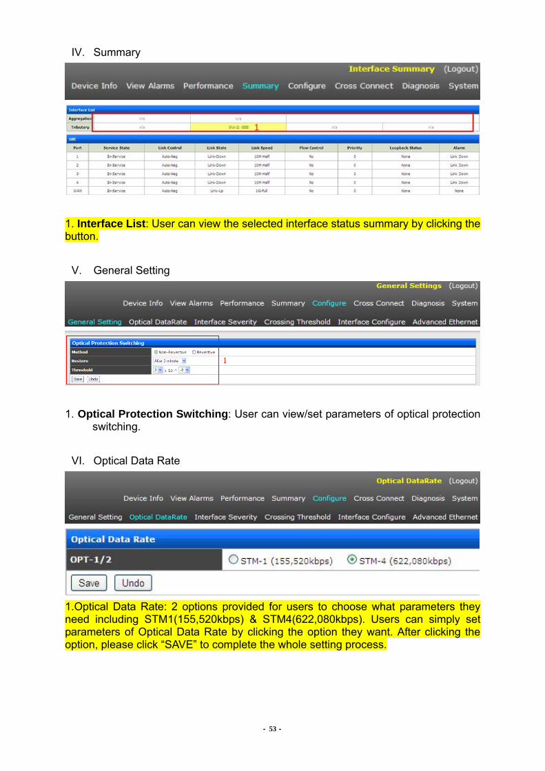
IV. Summary
1. Interface List: User can view the selected interface status summary by clicking the button.
V. General Setting
1. Optical Protection Switching: User can view/set parameters of optical protection
switching.
VI. Optical Data Rate
1.Optical Data Rate: 2 options provided for users to choose what parameters they need including STM1(155,520kbps) & STM4(622,080kbps). Users can simply set parameters of Optical Data Rate by clicking the option they want. After clicking the option, please click “SAVE” to complete the whole setting process.
- 54 -
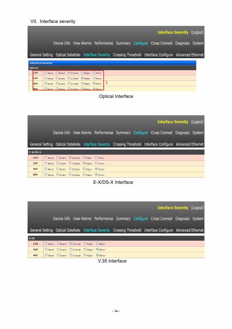
VII. Interface severity
Optical Interface
E-X/DS-X Interface
V.35 Interface
SDH04A User Manual
- 55 -
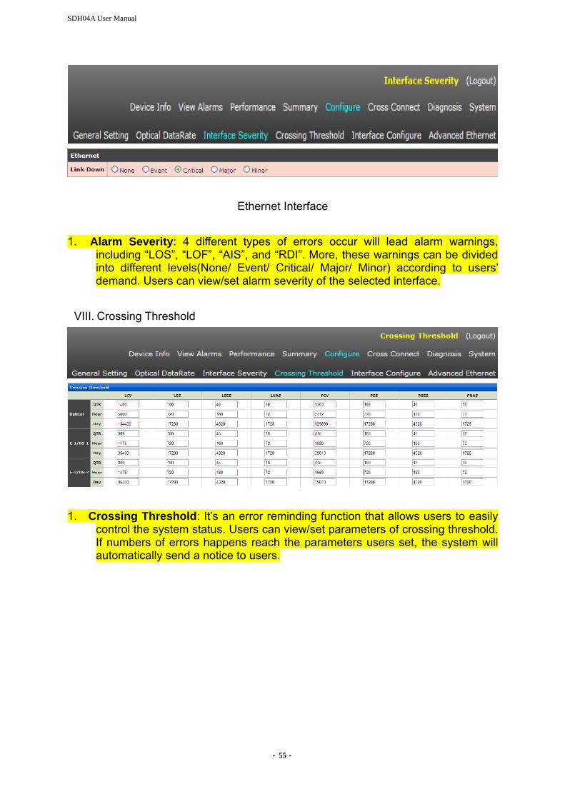
Ethernet Interface 1. Alarm Severity: 4 different types of errors occur will lead alarm warnings,
including “LOS”, “LOF”, “AIS”, and “RDI”. More, these warnings can be divided into different levels(None/ Event/ Critical/ Major/ Minor) according to users’ demand. Users can view/set alarm severity of the selected interface.
VIII. Crossing Threshold
1. Crossing Threshold: It’s an error reminding function that allows users to easily
control the system status. Users can view/set parameters of crossing threshold. If numbers of errors happens reach the parameters users set, the system will automatically send a notice to users.

- 56 -
IX. Interface configure
Optical Interface
E-X/DS-X Interface
V.35 Interface
Ethernet Interface
ET3 Interface
1. Interface List: click to view the configuration of the selected interface. 2. Reload, Default: A shortcut to reload & to reset to default settings.

- 57 -
A. Reload: Once clicking “Reload”, all the parameters setting will be reset and restore to the previous setting.
B. Default: Once clicking “Default”, all the parameters setting will be reset and restore to the default setting.
3. Parameters: the configuration parameters of the interface. 4. Port List: view the configuration data by port filter.
- 58 -
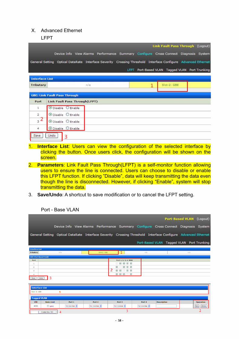
X. Advanced Ethernet
LFPT
1. Interface List: Users can view the configuration of the selected interface by
clicking the button. Once users click, the configuration will be shown on the screen.
2. Parameters: Link Fault Pass Through(LFPT) is a self-monitor function allowing users to ensure the line is connected. Users can choose to disable or enable this LFPT function. If clicking ”Disable”, data will keep transmitting the data even though the line is disconnected. However, if clicking “Enable”, system will stop transmitting the data.
3. Save/Undo: A shortcut to save modification or to cancel the LFPT setting.
Port - Base VLAN
- 59 -
1. Interface List: Users can view the configuration of the selected interface by clicking the button. Once users click, the configuration will be shown on the screen.
2. Parameters: Users can set the port based group parameters by their demand, meaning that users can decide which port can be connected to.
3. Save/Undo: A shortcut to save modification or cancel the port based VLAN setting.
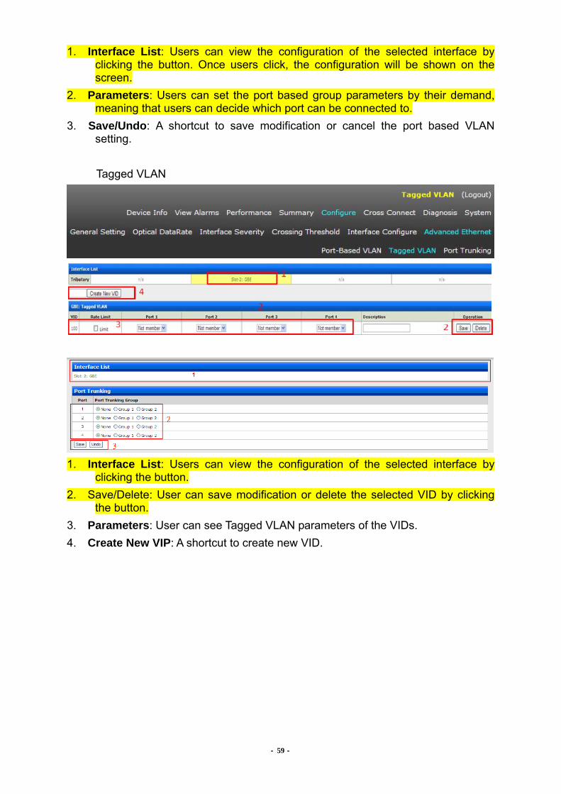
Tagged VLAN
1. Interface List: Users can view the configuration of the selected interface by
clicking the button. 2. Save/Delete: User can save modification or delete the selected VID by clicking
the button. 3. Parameters: User can see Tagged VLAN parameters of the VIDs. 4. Create New VIP: A shortcut to create new VID.
- 60 -
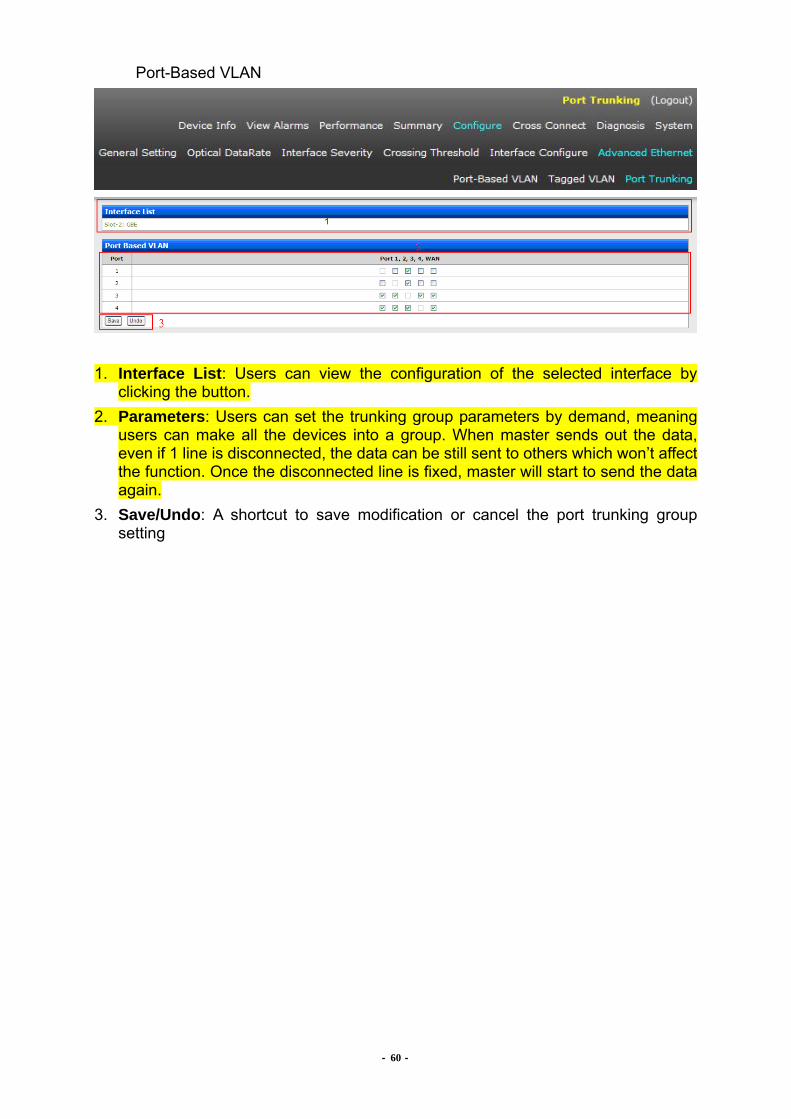
Port-Based VLAN
1. Interface List: Users can view the configuration of the selected interface by
clicking the button. 2. Parameters: Users can set the trunking group parameters by demand, meaning
users can make all the devices into a group. When master sends out the data, even if 1 line is disconnected, the data can be still sent to others which won’t affect the function. Once the disconnected line is fixed, master will start to send the data again.
3. Save/Undo: A shortcut to save modification or cancel the port trunking group setting
SDH04A User Manual
- 61 -
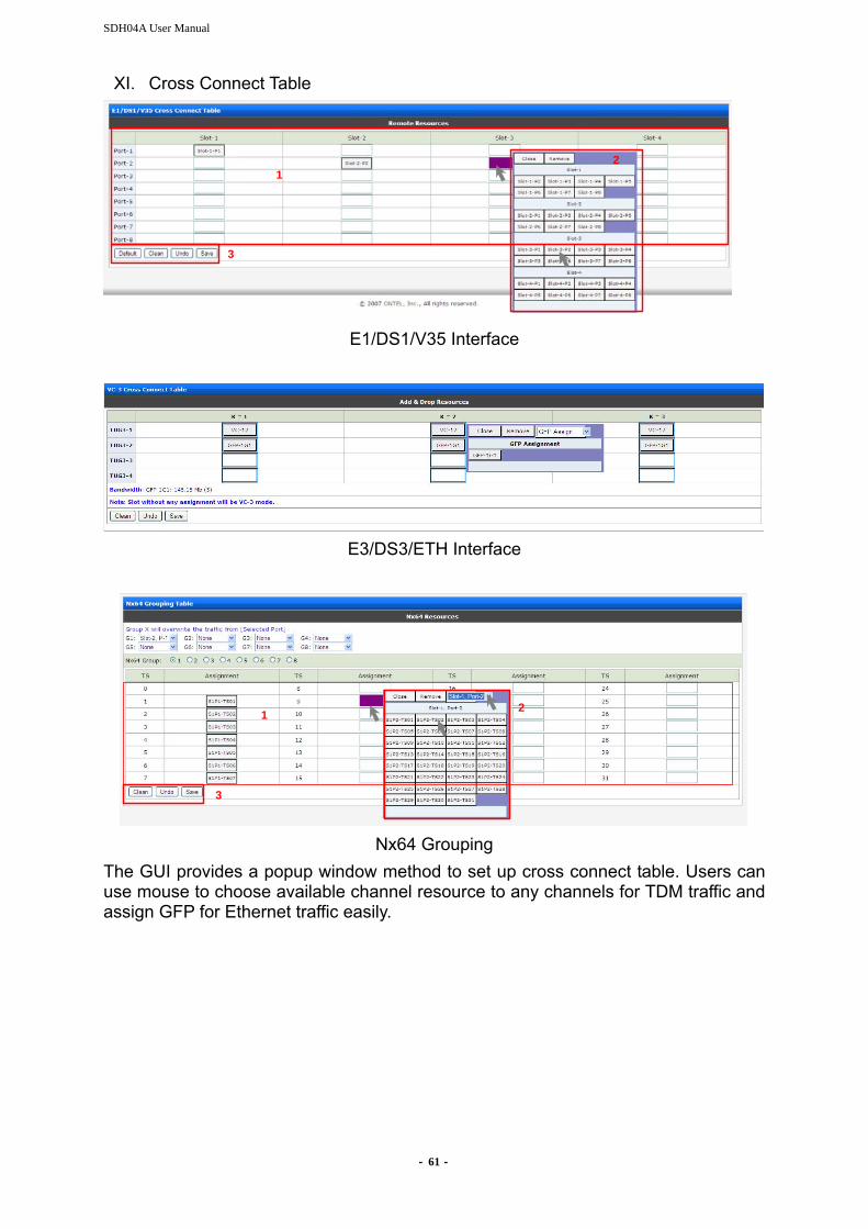
XI. Cross Connect Table
12
3
12
3
E1/DS1/V35 Interface
E3/DS3/ETH Interface
1 2
3
1 2
3
Nx64 Grouping
The GUI provides a popup window method to set up cross connect table. Users can use mouse to choose available channel resource to any channels for TDM traffic and assign GFP for Ethernet traffic easily.

- 62 -
1. Cross Connect Table: the mapping table of tributary interfaces. (Use “drag &
drop” function to establish cross connect table. 2. Available Channel Resource Picker: This is a pop-up window for available
channel resource pick. Click on a available resource to create the mapping. 3. Default/Clean/Undo/Save: A shortcut to load default setting/clean cross connect
table/save & Undo modification. 4. Ethernet Bandwidth: Users can see the list of slot-1/slot-2/slot-3/slot-4 available
Ethernet bandwidth.
XII. Optical Interface Diagnosis
1. Protection Switch: Users can manually switch to OPT-1 or OPT-2 if any of them
is disconnected as a protection. Users can simply click to execute the manual protection switching.
2. Laser Restart: In order to check if the laser is connected, users can restart sending the layer for 2 sec or 90 sec depending on users’ demand. Users can simple click to execute the manual Laser Restart.
- 63 -
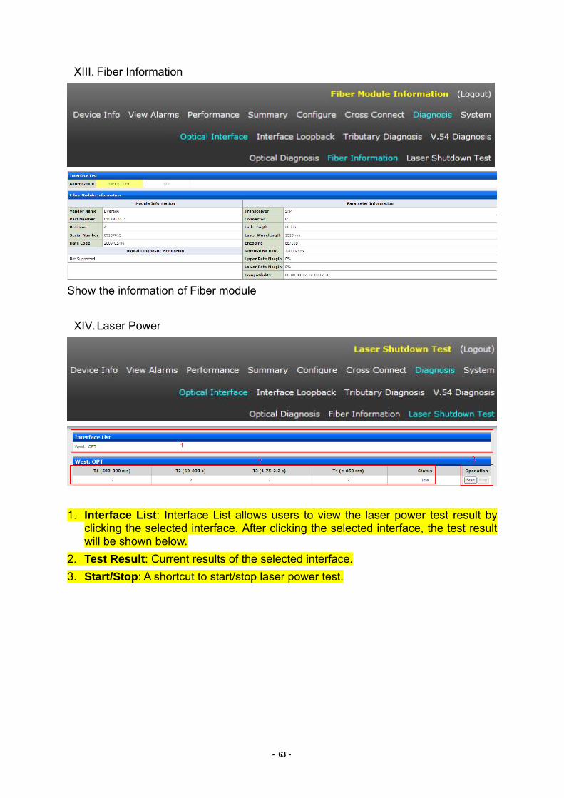
XIII. Fiber Information
Show the information of Fiber module
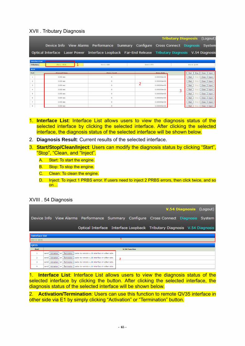
XIV. Laser Power
1. Interface List: Interface List allows users to view the laser power test result by
clicking the selected interface. After clicking the selected interface, the test result will be shown below.
2. Test Result: Current results of the selected interface. 3. Start/Stop: A shortcut to start/stop laser power test.

- 64 -
XV. Interface Loopback
1. Interface List: Interface List allows users to view the loopback status of the
selected interface by clicking the selected interface. After clicking the selected interface, the Loopback Status of the selected interface will be shown below.
2. Loopback: The current loopback settings of the selected interface. 3. Clear/Save: A shortcut to release all loopbacks or to save the modification.
XVI. Far-End Release
Release the remote node OPT loopback status
- 65 -
XVII . Tributary Diagnosis
1. Interface List: Interface List allows users to view the diagnosis status of the
selected interface by clicking the selected interface. After clicking the selected interface, the diagnosis status of the selected interface will be shown below.
2. Diagnosis Result: Current results of the selected interface. 3. Start/Stop/Clean/Inject: Users can modify the diagnosis status by clicking “Start”,
“Stop”, “Clean, and “Inject”. A. Start: To start the engine. B. Stop: To stop the engine. C. Clean: To clean the engine. D. Inject: To inject 1 PRBS error. If users need to inject 2 PRBS errors, then click twice, and so
on…
XVIII . 54 Diagnosis
1. Interface List: Interface List allows users to view the diagnosis status of the selected interface by clicking the button. After clicking the selected interface, the diagnosis status of the selected interface will be shown below. 2. Activation/Termination: Users can use this function to remote QV35 interface in other side via E1 by simply clicking “Activation” or “Termination” button.

- 66 -
XIX. Network Setting
1. DHCP Client: User can decide whether to let client obtain IP address from DHCP
server by clicking Enable button. 2. Network Setting: If the DHCP is disable, users can also manually set the parameters including “Host IP”, “Netmask”, “Gateway”. XX. System Clock
1. Pick a Date: Users can modify the date by clicking the calendar
Once clicking , the calendar picker will pop-up. 2. Date Picker: This is a popup window for date pick. User can click on the date that
wishes system to update automatically. XXI. Audible

- 67 -
1. Alarm Cut Off: a shortcut to execute alarm cut off. XXII. Synchronous
Timing Source: select the Free-run or Recovery mode XXIII . Node Nickname
Description: Users can give node a nickname by demands. After typing the nickname users, users have to click “Save” to complete the setting process. On the other hand, clicking “Undo” will reset the nickname. XXIV . Node ID
Select ID Number: User can set the node ID number by clicking the button. Maximize is 15 ID numbers. Click “Save” to complete the setting process, while click “Undo” to reset the setting.

- 68 -
XXV . Upgrade
Upgrade Status
TFTP parameters
1. Status: Users can view the current status of upgrade process. 2. TFTP Parameters: This window shows the parameters of TFTP system upgrade. 3. TFTP Upgrade: User can click “save”, “Undo”, or “Upgrade Device” to execute
TFTP upgrade. A. Save: To save the setting. B. Undo: To undo the setting. C. Upgrade Device: To execute TFTP upgrade.

- 69 -
XXVI . Backup/Restore
1. Parameters: User can Backup/ Restore TFTP configuration just by simply keying
in the TFTP server IP address, and the filename. System will do Back/Restore afterwards.
2. Backup/Restore/Factory: Users can click “Backup”, “Restore”, or “Factory” according to users’ demand.
A. Backup: To execute backup function. B. Restore: To restore the configuration files by TFTP. C. Factory: To load to factory default.
XXVII . Reboot
1. Boot Type: 3 types of boots allows users to choose. Users can click on anyone to
reboot. After choosing, users have to click “Reboot” button to restart system. XXVIII . Admin
Here user can change the password for accessing web server.
- 70 -
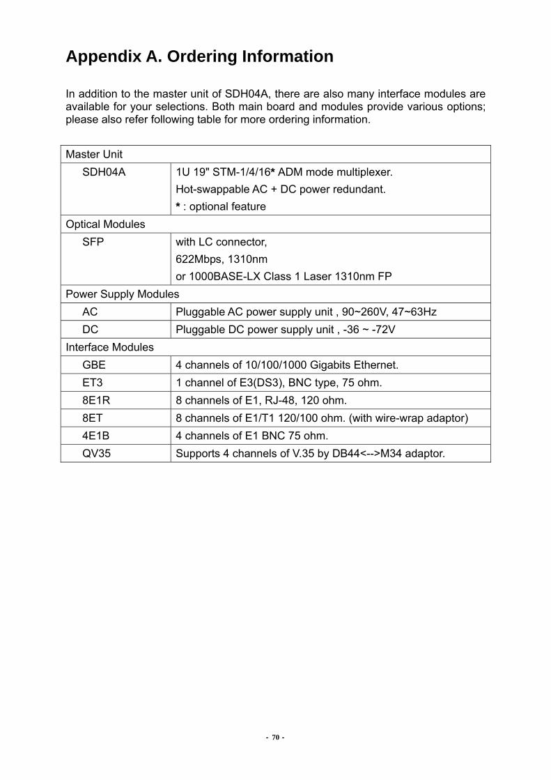
Appendix A. Ordering Information In addition to the master unit of SDH04A, there are also many interface modules are available for your selections. Both main board and modules provide various options; please also refer following table for more ordering information. Master Unit SDH04A 1U 19" STM-1/4/16* ADM mode multiplexer.
Hot-swappable AC + DC power redundant. * : optional feature
Optical Modules SFP with LC connector,
622Mbps, 1310nm or 1000BASE-LX Class 1 Laser 1310nm FP
Power Supply Modules AC Pluggable AC power supply unit , 90~260V, 47~63Hz DC Pluggable DC power supply unit , -36 ~ -72V
Interface Modules GBE 4 channels of 10/100/1000 Gigabits Ethernet. ET3 1 channel of E3(DS3), BNC type, 75 ohm. 8E1R 8 channels of E1, RJ-48, 120 ohm.
8ET 8 channels of E1/T1 120/100 ohm. (with wire-wrap adaptor) 4E1B 4 channels of E1 BNC 75 ohm. QV35 Supports 4 channels of V.35 by DB44<-->M34 adaptor.
SDH04A User Manual
- 71 -
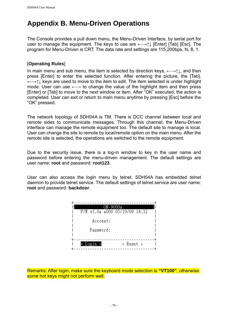
Appendix B. Menu-Driven Operations The Console provides a pull down menu, the Menu-Driven Interface, by serial port for user to manage the equipment. The keys to use are ←→↑↓ [Enter] [Tab] [Esc]. The program for Menu-Driven is CRT. The data rate and settings are 115,200bps, N, 8, 1. [Operating Rules] In main menu and sub menu, the item is selected by direction keys, ←→↑↓, and then press [Enter] to enter the selected function. After entering the picture, the [Tab], ←→↑↓ keys are used to move to the item to edit. The item selected is under highlight mode. User can use ←→ to change the value of the highlight item and then press [Enter] or [Tab] to move to the next window or item. After “OK” executed, the action is completed. User can exit or return to main menu anytime by pressing [Esc] before the “OK” pressed. The network topology of SDH04A is TM. There is DCC channel between local and remote sides to communicate messages. Through this channel, the Menu-Driven interface can manage the remote equipment too. The default site to manage is local. User can change the site to remote by local/remote option on the main menu. After the remote site is selected, the operations are switched to the remote equipment. Due to the security issue, there is a log-in window to key in the user name and password before entering the menu-driven management. The default settings are user name: root and password: root123. User can also access the login menu by telnet. SDH04A has embedded telnet daemon to provide telnet service. The default settings of telnet service are user name: root and password: backdoor.
Remarks: After login, make sure the keyboard mode selection is “VT100”, otherwise some hot keys might not perform well.
- 72 -
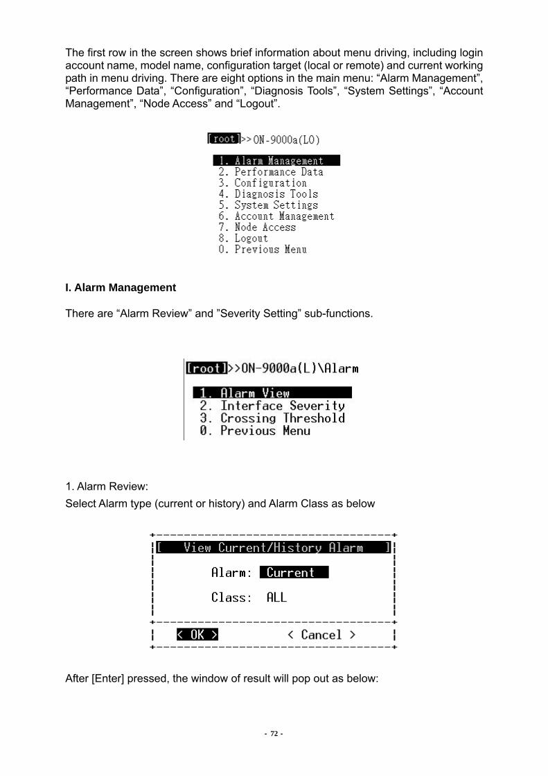
The first row in the screen shows brief information about menu driving, including login account name, model name, configuration target (local or remote) and current working path in menu driving. There are eight options in the main menu: “Alarm Management”, “Performance Data”, “Configuration”, “Diagnosis Tools”, “System Settings”, “Account Management”, “Node Access” and “Logout”.
I. Alarm Management
There are “Alarm Review” and ”Severity Setting” sub-functions.
1. Alarm Review: Select Alarm type (current or history) and Alarm Class as below
After [Enter] pressed, the window of result will pop out as below:
- 73 -
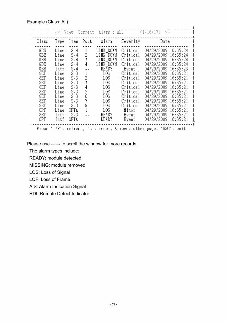
Example (Class: All)
Please use ←→ to scroll the window for more records. The alarm types include: READY: module detected MISSING: module removed LOS: Loss of Signal LOF: Loss of Frame AIS: Alarm Indication Signal RDI: Remote Defect Indicator

SDH04A User Manual
- 74 -
2. Alarm Reset: To reset the current or history alarms. Once “c” is pressed, the current or history log of alarms will be deleted.
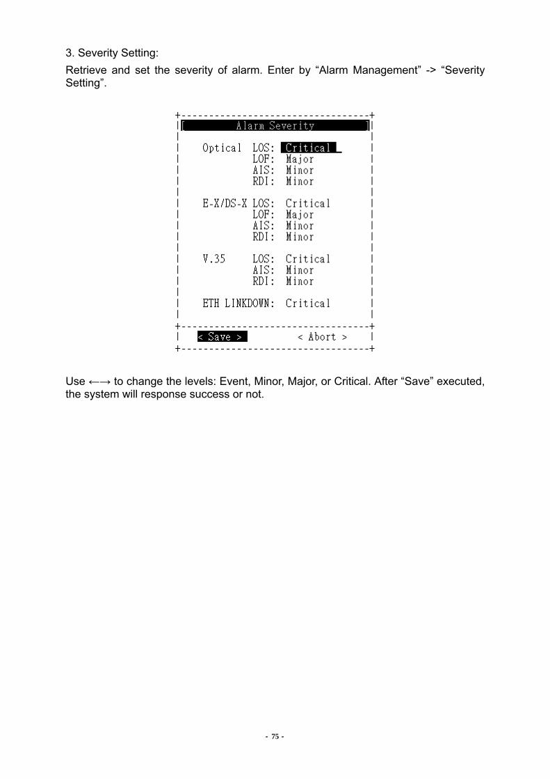
- 75 -
3. Severity Setting: Retrieve and set the severity of alarm. Enter by “Alarm Management” -> “Severity Setting”.
Use ←→ to change the levels: Event, Minor, Major, or Critical. After “Save” executed, the system will response success or not.

- 76 -
4. Crossing Threshold: Retrieve and set the severity of Threshold by entering “Alarm Management” -> “Crossing Threshold”.
Use ←→ to change the parameter. After “Save” executed, the system will response success or not.

- 77 -
II. Performance Data There are “PM Retrieve” and “RMON Counters” sub functions. 1. PM Retrieve:
In this window user can select Item, Port, Type of PM and the Item of PM. The Type could be: “Day”, “Hour” and “Quarter”. The Item could be: “Line-CV”, “Line-ES”, “Line-SES”, “Line-UAS”, “Path-CV”, “Path -ES”, “Path -SES” or “Path -UAS”:

- 78 -
2. PM Reset: To reset the PM values. Once “c” is pressed, the PM values will be reset to 0.
The options are: “c”: Reset the PM of current interval of Quarter and Day. “C”: Reset all PM, including all intervals of the Quarter and Day. 3. RMON Counters:
Statistic counters could be used to performance monitoring or to check problems in the network.
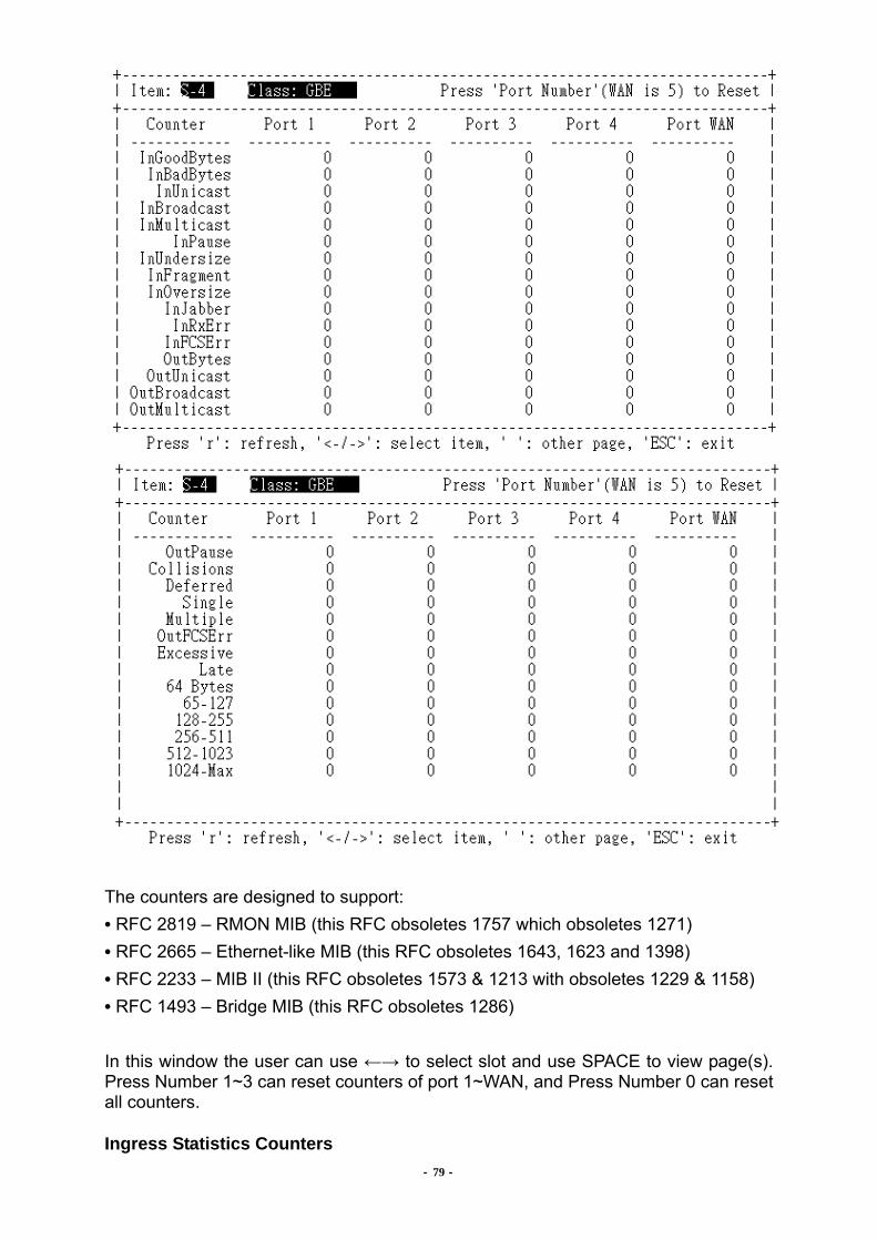
- 79 -
The counters are designed to support: • RFC 2819 – RMON MIB (this RFC obsoletes 1757 which obsoletes 1271) • RFC 2665 – Ethernet-like MIB (this RFC obsoletes 1643, 1623 and 1398) • RFC 2233 – MIB II (this RFC obsoletes 1573 & 1213 with obsoletes 1229 & 1158) • RFC 1493 – Bridge MIB (this RFC obsoletes 1286) In this window the user can use ←→ to select slot and use SPACE to view page(s). Press Number 1~3 can reset counters of port 1~WAN, and Press Number 0 can reset all counters.
Ingress Statistics Counters

- 80 -
InGoodByte: The sum of lengths of all good Ethernet frames received, that is frames those are not bad frames. InBadBytes: The sum of lengths of all bad Ethernet frames received not counting Preamble. InUnicast: The number of good frames received that have a Unicast destination MAC address. InBroadcast: The number of good frames received that have a Broadcast destination MAC address. InMulticasts: The number of good frames received that have a Multicast destination MAC address. InPause: The number of good Flow Control frames received. InUndersize: Total frames received with a length of less than 64 octets but with a valid FCS. InFragment: Total frames received with a length of less than 64 octets and an invalid FCS. InOversize: Total frames received with a length of more than MaxSize octets but with a valid FCS. InJabber: Total frames received with a length of more than MaxSize octets but with an invalid FCS. InRxErr: Total frames received with an Rx_Error event seen by the receive side of the MAC. InFCSErr: Total frames received with a CRC error not counted in InFragments, InJabber. Egress Statistics Counters OutBytes: The sum of lengths of all Ethernet frames sent from this MAC. This includes Flow Control frames and partial frames transmitted due to collisions. OutUnicast: The number of frames sent that have a Unicast destination MAC address. This does not include frames dropped due to excessive collisions nor frames counted in OutFCSErr. OutBroadcast: The number of good frames sent that have a Broadcast destination MAC address. This does not include 802.3 Flow Control frames, nor frames dropped due to excessive collisions nor frames counted in OutFCSErr. OutMulticast: The number of good frames sent that had a Multicast destination MAC address. This does not include 802.3 Flow Control messages, nor frames counted in OutPause nor does it include Broadcast frames counted in OutBroadcasts. OutPause: The number of Flow Control frames sent. Collisions: The number of collision events seen by the MAC not including those counted in Late or Excessive. Deferred: The total number of successfully transmitted frames that were delayed because the medium was busy during the first attempt and then the frame was transmitted without any collisions (this counter is valid in half-duplex mode only.) Single: The total number of successfully transmitted frames that experienced exactly one collision. This counter is applicable in half-duplex only. Multiple: The total number of successfully transmitted frames that experienced more than one collision. This counter is applicable in half-duplex only. OutFCSErr: The number of frames transmitted incorrectly due to an internal MAC transmits error, for example, bad CRC detected when the frame was read from memory. Excessive: The number frames dropped in the transmit MAC due to excessive collision condition. This counter is applicable in half-duplex only.

- 81 -
Late: The number of late collision events seen by the MAC. Histogram Counters 64Bytes: Total frames received and transmitted with a length of exactly 64 octets, including those with errors. 64-127: Total frames received and transmitted with a length of between 65 and 127 octets inclusive, including those with errors. 128-255: Total frames received and transmitted with a length of between 128 and 255 octets inclusive, including those with errors. 256-511: Total frames received and transmitted with a length of between 256 and 511 octets inclusive, including those with errors. 512-1023: Total frames received and transmitted with a length of between 512 and 1023 octets inclusive, including those with errors. 1024-Max:Total frames received and transmitted with a length of between 1024 and MaxSize octets inclusive, including those with errors. III. Configuration: There are “Interface Summary”, “General Settings”, “Optical Date Rate” “Optical Interface”, “E-X/DS-X Interface”, “V.35 Interface”, “Ethernet Interface”, “Advanced ETH Setup”, “Cross Connect Tab” and “Reset Interface”.
1. Interface Summary: Retrieve the summary report. Use ←→ to select the Item. For optical interface, user can get:
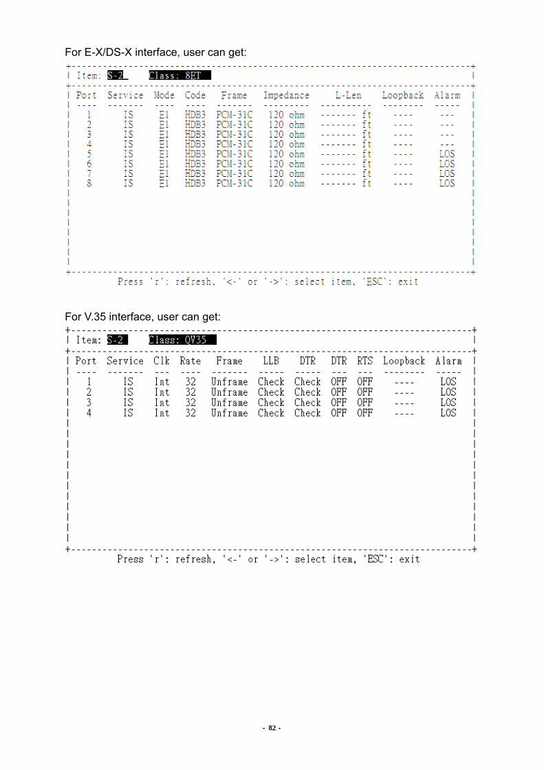
- 82 -
For E-X/DS-X interface, user can get:
For V.35 interface, user can get:

- 83 -
For Ethernet interface, user can get:
2. General Settings: Here user can set optical protection switch to “Non-Revertive” or “Revertive” and WTR Delay time based on fiber signal fail (LOS , LOF) and even set up the BER threshold to do APS switch. All of this optical line protection is followed by ITU Rec. G.783.

- 84 -
3. Optical Interface:
Here user can set optical Date Rate in OPT 1/2 as below: STM-1 TM STM-4 TM STM-16 TM STM-1 ADM STM-4 ADM Remarks 1. After setting, users need to re-set power to ensure the latest setting.
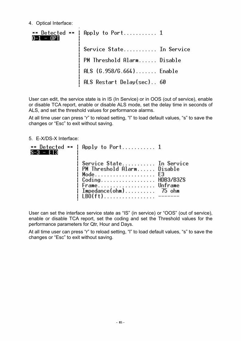
- 85 -
4. Optical Interface:
User can edit, the service state is in IS (In Service) or in OOS (out of service), enable or disable TCA report, enable or disable ALS mode, set the delay time in seconds of ALS, and set the threshold values for performance alarms. At all time user can press “r” to reload setting, “l” to load default values, “s” to save the changes or “Esc” to exit without saving. 5. E-X/DS-X Interface:
User can set the interface service state as “IS” (in service) or “OOS” (out of service), enable or disable TCA report, set the coding and set the Threshold values for the performance parameters for Qtr, Hour and Days. At all time user can press “r” to reload setting, “l” to load default values, “s” to save the changes or “Esc” to exit without saving.

- 86 -
6. V.35 Interface:
Here user can set the service state as “IS” or “OOS”, set the clock mode, set the Data rate, set framing mode, enable V.54 detection, set to ignore DTR or LLB signals, set Interface Mode. DTR and LLB signals are from V.35 DTE, but some DTE do not provide them. User can set “Ignore” to ignore V.35 alarms caused by DTR and LLB signals. In Interface Mode setting, user can set “DCE to DTE” or “DCE to DCE”. In normal application, SDH04A is a DCE equipment and connects to DTE equipment of end customer. Sometimes for other application, users want to connect SDH04A to another DCE equipment. The unit provides flexibility for switching “DCE-DTE” and “DCE-DCE” mode. In “DCE-DCE” mode, user must use crossover cable to link two DCE equipments. At all time user can press “r” to reload setting, “l” to load default values, “s” to save the changes or “Esc” to exit without saving.

SDH04A User Manual
- 87 -
6. Ethernet Interface:
Here user can set the service state, speed rate, set flow control, Default Priority, Double VLAN tag, Default VLAN ID, Egress Rate and Ingress Rate Settings. The user can set more advanced functions like enabling flow control or limiting the traffic according the traffic-type like broadcast frames or ARP. Also user can set other parameters like Committed Burst size (CBS) and/or Excess Burst size (EBS). Note: Only change the default values if you are sure of the values to configure. A wrong configuration will leave to unpredictable results. When enabling Flow control, there is flow control at the ingress rate configured and not package lost is going to happen. Usually this option should be disabled. If flow control in Ingress rate is enabled, be sure to set flow control for this port in the second option for the global GBE menu. If this is not the case, ingress rate won’t work. The scheme for implementing ingress rate limiting is a leaky bucket. Imagine a bucket that drains tokens constantly at a rated called Committed Information Rate (CIR) (Rate option in the menu) and the bucket gets replenished with tokens whenever a frames is allowed to go through the bucket. All calculations for this bucket are carried out in tokens.
Bucket Increment (Hex) controls how many tokens need to get added after accepting each frame. It is recommended that this value is 0xAE. EBS_limit is directly proportional to the amount of bytes that can be accommodated as part of the frame burst. Recommended value = 0xFFFFF0. CBS_limit signifies the minimum token depth necessary to allow frames go through. Recommended value = 0x060000. Next figure explains better the concept of a leaky bucket:
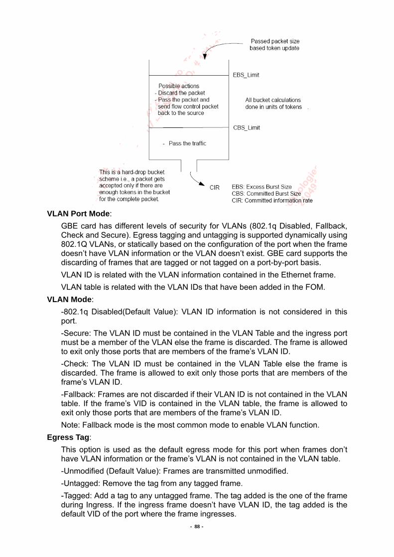
- 88 -
VLAN Port Mode:
GBE card has different levels of security for VLANs (802.1q Disabled, Fallback, Check and Secure). Egress tagging and untagging is supported dynamically using 802.1Q VLANs, or statically based on the configuration of the port when the frame doesn’t have VLAN information or the VLAN doesn’t exist. GBE card supports the discarding of frames that are tagged or not tagged on a port-by-port basis. VLAN ID is related with the VLAN information contained in the Ethernet frame. VLAN table is related with the VLAN IDs that have been added in the FOM.
VLAN Mode: -802.1q Disabled(Default Value): VLAN ID information is not considered in this port. -Secure: The VLAN ID must be contained in the VLAN Table and the ingress port must be a member of the VLAN else the frame is discarded. The frame is allowed to exit only those ports that are members of the frame’s VLAN ID. -Check: The VLAN ID must be contained in the VLAN Table else the frame is discarded. The frame is allowed to exit only those ports that are members of the frame’s VLAN ID. -Fallback: Frames are not discarded if their VLAN ID is not contained in the VLAN table. If the frame’s VID is contained in the VLAN table, the frame is allowed to exit only those ports that are members of the frame’s VLAN ID. Note: Fallback mode is the most common mode to enable VLAN function.
Egress Tag: This option is used as the default egress mode for this port when frames don’t have VLAN information or the frame’s VLAN is not contained in the VLAN table. -Unmodified (Default Value): Frames are transmitted unmodified. -Untagged: Remove the tag from any tagged frame. -Tagged: Add a tag to any untagged frame. The tag added is the one of the frame during Ingress. If the ingress frame doesn’t have VLAN ID, the tag added is the default VID of the port where the frame ingresses.

- 89 -
Ingress Tag: GBE supports the discarding of frames that are tagged or not tagged on a port-by-port basis. No discard is the default value.
At all time user can press “r” to reload setting, “l” to load default values, “s” to save the changes or “Esc” to exit without saving.

- 90 -
7. Advanced ETH Setup: There are “Port-Based VLAN”, “Tagged VLAN”, ”Port Trunking”, ”MAC Table list and sub options.
7.1. Port-Based VLAN
User can edit the port-based VLAN setting here by using Arrow keys and SPACE key. At all time user can press “r” to reload setting, “l” to load default values, “s” to save the changes or “Esc” to exit without saving. 7.2. Tagged VLAN:
User can edit the tagged VLAN setting of QSW & GBE. At all time user can press “r” to reload setting, “l” to load default values, “s” to save the changes or “Esc” to exit without saving.
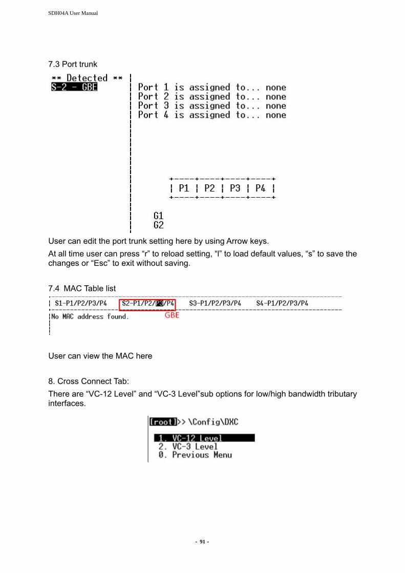
SDH04A User Manual
- 91 -
7.3 Port trunk
User can edit the port trunk setting here by using Arrow keys. At all time user can press “r” to reload setting, “l” to load default values, “s” to save the changes or “Esc” to exit without saving. 7.4 MAC Table list
User can view the MAC here 8. Cross Connect Tab: There are “VC-12 Level” and “VC-3 Level”sub options for low/high bandwidth tributary interfaces.
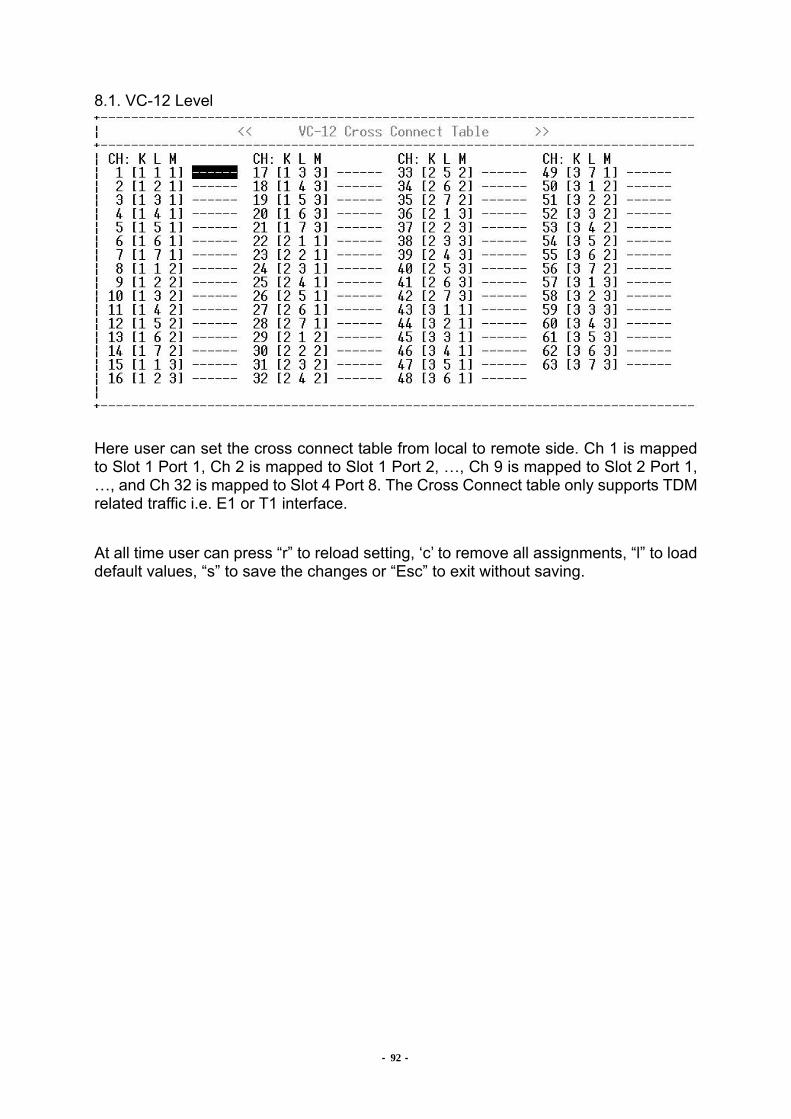
- 92 -
8.1. VC-12 Level
Here user can set the cross connect table from local to remote side. Ch 1 is mapped to Slot 1 Port 1, Ch 2 is mapped to Slot 1 Port 2, …, Ch 9 is mapped to Slot 2 Port 1, …, and Ch 32 is mapped to Slot 4 Port 8. The Cross Connect table only supports TDM related traffic i.e. E1 or T1 interface. At all time user can press “r” to reload setting, ‘c’ to remove all assignments, “l” to load default values, “s” to save the changes or “Esc” to exit without saving.

- 93 -
8.2. VC-3 Level
Here user can set the VC-3 cross connect table for Ethernet interface. “GFP-G1” is the bandwidth for all Slot . At all time user can press “ r ” to reload setting, “c” to remove all assignments, “s” to save the changes or “Esc” to exit without saving. 8.3. Nx64 Grouping
Here user can set “Nx64k Group” in CO side and E1/V.35 “Subgroups” channels in RT side. Please refer to Appendix F. for detail Nx64K description.
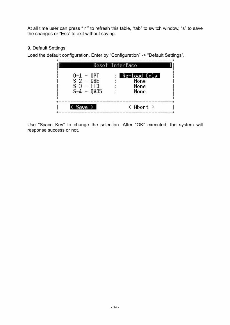
- 94 -
At all time user can press “ r ” to refresh this table, “tab” to switch window, “s” to save the changes or “Esc” to exit without saving. 9. Default Settings: Load the default configuration. Enter by “Configuration” -> “Default Settings”.
Use “Space Key” to change the selection. After “OK” executed, the system will response success or not.
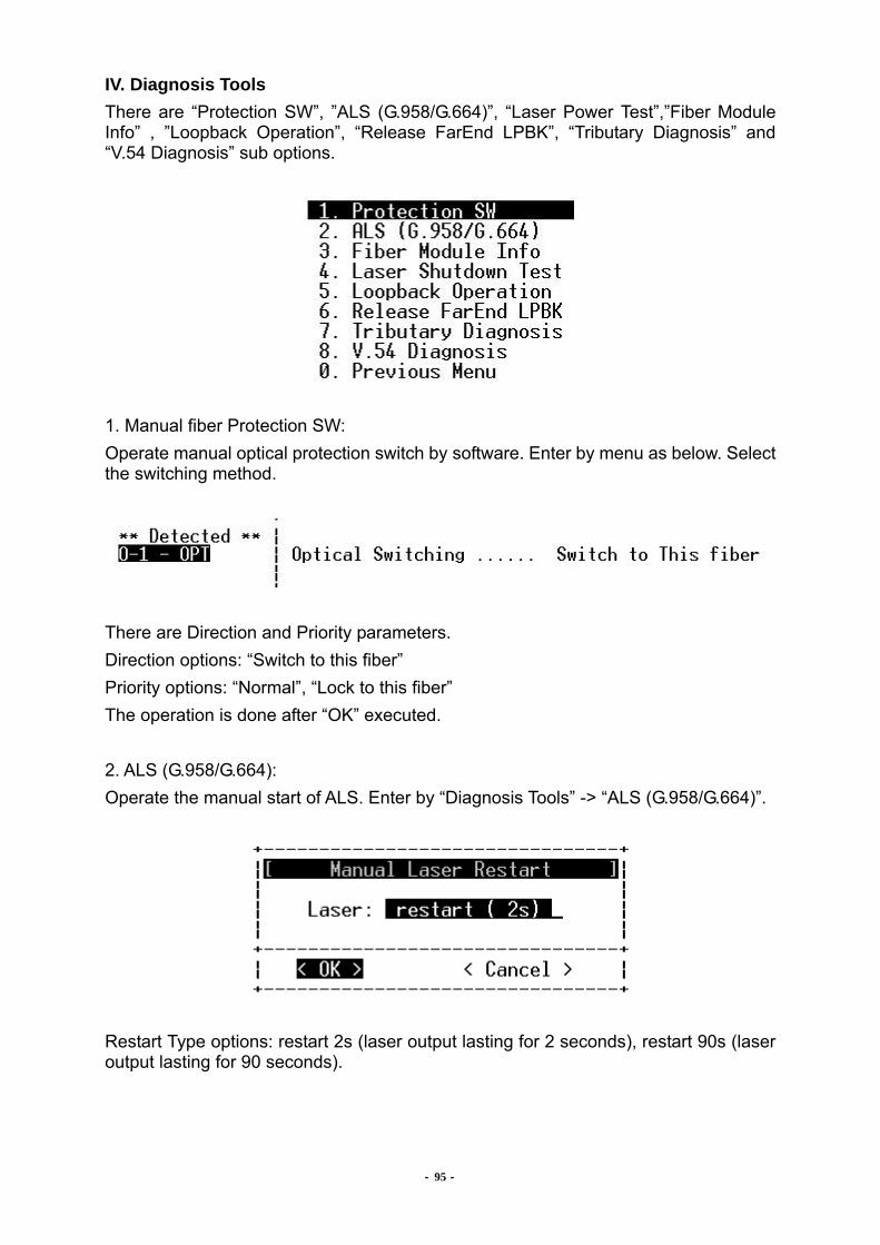
- 95 -
IV. Diagnosis Tools There are “Protection SW”, ”ALS (G.958/G.664)”, “Laser Power Test”,”Fiber Module Info” , ”Loopback Operation”, “Release FarEnd LPBK”, “Tributary Diagnosis” and “V.54 Diagnosis” sub options.
1. Manual fiber Protection SW: Operate manual optical protection switch by software. Enter by menu as below. Select the switching method.
There are Direction and Priority parameters. Direction options: “Switch to this fiber” Priority options: “Normal”, “Lock to this fiber” The operation is done after “OK” executed. 2. ALS (G.958/G.664): Operate the manual start of ALS. Enter by “Diagnosis Tools” -> “ALS (G.958/G.664)”.
Restart Type options: restart 2s (laser output lasting for 2 seconds), restart 90s (laser output lasting for 90 seconds).

- 96 -
3. Fiber Module Info:
User can check the fiber module information on this item
4. Laser Power Test: Operate the test of laser power. Enter by “Diagnosis Tools” -> “Laser Power Test”.
At all time user can press “r” to refresh list, “s” to start the test or “Esc” to exit without saving. This function can let the user test remote FOM ALS function from local FOM CLI. The user can get T1 /T2 /T3 /T4 period to make sure if remote FOM meet ITU G.958 or G.664 spec. from CLI easily.
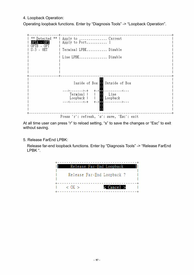
- 97 -
4. Loopback Operation: Operating loopback functions. Enter by “Diagnosis Tools” -> “Loopback Operation”.
At all time user can press “r” to reload setting, “s” to save the changes or “Esc” to exit without saving. 5. Release FarEnd LPBK: Release far-end loopback functions. Enter by “Diagnosis Tools” -> “Release FarEnd
LPBK “.
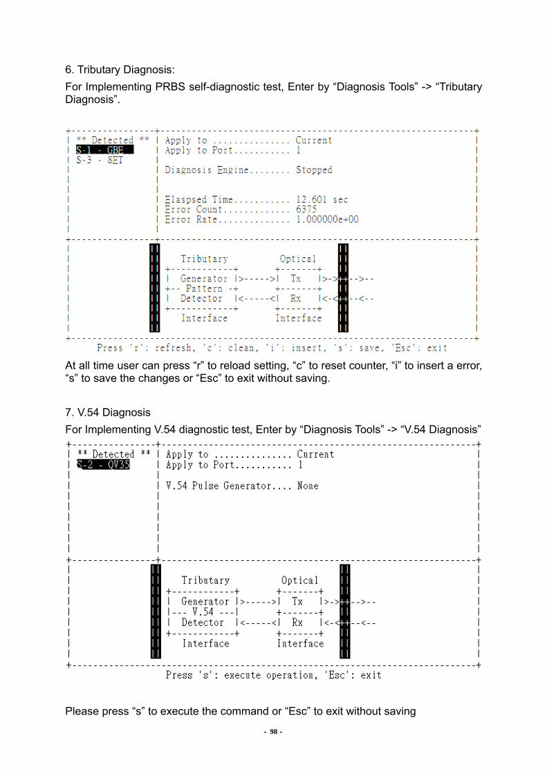
- 98 -
6. Tributary Diagnosis: For Implementing PRBS self-diagnostic test, Enter by “Diagnosis Tools” -> “Tributary Diagnosis”.
At all time user can press “r” to reload setting, “c” to reset counter, “i” to insert a error, “s” to save the changes or “Esc” to exit without saving. 7. V.54 Diagnosis For Implementing V.54 diagnostic test, Enter by “Diagnosis Tools” -> “V.54 Diagnosis”
Please press “s” to execute the command or “Esc” to exit without saving

SDH04A User Manual
- 99 -
VII. System Settings There are “System Version” “Network Configure”, “Date and Time”, “Upgrade System”, “Audible Setting”, “Configure Backup”, “System Reset” and “Manufactory Report” sub options.
1. System Version: Retrieve the version of equipment and it will show the version information.
2. Network Configure: Set the IP address of the equipment. Enter by “System Settings” -> “Network Configure”. The following options are available
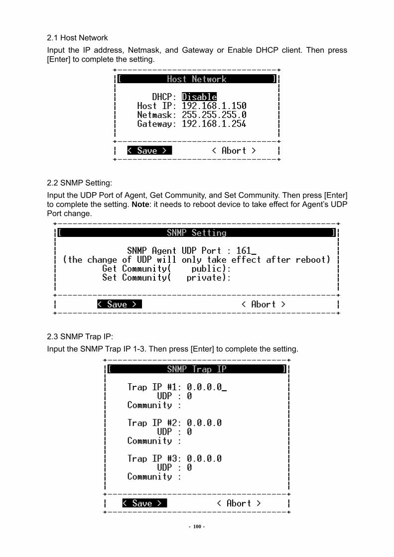
- 100 -
2.1 Host Network Input the IP address, Netmask, and Gateway or Enable DHCP client. Then press [Enter] to complete the setting.
2.2 SNMP Setting: Input the UDP Port of Agent, Get Community, and Set Community. Then press [Enter] to complete the setting. Note: it needs to reboot device to take effect for Agent’s UDP Port change.
2.3 SNMP Trap IP: Input the SNMP Trap IP 1-3. Then press [Enter] to complete the setting.
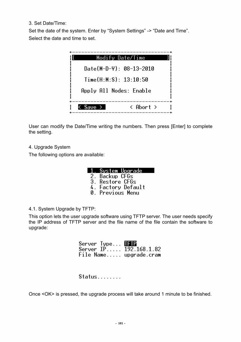
- 101 -
3. Set Date/Time: Set the date of the system. Enter by “System Settings” -> “Date and Time”. Select the date and time to set.
User can modify the Date/Time writing the numbers. Then press [Enter] to complete the setting. 4. Upgrade System The following options are available:
4.1. System Upgrade by TFTP: This option lets the user upgrade software using TFTP server. The user needs specify the IP address of TFTP server and the file name of the file contain the software to upgrade:
Once <OK> is pressed, the upgrade process will take around 1 minute to be finished.
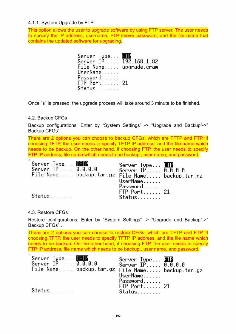
- 102 -
4.1.1. System Upgrade by FTP: This option allows the user to upgrade software by using FTP server. The user needs to specify the IP address, username, FTP server password, and the file name that contains the updated software for upgrading.
Once “s” is pressed, the upgrade process will take around 3 minute to be finished. 4.2. Backup CFGs Backup configurations: Enter by “System Settings” -> “Upgrade and Backup”->” Backup CFGs”. There are 2 options you can choose to backup CFGs, which are TFTP and FTP. If choosing TFTP, the user needs to specify TFTP IP address, and the file name which needs to be backup. On the other hand, if choosing FTP, the user needs to specify FTP IP address, file name which needs to be backup., user name, and password.
4.3. Restore CFGs Restore configurations: Enter by “System Settings” -> “Upgrade and Backup”->” Backup CFGs”.. There are 2 options you can choose to restore CFGs, which are TFTP and FTP. If choosing TFTP, the user needs to specify TFTP IP address, and the file name which needs to be backup. On the other hand, if choosing FTP, the user needs to specify FTP IP address, file name which needs to be backup., user name, and password.
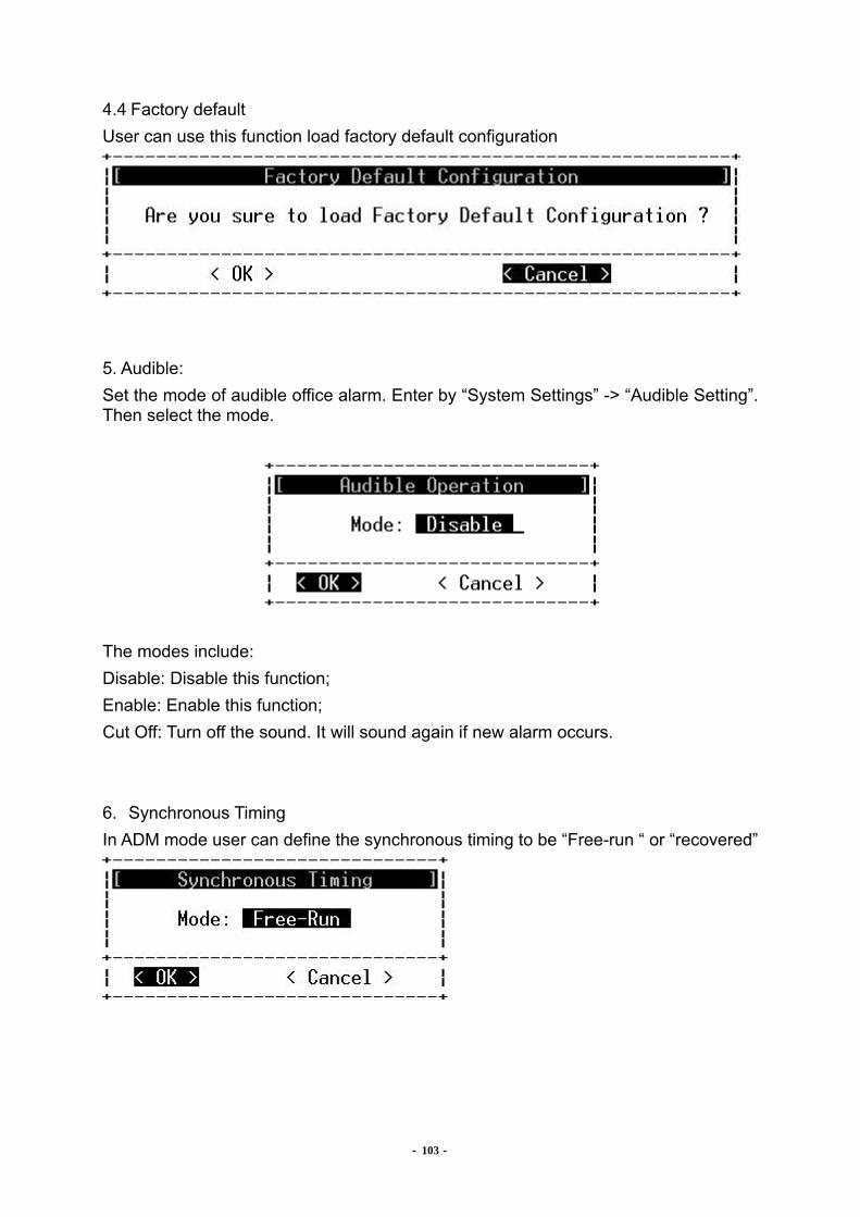
- 103 -
4.4 Factory default User can use this function load factory default configuration
5. Audible: Set the mode of audible office alarm. Enter by “System Settings” -> “Audible Setting”. Then select the mode.
The modes include: Disable: Disable this function; Enable: Enable this function; Cut Off: Turn off the sound. It will sound again if new alarm occurs. 6. Synchronous Timing In ADM mode user can define the synchronous timing to be “Free-run “ or “recovered”
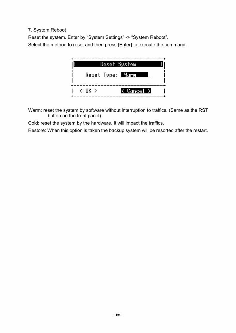
- 104 -
7. System Reboot Reset the system. Enter by “System Settings” -> “System Reboot”. Select the method to reset and then press [Enter] to execute the command.
Warm: reset the system by software without interruption to traffics. (Same as the RST
button on the front panel) Cold: reset the system by the hardware. It will impact the traffics. Restore: When this option is taken the backup system will be resorted after the restart.
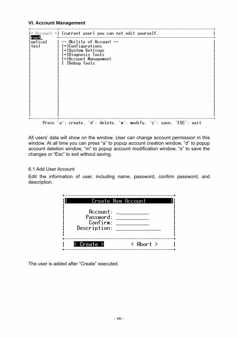
- 105 -
VI. Account Management
All users’ data will show on the window. User can change account permission in this window. At all time you can press “a” to popup account creation window, “d” to popup account deletion window, “m” to popup account modification window, “s” to save the changes or “Esc” to exit without saving. 6.1 Add User Account Edit the information of user, including name, password, confirm password, and description.
The user is added after “Create” executed.
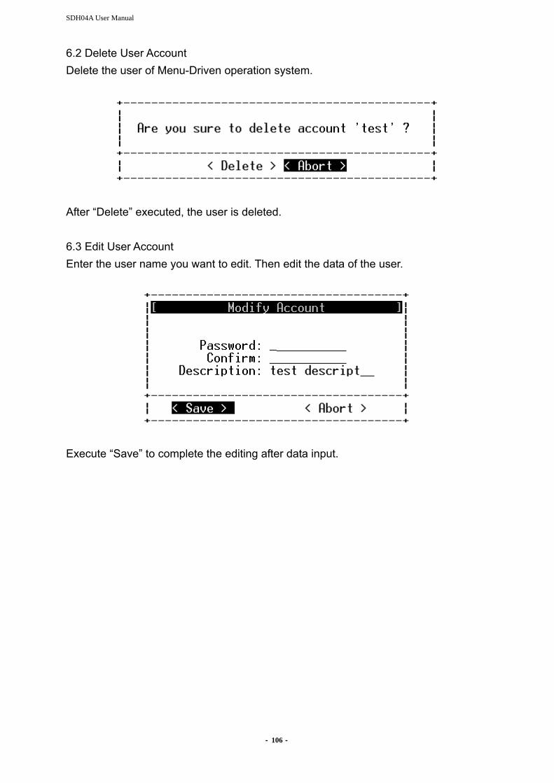
SDH04A User Manual
- 106 -
6.2 Delete User Account Delete the user of Menu-Driven operation system.
After “Delete” executed, the user is deleted. 6.3 Edit User Account Enter the user name you want to edit. Then edit the data of the user.
Execute “Save” to complete the editing after data input.

- 107 -
VII. Node Access The following options are available:
7.1 Node Selection Set the site, local side or remote side, to manage by the Menu-Driven interface. Enter by picture as below.
Press ↑↓ to select Local or Remote site. The name of site is shown on the top of the menu window to indicate the site under manages. All the operations are done to this site after selected. 7.2 Node Description Edit the description of node
Execute “Save” to complete the editing after data input.

- 108 -
7.3 Node ID Number Edit the ID Number of node

SDH04A User Manual
- 109 -
Appendix C. LCD Operations on for SDH04A The operations of LCD interface will be described here. Two rows and 16 characters per row on the panel UR: Upper Row; BR: Bottom Row Four keypads on the right side of LCD panel: [ESC] [<=] [ENT+] [=>] [ESC]: return to the previous view or abandon [<=][=>]: move cursor [ENT+]: select, execute, or change number I. Operation Procedures: UR is the previous hierarchy items of BR. Use [<=] or [=>] to move and [ENT+] to select the item of BR. The item selected will show on UR. The number on the left is the position in the hierarchy. The character on the right of BR reminds you the next keypad to operate. II. Key Lock Protection: LCD is protected by key lock. After booting or there is no key pressed in 10 minutes, LCD will enter key lock mode. Till you input the correct password, LCD will leave key lock mode and enter normal operation mode. The default password is “6666”. You can change the password by pressing [ENT+] and [=>] at the same time in welcome display (LCD shows model name and host IP). [ENT+] and [ESC] at the same time in welcome display can force LCD to enter key lock mode immediately. III. The List of Function Menu:
ALM: (Alarm Management) VIEW
CURR/HIST ALL / SYS / OPT / E-X/DS-X / V35 / ETH
RST CURR/HIST
SEVER OPT
LOS : CRITICAL / MAJOR / MINOR / NONE / EVENT
LOF : CRITICAL / MAJOR / MINOR / NONE / EVENT
AIS : CRITICAL / MAJOR / MINOR / NONE / EVENT
RDI : CRITICAL / MAJOR / MINOR / NONE / EVENT
E-X/DS-X LOS : CRITICAL / MAJOR / MINOR / NONE / EVENT
LOF : CRITICAL / MAJOR / MINOR / NONE / EVENT
AIS : CRITICAL / MAJOR / MINOR / NONE / EVENT

- 110 -
RDI : CRITICAL / MAJOR / MINOR / NONE / EVENT
V.35 LOS : CRITICAL / MAJOR / MINOR / NONE / EVENT
AIS : CRITICAL / MAJOR / MINOR / NONE / EVENT
RDI : CRITICAL / MAJOR / MINOR / NONE / EVENT
ETH LNKDWN: CRITICAL / MAJOR / MINOR / NONE / EVENT
PM: (Performance Data) VIEW
OPT CURR/HIST
QTR/HOUR/DAY LINE
LCV/LES/LSES/LUAS
PATH PCV/PES/PSES/PUAS
E-X/DS-X Port Number CURR/HIST
QTR/HOUR/DAY Line
LCV/LES/LSES/LUAS
Path PCV/PES/PSES/PUAS
RST CURR/ALL
RMON Slot Number
RMON Data
RMONRST Slot Number
ALL/1/2/3/4/WAN
CFG: (Configuration) SMRY
OPT SVC: IS / OOS
ALS: Enable / Disable
DELAY: 60~300 sec
LPBK: None / Line / Term
Prio: Primary/Secondary
STAT: Active/Standby
ALM: NONE/LOS/LOF/AIS/RDI
E-X/DS-X SVC: IS / OOS
MODE: E1/DS1/E3/DS3
CODE: HDB3/B8ZS / AMI / HDB3/B3ZS

- 111 -
FRAME: UNFRAME/FRAME
IMPED: 120-ohm/100-ohm/75-ohm
LBO:------
LPBK: None / Line / Term
ALM: NONE/LOS/AIS/RDI
ETH SVC: IS / OOS
CTRL: AutoNeg/100MF/10MF/100MH/10MH/1GF
LINK: Up / Down
SPEED: 10M / 100M / 1G
DUPLEX: Half / FULL
FLOW: OFF / ON
PRIO: 0~3
ALM: NONE/LinkDown
GNAL PSW: Revert / Non-Revert
WTR: 0~15 Min.
SWTCA: 1~9
SWSCALE: 10-5~10-9
OPT
ALL / 1 SVC: IS / OOS
TCARPT: Enable /Disable
ALS: Enable /Disable
DELAY: 60~300 sec
TCA
E-X/DS-X ALL 1 2 3 4 5 6 7 8
SVC: IS / OOS
TCARPT: Enable /Disable
MODE: E1/DS1/E3/DS3
CODING: HDB3/B8ZS / AMI / HDB3/B3ZS
FRAME: UNFRAME/FRAME
IMPED: 120-ohm/100-ohm/75-ohm
LBO: ------
TCA
V35
ALL 1 2 3 4 SVC: IS / OOS
CLK: Internal / External / Recovery
RATE: 1~32
FRAME: Unframe / PCM-31C / PCM-30C / PCM-31 / PCM-30
LLB: Normal / Ignore
DTR: Normal / Ignore
V54: Disable/Enable
V54T: 0~60

- 112 -
IMODE: DCE-DTE/DCE-DCE
TDEDGE: Rising_Edge/Falling_Edge
ETH ALL 1 2 3 4 WAN
CFG
SVC: IS / OOS
LINK: AutoNeg/100MF/10MF/100MH/10MH/1GF
FLOW: Enable /Disable
PRIO: 0~4
VLAN
DBVLAN: Enable /Disable
PROVIDER: 0000~FFFF
DEF-VID: 0~4095
FORCE-VID: Enable /Disable
VLANPORT: 802.1Q Disable / Fallback / Check / Secure
EG-TAG: Unmodified / Untagged / Tagged
ING-TAG: None / Drop Untagged / Drop Tagged
EGRESS
EgressRate: 64K~1000M
INGRESS
ING-ENA: Enable /Disable
ING-RATE: 64K~1000M
ING-FLOW: Enable /Disable
UNKUNICAST: Unlimit / limit
UNKBCAST: Unlimit / limit
UNKICAST: Unlimit / limit
MULTICAST: Unlimit / limit
BCAST: Unlimit / limit
MGMT: Unlimit / limit
ARP: Unlimit / limit
BUCKET: 00~FF
CBS: 0000~FFFF
EBS: 0000~FFFF
ADVETH
PORTMODE
TRUNK
PBVLAN
TAGVLAN
NEW / DEL / EDIT
DXC E1/DS1/V35
E3/DS3/ETH
DEFAULT
DIAG: (Diagnosis Tools)
APS: OPTB=>OPTA / OPTA=>OPTB

- 113 -
ALS: Restart(2s) / Test(90s)
LASER: (Laser test) OPTA/OPTB
LPBK E-X/DS-X
Term / Line
FAR-END Release
TRIB E-X/DS-X
1 2 3 4 5 6 7 8 RAT/ERR/TIM
View Result/ Run/Stop / Inject Error /Clean Result
V.54 V35
Activation/Termination
SYS: (System Settings) INFO
F/W / H/W / EPLD / FPGA / S/N / MAC / UPTIME NETWORK
DHCP: Disable / Enable IP: (Set IP Address): user keying MASK: (Set IP Mask): user keying GATE: (Set Gateway): user keying
SNMPCFG UDP / SET / GET
SNMPTRAP TRAP1 / TRAP2 / TRAP3
SYSTIME user keying
UPGRADE TFTP
Tftp server IP: xxx.xxx.xxx.xxx user keying Upgrade file: xxxx.tar.gz user keying
MIRROR: L->R / R->L
AUDIBLE: Disable / Enable
CFGBACK BACKUP
Tftp server IP: xxx.xxx.xxx.xxx user keying file: xxxx.tar.gz user keying
RESTORE Tftp server IP: xxx.xxx.xxx.xxx user keying

- 114 -
file: xxxx.tar.gz user keying FACTORY
REBOOT: Warm / Cold / Restore
NODE: (Node Settings)
NICKNAME: user keying

- 115 -
Appendix D. VLAN Function VLAN is a method of creating independent logical network within a physical network. VLAN Tagging is inserting a VLAN ID into a packet header to identify port group. Switch use VLAN ID to determine which port to send packets. SDH04A can transmit and receive the IEEE 802.1Q complied traffic, for the high performance feature, it can support 256 VLAN IDs. Besides, SDH04A can display VLAN table for each individual Ethernet channel. Application Examples: 1. Environment
EVPL is applied to E-Line interconnection of different users (interconnected via VLAN) between two nodes. It is to adopt VLAN technique to ensure isolation between different user ports.
2. Configuration
3. SDH04A Configuration
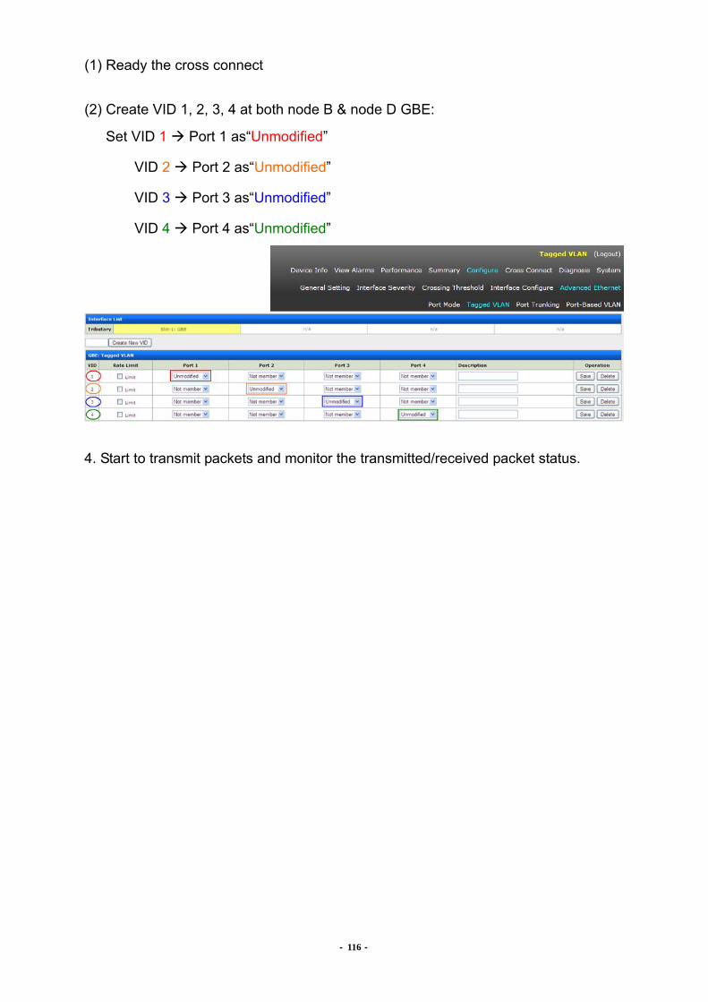
- 116 -
(1) Ready the cross connect (2) Create VID 1, 2, 3, 4 at both node B & node D GBE:
Set VID 1 Port 1 as“Unmodified”
VID 2 Port 2 as“Unmodified”
VID 3 Port 3 as“Unmodified”
VID 4 Port 4 as“Unmodified”
4. Start to transmit packets and monitor the transmitted/received packet status.

- 117 -
Appendix E. Q-in-Q Function Application Examples: 1. Environment
If the same VLAN ID (e.g. VID 5) environment is applied to the E-Line interconnection of different users between two nodes. Customers need to adopt Q-in-Q technique to isolate the traffic between different user ports.

SDH04A User Manual
- 118 -
3. SDH04A Configuration (1) Ready the cross connect (2) Create VID 100, 200, 300, 400 at both node B & node D GBE:
Set VID 100 Port 1 as“Unmodified”
VID 200 Port 2 as“Unmodified”
VID 300 Port 3 as“Unmodified”
VID 400 Port 4 as“Unmodified”
(3) Set node B & node D GBE WAN Port: - Double VLAN: Enable - Provider Tag : 8100
- VLAN mode: Check - Egress Tag: Unmodified
(4) Configure GBE parameters at both node B & node D GBE Port 1: - Force VID: Enable
- Default VID: 100 - VLAN Mode: Fallback - Egress Tag: Tagged
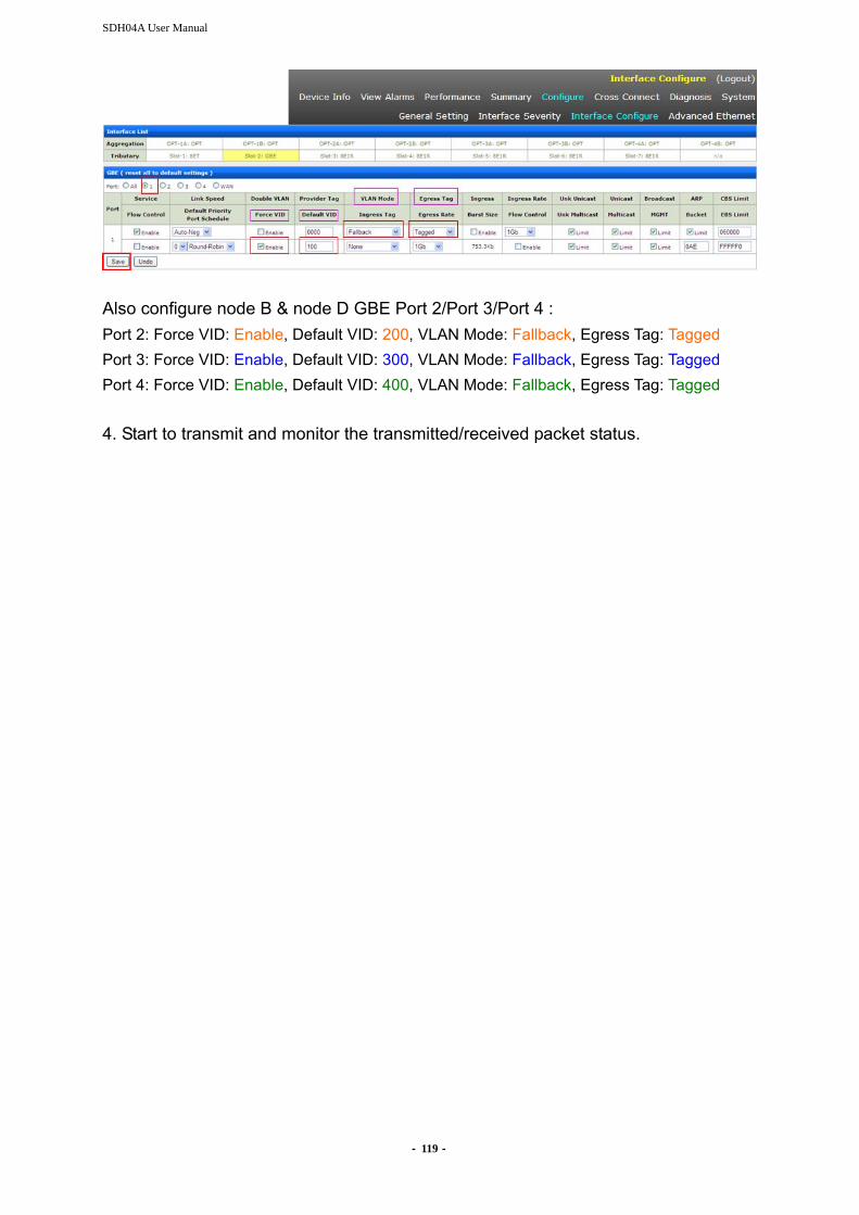
SDH04A User Manual
- 119 -
Also configure node B & node D GBE Port 2/Port 3/Port 4 : Port 2: Force VID: Enable, Default VID: 200, VLAN Mode: Fallback, Egress Tag: Tagged Port 3: Force VID: Enable, Default VID: 300, VLAN Mode: Fallback, Egress Tag: Tagged Port 4: Force VID: Enable, Default VID: 400, VLAN Mode: Fallback, Egress Tag: Tagged 4. Start to transmit and monitor the transmitted/received packet status.
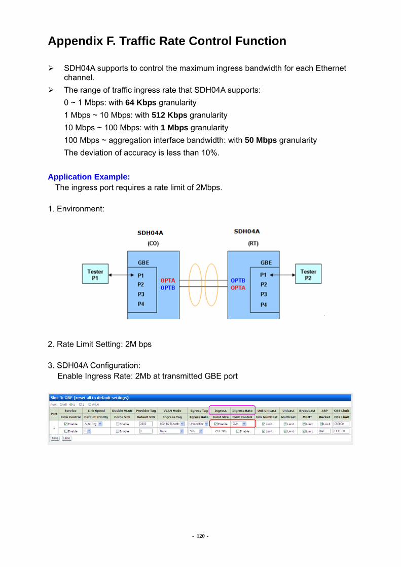
- 120 -
Appendix F. Traffic Rate Control Function
SDH04A supports to control the maximum ingress bandwidth for each Ethernet channel.
The range of traffic ingress rate that SDH04A supports: 0 ~ 1 Mbps: with 64 Kbps granularity 1 Mbps ~ 10 Mbps: with 512 Kbps granularity 10 Mbps ~ 100 Mbps: with 1 Mbps granularity 100 Mbps ~ aggregation interface bandwidth: with 50 Mbps granularity The deviation of accuracy is less than 10%.
Application Example:
The ingress port requires a rate limit of 2Mbps. 1. Environment:
2. Rate Limit Setting: 2M bps 3. SDH04A Configuration:
Enable Ingress Rate: 2Mb at transmitted GBE port
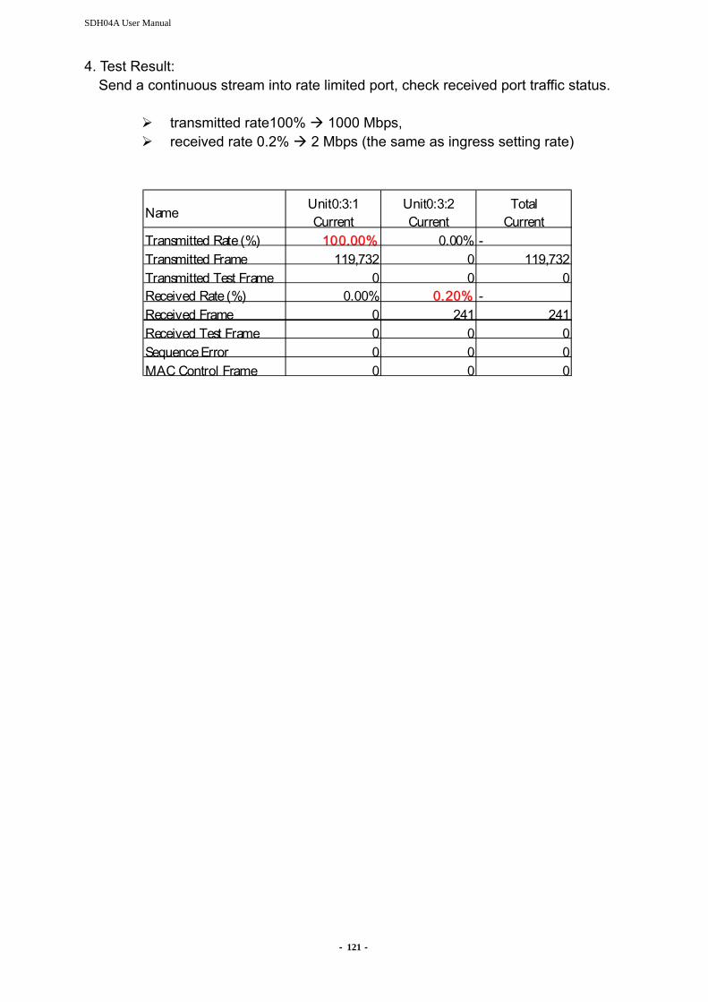
SDH04A User Manual
- 121 -
4. Test Result: Send a continuous stream into rate limited port, check received port traffic status.
transmitted rate100% 1000 Mbps, received rate 0.2% 2 Mbps (the same as ingress setting rate)
Name Unit0:3:1
CurrentUnit0:3:2Current
TotalCurrent
Transmitted Rate (%) 100.00% 0.00% -Transmitted Frame 119,732 0 119,732Transmitted Test Frame 0 0 0Received Rate (%) 0.00% 0.20% -Received Frame 0 241 241Received Test Frame 0 0 0Sequence Error 0 0 0MAC Control Frame 0 0 0

- 122 -
Appendix G. Nx64K Grouping Introduction Nx64 function uses TDM grooming service method and allows user to combine several channels of RT side into one E1 of CO side. Test Scenario Considering two application examples:
Figure1. E1 to V.35
Figure2. E1 to E1
CO side: Slot 2 E1 Tributary Interface RT side: Slot 1 QV35 Tributary Interface or E1 Tributary Interface PS: Nx64 settings are done in RT side only Note: E1 channels in CO side are called ‘Nx64k Group’ and V.35/ E1 channels in RT side are called ‘Subgroups’. If users want to combine 3-V.35 channels from RT side into one E1 channel at CO side (refer to Figure1), and The description of the 3-V.35 channels is:
V35 - Channel 1 uses 7 Time slots. Subgroup 1. From TS = 1 to TS = 7. V35 - Channel 2 uses 5 Time slots. Subgroup 2. From TS = 1 to TS = 5. V35 - Channel 3 uses 9 Time slots. Subgroup 3. From TS = 1 to TS = 9.
Each channel in V.35 forms one Subgroup. (PS: Time slots in V.35 always start
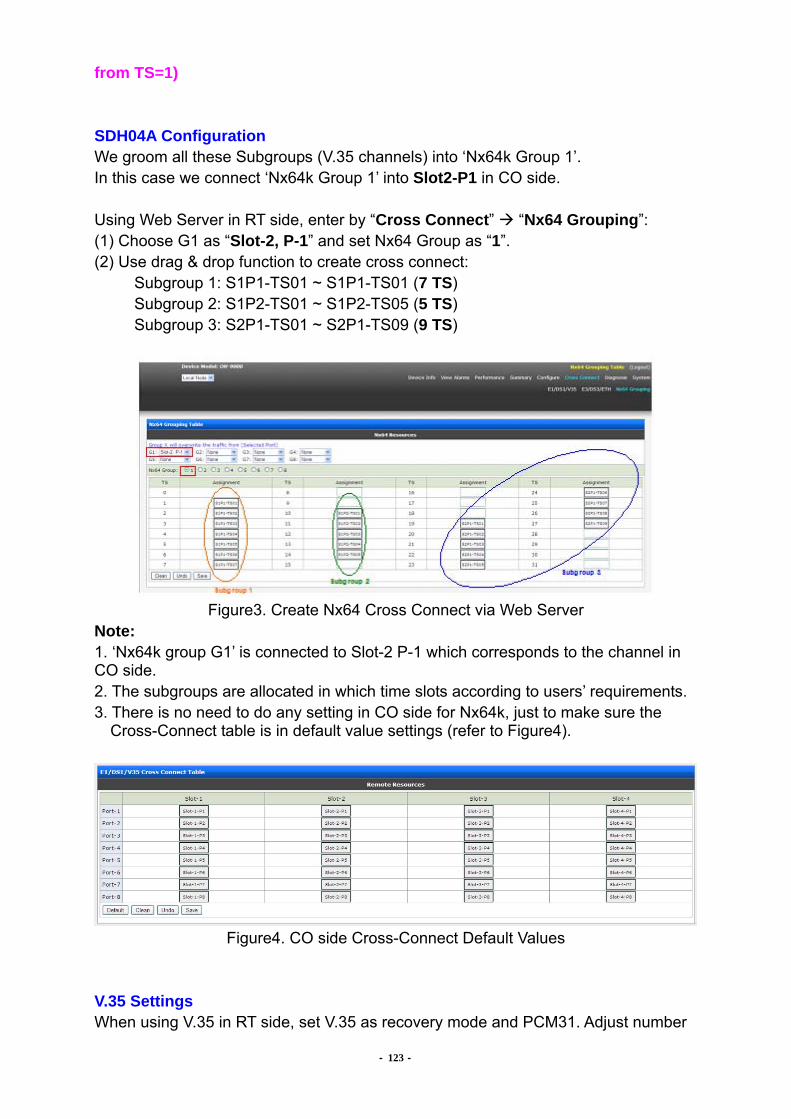
- 123 -
from TS=1) SDH04A Configuration We groom all these Subgroups (V.35 channels) into ‘Nx64k Group 1’. In this case we connect ‘Nx64k Group 1’ into Slot2-P1 in CO side. Using Web Server in RT side, enter by “Cross Connect” “Nx64 Grouping”: (1) Choose G1 as “Slot-2, P-1” and set Nx64 Group as “1”. (2) Use drag & drop function to create cross connect: Subgroup 1: S1P1-TS01 ~ S1P1-TS01 (7 TS) Subgroup 2: S1P2-TS01 ~ S1P2-TS05 (5 TS) Subgroup 3: S2P1-TS01 ~ S2P1-TS09 (9 TS)
Figure3. Create Nx64 Cross Connect via Web Server
Note: 1. ‘Nx64k group G1’ is connected to Slot-2 P-1 which corresponds to the channel in CO side. 2. The subgroups are allocated in which time slots according to users’ requirements. 3. There is no need to do any setting in CO side for Nx64k, just to make sure the
Cross-Connect table is in default value settings (refer to Figure4).
Figure4. CO side Cross-Connect Default Values
V.35 Settings When using V.35 in RT side, set V.35 as recovery mode and PCM31. Adjust number

- 124 -
of Time slots according to users’ requirements. In this test scenario, channel 1 sets 7 time slots, channel 2 sets 5 time slots, and channel 3 sets 9 times slots.
Testing with the E1 Tester: To be able to test this function, it’s required an E1 tester with fractional (Nx64k) E1 capabilities. The unit’s diagnosis function (Embedded PRBS) cannot test this function. By using the E1 tester, it’s only able to test one Subgroup at one time. For our test scenario, Testing Subgroup 1: (1) Connect E1 tester in Slot2 P1 at CO side (2) Set fractional E1 from TS=1 to TS=7 (7 TS) (3) Configure the Clock Mode and Framing settings of V.35 in channel 1 at RT side (4) Set V.35 Terminal Loopback. Traffic should be ok at this moment.
Testing Subgroup 2: (1) Connect E1 tester in Slot2 P1 at CO side (2) Set fractional E1 Slot1 P2 from TS=10 to TS=14 (5 TS) (3) Configure the Clock Mode and Framing settings of V.35 in channel 2 at RT side (4) Set V.35 Terminal Loopback. Traffic should be ok at this moment.
Testing Subgroup 3: (5) Connect E1 tester in Slot2 P1 at CO side (6) Set fractional E1 Slot2 P1 from TS=19 to TS=27 (9 TS) (7) Configure the Clock Mode and Framing settings of V.35 in channel 3 at RT side (8) Set V.35 Terminal Loopback. Traffic should be ok at this moment.

- 125 -
Note: (1) It is also able to use E1 Tributary Interface instead of V35 Tributary Interface. (2) While testing Nx64 function, if user doesn’t want to set “Terminal Loopback”, he
also can use cable to do wire loopback. Synchronization: For Nx64k function, synchronization is very important to work successful. CO side is the master clock always and channels in RT side should always work in recovery mode. Similarly, all Nx64k groups should be synchronized at CO side. Currently, our system has the limitation that the whole synchronization is done according to ‘Nx64k group G1’ from CO side. If ‘Nx64k group G1’ fails, e.g. Loss-of-signal, it will affect traffic in other Nx64k groups. In case ‘Nx64k group G1’ is ok, the whole system is synchronized and won’t be affected by problems in other Nx64 groups. For example, there are three groups, G1, G2, G3. If G1 is ok but G2 fails, G3 won’t be affected, only traffic in G2 won’t work. But if G2 and G3 is ok and G1 fails, traffic in G2, G3 would have problems because the system cannot synchronized. We expect to overcome this restriction for future versions. Limitations in current version:
Synchronization is done from ‘Nx64k group G1’ only. If G1 fails, other Nx64k groups will also fail.
Only 4 Nx64k-groups are supported. G1, G2, G3 and G4. (G5, G6, G7 and G8 can’t use)
V.35 interface or E1 interface used for Nx64k can only be connected in slot 1 or slot 2.
Only one V.35 interface is supported (Slot 1 or Slot 2).
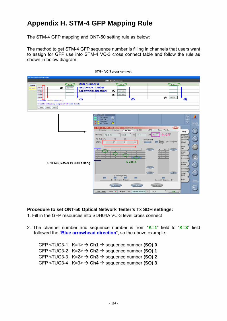
- 126 -
Appendix H. STM-4 GFP Mapping Rule The STM-4 GFP mapping and ONT-50 setting rule as below: The method to get STM-4 GFP sequence number is filling in channels that users want to assign for GFP use into STM-4 VC-3 cross connect table and follow the rule as shown in below diagram.
Procedure to set ONT-50 Optical Network Tester’s Tx SDH settings: 1. Fill in the GFP resources into SDH04A VC-3 level cross connect 2. The channel number and sequence number is from “K=1” field to “K=3” field
followed the “Blue arrowhead direction”, so the above example:
GFP <TUG3-1 , K=1> Ch1 sequence number (SQ) 0 GFP <TUG3-2 , K=2> Ch2 sequence number (SQ) 1 GFP <TUG3-3 , K=2> Ch3 sequence number (SQ) 2 GFP <TUG3-4 , K=3> Ch4 sequence number (SQ) 3
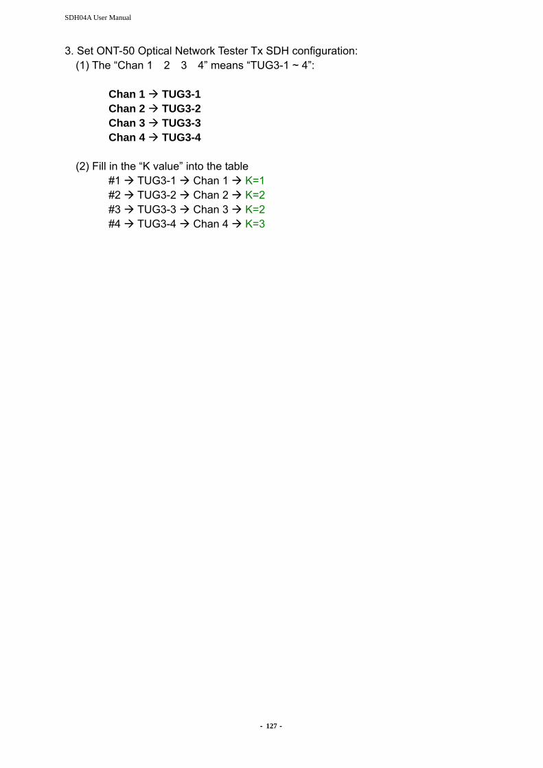
SDH04A User Manual
- 127 -
3. Set ONT-50 Optical Network Tester Tx SDH configuration: (1) The “Chan 1 2 3 4” means “TUG3-1 ~ 4”:
Chan 1 TUG3-1 Chan 2 TUG3-2 Chan 3 TUG3-3 Chan 4 TUG3-4 (2) Fill in the “K value” into the table #1 TUG3-1 Chan 1 K=1 #2 TUG3-2 Chan 2 K=2 #3 TUG3-3 Chan 3 K=2 #4 TUG3-4 Chan 4 K=3
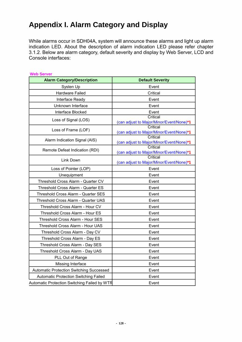
- 128 -
Appendix I. Alarm Category and Display While alarms occur in SDH04A, system will announce these alarms and light up alarm indication LED. About the description of alarm indication LED please refer chapter 3.1.2. Below are alarm category, default severity and display by Web Server, LCD and Console interfaces:
Web ServerAlarm Category/Description Default Severity
Systen Up EventHardware Failed CriticalInterface Ready Event
Unknown Interface EventInterface Blocked Event
Loss of Signal (LOS)Critical
(can adjust to Major/Minor/Event/None)*1
Loss of Frame (LOF)Critical
(can adjust to Major/Minor/Event/None)*1
Alarm Indication Signal (AIS)Critical
(can adjust to Major/Minor/Event/None)*1
Remote Defeat Indication (RDI)Critical
(can adjust to Major/Minor/Event/None)*1
Link DownCritical
(can adjust to Major/Minor/Event/None)*1Loss of Pointer (LOP) Event
Unequipment EventThreshold Cross Alarm - Quarter CV EventThreshold Cross Alarm - Quarter ES Event
Threshold Cross Alarm - Quarter SES EventThreshold Cross Alarm - Quarter UAS Event
Threshold Cross Alarm - Hour CV EventThreshold Cross Alarm - Hour ES Event
Threshold Cross Alarm - Hour SES EventThreshold Cross Alarm - Hour UAS EventThreshold Cross Alarm - Day CV EventThreshold Cross Alarm - Day ES Event
Threshold Cross Alarm - Day SES EventThreshold Cross Alarm - Day UAS Event
PLL Out of Range EventMissing Interface Event
Automatic Protection Switching Successed EventAutomatic Protection Switching Failed Event
Automatic Protection Switching Failed by WTR Event
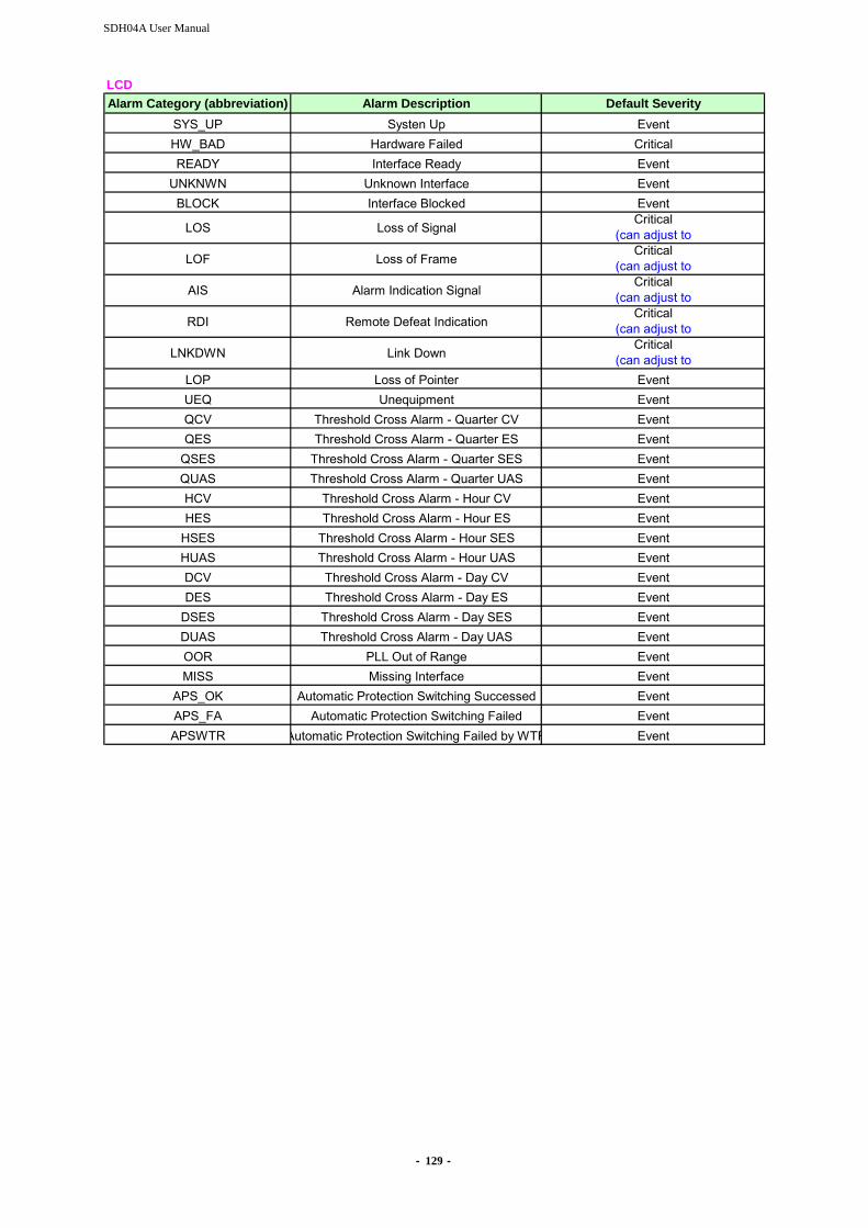
SDH04A User Manual
- 129 -
LCDAlarm Category (abbreviation) Alarm Description Default Severity
SYS_UP Systen Up EventHW_BAD Hardware Failed CriticalREADY Interface Ready Event
UNKNWN Unknown Interface EventBLOCK Interface Blocked Event
LOS Loss of SignalCritical
(can adjust to
LOF Loss of FrameCritical
(can adjust to
AIS Alarm Indication SignalCritical
(can adjust to
RDI Remote Defeat IndicationCritical
(can adjust to
LNKDWN Link DownCritical
(can adjust toLOP Loss of Pointer EventUEQ Unequipment EventQCV Threshold Cross Alarm - Quarter CV EventQES Threshold Cross Alarm - Quarter ES Event
QSES Threshold Cross Alarm - Quarter SES EventQUAS Threshold Cross Alarm - Quarter UAS EventHCV Threshold Cross Alarm - Hour CV EventHES Threshold Cross Alarm - Hour ES Event
HSES Threshold Cross Alarm - Hour SES EventHUAS Threshold Cross Alarm - Hour UAS EventDCV Threshold Cross Alarm - Day CV EventDES Threshold Cross Alarm - Day ES Event
DSES Threshold Cross Alarm - Day SES EventDUAS Threshold Cross Alarm - Day UAS EventOOR PLL Out of Range EventMISS Missing Interface Event
APS_OK Automatic Protection Switching Successed EventAPS_FA Automatic Protection Switching Failed EventAPSWTR Automatic Protection Switching Failed by WTR Event
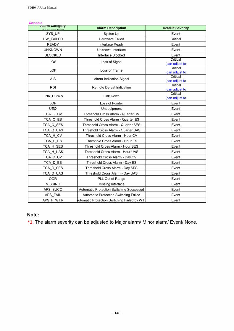
SDH04A User Manual
- 130 -
ConsoleAlarm Category(abbreviation) Alarm Description Default Severity
SYS_UP Systen Up EventHW_FAILED Hardware Failed Critical
READY Interface Ready EventUNKNOWN Unknown Interface EventBLOCKED Interface Blocked Event
LOS Loss of SignalCritical
(can adjust to
LOF Loss of FrameCritical
(can adjust to
AIS Alarm Indication SignalCritical
(can adjust to
RDI Remote Defeat IndicationCritical
(can adjust to
LINK_DOWN Link DownCritical
(can adjust toLOP Loss of Pointer EventUEQ Unequipment Event
TCA_Q_CV Threshold Cross Alarm - Quarter CV EventTCA_Q_ES Threshold Cross Alarm - Quarter ES Event
TCA_Q_SES Threshold Cross Alarm - Quarter SES EventTCA_Q_UAS Threshold Cross Alarm - Quarter UAS EventTCA_H_CV Threshold Cross Alarm - Hour CV EventTCA_H_ES Threshold Cross Alarm - Hour ES Event
TCA_H_SES Threshold Cross Alarm - Hour SES EventTCA_H_UAS Threshold Cross Alarm - Hour UAS EventTCA_D_CV Threshold Cross Alarm - Day CV EventTCA_D_ES Threshold Cross Alarm - Day ES Event
TCA_D_SES Threshold Cross Alarm - Day SES EventTCA_D_UAS Threshold Cross Alarm - Day UAS Event
OOR PLL Out of Range EventMISSING Missing Interface Event
APS_SUCC Automatic Protection Switching Successed EventAPS_FAIL Automatic Protection Switching Failed Event
APS_F_WTR Automatic Protection Switching Failed by WTR Event Note: *1. The alarm severity can be adjusted to Major alarm/ Minor alarm/ Event/ None.


![SonetExpert™ Channelized Analyzer...6 Main Features… •Scans the received STM-4/STM-1 traffic and identifies the mapping, tributary type [T1/E1], equipped/unequipped status of](https://img.dokumen.tips/doc/110x75/5faa757c67d2b2363f7d8338/sonetexperta-channelized-analyzer-6-main-features-ascans-the-received-stm-4stm-1.jpg)