Embed Size (px)
Citation preview
1
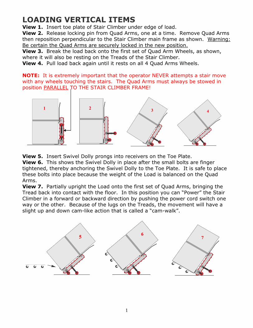
LOADING VERTICAL ITEMS View 1. Insert toe plate of Stair Climber under edge of load.
View 2. Release locking pin from Quad Arms, one at a time. Remove Quad Arms then reposition perpendicular to the Stair Climber main frame as shown. Warning:
Be certain the Quad Arms are securely locked in the new position. View 3. Break the load back onto the first set of Quad Arm Wheels, as shown,
where it will also be resting on the Treads of the Stair Climber. View 4. Pull load back again until it rests on all 4 Quad Arms Wheels.
NOTE: It is extremely important that the operator NEVER attempts a stair move with any wheels touching the stairs. The Quad Arms must always be stowed in
position PARALLEL TO THE STAIR CLIMBER FRAME!
View 5. Insert Swivel Dolly prongs into receivers on the Toe Plate. View 6. This shows the Swivel Dolly in place after the small bolts are finger
tightened, thereby anchoring the Swivel Dolly to the Toe Plate. It is safe to place these bolts into place because the weight of the Load is balanced on the Quad
Arms.
View 7. Partially upright the Load onto the first set of Quad Arms, bringing the Tread back into contact with the floor. In this position you can “Power” the Stair
Climber in a forward or backward direction by pushing the power cord switch one way or the other. Because of the lugs on the Treads, the movement will have a
slight up and down cam-like action that is called a “cam-walk”.

2
VERTICAL STAIR MOVE SEQUENCE
View 8. Once the operator has placed the Stair Climber in a vertical position at
the foot of the stairs, he simply reverses the motor and the load will lean into the stairs and stop.
View 9. Next, the operator gives a slight tug on the safety strap. (The safety strap is attached to the ratcheted strap that secures the load to the Step Rider.
The safety strap is then brought up over the top of the load so that the operator may hold it as he does the move. The strap does not show in drawing.) The entire
load will lay itself gently onto the stairs and the operator can begin the stair climb.
Views 10 and 11. As the operator reaches the top of the stairs he will begin to
balance the load so that the nose does not dip down toward the stairs.

3
Views 12, 13 and 14. Here the operator must nose the load up slightly and maintain the balance as he “cam-walks” the load onto the landing. This is easy
to do; there is practically no weight on the operator. The gentle “cam-walk” action makes a slight up and down movement, and the operator should continue
the “cam-walk” until he feels 5 of those movements.
View 15. The operator up-rights the load onto the first row of casters ONLY,
because the rest of the Swivel Dolly is still hanging out over the staircase. If the operator feels more secure, and has the space, he can continue the “cam-walk”
until the entire Swivel Dolly is above the landing before up-righting the unit.
View 16. Here, the operator has completely up-righted the load, which is back
in a vertical position and resting on the Swivel Dolly. It can then be rolled to its final placement position, or placed at the foot of the next flight of stairs.

4
LOADING LONG HORIZONTAL ITEMS
View 1. For loads that are longer than the Stair Climber, use a loading ramp
that then becomes a platform for the load to rest upon during the move. This view shows the Stair Climber resting on the lower part of the Angle Dolly,
thereby tilting the loading ramp for ease in loading. (The Ramp Board is not
shown in this drawing.)
View 2. Notice the wooden block in front of the load. This was done to
adjust the center of gravity. Depending on the weight distribution in the load
being moved, the operator may add more blocks or may not need any.
View 3. Here the stair climber is flat on the floor after having crawled down
from the Angle Dolly.

5
HORIZONTAL STAIR MOVE SEQUENCE
View 4. With the load securely strapped to the Stair Climber, position the Ramp Plate on the Angle Dolly, and then crawl the Stair Climber onto the Angle
Dolly.
View 5. Here the Stair climber is positioned perfectly.
View 6. Roll the load to the foot of the stairs and place the narrow end of the Ramp Plate in the slot at the top end of the Angle Dolly, and rest the top
of the Ramp Plate on the step as shown.

6
View 7. Crawl the load up onto the Ramp Plate.
View 8. Crawl the load from the ramp plate onto the stairs.
View 9. Continue the climb until your reach the top of the stairs.
7
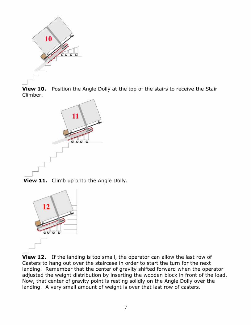
View 10. Position the Angle Dolly at the top of the stairs to receive the Stair
Climber.
View 11. Climb up onto the Angle Dolly.
View 12. If the landing is too small, the operator can allow the last row of
Casters to hang out over the staircase in order to start the turn for the next landing. Remember that the center of gravity shifted forward when the operator
adjusted the weight distribution by inserting the wooden block in front of the load. Now, that center of gravity point is resting solidly on the Angle Dolly over the
landing. A very small amount of weight is over that last row of casters.

8
OPERATION USING ALTERNATING CURRENT (AC)
AND DIRECT CURRENT (DC)
CHARGER
PLUG
+ -
+ - BATTERY
+ - BATTERY
INVERTER DC- BOX -
YELLOW TO WHITE
BLACK TO BLACK
RED TO RED
WHITE TO ORANGE
SWITCH
MALE PLUG
FEMALE PLUG
MALE PLUG
TO BOX
GROUND TO FRAME & MOTOR
MOTOR
MALE PLUG
Operation using AC only. (1) Make sure the Inverter Switch is in off
positon. (2) Plug the male end of the power cord into an extension
cord and then into wall socket.
Operation using DC only. (1) Turn
Power Inverter Switch to “ON” position. (2) Plug the male and
female ends together.
Note: EXTENSION CORD MUST BE 16 GA. OR HEAVIER.
Male Plug Female Plug
OPERATE POWER INVERTER To Operate the Power Inverter for DC power, turn switch ON as shown below. Leave switch in OFF
position for AC power use, when CHARGING BATTERIES, and when machine is NOT IN USE.
DO NOT LEAVE SWITCH ON WHEN STORING MACHINE.
Red Fault LED Indicator will come on if battery is low. The inverter may make a loud
ringing sound. Green power LED Indicator means you have power to the Inverter and it is working.
SWITCH
This machine is equipped with a simple
toggle switch for forward and reverse operation. It
automatically returns to NEUTRAL when operator
releases it.
Do not reverse the motor instantly from one
direction to the other; allow a moment for the motor to
rest before changing its direction.
Failure to do this will result in severe arcing and may
burn the contacts of the reversing switch and motor.
POWER CORD Switch Power Cord should be pulled through the
rectangular hole on side of the Step Rider frame, to
whichever side is convenient, for control of the job at
hand.
Note: Keep power cord and extension cord out from
under the treads of the Step Rider, You will cut or pull
the cord off the unit.
Green Power LED
Red Fault LED
ON / OFF Power Switch
9
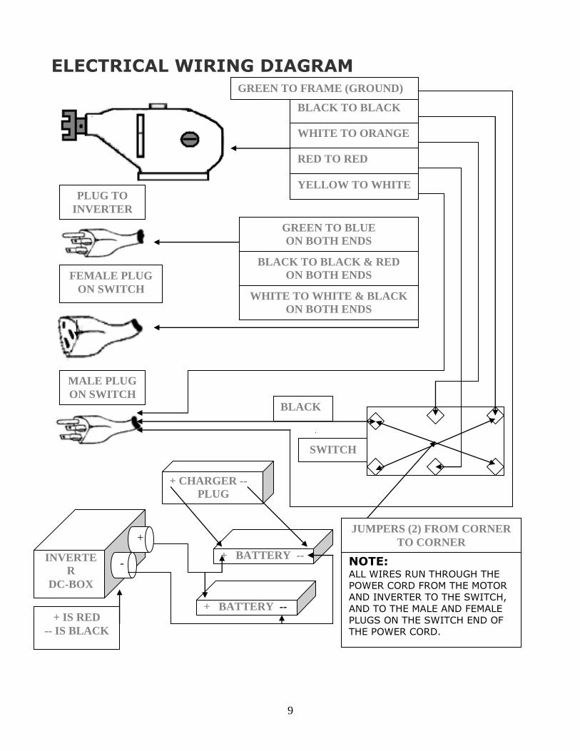
ELECTRICAL WIRING DIAGRAM
YELLOW TO WHITE
BLACK TO BLACK
RED TO RED
WHITE TO ORANGE
INVERTE
R
DC-BOX
PLUG TO
INVERTER
GREEN TO BLUE
ON BOTH ENDS
WHITE TO WHITE & BLACK
ON BOTH ENDS
BLACK TO BLACK & RED
ON BOTH ENDS
GREEN TO FRAME (GROUND)
FEMALE PLUG
ON SWITCH
MALE PLUG
ON SWITCH
BLACK
+ CHARGER --
PLUG
+
- + BATTERY --
+ BATTERY -- + IS RED
-- IS BLACK
SWITCH
NOTE: ALL WIRES RUN THROUGH THE
POWER CORD FROM THE MOTOR
AND INVERTER TO THE SWITCH,
AND TO THE MALE AND FEMALE
PLUGS ON THE SWITCH END OF
THE POWER CORD.
JUMPERS (2) FROM CORNER
TO CORNER

10
MAINTENANCE AND SERVICE
MUD and dirt can accumulate on the inside of the
treads, and may pack hard in the splines of the pulley.
It is possible, though highly unlikely, that the build up
would force the tread off the sprocket.
Occasionally inspect the pulleys and treads for the
condition. If the tread walks off the pulley this may
cause the tread to be cut on the pulley edge, or to
stretch. If this occurs you may have to replace the
treads.
THE GEAR BOX REDUCER has been
properly lubed at the factory. It should need
attention only if there are signs of excessive oil
leakage.
To add oil, remove the fill plug and the level
plug on the side of the gearbox housing.
Pour oil in the fill hole until it runs out of the
level hole. Then replace both plugs.
UNIVERSAL COUPLINGS- Check occasionally
to maintain tightness of all Allen screws.
Two Allen screws are in each thread hole so you
must remove the top locking screw to tighten the
bottom one, on both the MOTOR and GEAR
REDUCER.
ELECTRICAL MOTOR SPECIFICATIONS- The power source for the Step Rider is a
heavy duty motor, 115v., and 7amps ½ H.P., speed 450 R.P.M. no load, and 425 R.P.M.
loaded. Motor Brushes may be checked every year.

11
OPERATION IN PRESENCE OF WATER, MUD, OIL. Remember that the STEP RIDER Motor and DC Power Inverter are electrical and
will short out if they get wet. (Do not run unit through puddles of water, mud, or oil, as this will void
your WARRANTY.)
Grounding Instructions. For your protection this machine is equipped with a 3-conductor cord and
approved 3-blade grounding type plug in accordance with the National Electrical Code. Your extension cord also must have a grounding type connector.
NOTE: EXTENSION CORD MUST BE 16 GA. OR HEAVIER.
Ventilation. Keep motor housing passages clear for cool running motor.
Accumulated dust may be blown out of the motor with an air jet.
Bearings. All Bearings are sealed with lifetime lubrication.
Specifications for base unit
Base unit weight 148 lbs.
Base unit size 42”H x 25” W x 14” D.
Base unit size 80”H x 25” W x 14” D. with handle extended.
Power supply AC115v. DC12v.with two18 amp. Batteries.
Gear box-continuous duty worm gear.
Motor continuous duty ½ horse.
Tread dimensions 84”x 4”x 1.5”
Tread material one piece polyurethane & Kevlar.
Mainframe material one-piece cast aluminum.
Load spreads on stairs over 3 to 4 steps with 6 contact points
that are 4” wide (the width of the tread). Heavy-duty steel toe plate.
Heavy-duty cast aluminum front support.
Heavy-duty 6’’ transport wheels.
Heavy-duty steel handle (Not Designed for break back).
NOTE: New Models come equipped with a one-piece "rack" which replaces the toe plate, and front support. (Not pictured.)
12
WARNINGS: Only persons who have read the Operations Manual and have
viewed the training video should operate this equipment. It is essential that the stairs are clear while machine is being
operated. (No one should be on the stairs below the load) It is imperative that the lugs on the treads line up with the top edge
of the landing before descending the Stairs. (The video shows this in detail.) Always make sure the Step Rider’s Power Inverter is turned off
when not in use. Never use the machine in a way it is not designed for.
Always disconnect the electrical supply due to the hazard of
electricity. The Step Rider Machine requires a Two Man Team at all times, one
to operate and the other to assist. NOTE: It is extremely important that the operator NEVER attempts a stair move with any wheels touching the stairs. The Quad Arms must always be stowed in
position PARALLEL TO THE STAIR CLIMBER FRAME!
SPECIFICATIONS: MAXIMUM LIFT FOR STAIR MOVING Model 1800 Vertical Stair Climbing Maximum Lift is 1800 lbs.
Model 1800 Horizontal Stair Climbing Maximum Lift is 2400 lbs.
Model 3000 Vertical Stair Climbing Maximum Lift is 2400 lbs.
Model 3000 Horizontal Stair Climbing Maximum Lift is 2750 lbs.
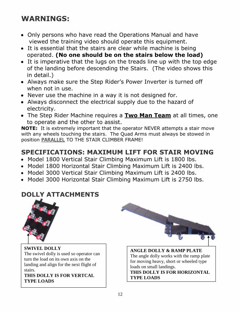
DOLLY ATTACHMENTS
SWIVEL DOLLY
The swivel dolly is used so operator can
turn the load on its own axis on the
landing and align for the next flight of
stairs.
THIS DOLLY IS FOR VERTCAL
TYPE LOADS
ANGLE DOLLY & RAMP PLATE
The angle dolly works with the ramp plate
for moving heavy, short or wheeled type
loads on small landings.
THIS DOLLY IS FOR HORIZONTAL
TYPE LOADS
13
WARRANTY FOR ALL MODEL STAIR CLIMBERS
We warrant each machine to be free from defects in materials and workmanship under normal conditions of use and service for a period of five years Our obligation under this warranty is limited to making good at our factory any part (except treads, power cord and switch, on which our warranty is limited to 90 days, and also except swivel casters which have a 30 day warranty) which, within five years after delivery to the original purchaser, is returned to our factory with transportation charges prepaid, and which our examination shows to our satisfaction to be defective. Shipment to us must be made under a Returned Goods Authorization (RGA) number and such number shall be obtained from us prior to any shipment to us. We expressly deny any power or authority on the part of any person to incur or assume for us any liability in connection with the sale of any machine manufactured by us. This Warranty shall not apply to any machine, which has been repaired or altered outside our factory. Nor shall it apply to any machine, which has been subject to misuse, negligence or accident, or has been operated contrary to our instructions. Under no circumstances shall we be liable for any consequential damages or any losses or damages resulting from a defect of the machine. We make no warranty whatsoever in respect to accessories attached to our machines which have been made by other manufacturers whether or not warranted by such other manufacturers. This Warrant is made in lieu of all other warranties, express or implied.