Embed Size (px)
Citation preview

Proceedings of the 1st International and 16th National Conference on Machines and Mechanisms (iNaCoMM2013), IIT Roorkee, India, Dec 18-20 2013
Steering Linkage Optimization of Articulated Construction Equipment
Bharath Kumar Somi Thulasiraman, B.E., M.Sc. Product Development Centre
Larsen & Toubro – Machinery Industrial Products Coimbatore, India
Narayana Govindarao Sadali, M.E. Product Development Centre
Larsen & Toubro – Machinery Industrial Products Coimbatore, India
Gomathinayagam Arumugam, M.E. Product Development Centre
Larsen & Toubro – Machinery Industrial Products Coimbatore, India
Igneshwaran Neelamegan, B.E. Product Development Centre
Larsen & Toubro – Machinery Industrial Products Coimbatore, India
Abstract—Articulated vehicles of Earthmoving equipment are steered using hydraulic cylinders mounted between the front and rear frames. Mounting position and location of the cylinders play an important role in uniform stress distribution in frame/chassis, cylinder pressure and stroke Optimization, there by influencing on the power required to steer. By reducing the steering forces, stresses induced in the structures are reduced, facilitating the improved life of the structures. This paper reviews the literature in the subject area, total work done to steer the equipment is calculated, thereby finding the steering pressure and forces. Optimization of mounting points is discussed using the optimization tool available in CAD package and validated experimentally.
Keywords—Articulated vehicle, Optimization, Construction equipment, Steering, Mounting point, Steering force, Steering pressure, Optimized mounting point, Steering cylinder, Earthmoving equipment, Stroke length, Articulation angle.
I. INTRODUCTION
Earth moving equipment is primarily used for tasks in earthwork, compaction and re-handling. The majority of the earth moving equipment’s are articulated vehicles. Fig. 1 shows a typical Wheel Loader, which is a construction equipment used for moving material from one place to another place of a worksite, dumper, railway wagon or a hopper. It consists of a front frame and a rear frame connected through a pin joint for articulation. Rear frame consists of the power train like Engine, Transmission & rear axle, Hydraulic systems like pump and valves, Operator Cab with controls for the machine operation & lights and Counterweight.
According to the dictionary articulated means jointed or segmented. This definition agrees well with the common impression of an articulated vehicle. Such a
Fig. 1 - Wheel Loader
Bucket Linkage
Bucket Cylinder
Operator cabin Engine Hood
Wheel Assembly
Front frame Rear frame
404

Proceedings of the 1st International and 16th National Conference on Machines and Mechanisms (iNaCoMM2013), IIT Roorkee, India, Dec 18-20 2013
vehicle consists of two or more body or frame units jointed together. These units or sections should be an integral part of the vehicle. The joints may have one, two or three degrees of freedom (yaw, pitch and roll) [1,2]. All wheels are usually driven during off-the-road operation [3,4]. It might seem trivial to state this definition, but surprisingly enough, in the literature searched by the author, an accurate definition of an articulated vehicle was nowhere to be found. An attempt [3] has been made to give a relatively complete picture of articulated steering vehicles in off-road applications where he stated the advantages of articulated steering. In references [5] & [6] systematic classification of design and operating parameters are discussed, typical to steering systems of mobile earthmoving equipment, in respect of various steering gears and the main elements of a steering unit. In comparison to earthmoving equipment with articulated frame steering, equipment with single-axle steering and identical undercarriage geometry has the significant disadvantage that it is considerably less flexible and maneuverable and thus possesses lower performance capability [5].
In this paper, total work required to articulate the equipment is derived. Also the methodology to optimize the steering pressure and steering force, has been discussed by moving the steering cylinder mounting points by using the CAD package called Pro/Engineer. Results obtained through this methodology are verified experimentally by mapping the pressure with the help of “Data Logger” and the pressure values are analyzed.
II. ANALYTICAL METHODOLOGY
The model of an articulated earth moving vehicle in straight and steered conditions is shown in Fig. 2. It is generally assumed that the front or rear structure with less reaction starts to steer initially [7]. Steering cylinders used to steer the machine has its mounting both on front chassis and rear chassis, these mounting points determine the steering pressure and force required for articulation.
Fig. 2 - Articulated earth moving equipment in straight & steered condition
For calculating the steering pressure, it’s assumed that the tire patch shape to be a circle and the patch area is calculated by equating tire inflation pressure with the normal force acting on the area, during empty vehicle steering, the load on the front axle will be less than that of the rear axle and in the case of Laden vehicle steering rear axle load will be more than front axle. So, the articulation joint can be assumed to be moving in a straight line [6]. During steering, one cylinder extends and another cylinder retracts. The force acts on the bore side and the rod side in the extension and retraction cylinders respectively [7]. The effect of a turning mechanism, with the machine at a standstill, causes the centers of wheel tracks which move along curved trajectories to come closer, the wheels on one side of the machine generally moving in opposite directions so that the outer wheels move apart and the inner wheels come closer together [8].
Fig. 3 – Machine in Articulated Condition
Fig. 3 shows the machine in articulated condition. The operating parameters used for Optimization methodology in the CAD tool are shown in TABLE 1. Fig. 4 indicates the existing mounting points of the steering cylinders.
TABLE 1 - OPERATING PARAMETERS
Parameter Value Unit
α ± 40 deg
WT 11500 kgf
WF 10486 kgf
WR 4514 kgf
db 75 mm
dr 45 mm
CS 0.8 --
CR 0.018 --
PRF 50 psi
PRR 50 psi
405

Proceedings of the 1st International and 16th National Conference on Machines and Mechanisms (iNaCoMM2013), IIT Roorkee, India, Dec 18-20 2013
Fig. 4 - Mounting Points
In Fig. 5, red lines shows the machine in the straight
condition and dotted green line shows the machine in articulated condition. During articulation, the machine has to overcome three resistances [9] due to: • Wheel Alignment • Wheel Rolling • Wheel Dragging
A. Work done for Wheel Alignment (WA)
Since axle doesn’t have stub pin, wheel will not align independently. Aligning will happen if the moment overcomes tire to ground friction [6].
From Fig. 6, considering the profile as parabola the equation becomes
p=ar2+br+c...…………………….. (1)
For a given Parabola, a, b, c are constants, p, pressure and r, radius of the Tire patch area.
For r=0, p is maximum dpdr=0,
d2p
dr2<0
yields��� 2ar+b=0,
Sub r= 0 yields��� b=0,
Sub b=0 in �1� yields��� p=ar2+c, d2p
dr2=2a<0
yields��� a is negative
For r=R, p=0,
yields��� aR2+c�0,
c=-aR2,
A = 843 mm B = 604 mm C = -69.5 mm D = 498 mm
A
B
C
D
Fig. 5 - Wheel Position at steered condition
406

Proceedings of the 1st International and 16th National Conference on Machines and Mechanisms (iNaCoMM2013), IIT Roorkee, India, Dec 18-20 2013
Fig. 6 - Pressure Profile of tyre
Equation �1�becomes p=ar2-aR2,
Reversingthesignofa,
p=a�R2-r2�, then a becomes positive…………………(2)
Force Supported by annular area: f=p·2πr·dr,
Force over entire area
F=� p·2πr·dr
R
0
………………………………….(3)
By simplifying Equation�3�,we get
F=π·a·R4
2
a=2F
πR4
p=2F
πR4�R2-r2�
pmax=2F
πR2
assumingp
max is twice the average pressure
Average pressure pa=F
πR2
Moment caused by annular area
M=Tangent force x radius
M=p·2πrdr·Cs.r=2π·CS·p·r
2·dr
M=2π·CS·2F
πR4·�R2-r2�·r2·dr
Total Moment,
M=4FCS
R4��R2r2-r4�R
0
dr
M=4FCS
R4�R2r3
3-r5
5�0
R
M=4FCS
R4�R5
3-R5
5�
M=4FCS
R4·2
15·R5
M=8FCsR
15
M=0.5333·F·Cs·R
Considering constant pressure, p=F
πR2
M=2πCS·F
πR2·r2·dr
M=2FCS
R2� r2dr
R
0
M=2FCS
R2· �R3
3�
M=2
3·FCSR
M=0.6667FCSR
where, F=Machine front or rear Weight�WF or WR� R=Radius offront or rear wheel patch �RForRR� CS=Coefficient of friction Sliding
Total moment is caused by both Front and Rear Tires, so the Work done required for wheel Alignment is,
WA�α�=0.6667·CS·α·[�WF·RF�+�WR·RR�]
B. Work done for rolling of wheel (WRO)
During articulation the outer and inner wheel has to roll to some specific distance to cover the required articulation angle work done to cover the distance can be calculated using the below equation. Work done for Rolling of the Wheel,
WRO=WOW+WIW
WOW= DO·CR·WT
2; W
IW=DI·CR·WT
2
p=ar2+br+c
407

Proceedings of the 1st International and 16th National Conference on Machines and Mechanisms (iNaCoMM2013), IIT Roorkee, India, Dec 18-20 2013
Where, DO �Distance travelled by outer wheels CR �Coefficient of friction rolling DI �Distance travelled by inner wheels
C. Work done for Dragging of wheel (WD)
Before rolling takes place, the center point of the axle is dragged during articulation. Work done during dragging can be calculated from the following equation: Work done for Dragging of the Wheel,
WD=DD·WT·CS
Where, DD � Distancetravelledbydragging
Dimensions of DI, Do, DD can be determined by creating sketch in CAD package and the values can be taken for calculating Work done.
D. Total Work done to steer (WDS)
Total work done for articulating the machine can be calculated by summing up the work done for aligning, dragging & rolling. Total Work done required to steer the Wheel,
WDS=WA+WRO+WD
E. Pressure required at steering cylinders (PS)
Cylinder pressure determines the strength of the structure and the pump selection hence it has to be optimized. Pressure required at steering cylinders for the total work done can be given by:
Total workdone,PS= WDS
SI·AR+SO·AB
Where,
SI=D1-DI; SO=DO-D1 AR = π(db
2- dr2) / 4AB = πdb
2 / 4
Fig. 7 - Steering Cylinders in straightcondition
F. Stroke length of the cylinder (SC)
Cylinder stroke length is an important parameter, since the increase in stroke length will reduce the pressure
but cost of the cylinder will become high. Hence this is also one of the parameter to be optimized. Stroke Length of the Steering Cylinder,
SC=DO–DI Where, DO-Openlengthofthecylinder DI-Closedlengthofthecylinder
G. Steering forces on the cylinders (FR & FB)
With respect to steering pressure and stroke length, steering force is calculated. Steering force determines the rigidity and fatigue life of the structure. Steering force is directly proportional to steering pressure; hence by reducing the steering pressure, steering force can be reduced.
FB=p.ABF�=p.AR
III. OPTIMIZATION OF MOUNTING POINTS TO REDUCE
STEERING PRESSURE
The above parameters need to be optimized to reduce the steering force, so that the structure life will be increased. Before optimizing the given variables & constraints, linkage need to be checked for the feasibility of the steering linkage, because, the optimization tool will only consider the possibility to get the most optimized points and not the feasibility of the linkage.
Fig. 8 - Steering Cylinders in articulated condition
Fig. 7 shows the free body sketch of the steering mounting points at straight condition of the machine. Where, D1 is the Length of the both cylinders in straight condition. Fig. 8 shows the steering cylinder’s position at fully steered condition of the machine, where we can see that the outer cylinder length is the open length (DO) of the both cylinders and the Inner cylinder length is the closed length (DI) of the both cylinders.
Design constraints - Pressure & Stroke length
Design Variable–A, B, C & D (Cylinder Mounting Points)
408
Proceedings of the 1st International and 16th National Conference on Machines and Mechanisms (iNaCoMM2013), IIT Roorkee, India, Dec 18-20 2013
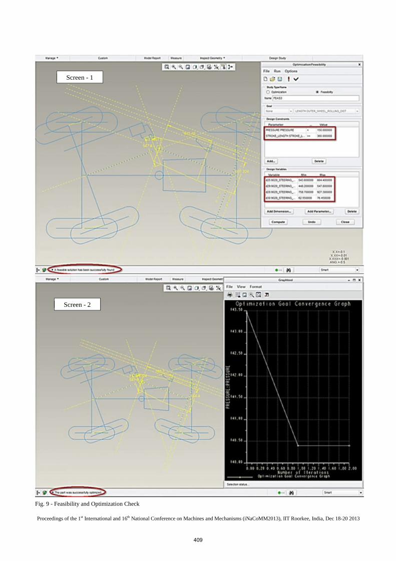
Fig. 9 - Feasibility and Optimization Check
Screen - 1
Screen - 2
409
Proceedings of the 1st International and 16th National Conference on Machines and Mechanisms (iNaCoMM2013), IIT Roorkee, India, Dec 18-20 2013
A. Feasibility Check
In Fig. 9 screen-1, snap of feasibility check for new mounting point has been shown from the CAD package. By running the various combinations for the given variables, the soft tool will tell whether the linkage is possible to work in the given design constraints. If it’s not feasible, minimum and maximum values in the variable can be changed, to get the feasible steering mounting points.
B. Optimization Check
Major difference between the feasibility and optimization is that in feasibility study, whether the system will work in the given range can be found out, whereas in optimization study, optimized solution can be arrived for our required goal. Feasibility check is a must one, before doing optimization. In Fig. 9 screen-2, the linkage has been optimized to reduce the pressure; graph shows the pressure has been reduced from 143bar to 141bar in 3 iterations using the CAD tool.
IV. RESULTS & DISCUSSION
From TABLE 2, it is noted that steering pressure has been reduced by 17bar and relatively the steering force has also been reduced. Optimized Mounting Points of steering cylinders are A = 866 mm, B = 586 mm, C = -45 mm and D = 554 mm.
TABLE 2 - DESIGN OUTPUTS FOR EXISTING AND NEW OPTIMIZED MOUNTING POINTS
Parameters Existing optimized
Steering pressure (Bar) 158 141
Stroke Length (mm) 328 360
Steering force Bore end (kgf) 7111 6346
Steering force Rod end (kgf) 2566 4061
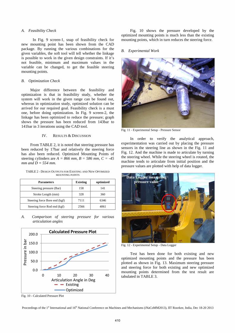
A. Comparison of steering pressure for various articulation angles
Fig. 10 - Calculated Pressure Plot
Fig. 10 shows the pressure developed by the optimized mounting points is much less than the existing mounting points, which in turn reduces the steering force.
B. Experimental Work
Fig. 11 - Experimental Setup - Pressure Sensor
In order to verify the analytical approach,
experimentation was carried out by placing the pressure sensors in the steering line as shown in the Fig. 11 and Fig. 12. And the machine is made to articulate by turning the steering wheel. While the steering wheel is rotated, the machine tends to articulate from initial position and the pressure values are plotted with help of data logger.
Fig. 12 - Experimental Setup - Data Logger
Test has been done for both existing and new
optimized mounting points and the pressure has been plotted as shown in Fig. 13. Maximum steering pressure and steering force for both existing and new optimized mounting points determined from the test result are tabulated in TABLE 3.
0.0
50.0
100.0
150.0
200.0
0 10 20 30 40
Pre
ssu
re
in b
ar
Articulation Angle in Deg
Calculated Pressure Plot
Existing
Optimized
Data Logger measuring pressure value
410

Proceedings of the 1st International and 16th National Conference on Machines and Mechanisms (iNaCoMM2013), IIT Roorkee, India, Dec 18-20 2013
Fig. 13 - Experimental Pressure Plot
TABLE 3 - TEST VALUES FOR EXISTING AND OPTIMIZED MOUNTING POINTS
Parameters Existing Optimized
Steering pressure (Bar) 140 125
Stroke Length (mm) 328 360
Steering force Bore end (kgf) 6301 5626
Steering force Rod end (kgf) 4033 3600
V. CONCLUSION
The analytical methodology is developed to optimize the steering pressure and force to reduce the shock loads coming on to structure of the articulated earth moving equipment. The analytical approach is verified using Experiments conducted in the laboratory and field for both existing mounting points and new optimized mounting points. It is found that by optimizing the mounting points, stresses on the mounting points are reduced increasing the life of structures. Hence the developed methodology shall be used to optimize steering pressure and force in a similar kind of applications in order to design the structure to overcome failures.
ACKNOWLEDGMENTS
The authors thank the management of Larsen & Toubro for the use of their articulated earth moving vehicle data and granting permission to publish this article and also thank Mr. Kasilingam Arumugam, Mr. Boopathy Kumar Mani and other colleagues for their assistance and support in carrying out this research.
NOMENCLATURE
Α Articulation or Steering angle WA Work done required for aligning the Wheel WA (α) Work done required for aligning the Wheel at an
articulated angle �α� WT Total Machine Weight payload WF Machine Front Laden Weight
WR Machine Rear Laden Weight db Bore diameter of steering cylinder dr Rod diameter steering cylinder CS Coefficient of friction Sliding CR Coefficient of friction rolling PRF Front tyre Pressure PRR Rear tyre Pressure p Constant pressure F Machine front Weight (WF) or Machine Rear
Weight (WR) RF Radius of front wheel patch Area RR Radius of rear wheel patch Area WOW Work done by outer wheels WIW Work done by inner wheels D1 Steering Cylinder Lengths at Machine Straight
Condition DO Open length of the cylinder DI Closed length of the cylinder DO Distance travelled by outer wheels DI Distance travelled by inner wheels DD Distance travelled during dragging SI Stroke of the inner cylinder SO Stroke of the outer cylinder Sc Stroke Length of the Steering Cylinder required
to articulate the machine AR Area of Rod end AB Area of Bore end FB Force acting on the bore side of the Steering
cylinder FR Force acting on the rod side of the Steering
cylinder
REFERENCES [1] D-H Wu, "A theoretical study of the yaw/roll motions of a multiple
steering articulated vehicle," in Proceedings of the Institution of Mechanical Engineers, Part D: Journal of Automobile Engineering, Great Britain, 2001, pp. 1257-1265.
[2] A J P Miège and D Cebon, "Active roll control of an experimental articulated vehicle," in Proceedings of the Institution of Mechanical Engineers, Part D: Journal of Automobile Engineering, Great Britain, 2005, pp. 791-806.I.S. Jacobs and C.P. Bean.
[3] I.C Holm, "Articulated, Wheeled Off-the-road Vehicles," Journal of Terramechanics, vol. 7, no. 1, p. 19 to 54, 1970.
[4] M.G. Bekker, Title of Land Locomation. Michigan: The University of Michigan Press, 1956.
[5] Piotr A. Dudzinski, "Design Characteristics of Steering Systems For Mobile Wheeled Earthmoving Equipment," Journal of Terramechanics, vol. 26, no. 1, pp. 25-82, 1989.
[6] Piotr A.Dudzinski, "Problems of Turning Process in Articulated Terrain Vehicles," Journal of Terramechanics, vol. 19, no. 4, pp. 243-256, 1983.
[7] A. Gomathinayagam, B. Raghuvarman, S. Babu, and K. Mohamed Rasik Habeeb, "Prediction of Shock Load due to Stopper Hitting During Steering in an Articulated Earth Moving Equipment," in Lecture Notes in Mechanical Engineering, 2013, pp. 1051-1021
[8] J. Zieba P. Dudzinski, "Studies of turning kinematics of an articulated vehicle," Technical University of Worclaw, Worclaw, 1973
[9] Thomas D.Gillespie, Fundamentals of Vehicle Dynamics. Warrendale: SAE.
0.0
50.0
100.0
150.0
0 12 22 32
Pre
ssu
re
in b
ar
Articulation Angle in deg
Experimental Pressure plot
Existing
Optimized
411