Embed Size (px)
Citation preview


Steel Roof DeckRD - 2010 Standard for
AmericAn nAtionAl stAndArds institute/ steel deck instituteSTEEL DECKINSTITUTE
s ®
1. General
1.1 Scope:A. This Standard for Steel Roof Deck, hereaf ter referred to as the Standard, shall govern
the materials, design, and erection of cold formed steel deck used for roof applications in buildings and similar structures.
B. The user notes shall not be part of the Standard.
User Note: User notes are intended to provide practical guidance in the use and application of this Standard.
C. Where the Standard refers to “designer,” this shall mean the entity that is responsibleto the Owner for the overall structural design of the project, including the steel deck.This is usually the Structural Engineer of Record.
D. Equations that appear in this Standard are compatiblewith the inch-pounds system ofunits. However, any consistent system of units may be used. SI units or equations are shown in parenthesis in this Standard are for information only and are not part of this Standard.
E. Terms not defined in this Standard, AISI S100 or AISI/AISC shall have the ordinary accepted meaning for the context for which they are intended.
F. It shall be permitted to specify deck base steel thickness either by dimensionalthickness, or by gage when the relationship of base steel thickness to gage has been defined by the deck manufacturer. However, for the purpose of design, the dimensional thickness shall be used.
1.2 Reference Codes, Standards, and Documents:A. Codes and Standards: The following documents or portions thereof are referenced in
this Standard and shall be considered part of the requirements of this Standard. 1. American Iron and Steel Institute (AISI) a. AISI S100-07 w/S2-10, North American Specification for the Design
of Cold-Formed Steel Structural Members, Including Supplement 2 (February 2010)
b. AISI S905-08, Test Methods for Mechanically Fastened Cold-FormedSteel Connections
c. AISI S907-08, Test Standard for Cantilever Test Method for Cold-Formed Steel Diaphragms
d. AISI/AISC, Standard Definitions for Use in the Design of Steel Structures, 2007 edition
2. American Welding Society (AWS) a. AWS D1.3:2008, Structural Welding Code-Sheet Steel 3. American Society for Testing and Materials (ASTM) a. ASTM A653 / A653M - 08 Standard Specification for Steel Sheet,
Zinc-Coated (Galvanized) or Zinc-Iron Alloy-Coated (Galvannealed) by the Hot-Dip Process
b. ASTM A1008 / A1008M - 08a, Standard Specification for Steel, Sheet, Cold-Rolled, Carbon, Structural, High-Strength Low-Alloy, High-Strength Low-Alloy with Improved Formability, Solution Hardened, and Bake Hardenable
1

Steel Roof DeckRD - 2010 Standard for
AmericAn nAtionAl stAndArds institute/ steel deck instituteSTEEL DECKINSTITUTE
s ®
4. American Society of Civil Engineers (ASCE) a. SEI/ASCE 7-10, Minimum Design Loads for Buildings and Other
Structures5. American Institute of Steel Construction (AISC)
a. ANSI/AISC 360-10, Specification for Structural Steel Buildings
B. Reference Documents: The following documents or portions thereof are referenced in this standard and shall be considered part of the requirements of this Standard.Where these documents conflict with this Standard, the more stringent shall control.
1. Steel Deck Institute (SDI) a. SDI-DDM, Diaphragm Design Manual, 3rd Edition, including
Appendices I through VI
User Note: The following documents are referenced within the user notes: 1. American Iron and Steel Institute (AISI) a. AISI S100-07 w/S2-10, North American Specification for the Design
of Cold-Formed Steel Structural Members, Including Supplement 2 (February 2010)
b. AISI S907-08, Test Standard for Cantilever Test Method for Cold-Formed Steel Diaphragms
2. American Society for Testing and Materials (ASTM) a. ASTM A653 / A653M - 08 Standard Specification for Steel Sheet,
Zinc-Coated (Galvanized) or Zinc-Iron Alloy-Coated (Galvannealed) by the Hot-Dip Process
b. ASTM A1008 / A1008M - 08a, Standard Specification for Steel, Sheet, Cold-Rolled, Carbon, Structural, High-Strength Low-Alloy, High-Strength Low-Alloy with Improved Formability, Solution Hardened, and Bake Hardenable
c. ASTM E119 - 08a, Standard Test Methods for Fire Tests of Building Construction and Materials
3. Underwriters Laboratories (UL) a. Fire Resistance Directory
4. Steel Deck Institute (SDI) a. SDI-DDM, Diaphragm Design Manual, 3rd Edition, including
Appendices I through VI b. SDI Position Statement, Field Painting of Deck, May 2004 c. SDI-MOC, Manual of Construction with Steel Deck, 2nd Edition
2. Products2.1 Material:
A. All sheet steel used for deck or accessories shall have a minimum specified yieldstress which meets or exceeds 33 ksi (230 MPa) and a maximum specified yield stress which shall not exceed 80 ksi (550 MPa).
User Note: The 80 ksi upper limit on specified yield strength applies only to the specified limit for a particular steel grade. Steel supplied under that specified grade may have mill certificates that report yield strengths of greater than 80 ksi. In accordance with AISI S100, this is acceptable and should not be considered grounds for rejection.
2

Steel Roof DeckRD - 2010 Standard for
AmericAn nAtionAl stAndArds institute/ steel deck instituteSTEEL DECKINSTITUTE
s ®
B. Sheet steel for galvanized deck shall conform to ASTM A653 / A653M, Structural Steel. Other galvanized structural sheet steels or high strength low alloy steels shallbe permitted in accordance with AISI S100, Section A2.
C. Sheet steel for uncoated, painted top/painted bottom or uncoated top/painted bottomdeck shall conform to ASTM A1008 / A1008M. Other structural sheet steels or high strength low alloy steels shall be permitted in accordance with AISI S100, Section A2.
User Note: Materials are offered in A653 (A653M) grade 80 steel (galvanized) or ASTM A1008 (A1008M) grade 80 steel (uncoated). This steel has a minimum yield strength of 80 ksi (550 MPa) and is generally over 90 ksi (620 MPa). Depending on the deck geometry, AISI S100 limits the maximum design yield stress to 60 ksi (415 MPa) for this material.
User Note: Most steel deck is manufactured from steel conforming to ASTM A1008 /A1008M, or from ASTM A653 / A653M, Structural Sheet Steel. Whenspecifying alternative steels, certain restrictions apply, particularly as noted in AISI S100-07, Paragraph A2.3.2. Section 2.1B of this standard refers to the use ofgalvanized deck while Section 2.1C refers to the use of uncoated or painted top/painted underside deck. In most cases the designer will choose one finish or the other. However, both types of finish may be used on a project, in which case the designer must indicate on the plans and project specifications the areas in which each is used. (Refer to Section 2.3 of this Standard). Specification of painted deck in areas that require spray-on fireproofing should be avoided unless specifically permitted by the applicable fire rated assembly. This must be clearly called out in the contract documents. In general, there are three types of fire resistive assemblies;those achieving the fire resistance by membrane protection, direct applied protection,or with an unprotected assembly. Of these three, only the systems that utilize directapplied protection are concerned with the finish of the steel deck. In these systems,the finish of the steel deck can be the factor that governs the fire resistance rating that is achieved. In assemblies with direct applied fire protection the finish (paint) is critical. In the Underwriters Laboratories Fire Resistance Directory, some of the individual deck manufacturing companies have steel deck units that are classified in some of the D700, D800, and D900-series roof-ceiling designs. These classified deck units (Classified Steel Floor and Form Units) are shown as having a galvanized finish or a painted/painted finish. These classified deck units have been evaluatedfor use in these specific designs and found acceptable.
D. Sheet steel for accessories shall conform to ASTM A653 / A653M, Structural Steel for structural accessories, ASTM A653 / A653M, Commercial Steel for non-structural accessories, or ASTM A1008 / A1008M for either structural or non-structural accessories. Other structural sheet steels or high strength low alloy steels shall be permitted in accordance with AISI S100, Section A2.
E. The deck type (profile) and thickness (gage) shall be as shown on the plans.
2.2 Tolerance:A. The minimum uncoated steel thickness as delivered to the job site shall not at any
location be less than 95% of the design thickness, however lesser thicknesses shallbe permitted at bends, such as corners, due to cold-forming effects.
3

Steel Roof DeckRD - 2010 Standard for
AmericAn nAtionAl stAndArds institute/ steel deck instituteSTEEL DECKINSTITUTE
s ®
User Note: The minimum delivered thickness is as permitted by AISI S100.
B. Panel length shall be no less than ½ inch (13 mm) shorter than the specified length nor greater than ½ inch (13 mm) longer than the specified length for single span orbutted end deck. Panel length shall be no less than ½ inch (13 mm) shorter than the specified length for lapped end deck.
User Note: No restriction is placed on over length panels in lapped applicationsbecause there is no adverse consequence in this application.
C. Panel cover width shall be no less than 3/8 inch (10 mm) less than the specifiedpanel width, nor more than 3/4 inch (19 mm) greater than the specified width.
D. Panel camber and/or sweep shall not be greater than 1/4 inch in a 10 foot length (6 mm in 3 m).
E. Panel end out of square shall not exceed 1/8 inch per foot of panel width (10 mm per m).
2.3 Finish:A. Galvanizing shall conform to ASTM A653 / A653M. B. A shop coat of primer paint (one or both sides) shall be applied to steel sheet if
specified by the designer.C. The finish on the steel deck shall be compatible for the environment to which the
deck is exposed within the finished structure, and shall be specified by the designer.
User Note: A primer coat of paint is intended to protect the steel for only a short period of exposure in ordinary atmospheric conditions and should be considered animpermanent and provisional coating. Field painting of prime painted deck is recommended especially where the deck is exposed. (See SDI Field Painting of Deck).
In corrosive or high moisture atmospheres, a galvanized finish is desirable using a G60 (Z180) or G90 (Z275) coating. In highly corrosive or chemicalatmospheres or where reactive materials could be in contact with the steel deck, special care in specifying the finish should be used, which could include specialized coatings or materials.
2.4 Design:A. General
1. Design by either Allowable Strength Design (ASD) or Load and Resistance Factor Design (LRFD) shall be permitted. The section properties and allowable strength (ASD) or design strength (LRFD) for the steel roof deck shall be computed in accordance with AISI S100.
2. Deck shall be evaluated for strength in service under the load combinationsrequired by the governing building code. In the absence of a building code,the load combinations prescribed by ASCE 7 shall be used.
3. In addition to the service loads specified in Section 2.4.A.2, deck shall be evaluated for strength under the following minimum construction and maintenance load combinations:
a. Allowable Strength Design wdd + Plc (Eq. 2.4.1)
4

Steel Roof DeckRD - 2010 Standard for
AmericAn nAtionAl stAndArds institute/ steel deck instituteSTEEL DECKINSTITUTE
s ®
Where: wdd = weight of the steel deck
Plc = concentrated construction and maintenance live load per unit width of deck section; 200 pounds on a 1 foot width (2.92 kN on a 1 meter width)
b. Load and Resistance Factor Design
1.2wdd + 1.4Plc (Eq. 2.4.2)
4. In addition to the service loads specified in Section 2.4.A.2, cantilever spans shall be evaluated for strength under the following minimum constructionand maintenance load combinations:
a. Allowable Strength Design
wdd + wlcc + Plc (Eq. 2.4.3)
Where: wdd = weight of the steel deck
wlcc = uniform construction live load applied to cantileverspan and adjacent span, 10 psf (0.48 kPa)
Plc = concentrated construction and maintenance live load per unit width of deck section; 200 pounds on a 1 foot width (2.92 kN on a 1 meter width), applied at the endof the cantilever
b. Load and Resistance Factor Design
1.2wdd + 1.6wlcc + 1.4 Plc (Eq. 2.4.4)
User Note: Equations 2.4.3 and 2.4.4 reflect construction loading on the cantileverwith a 300 pound load of a worker distributed over an 18 inch deck width, located at the cantilever end. Equations 2.4.3 and 2.4.4 are strength related and the presence of a construction load in the back spans is typically of no consequence, except in therare instance where web crippling may control.
5. Deck Deflection a. Deck deflection under uniform service load shall be limited by the
provisions of the governing building code. In absence of a building code, deflections shall be limited to the deflections in Table 2-1.
Table 2-1 Maximum Service Load Deflection for Roof Deck 2
1 Wind loads shall be permitted to be multiplied by 0.7
Roof Deck Construction Live Load Snow orWind 1
Dead + Live Load
Supporting plaster ceiling L/360 L/360 L/240Supporting non-plaster ceiling L/240 L/240 L/180Not supporting ceiling L/180 L/180 L/120
For cantilever members, L shall be taken as twice the length of the cantilever 2
5
Steel Roof DeckRD - 2010 Standard for
AmericAn nAtionAl stAndArds institute/ steel deck instituteSTEEL DECKINSTITUTE
s ®
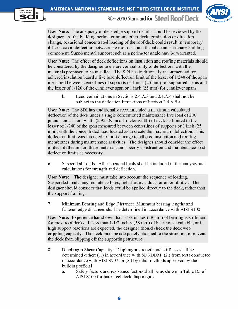
User Note: The adequacy of deck edge support details should be reviewed by the designer. At the building perimeter or any other deck termination or direction change, occasional concentrated loading of the roof deck could result in temporarydifferences in deflection between the roof deck and the adjacent stationary building component. Supplemental support such as a perimeter angle may be warranted.
User Note: The effect of deck deflections on insulation and roofing materials shouldbe considered by the designer to ensure compatibility of deflections with thematerials proposed to be installed. The SDI has traditionally recommended foradhered insulation board a live load deflection limit of the lesser of 1/240 of the span measured between centerlines of supports or 1 inch (25 mm) for supported spans and the lesser of 1/120 of the cantilever span or 1 inch (25 mm) for cantilever spans.
b. Load combinations in Sections 2.4.A.3 and 2.4.A.4 shall not be subject to the deflection limitations of Section 2.4.A.5.a.
User Note: The SDI has traditionally recommended a maximum calculated deflection of the deck under a single concentrated maintenance live load of 200pounds on a 1 foot width (2.92 kN on a 1 meter width) of deck be limited to the lesser of 1/240 of the span measured between centerlines of supports or 1 inch (25mm), with the concentrated load located as to create the maximum deflection. This deflection limit was intended to limit damage to adhered insulation and roofingmembranes during maintenance activities. The designer should consider the effectof deck deflection on these materials and specify construction and maintenance loaddeflection limits as necessary.
6. Suspended Loads: All suspended loads shall be included in the analysis and calculations for strength and deflection.
User Note: The designer must take into account the sequence of loading.Suspended loads may include ceilings, light fixtures, ducts or other utilities. The designer should consider that loads could be applied directly to the deck, rather thanthe support framing.
7. Minimum Bearing and Edge Distance: Minimum bearing lengths and fastener edge distances shall be determined in accordance with AISI S100.
User Note: Experience has shown that 1-1/2 inches (38 mm) of bearing is sufficient for most roof decks. If less than 1-1/2 inches (38 mm) of bearing is available, or ifhigh support reactions are expected, the designer should check the deck webcrippling capacity. The deck must be adequately attached to the structure to preventthe deck from slipping off the supporting structure.
8. Diaphragm Shear Capacity: Diaphragm strength and stiffness shall be determined either: (1.) in accordance with SDI-DDM, (2.) from tests conductedin accordance with AISI S907, or (3.) by other methods approved by the building official.
a. Safety factors and resistance factors shall be as shown in Table D5 of AISI S100 for bare steel deck diaphragms.
6

Steel Roof DeckRD - 2010 Standard for
AmericAn nAtionAl stAndArds institute/ steel deck instituteSTEEL DECKINSTITUTE
s ®
b. Safety factors and resistance factors shall be as follows for deck with fill:
i. When the analytical method of SDI-DDM is used: ASD: Safety Factor (Ω) = 3.25 LRFD: Resistance Factor (Φ) = 0.50 ii. When strength is based on test:
Safety and Resistance Factors shall be determined inaccordance with AISI S100 Chapter F, but for structural concrete fill, shall not be less critical than those for concretediaphragms contained in ACI 318, Section 9.3.
c. When SDI-DDM is the basis of diaphragm design, fasteners andwelds which do not have flexibility and strength properties listed inSDI-DDM Section 4 shall demonstrate flexibility and strengthproperties through testing in accordance with AISI S905 or other equivalent testing methods approved by the building official.Fastener or weld strength defined in AISI S100 or other equivalentmethods approved by the building official shall be permitted.Alternately, it shall be permitted to neglect the contribution of sidelapconnections to diaphragm strength and stiffness. i. Sidelap fillet welds and side seam welds shall be permitted to
have flexibility calculated in accordance with SDI-DDM Section 4.4 and strength calculated in accordance withAISI S100.
9. Fire Resistance: The designer shall consider required fire resistance ratingsin the design of the deck.
User Note: Many fire rated assemblies that use steel roof decks are available. In the Underwriters Laboratories Fire Resistance Directory, the deck constructions show hourly ratings for restrained and unrestrained assemblies. ASTM E119 provides information in appendix X3 titled “Guide for Determining Conditions of Restraintfor Floor and Roof Assemblies and for Individual Beams”.
B. Load Tables: Uniform loads determined for published tables shall be based on equal adjacent two and three span conditions and on single spans. Appropriatecombinations of shear and bending shall be made to determine the published loads. Bearing lengths of 1-1/2 inches (38 mm) for end bearing and 4 inches (100 mm) for interior bearing shall be used to check for web crippling. Strength and deflection shall be calculated using elastic analysis assuming that all spans are equally loaded.Load tables which assume different bearing conditions, span lengths, or loadingcriteria shall be permitted as long as the differing assumptions are clearly noted within the table.User Note: For deck layouts that provide more than three equal spans, the user can apply the loads published for three spans. Equal span uniform load tables do not apply for instances where adjacent spans differ in length by more than 10%.
C. Concentrated Loads: Concentrated loads or combinations of concentrated loads and uniform loads shall be designed using the calculated resistance of the deck and elastic analysis.
7

Steel Roof DeckRD - 2010 Standard for
AmericAn nAtionAl stAndArds institute/ steel deck instituteSTEEL DECKINSTITUTE
s ®
User Note: Concentrated loads are resisted by a distribution width. A “rule of thumb” for 1 ½ inch deck is to use the load footprint width plus 12 inches (300 mm)but not less than an 18 inch (460 mm) distribution width for loads in the middlehalf of the span.
2.5 Connections:A. Deck shall be attached to supports to resist loads and to provide structural stability
for the supporting joist or beam. Connections shall be designed in accordance withAISI S100 or strengths shall be determined by test in accordance with AISI S905.Tests shall be representative of the design. When tests are used and the design allows either end laps or single thickness conditions, both conditions shall be tested.1. Deck shall be anchored to resist the required net uplift forces, but not less
than the following: a. 45 pounds per square foot (2.15 kPa) for eave overhang. b. 30 pounds per square foot (1.44 kPa) for all other roof areas.
2.6 Accessories:A. Accessories for structural applications shall be of dimensions and thickness suitable
for the application, and shall be designed in accordance with AISI S100 or AISC 360, as may be appropriate.
3. Execution
3.1 Installation/General:A. Deck and accessories shall be cut and neatly fit around scheduled openings and other
work projecting through or adjacent to the decking.B. Roof deck shall be anchored to steel supporting members, collectors, drag members,
and perimeter members by arc spot welds, fillet welds, or mechanical fasteners. Type and spacing shall be noted on the drawings. Anchorage shall provide temporarylateral stability to the top flange of the supporting structural members.
User Note: Requirements for necessary bracing strength and stiffness should be determined using the applicable design standard for the member being braced.
C. Edge ribs of panels shall be fastened to each point of support. Additional fasteners between edge ribs shall be spaced an average of 12 inches (300 mm) apart but not more than 18 inches (460 mm).
User Note: The edge rib is the bottom flange of the last rib of a deck panel.
D. For deck with spans greater than 5 feet (1.5 m), side laps shall be fastened at intervals not to exceed 36 inches (1 m) on center, using one of the following methods:
1. Screws with a minimum diameter of 0.190 inches (4.83 mm) (#10 diameter) 2. Crimp or button punch 3. Arc spot welds 5/8 inch (16 mm) minimum visible diameter, minimum 1-
1/2 inch (38 mm) long fillet weld, or other weld shown to be substantially equivalent through testing in accordance with AISI S905, or by calculation in accordance with AISI S100, or other equivalent method approved by thebuilding official.
8

Steel Roof DeckRD - 2010 Standard for
AmericAn nAtionAl stAndArds institute/ steel deck instituteSTEEL DECKINSTITUTE
s ®
4. Side lap fasteners whose strength and flexibilities are determined inaccordance with Section 2.4.A.8.c shall be permitted.
User Note: The above side lap spacing is a minimum. Service loads or diaphragmdesign may require closer spacing or larger side lap welds. Good metal-to-metalcontact is necessary for a good side lap weld. When welding, burn holes are to be expected and are not grounds for rejection. Welds with fusion around 75% of the weld perimeter are considered acceptable. The SDI does not recommend welded sidelaps for deck that is thinner than 0.0358 inch design thickness (20 gage) due to difficulty in welding thinner material.
E. For deck with spans greater than 5 feet (1.5 m), perimeter edges of deck units between span supports shall be fastened at intervals not to exceed 36 inches (1 m) on center, using one of the following methods:
1. Screws with a minimum diameter of 0.190 inches (4.83 mm) (#10 diameter) 2. Arc spot welds with a minimum 5/8 inch (16 mm) minimum visible diameter,
or minimum 1-1/2 inch (38 mm) long fillet weld. 3. Powder actuated or pneumatically driven fasteners.
User Note: Number 10 screws may not be adequate at thicker edge supports and may fracture due to driving torque resistance. A minimum of a Number 12 screw is recommended at parallel edge supports thicker than 14 gage (0.0747 inch) and a Number 14 screw may be required for thicker and harder steels.
F. Support shall be designed and specified by the designer at the perimeter of the roof. G. For cantilevers, side laps shall be attached at the end of the cantilever and at a
maximum spacing of 12 inches (300 mm) on center from the cantilever end at each support. Each corrugation shall be fastened at both the perimeter support and thefirst interior support. The deck shall be completely attached to the supports and at the side laps before any load is applied to the cantilever.
H. Fastener edge distance shall be as required by the applicable fastener designstandard.
I. Deck bearing surfaces shall be permitted to deviate from parallel a maximum of 1:24, but not to exceed 1/16 inch (1.6 mm).
User Note: Out of plane support flanges can create knife-edge supports and air gaps between the deck and support. This makes welding more difficult and allows distortion under screw or power actuated fastener washers or heads.
3.2 WeldingA. All welding of deck shall be in accordance with AWS D1.3. Each welder shall
demonstrate an ability to produce satisfactory welds using a procedure as described in ANSI/AWS D1.3.
User Note: SDI-MOC describes a weld quality control test procedure that can beused as a preliminary check for welding machine settings under ambient conditions.
B. For connection of the deck to the supporting structure, weld washers shall be used with arc spot welds on all deck units with metal thickness less than 0.028 inches (22gage) (0.71 mm). Weld washers shall be a minimum thickness of 0.050 inches (1.27
9

Steel Roof DeckRD - 2010 Standard for
AmericAn nAtionAl stAndArds institute/ steel deck instituteSTEEL DECKINSTITUTE
s ®
mm) and have a nominal 3/8 inch (10 mm) diameter hole. Weld washers shall not beused between supports along the sidelaps.
C. Where weld washers are not required, a minimum visible 5/8 inch (16 mm) diameterarc spot weld or arc seam weld of equal perimeter shall be used. Weld metal shallpenetrate all layers of deck material at end laps and shall have good fusion to the supporting members.
D. When used, fillet welds to support structure shall be at least 1-1/2 inches(38 mm) long.
3.3 Mechanical FastenersA. Mechanical fasteners, either powder actuated, pneumatically driven, or screws, shall
be permitted in lieu of welding to fasten deck to supporting framing, if fasteners meet all project strength and service requirements.
B. When the fasteners are powder actuated or pneumatically driven, the strength per fastener used to determine the maximum fastener spacing is based on a minimumstructural support thickness of not less than 1/8 inch (3mm) and on the fastener providing a minimum 5/16 inch (8mm) diameter bearing surface (fastener head size).Fasteners shall not be installed into structural supports which are outside theacceptable limits of the manufacturers applicable test report or other documentation.
C. When the structural support thickness is less than 1/8 inch (3mm), powder actuatedor pneumatically driven fasteners shall not be used unless lesser support thicknesses are permitted by applicable fastener test report or other documentation acceptable to the designer. Screws shall be acceptable for use without restriction on structural support thickness, however, the screw selected shall have a grip range compatible with the combined thickness of the deck and supporting member.
User Note: Mechanical fasteners (screws, powder or pneumatically driven fasteners, etc.) are recognized as viable anchoring methods, provided the type and spacing of the fastener satisfies the design criteria. Documentation in the form of testdata, design calculations, or design charts should be submitted by the fastenermanufacturer as the basis for obtaining approval. Strength of mechanically fastened connections are dependent upon both deck and support thickness.
3.4 Accessory Attachment:A. Structural accessories shall be attached to supporting structure or deck as required
for transfer of forces, but not to exceed 12 inches (300 mm) on center. Non-structural accessories shall be attached to supporting structure or deck as required forserviceability, but not to exceed 24 inches (600 mm) on center.
B. Mechanical fasteners or welds shall be permitted for accessory attachment.
10


![CSSBI-Steel Roof Deck Floor Deck[1]](https://img.dokumen.tips/doc/110x75/552e8098550346231a8b49af/cssbi-steel-roof-deck-floor-deck1.jpg)