Embed Size (px)
DESCRIPTION
Stealth Warfare for Naval ships
Citation preview
REEDS MARINE ENGINEERING AND TECHNOLOGY
STEALTH WARSHIPTECHNOLOGY
14

Published by Adlard Coles Nautical
an imprint of Bloomsbury Publishing Plc
50 Bedford Square, London WC1B 3DP
www.adlardcoles.com
Copyright © Christopher Lavers 2012
First published by Adlard Coles Nautical in 2012
ISBN 978-1-4081-7525-5
ePDF 978-1-4081-7553-8
ePub 978-1-4081-7552-1
All rights reserved. No part of this publication may be reproduced in any form or by any means –
graphic, electronic or mechanical, including photocopying, recording, taping or information storage and
retrieval systems – without the prior permission in writing of the publishers.
The right of the author to be identifi ed as the author of this work has been asserted by her in accordance with
the Copyright, Designs and Patents Act, 1988.
A CIP catalogue record for this book is available from the British Library.
This book is produced using paper that is made from wood grown in managed, sustainable forests.
It is natural, renewable and recyclable. The logging and manufacturing processes conform to the
environmental regulations of the country of origin.
Typeset in 10.5 pt Baskerville by MPS Ltd
Printed and bound in the UK by MPG Ltd
Note: while all reasonable care has been taken in the publication of this book, the publisher takes no
responsibility for the use of the methods or products described in the book.

The LORD lives!
Praise be to my Rock!
Exalted be God, the Rock, my Saviour!
2 Samuel 22:47 (New International Version – UK)
D3pZ4i & bhgvld, Dennixxx & rosea (for softarchive)Stole src from http://avaxho.me/blogs/exLib/
pgauguin(a.k.a. ExLib) :

This page intentionally left blank

CONTENTSACKNOWLEDGEMENTS IX
INTRODUCTION X
1 RADAR 1Early Radar Stealth 6SR-71 8Measuring Stealth 11Maximum Detection Range (MDR) and Radar Cross Section 13Stealth Approaches 19
2 VISIBILITY 30Dazzle Camoufl age and the First World War 30Origins of Camoufl age 36
3 INVISIBLE FUTURES 52Radar Metamaterials 54Optical Metamaterials 59
4 INFRARED 66Infra-red Heat Reduction 66IRCS Contributors 71The Laws of Infra-red Emission 78
5 MAGNETIC SIGNATURE 82Magnetic Stealth 82Degaussing Ships’ Hulls 86
6 THE ACOUSTIC THREAT AND OTHER SIGNATURES 95Acoustic Noise 95Various Environmental Factors 97Active Sonar 98Passive Sonar 99Sonar Comparison 100Cavitation 102Future Acoustic Technology 103Bioluminescence 104Wake Eff ects 105Extremely Low-Frequency (ELF) Signature 108Likely Future Cross Sections 108Biologically Inspired Design 109Emissions Control Policy 111
viii • Contents
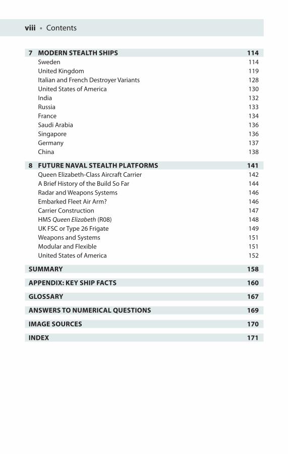
7 MODERN STEALTH SHIPS 114Sweden 114United Kingdom 119Italian and French Destroyer Variants 128United States of America 130India 132Russia 133France 134Saudi Arabia 136Singapore 136Germany 137China 138
8 FUTURE NAVAL STEALTH PLATFORMS 141Queen Elizabeth-Class Aircraft Carrier 142A Brief History of the Build So Far 144Radar and Weapons Systems 146Embarked Fleet Air Arm? 146Carrier Construction 147HMS Queen Elizabeth (R08) 148UK FSC or Type 26 Frigate 149Weapons and Systems 151Modular and Flexible 151United States of America 152
SUMMARY 158
APPENDIX: KEY SHIP FACTS 160
GLOSSARY 167
ANSWERS TO NUMERICAL QUESTIONS 169
IMAGE SOURCES 170
INDEX 171

I would like to thank the following: Mr John Mc Crae for permission to use Type 45 Destroyer HMS Daring images at various construction stages; Mr Andrew Valente, Combat Index Webmaster, LLC, Naples, Florida, USA for archive imagery access; and Mr Kjell Göthe, of Kockums Sweden, for Visby stealth corvette pictures and extensive material about the class. I would also like to thank the meticulous manuscript checking and copy editing provided by the editorial services team at MPS Limited, Chennai.
I appreciate the BBC Radio 4 ‘Material World’ team for letting me loose to talk live about stealth concepts before disappearing ‘on air’ (24th April 2008), which fi rst set me on the path to this book, and the Institute of Physics and the Institute of Materials which both published early crafting of ‘stealth’ ideas in 2008 and 2009.
I would like to thank my family motivators and in turn encourage them: Helena for her work with the disadvantaged of Mexico City, Sam for achieving Ten Tors Gold and teaching in Tanzania, Sara-Kate for her warmth, and care in Guides, Matt for his application of talents and introducing me to football and Ben for his love of learning and stories. I thank them for the few hours of reality each day! Your values and passions add meaning to my life. I thank my parents for motivating me in the past, believing I could learn to read even when my teachers said I wouldn’t! Finally, I especially thank Anne, my wife, for her patience and encouragement; you are the true love of my life.
To all and one I thank you.
ACKNOWLEDGEMENTS
The missile navigating by inertial guidance approached with swift self-assurance
the end of its 200 nautical mile pre-programmed journey, and after rapid target
confi rmation with its passive thermal imager reaches its objective to devastating
eff ect. The target, oblivious of its peril, until the fi nal moment of impact, could do
nothing to counter this fatal blow.
Christopher Lavers
The scenario outlined above is not fi ction; it is the real high-technology cutting edge of naval warfare today. For this reason, surface warships incorporated with stealth technologies take an increasingly vital role to ensure platform survival. Stealth’s principal aim is to make naval ships ‘invisible’ to an array of increasingly smart detection systems such as sonar and radar, combining ways that lower a platform’s emissions and those which eliminate refl ected radiation, thus reducing detection range and threat vulnerability. This book seeks to communicate the latest interesting developments in stealth technology to a wider audience and to explore the paradigm shift ‘stealth’ represents in terms of warship design. It will focus on the transformational change in naval architecture, which is simplistically represented in the shape of modern warships, and dwells less on just providing lots of information or technical detail. Stealth Warship Technology will also discuss in a little detail something of the history of this subject. In this book, I will provide an opportunity to develop a better understanding of the specialist practical issues and skills required in this naval sector. Some opportunity for basic numerical analysis and problem-solving are included at the end of each chapter for the more mathematical reader. However, the book is designed for those with a limited mathematical background in mind; it is my objective to communicate the fundamental principles of the subject to the many and not to provide tricky maths problems to solve for the few.
I will discuss several ongoing themes or issues throughout the book: surveillance, signature and cross section reduction as well as certain aspects of electronic warfare (EW). Surveillance entails an examination of both radar and infra-red non-imaging target detection systems as well as the latest visual and thermal imaging systems. The developments in high-resolution radar imaging cannot be underestimated in their signifi cance at the beginning of the twenty-fi rst century to future platform survivability.
INTRODUCTION
Introduction • xi
Signature and cross section reduction consideration will investigate the various applied techniques that have been utilised to date and those which are likely to be employed to make ship targets less visible to current (and future) generations of surveillance systems. The topic of EW elicits a double-edged response from the informed reader. EW involves the role of largely passive electronic support measures (ESM), the ‘listening’ devices which need to be coordinated with further electronic countermeasures (ECM) (various active and passive techniques available), and is both our best friend and, being also used by an equally surveillant enemy, perhaps our greatest foe.
The aim of this book is to ‘uncover’ the unto now ‘secret’ area of stealth warship design and the broader aspects of stealth technology using available public material and to stress the importance of materials used in the warship’s construction with information that already exists in the public domain, and how this infl uences all of a modern naval platform’s design parameters. Paradoxically, all the basic stealth concepts are easily accessible on the Internet, with a variety of stealth-related companies discussing their products in some detail. To a physicist or engineer who knows what they are looking for, even YouTube videos can now provide signifi cant intelligence on both systems and their capabilities and mode of operation, saying nothing of the ability of modern mobile phones to provide a wealth of additional information and infl uence, as seen in the Arab Spring of 2011. A working title for this book was initially ‘Electromagnetic threats to warships’, but this not only fails to grasp the full extent of warship threats which encompass the traditional role of radar and visual detection, as well as night-vision devices and thermal imaging capability, but also does not address the acoustic underwater signature of the ship platform and other less well-known detection methods such as magnetic signature, bioluminescence, and wake and so on. It must be stressed from the outset that there has been a signifi cant paradigm shift in warship design in the past two decades, which has been rather to move away from the view that it is simply nice to incorporate stealth into warship design as something of an aff ordable extra if possible. Instead stealth is now seen to be the critical component around which the warship is designed, and is certainly the case for the DD(X) Zumwalt-class surface combatant. However, it is the very cost of stealth that has made the Zumwalt a victim of its own stealth success, and mitigated against the future of the programme, in favour of a more traditionally tried and tested warships. The shift in emphasis towards stealth in current platforms is evidenced through the radical transformation of platform design between the RN Type 23 frigate and the latest stealth Type 45 Destroyer HMS Daring as well as the La Fayette-class frigate and Swedish Visby stealth class corvette built by Kockums.
An able reader or student should be able to describe, discuss and analyse the ways in which modern and often highly complex sensors and communications systems can
xii • Introduction
have their performance degraded by hostile activities. We will consider the various design techniques which might be incorporated to negate the eff ects of these activities and to reduce likewise the overall probability of a ship’s detection.
Clearly stealth is only a part of the story, as a stealth warship cannot provide the same sense of intimidating power projection off the coast of a potential enemy if they do not know that you are there, and neither can stealth ensure platform safety and integrity once the fi rst salvo is fi red. Obviously there is still a signifi cant role to be maintained in terms of self-protection of a platform, and the increased cost that stealth brings to the value of the ship asset is only likely to increase the required investment in ship’s defences, be they long- and short-range missile defence systems, a close-in weapon system (CIWS) or gun as well as various soft-kill methods at the ship’s disposal. Stealth can actually provide a range advantage over a variety of sensor systems, and the reduced signature provides a suffi ciently ‘fuzzy picture’ that an enemy may at best detect you but will be quite unable to classify the threat correctly.
According to Merriam-Webster’s Online Dictionary, ‘stealth’ (pronounced: stelth) is derived from the thirteenth-century ‘Middle English stelthe; akin to Old English stelan to steal’, with several related meanings.
1 a archaic: theft b obsolete: something stolen
2 the act or action of proceeding furtively, secretly, or imperceptibly ‘the state moves by stealth to gather information – Nat Hentoff ’
3 the state of being furtive or unobtrusive [and in the context we will be considering]
4 an aircraft-design characteristic consisting of oblique angular construction and avoidance of vertical surfaces that is intended to produce a very weak radar return
Stealth technology is also known as low observable technology (LOT) and is a sub-discipline of ECM, which covers a range of techniques used not just with aircraft, but includes ships and missiles, in order to make them less visible (ideally invisible) to radar, infra-red and other detection methods.
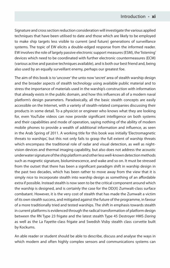
There are also issues presented by the class of threat that the stealth warship has been constructed to deal with, as the most likely asymmetric threats that will present themselves to warships in the near future are the small (and ironically stealthy) fast boats manned by pirates, insurgents or terrorists, like those who caused damage to the USS Cole, an Arleigh Burke-class destroyer. The USS Cole was the target of a terrorist
Introduction • xiii
attack in the port of Aden in October 2000, during a scheduled re-fuelling. The attack killed 17 crew members and injured 39 others, demonstrating that even a heavily armed high-tech platform is still vulnerable to relatively simple threats (Figure I1).
As the ancient Chinese general Sun Tzu wrote in his The Art of War, dating back to 450 BC and the world’s oldest treatise on military strategy, ‘All warfare is based on deception’, and certainly warships stealth and signature reduction techniques play an increasing component in that deception today. Stealth can generally be regarded as any technique used to reduce refl ected sources of radiation, mostly with passive measures, whilst signature reduction involves methods designed specifi cally to reduce a ship’s own emissions – methods which are largely active. In reality, though, the terms ‘stealth’ and ‘signature reduction’ are used fairly interchangeably. The oldest and most successful recorded reference to deception before the modern era is that illustrated in the book of Judges (6–7) concerning Gideon who with 300 men, trumpets, torches hidden in jars and precision timing at the change of the enemy guard routed a much larger force.
15When Gideon heard the dream and its interpretation, he worshiped God. He returned to the camp of Israel and called out, ‘Get up! The LORD has given the Midianite camp into your hands.’ 16Dividing the 300 men into 3 companies,
Figure I1 The USS Cole (DDG 67) is towed away from the port city of Aden, Yemen, into open sea by the Military Sealift Command ocean-going tug USNS Catawba (T-ATF 168) on 29 October 2000
xiv • Introduction
he placed trumpets and empty jars in the hands of all of them, with torches inside … 19Gideon and the 100 men with him reached the edge of the camp at the beginning of the middle watch, just after they had changed the guard. They blew their trumpets and broke the jars that were in their hands. 20The 3 companies blew the trumpets and smashed the jars. Grasping the torches in their left hands and holding in their right hands the trumpets they were to blow, they shouted, ‘A sword for the LORD and for Gideon!’ 21While each man held his position around the camp, all the Midianites ran, crying out as they fl ed.
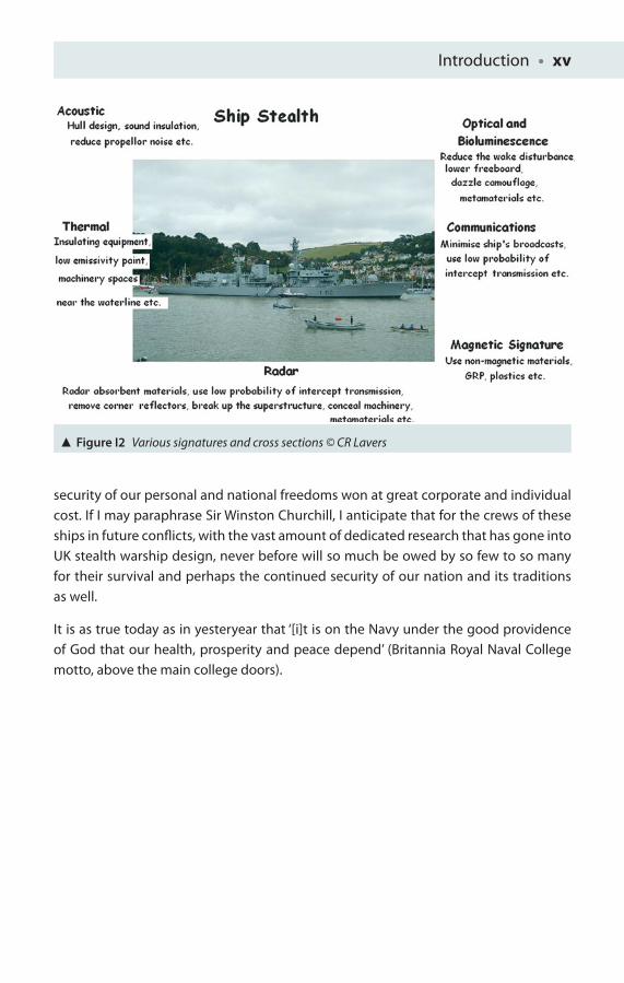
You could even regard this as the fi rst example of coordinated, network-centric warfare! Certainly the desire for ‘invisibility’ until the fi nal moment of attack has been a key infl uence in how warfare has been conducted since ancient times. The military quest for invisibility appears in Greek mythology: Perseus’ helmet and Gyge’s ring both rendered their wearers invisible, useful when fi ghting monsters, and also formed the basis for the ‘One Ring’ in Tolkien’s famous trilogy The Lord of the Rings. However, such abilities no longer belong entirely in the realm of fantasy or science fi ction such as Star Trek, as these days the world’s armed forces can draw on sophisticated stealth techniques to hide themselves from their enemies. Stealth technology seeks to render military ships, vehicles, men and aircraft ‘invisible’ to modern detection systems, such as radar and magnetic sensors, by reducing the levels of refl ected radiation whilst at the same time lowering the craft’s own emissions (Figure I2). I will examine the various applied techniques that have been, and are likely to be, employed to make a platform less prone to detection. Certainly if these techniques are applied successfully, eff ective targeting, although perhaps not impossible, will be highly unlikely, whilst at the same time countermeasure systems will attempt to deny the enemy the tactical use of the electromagnetic spectrum (and acoustic spectrum) whilst retaining one’s own use of military spectral capabilities.
When it comes to an aircraft carrier or large battleship, this is no mean feat. Stealth works hand in hand with precision, and it is no accident that stealth aircraft today use precision-guided munitions to great effect. Stealth also works in partnership with modern decoy systems, as the harder it is to ‘see’ the real target, the more likely that a decoy system will be selected as the chosen target because of the larger more attractive signal it may provide. We will start our discussion of stealth with radar, a sensor many readers will be familiar with, followed by the visible spectrum, infra-red spectrum, various other spectra and finally an examination of modern stealth ships themselves.
For me, the real issues of stealth are not driven by academic interest alone but in terms of considering the safety provided to a vulnerable crew at sea and the preservation and
Introduction • xv
security of our personal and national freedoms won at great corporate and individual cost. If I may paraphrase Sir Winston Churchill, I anticipate that for the crews of these ships in future confl icts, with the vast amount of dedicated research that has gone into UK stealth warship design, never before will so much be owed by so few to so many for their survival and perhaps the continued security of our nation and its traditions as well.
It is as true today as in yesteryear that ‘[i]t is on the Navy under the good providence of God that our health, prosperity and peace depend’ (Britannia Royal Naval College motto, above the main college doors).
Figure I2 Various signatures and cross sections © CR Lavers

This page intentionally left blank

RADAR1
[A]head towards London I saw a small, tight formation of bombers completely
encircled by a ring of Messerschmitts. They were still heading north. As I raced
forward, three fl ights of Spitfi res came zooming up from beneath them in a sort of
Prince-of-Wales’s-feathers manoeuvre. They burst through upward and outward,
their guns going all the time. They must have each got one, for an instant later I
saw the most extraordinary sight of eight German bombers and fi ghters diving
earthward together in fl ames.
John Beard, ‘Battle of Britain, 1940’ [1]
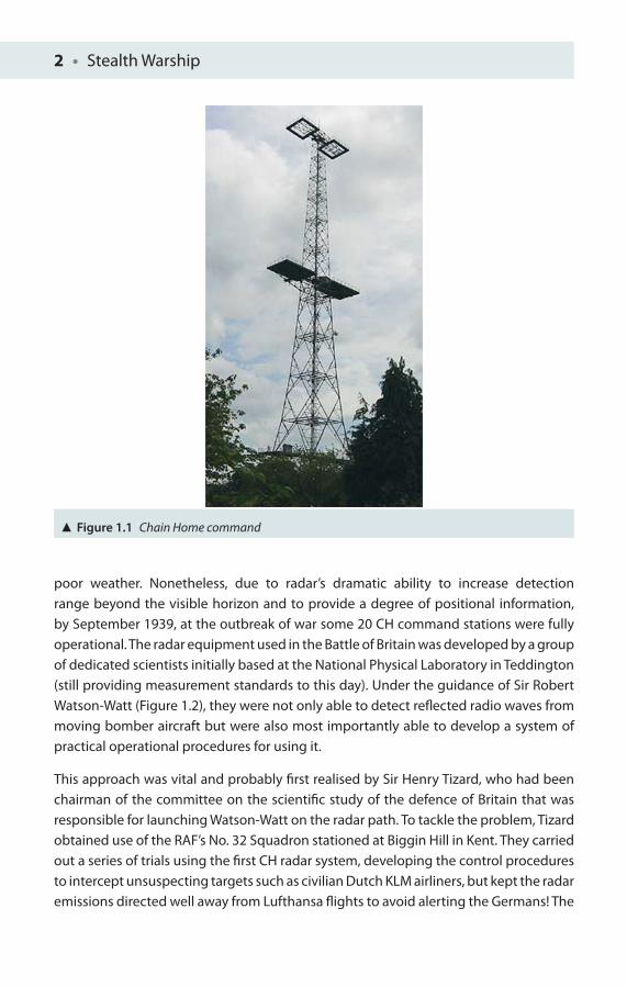
The story of modern radar and with it the radar technology to counter its eff ectiveness, ‘stealth’, is where we will begin, arising as it did out of the rearmament of Nazi Germany in the 1930s and the signifi cant expansion of the German Luftwaff e. The British government was alarmed at the rapidity of these developments and soon realised that an aircraft warning system had to be developed and quickly deployed in the likelihood of imminent war. In January 1935, Sir Robert Watson-Watt was asked whether radio waves might be used to detect aircraft approaching the shores of England. Sir Watson-Watt wrote a brief memorandum to the Air Defence Subcommittee of the Committee of Imperial Defence to promote developments of radio direction fi nding (DF). Based on this letter and the supportive eff orts of Sir Henry Tizard, a concentrated radar development programme began in England. In 1937, a prototype radio DF station (later called the Chain Home (CH) system; Figure 1.1) was built at Bawdsey Research Station for Royal Air Force (RAF) use. The CH station operated at a relatively low frequency of 22 MHz, and was able to detect propeller-driven aircraft at a modest 3,000 m elevation and under good atmospheric conditions as far away as 150 km in fi ne weather but, due to absorption of radar energy by weather fronts and rain, substantially less in
2 • Stealth Warship
poor weather. Nonetheless, due to radar’s dramatic ability to increase detection range beyond the visible horizon and to provide a degree of positional information, by September 1939, at the outbreak of war some 20 CH command stations were fully operational. The radar equipment used in the Battle of Britain was developed by a group of dedicated scientists initially based at the National Physical Laboratory in Teddington (still providing measurement standards to this day). Under the guidance of Sir Robert Watson-Watt (Figure 1.2), they were not only able to detect refl ected radio waves from moving bomber aircraft but were also most importantly able to develop a system of practical operational procedures for using it.
This approach was vital and probably fi rst realised by Sir Henry Tizard, who had been chairman of the committee on the scientifi c study of the defence of Britain that was responsible for launching Watson-Watt on the radar path. To tackle the problem, Tizard obtained use of the RAF’s No. 32 Squadron stationed at Biggin Hill in Kent. They carried out a series of trials using the fi rst CH radar system, developing the control procedures to intercept unsuspecting targets such as civilian Dutch KLM airliners, but kept the radar emissions directed well away from Lufthansa fl ights to avoid alerting the Germans! The
Figure 1.1 Chain Home command

Radar • 3
Figure 1.2 Sir Robert Watson-Watt
Figure 1.3 German Heinkel He 111s which went into service in 1937
4 • Stealth Warship
procedures developed during this experiment were those later used by British aircraft controllers during the strategically important Battle of Britain fought fi ercely from the summer of 1940 well into the autumn (10 July–31 October 1940) (Figure 1.3).
This was indisputably the fi rst modern example of a network-centric warfare, where the assets of a signifi cantly depleted RAF were able to be accurately vectored to intercept German bomber aircraft. This uncanny ability of the British RAF to intercept German Luftwaff e sorties led the German’s high command to gain the false impression that Britain had a much larger air force and was partly responsible for the abandonment of the planned Nazi invasion of Britain (Operation Sea Lion). It was this combination of the hardware and operational ‘software’ in use that made radar so vital and successful to the British. The German failure to achieve its objective of the complete annihilation of Britain’s air defences, or indeed an outright surrender, is rightly considered a critical turning point in the Second World War and stiff ened British determination and defi ance.
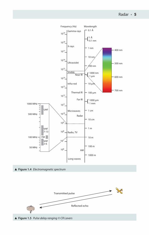
The basic principle of radar, or more strictly echo location, is quite simple. Visible light, of which we are all familiar, is but part of a wider family of waves which form the electromagnetic spectrum (Figure 1.4), covering waves such as X-rays, gamma rays and ultraviolet radiation which all have more energy than visible light and also waves of longer wavelength, such as infra-red (heat), radar and very low-frequency (VLF) waves used to communicate with submerged submarines.
If these electromagnetic waves are sent in the form of short pulses which strike an object with a fl at surface, some of the wave energy transmitted from the radar will be refl ected back to the radar receiver, similar to the optical dazzle observed from solar ‘glint’ off a sunlit window on a sunny day (Figure 1.5).
If the elapsed time t, from the transmission of a short radar pulse to the time the echo is received, is measured, the wave speed allows the contact range to be calculated accurately. As electromagnetic waves all travel at the same speed of light in vacuum, and only a little less in our planet’s dilute atmosphere (c = 3 × 10⁸ m s−1), the distance they travel may be given as follows: distance = ct. Hence contact range R, which is half the total distance, is given as follows: R = ct __ 2 .
For example, if the elapsed recorded electronic time from pulse transmission to reception is one thousandth of a second (or 1 ms), the radar range from the transmitter to the refl ecting target will be as follows:
(3 × 108 × 1 × 10−3) _________________
2 m or 150 km distance
This relationship is used frequently in pulse radars to measure contact range, and the method is often referred to as ‘pulse delay ranging’. Other important radar parameters include the transmitted radar frequency (denoting the energy of the wave), the pulse repetition frequency or PRF (the number of pulses transmitted per second) and the pulse duration.
Radar • 5
Figure 1.4 Electromagnetic spectrum
Long-waves
AM
1000 m
100 m
10 m
1 m
10 cm
100 μm
100 nm
10 nm
400 nm
500 nm
600 nm
700 nm
1 nm
10 μm
1 cm
1 mm1000 MHz
500 MHz
UHF
VHF
VHF
7-13
2-6
FM100 MHz
50 MHz
1000 μm
1 μm1000 nm
0.1 nm1 Å
Gamma-rays
Frequency (Hz) Wavelength
1019
1018
1017
1016
1015
1014
1013
1012
1011
1010
109
108
107
106
X-rays
Ultraviolet
VisibleNear IR
Thermal IR
Far IR
Radar
Infra-red
Microwaves
Radio, TV
0.1 Å
Transmitted pulse
Reflected echo
Figure 1.5 Pulse delay ranging © CR Lavers
6 • Stealth Warship
Early Radar Stealth
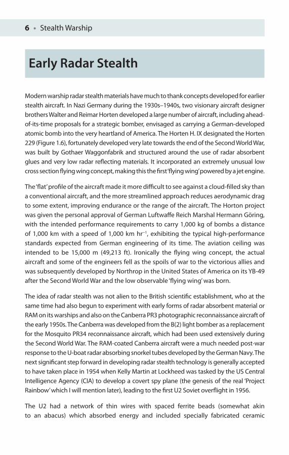
Modern warship radar stealth materials have much to thank concepts developed for earlier stealth aircraft. In Nazi Germany during the 1930s–1940s, two visionary aircraft designer brothers Walter and Reimar Horten developed a large number of aircraft, including ahead-of-its-time proposals for a strategic bomber, envisaged as carrying a German-developed atomic bomb into the very heartland of America. The Horten H. IX designated the Horten 229 (Figure 1.6), fortunately developed very late towards the end of the Second World War, was built by Gothaer Waggonfabrik and structured around the use of radar absorbent glues and very low radar refl ecting materials. It incorporated an extremely unusual low cross section fl ying wing concept, making this the fi rst ‘fl ying wing’ powered by a jet engine.
The ‘fl at’ profi le of the aircraft made it more diffi cult to see against a cloud-fi lled sky than a conventional aircraft, and the more streamlined approach reduces aerodynamic drag to some extent, improving endurance or the range of the aircraft. The Horton project was given the personal approval of German Luftwaff e Reich Marshal Hermann Göring, with the intended performance requirements to carry 1,000 kg of bombs a distance of 1,000 km with a speed of 1,000 km hr−1, exhibiting the typical high-performance standards expected from German engineering of its time. The aviation ceiling was intended to be 15,000 m (49,213 ft). Ironically the fl ying wing concept, the actual aircraft and some of the engineers fell as the spoils of war to the victorious allies and was subsequently developed by Northrop in the United States of America on its YB-49 after the Second World War and the low observable ‘fl ying wing’ was born.
The idea of radar stealth was not alien to the British scientifi c establishment, who at the same time had also begun to experiment with early forms of radar absorbent material or RAM on its warships and also on the Canberra PR3 photographic reconnaissance aircraft of the early 1950s. The Canberra was developed from the B(2) light bomber as a replacement for the Mosquito PR34 reconnaissance aircraft, which had been used extensively during the Second World War. The RAM-coated Canberra aircraft were a much needed post-war response to the U-boat radar absorbing snorkel tubes developed by the German Navy. The next signifi cant step forward in developing radar stealth technology is generally accepted to have taken place in 1954 when Kelly Martin at Lockheed was tasked by the US Central Intelligence Agency (CIA) to develop a covert spy plane (the genesis of the real ‘Project Rainbow’ which I will mention later), leading to the fi rst U2 Soviet overfl ight in 1956.
The U2 had a network of thin wires with spaced ferrite beads (somewhat akin to an abacus) which absorbed energy and included specially fabricated ceramic
Radar • 7
Figure 1.6 Horten H. IX designs
Figure 1.7 Shuttle heat tiles © CR Lavers
8 • Stealth Warship
Figure 1.8 SR-71
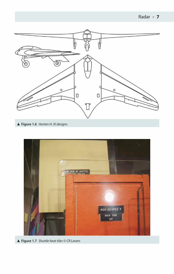
wing leading edges, made of fi breglass and honeycomb plastic, skimmed or fi nished with heat-resistant fi breglass. Such developments in ceramic heat-resistant tiles have continued over the decades and led eventually to the technology being deployed on the series of US space shuttles (Figure 1.7), and which when damaged led to the devastation observed on the shuttle Columbia (1st February 2003). The U2 aircraft was a fi rst step along the path of focused stealth aviation.
SR-71
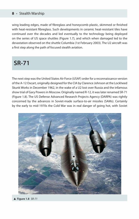
The next step was the United States Air Force (USAF) order for a reconnaissance version of the A-12 Oxcart, originally designed for the CIA by Clarence Johnson at the Lockheed Skunk Works in December 1962, in the wake of a U2 lost over Russia and the infamous show trial of Gary Powers in Moscow. Originally named R-12, it was later renamed SR-71 (Figure 1.8). The US Defense Advanced Research Projects Agency (DARPA) was rightly concerned by the advances in Soviet-made surface-to-air missiles (SAMs). Certainly by the early to mid-1970s the Cold War was in real danger of going hot, with Soviet
Radar • 9
nuclear testing and arms proliferation apace. There was a genuine climate of fear of the perceived Soviet missile build-up. The SR-71 was longer and heavier than the A-12. Its fuselage was lengthened for additional fuel capacity and for increased range. A second seat was added to the cockpit and further reconnaissance equipment included intelligence sensors, a side-looking radar and a photo camera. The SR-71 ‘Blackbird’ fi rst fl ew on 22nd December 1984 and was fi nally ‘retired’ from USAF service in 1998. The mission intent of the SR-71 was to provide the same sort of reconnaissance capability provided by the U2 programme, but it had the unique advantage with its Mach 3+ speed that if an enemy surface-to-air missile was launched and subsequently detected the aircraft could simply accelerate to outrun the missile! Thirty-two SR-71s were built, with none of them lost to enemy action, although 12 aircraft (a rather high number) were destroyed in a variety of accidents. Since 1976, the SR-71 has maintained its offi cial record as the fastest air-breathing manned aircraft in the world.
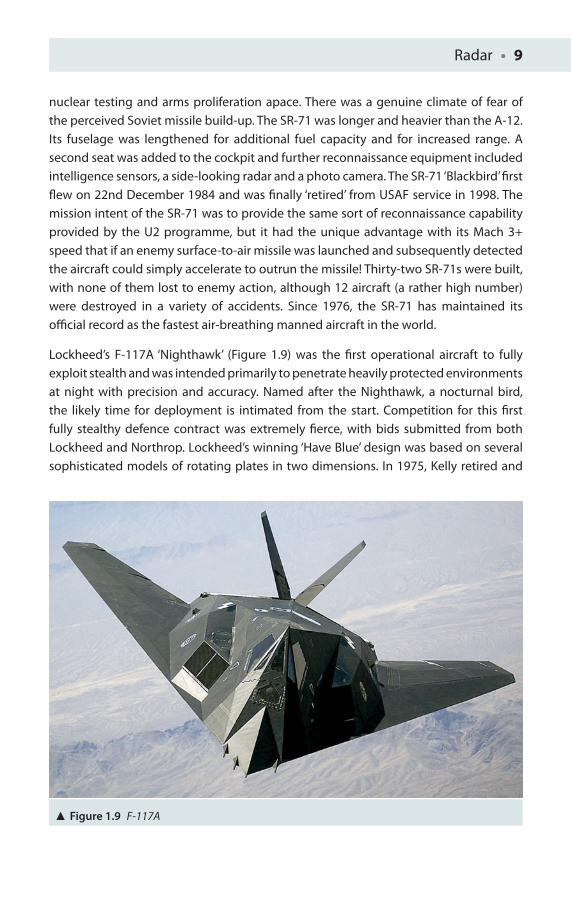
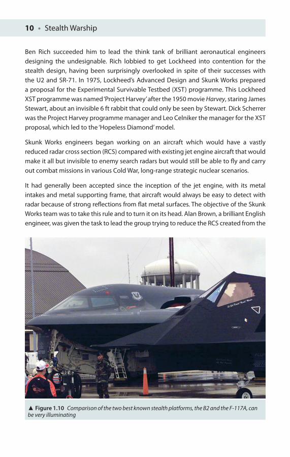
Lockheed’s F-117A ‘Nighthawk’ (Figure 1.9) was the fi rst operational aircraft to fully exploit stealth and was intended primarily to penetrate heavily protected environments at night with precision and accuracy. Named after the Nighthawk, a nocturnal bird, the likely time for deployment is intimated from the start. Competition for this fi rst fully stealthy defence contract was extremely fi erce, with bids submitted from both Lockheed and Northrop. Lockheed’s winning ‘Have Blue’ design was based on several sophisticated models of rotating plates in two dimensions. In 1975, Kelly retired and
Figure 1.9 F-117A
10 • Stealth Warship
Ben Rich succeeded him to lead the think tank of brilliant aeronautical engineers designing the undesignable. Rich lobbied to get Lockheed into contention for the stealth design, having been surprisingly overlooked in spite of their successes with the U2 and SR-71. In 1975, Lockheed’s Advanced Design and Skunk Works prepared a proposal for the Experimental Survivable Testbed (XST) programme. This Lockheed XST programme was named ‘Project Harvey’ after the 1950 movie Harvey, staring James Stewart, about an invisible 6 ft rabbit that could only be seen by Stewart. Dick Scherrer was the Project Harvey programme manager and Leo Celniker the manager for the XST proposal, which led to the ‘Hopeless Diamond’ model.
Skunk Works engineers began working on an aircraft which would have a vastly reduced radar cross section (RCS) compared with existing jet engine aircraft that would make it all but invisible to enemy search radars but would still be able to fl y and carry out combat missions in various Cold War, long-range strategic nuclear scenarios.
It had generally been accepted since the inception of the jet engine, with its metal intakes and metal supporting frame, that aircraft would always be easy to detect with radar because of strong refl ections from fl at metal surfaces. The objective of the Skunk Works team was to take this rule and to turn it on its head. Alan Brown, a brilliant English engineer, was given the task to lead the group trying to reduce the RCS created from the
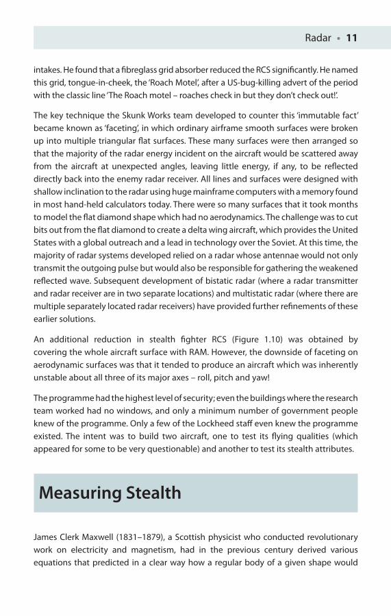
Figure 1.10 Comparison of the two best known stealth platforms, the B2 and the F-117A, can be very illuminating
Radar • 11
intakes. He found that a fi breglass grid absorber reduced the RCS signifi cantly. He named this grid, tongue-in-cheek, the ‘Roach Motel’, after a US-bug-killing advert of the period with the classic line ‘The Roach motel – roaches check in but they don’t check out!’.
The key technique the Skunk Works team developed to counter this ‘immutable fact’ became known as ‘faceting’, in which ordinary airframe smooth surfaces were broken up into multiple triangular fl at surfaces. These many surfaces were then arranged so that the majority of the radar energy incident on the aircraft would be scattered away from the aircraft at unexpected angles, leaving little energy, if any, to be refl ected directly back into the enemy radar receiver. All lines and surfaces were designed with shallow inclination to the radar using huge mainframe computers with a memory found in most hand-held calculators today. There were so many surfaces that it took months to model the fl at diamond shape which had no aerodynamics. The challenge was to cut bits out from the fl at diamond to create a delta wing aircraft, which provides the United States with a global outreach and a lead in technology over the Soviet. At this time, the majority of radar systems developed relied on a radar whose antennae would not only transmit the outgoing pulse but would also be responsible for gathering the weakened refl ected wave. Subsequent development of bistatic radar (where a radar transmitter and radar receiver are in two separate locations) and multistatic radar (where there are multiple separately located radar receivers) have provided further refi nements of these earlier solutions.
An additional reduction in stealth fi ghter RCS (Figure 1.10) was obtained by covering the whole aircraft surface with RAM. However, the downside of faceting on aerodynamic surfaces was that it tended to produce an aircraft which was inherently unstable about all three of its major axes – roll, pitch and yaw!
The programme had the highest level of security; even the buildings where the research team worked had no windows, and only a minimum number of government people knew of the programme. Only a few of the Lockheed staff even knew the programme existed. The intent was to build two aircraft, one to test its fl ying qualities (which appeared for some to be very questionable) and another to test its stealth attributes.
Measuring Stealth
James Clerk Maxwell (1831–1879), a Scottish physicist who conducted revolutionary work on electricity and magnetism, had in the previous century derived various equations that predicted in a clear way how a regular body of a given shape would
12 • Stealth Warship
refl ect or scatter electromagnetic waves. With the help of a 1966 paper Method of Edge Waves in the Physical Theory of Diff raction published by a Russian physicist Pyotr Ufi mtsev at the Moscow Institute of Theoretical Physics (and now at the time of writing, running a small one-man company Electromagnetics Research in Los Angeles), a paper which was largely ignored in the then Soviet Union, two Skunk Works engineers Bill Schroeder and Denys Overholser fi gured out the key maths behind stealth control surface design. Schroeder sketched an aircraft with no curved surfaces at all, except those of relatively small radius, with straight edges to its wings and tail surfaces. It was as if a diamond had been cut into the crude outline shape of an aircraft, albeit a fairly unaerodynamic looking one. Schroeder took the problem to Denys Overholser, an able software engineer who could think outside of the frame of what already existed. Using the number-crunching capability of an at that time state-of-the-art Cray computer, Overholser developed a computer program that modelled scattering from Schroeder’s new and peculiar faceted shapes, and predicted their theoretical RCS. However, it would not be satisfactory to stop with just the output of unvalidated computer models, but in true engineering fashion it required testing to prove the validity of these models. From the computer program, engineers created a 10 ft wooden model dubbed the ‘Hopeless Diamond’, which was taken to a secret outdoor radar test range in the Mojave Desert near Palmdale. The model was mounted on a 12 ft pole, and the radar dish placed 1,500 ft away. Apparently, if the anecdotal test reports are to be believed, the site radar operator could not see the model on the radar until a black bird landed right on top of the model. The radar detected the bird but not the aircraft scale model!
Some introduction needs to be made to the often quoted size of a target on a radar system. Unlike the familiar size of an object that we can see in the visible part of the electromagnetic spectrum and physically measure with a metre ruler, things are not quite so obvious in other parts of the electromagnetic spectrum. The size of a target’s image on radar is measured by its RCS, often represented by the symbol σ and is expressed in square metres. However, this ‘area’ does not equal its geometric area. A perfectly conducting sphere of projected cross-sectional area 1 m2, that is, diameter of 1.13 m, when measured on a test rig will be found to have an RCS of 1 m2 (or as close as likely to occur within experimental error!). A test aircraft returning twice as much energy as the test sphere would be said to have an RCS of 2 m2. Similarly a square fl at plate of area 1 m2 will have an RCS of σ = 4πA2/λ2 = 13,982 m2, where A is area and λ is the wavelength at 10 GHz if the radar is set to transmit pulses perpendicular to the fl at face [2]. At off normal incident angles, energy is refl ected away from the receiver, thereby reducing the RCS. So a small plate can generate a massive echo signal or RCS on the ‘enemy’ radar display.
Consequently, by appropriate choices of material, shape and size, a typical fi ghter aircraft having an actual area of 10 m2 when directly facing the radar system could
Radar • 13
return much less energy than the echo energy returned by a test sphere returning an RCS of even a few square centimetres, thus bearing no relationship to the actual area of the plane in real life. The inherently unaerodynamic ‘brick’ shape of the Hopeless Diamond was superseded by the ‘continuous curvature’ approach of the B2, a larger aircraft yet with a smaller cross section and with a shape lending itself to a more aerodynamic platform.
Maximum Detection Range (MDR) and Radar Cross Section
An individual search radar set’s MDR depends upon several factors such as transmitted power, the target’s refl ecting properties, the antenna or aerial size and the receiver’s sensitivity. The MDR is given by simplifying the standard radar range equation, to fi nd the maximum range a radar will detect a chosen target of a given size [3].
MDR = 4 √_______
PGσt
otA
eff _______ (4σ)2S
min
Here, P is the average transmitted power, G is the antenna gain, σ is the RCS of the chosen target (a measure of the contact size seen by the radar beam), t
ot is the time
the contact is illuminated by the radar beam, Aeff
is the eff ective size of the receive antenna and S
min is the minimum signal energy required for detection by the receiver.
Any change in these parameters will change the MDR. Generally speaking, wave loss increases with increasing frequency and so MDR will fall. Clearly, the ship’s search radar has control of all but the elusive RCS of the chosen target. However, from the radar operator’s perspective trying to counter stealth, a suitable combination of these fi ve factors can counterbalance a moderate reduction in the airplane’s overall RCS. It is quite possible for a fi re-control radar, with a highly directional beam (or high gain antenna) and a moderately high power level to track stealth aircraft and even potentially engage them successfully as evidenced by the F-117A taken down over Bosnia (believed to be due to a modifi ed surface-to-air battery SA3 or SA6 and initial intelligence of the planned fl ight path, which was thought to be similar to a previous fl ight). It was also believed subsequently that with the Soviet help and clever algorithms the Serbs had used the radar to detect the ‘lack of aircraft refl ectivity’ against its background. The aircraft was destroyed on 27 March 1999 during the NATO bombing of Serbia after the aircraft was shot down in combat 25 miles west of Belgrade, with pieces shown on Serbian TV. There have been at least six notable incidents of stealth aircraft losses, including a very public black jet loss at the Baltimore air show in September 1997 with
14 • Stealth Warship
an aircraft disintegrating in mid-air and crashing to earth in an urban area. Miraculously no one was killed. However, the most potent threat since the Vietnam War to any aircraft lies in the realm of infra-red heat-seeking systems which we will briefl y consider later. Interestingly, it was believed that Serbian forces had received considerable help from Russian intelligence offi cers regarding the downing of the F-117A and were quick to swarm over the remains of the aircraft looking for surviving salvageable parts, including bits of fi rst-generation US stealth materials. Russian interest lay in the subsequent analysis of the frequency-dependent response of such stealth materials in order to fi nd frequencies or, one might say, weaknesses, in response for which the F-117A would be more vulnerable to detection.
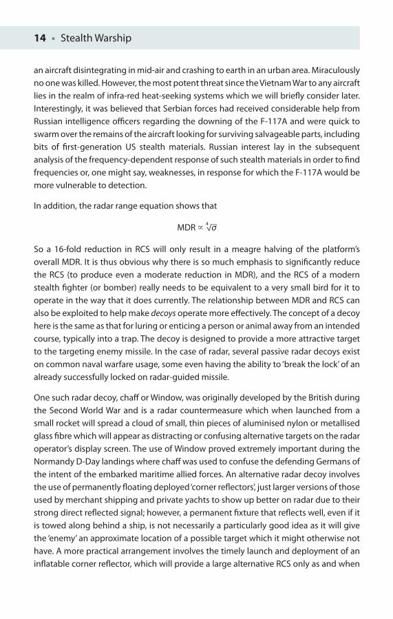
In addition, the radar range equation shows that
MDR � 4 √__
σ
So a 16-fold reduction in RCS will only result in a meagre halving of the platform’s overall MDR. It is thus obvious why there is so much emphasis to signifi cantly reduce the RCS (to produce even a moderate reduction in MDR), and the RCS of a modern stealth fi ghter (or bomber) really needs to be equivalent to a very small bird for it to operate in the way that it does currently. The relationship between MDR and RCS can also be exploited to help make decoys operate more eff ectively. The concept of a decoy here is the same as that for luring or enticing a person or animal away from an intended course, typically into a trap. The decoy is designed to provide a more attractive target to the targeting enemy missile. In the case of radar, several passive radar decoys exist on common naval warfare usage, some even having the ability to ‘break the lock’ of an already successfully locked on radar-guided missile.
One such radar decoy, chaff or Window, was originally developed by the British during the Second World War and is a radar countermeasure which when launched from a small rocket will spread a cloud of small, thin pieces of aluminised nylon or metallised glass fi bre which will appear as distracting or confusing alternative targets on the radar operator’s display screen. The use of Window proved extremely important during the Normandy D-Day landings where chaff was used to confuse the defending Germans of the intent of the embarked maritime allied forces. An alternative radar decoy involves the use of permanently fl oating deployed ‘corner refl ectors’, just larger versions of those used by merchant shipping and private yachts to show up better on radar due to their strong direct refl ected signal; however, a permanent fi xture that refl ects well, even if it is towed along behind a ship, is not necessarily a particularly good idea as it will give the ‘enemy’ an approximate location of a possible target which it might otherwise not have. A more practical arrangement involves the timely launch and deployment of an infl atable corner refl ector, which will provide a large alternative RCS only as and when
Radar • 15
required in the close vicinity of the ship. Many navies of the world now possess the ability to launch chaff rounds routinely.
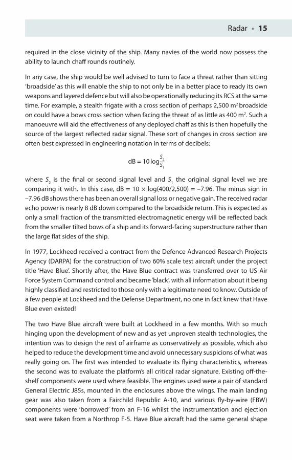
In any case, the ship would be well advised to turn to face a threat rather than sitting ‘broadside’ as this will enable the ship to not only be in a better place to ready its own weapons and layered defence but will also be operationally reducing its RCS at the same time. For example, a stealth frigate with a cross section of perhaps 2,500 m2 broadside on could have a bows cross section when facing the threat of as little as 400 m2. Such a manoeuvre will aid the eff ectiveness of any deployed chaff as this is then hopefully the source of the largest refl ected radar signal. These sort of changes in cross section are often best expressed in engineering notation in terms of decibels:
dB = 10 log S
2 __ S1
where S2 is the fi nal or second signal level and S
1 the original signal level we are
comparing it with. In this case, dB = 10 × log(400/2,500) = –7.96. The minus sign in –7.96 dB shows there has been an overall signal loss or negative gain. The received radar echo power is nearly 8 dB down compared to the broadside return. This is expected as only a small fraction of the transmitted electromagnetic energy will be refl ected back from the smaller tilted bows of a ship and its forward-facing superstructure rather than the large fl at sides of the ship.
In 1977, Lockheed received a contract from the Defence Advanced Research Projects Agency (DARPA) for the construction of two 60% scale test aircraft under the project title ‘Have Blue’. Shortly after, the Have Blue contract was transferred over to US Air Force System Command control and became ‘black’, with all information about it being highly classifi ed and restricted to those only with a legitimate need to know. Outside of a few people at Lockheed and the Defense Department, no one in fact knew that Have Blue even existed!
The two Have Blue aircraft were built at Lockheed in a few months. With so much hinging upon the development of new and as yet unproven stealth technologies, the intention was to design the rest of airframe as conservatively as possible, which also helped to reduce the development time and avoid unnecessary suspicions of what was really going on. The fi rst was intended to evaluate its fl ying characteristics, whereas the second was to evaluate the platform’s all critical radar signature. Existing off -the-shelf components were used where feasible. The engines used were a pair of standard General Electric J85s, mounted in the enclosures above the wings. The main landing gear was also taken from a Fairchild Republic A-10, and various fl y-by-wire (FBW) components were ‘borrowed’ from an F-16 whilst the instrumentation and ejection seat were taken from a Northrop F-5. Have Blue aircraft had the same general shape
16 • Stealth Warship
as that which would later become familiar with the F-117A, except that the rudders were located forward of the exhaust ejectors and angled in rather than out. The leading edge of the semi-delta wing was swept back at a daring 72.5°. The wing featured two inboard trailing edge elevons for both pitch and roll control. There were no fl aps or speed brakes but fortuitously an ejection seat was provided!
The Have Blue aircraft were equipped with the latest FBW fl ight controls that had been adapted from the existing F-16 system airframe. However, the system did have to be modifi ed to handle an aircraft that was unstable about all its three axes (the F-16 is unstable only about the pitch axis). The problem of designing a stealthy system for airspeed measurement had yet to be solved, but an inertial navigation system provided enough speed data for test purposes when aircraft probes were retracted. The fl ight attributes of the plane were heavily controlled by advanced computer software such that the plane can be thought of as almost fl ying by itself, with the pilot largely managing the systems and checking critical factors such as fuel, time, speed and so on. Once committed to its initial attack axis, the plane was locked in to complete its bombing run.
Two prototypes were built at a modest cost of US$37 million. Lockheed workers assembled the Have Blue aircraft in a cordoned-off area in Burbank, California, beyond the prying eyes of the general public and indeed most Federal employees. Neither aircraft received an offi cial Department of Defence (DoD) designation, nor did they get a USAF serial number. However, Lockheed gave each aircraft its own serial numbers, 1001 and 1002. The fi rst example (1001) was fi nished in November of 1977. In order to keep the project away from spying eyes, the Have Blue prototype was then shipped out to the Groom Lake Test Facility in Nevada (so-called Area 51) in high secrecy for test fl ights in a remote area of the Nellis test range complex, a good location for testing secret aircraft. A camoufl age paint scheme was applied to make it hard for unwanted observers at Groom Lake to determine the aircraft’s shape. The fi rst fl ight of the Have Blue took place in January or February of 1978 (the exact date is still classifi ed), with Lockheed test pilot William M. ‘Bill’ Park sitting at the controls. Flight test of the Have Blue initially went smoothly, and the FBW system functioned well. Landing speed was relatively high (160 knots) and as expected because of the lack of fl aps or brakes in the platform’s construction. However, on 4 May 1978, Have Blue prototype number 1001 was landing after a routine test fl ight when it hit the ground a little too hard, jamming the right main landing gear in a semi-retracted position. Pilot Bill Park pulled the aircraft back into the air and tried to shake the gear back down. However, after his third attempt failed, he was ordered to take the aircraft up to 10,000 ft and eject. Park ejected successfully, but in the process he is reported to have hit his head and was knocked unconscious. Since he was then unable to control his parachute during descent, his
Radar • 17
back was severely injured on impact, but he did survive. However, his injuries prevented him from continuing his test pilot career, and he was unfortunately forced to retire from fl ying. The Have Blue aircraft, incidentally, was destroyed in the crash.
Have Blue 1002 arrived at Groom Lake shortly after the loss of 1001. It took to the air for the fi rst time in June 1978, with Lt Col. Ken Dyson at the controls. From the mid-1978 to early 1980, Lt Col. Dyson fl ew more than 65 diff erent test sorties, testing the response of the aircraft to various radar threats. The Have Blue prototype 1002 proved to be undetectable by all airborne radars except the Boeing E-3 AWACS, which could acquire the aircraft at only short range. Most ground-based missile tracking radars could detect the Have Blue only after it was well inside the minimum range for the surface-to-air missiles with which they were associated could engage. Neither ground-based radars nor air-to-air missile guidance radars could lock onto the aircraft, and it was found through experience that the best tactic to avoid radar detection was to approach the ground radar threat head on, presenting the Have Blue’s small nose-on signature.
Application of RAM to the airframe proved to be rather diffi cult, and ground crews had to seal all the aircraft’s joints thoroughly before each and every fl ight. Early F-117A RAM came in linoleum-like sheets, cut to shape and bonded to the skin to cover large areas. Doors and access panels were carefully checked and adjusted for a tight fi t between fl ights, and all gaps were fi lled in with conductive tape and covered with more RAM. Paint-type RAM was available, often called radar absorbent paint (RAP), but it had to be applied by hand. The paints used were and are generally toxic to human (and indeed animal species). Even the gaps around the aircraft canopy and the fuel-fi ller door were fi lled with RAM paint before each fl ight. Ground crews would check that all surface screws were suffi ciently tightened, as even one loose screw in an access panel could potentially make the aircraft show up during radar signature tests. Consequently, meticulous attention to detail was the ‘signature’ of the aircraft’s success, from the honeycomb RAM on the wing edges, inlets, exhaust, nozzles, holes to door seals, which increased the demands on the supportive ground crew staff beyond that normally required for normal ‘non-stealthy’ military aircraft. The aircraft had six skin layers, absorbent adhesives, tapes and putty, and sub-elements of ferromagnetic coatings in a high dielectric plastic. Although this method is used in naval design, the B2 and the F-35 (Lightning) Joint Strike Fighter (JSF) use enhanced software prediction methods to create radically diff erent aircraft shapes than the much earlier, and simpler by comparison, F-117A. Have Blue 1002 was fi nally lost in July 1979 during its 52nd fl ight with Lt Col. Dyson still at the controls when one of its J85 engines caught fi re. The fi re became so intense that the hydraulic fl uid lines burned through, and Lt Col. Dyson was also forced to eject, with the loss of the 1002 prototype as well. The result was that within 8 months both aircraft were gone! Nonetheless, the value of stealth had
18 • Stealth Warship
been proven. As a further note, it should not be a great surprise to the more thoughtful reader that the reporting of unidentifi ed fl ying objects (UFOs) in this vicinity has been a common occurrence since this time of early stealth fi ghter testing. Fortunately for the Lockheed team they had already gathered about 90% of their evaluation data to ‘green light’ the project. The loss of aircraft at an early stage, with the civilian arm of Lockheed going through a lean period, would almost certainly have meant a deletion of the programme, and a loss of the world’s fi rst true stealth fi ghter.
The Air Force awarded a contract to the Lockheed ‘Skunk’ Works to develop the ‘Senior Trend’ aircraft, with the secret top brass fi nding US$340 million of covert funds to allocate to it. Initial F-117s were delivered in June 1981, with only the facetted intersecting plates of its radar reducing airframe hinting to the informed observer at its potent stealth features. This project was shrouded in secrecy, probably rivalled only by that of the Manhattan Project team that developed the atomic bomb and led by Robert Oppenheimer. From 1982, the 4450th Tactical Group operated the F-117 from its Tonopah Test Range. This covert facility enabled the development and production of F-117 to continue far from watchful eyes. Under the cover of testing new weapon systems on attack planes, which were indeed fl own up and back from Tonopah, the fl ight crews fl ew the aircraft under the cover of night, which during the daytime were kept hangered to avoid detection by satellite imagery and other advanced Soviet technologies. Even the hangers cost £200 million to ensure the highest level of security. In October 1989, the 4450th became the 37th Tactical Fighter Wing, which continued to operate F-117s through its fi rst combats. In December 1989, two of the ‘black jets’ participated in ‘Operation Just Cause in Panama’. During this US invasion, Panamanian general Manuel Noriega was deposed, with Guillermo Endara sworn into offi ce as president-elect. The aircrafts were originally meant to target barracks loyal to Noriega, but at the last minute the target was switched (fortunately for the Panamanian troops) to drop two 2,000 lb bombs on the fi elds next to the barracks to demonstrate United States’ air superiority. Due to the media portrayal of ‘dropping bombs on fi elds’ that followed, US Congress was initially critical of the cost involved: US$8 billion for 59 planes and spares.
Following the Desert Storm campaign – where the F-117A Night Hawk stealth fi ghters, just 2% of the attack force, dropped 40% of the bombs – F-117s were fully integrated into the Air Force arsenal. By mid-1992, the F-117 Wing transferred operations to Holloman Air Force Base in Alamogordo, New Mexico and re-designated the 49th Fighter Wing.
The F-117 Nighthawk’s fi rst fl ight took place in 18 June 1981 and conducted USAF service from 15th October 1983 to its recent retirement in April 2008. Fifty-nine F-117A aircraft were built at a cost of US$111.2 million per aircraft! The USAF retired the F-117 primarily because of its introduction of the F-22 Raptor and also of the impending introduction
Radar • 19
of the F-35 Lightning II, both aircraft off ering increased capability and improvements in stealth technology. A fi nal interesting story of the F-117A lies in the F designation itself. Early on, after the F-16 cockpit had been chosen for the small stealth bomber, it was realised that no fi ghter pilot worth his salt would switch to a ‘B’ designation (bomber) from an ‘F’ designation (fi ghter). Hence the need to label the plane with an ‘F’ designation, although it has no ‘fi ghting ability’ or ‘defences’ of it own other than its stealth!
Stealth Approaches
In simple form, radar stealth consists of three basic techniques that should be used to complement each other:
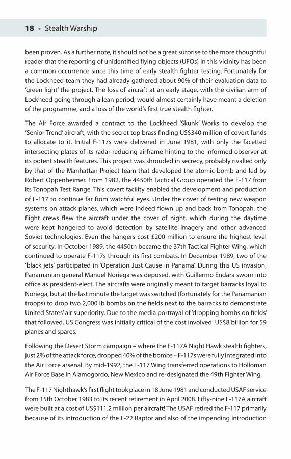
1. Materials should be incorporated into the ship’s superstructure and outside surfaces that have a very low radar refl ection coeffi cient, such as plastics, carbon composites or glass-reinforced plastic (GRP). Surprisingly perhaps Nelson’s fl agship HMS Victory, in spite of its extensive mast rigging (Figure 1.11), would have a relatively low RCS by modern ship standards!
2. RAMs – usually foams which can be overlaid with specialist paints – are also generally included where possible. Simple RAM cancels any threat or ‘enemy’ refl ected waves destructively with the application of quarter wavelength coatings. Multiple RAM layers, a little like the structured layering seen within plywood, can also be applied to provide destructive cancellation across a broader range of wavelengths. Surface paint may also add carbonyl iron ferrite spheres so that incoming radar waves induce alternating magnetic fi elds in the surface paint, converting radar energy into heat. This type of paint is often referred to as ‘iron ball’ paint. Conductive transparent coatings also allow the designer to have the fl exibility to introduce controlled shapes that can defl ect radar waves so that they do not even enter a ship’s bridge windows and then refl ect off in a diff erent direction away from the roving eyes of the enemy radar. Gold and transparent indium tin oxide (ITO) are also frequently used.
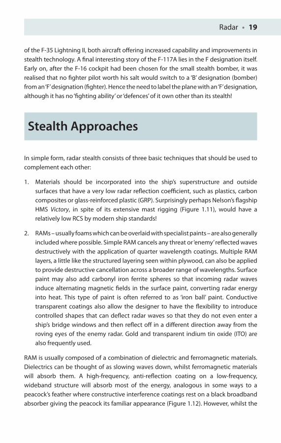
RAM is usually composed of a combination of dielectric and ferromagnetic materials. Dielectrics can be thought of as slowing waves down, whilst ferromagnetic materials will absorb them. A high-frequency, anti-refl ection coating on a low-frequency, wideband structure will absorb most of the energy, analogous in some ways to a peacock’s feather where constructive interference coatings rest on a black broadband absorber giving the peacock its familiar appearance (Figure 1.12). However, whilst the
20 • Stealth Warship
Figure 1.11 HMS Victory © CR Lavers
Figure 1.12 Peacock feather © CR Lavers
Radar • 21
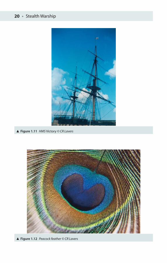
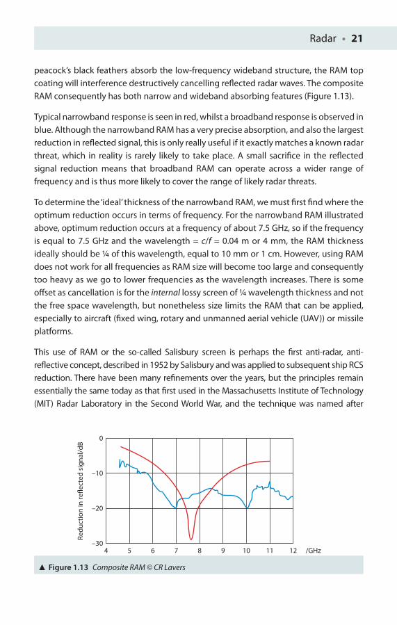
peacock’s black feathers absorb the low-frequency wideband structure, the RAM top coating will interference destructively cancelling refl ected radar waves. The composite RAM consequently has both narrow and wideband absorbing features (Figure 1.13).
Typical narrowband response is seen in red, whilst a broadband response is observed in blue. Although the narrowband RAM has a very precise absorption, and also the largest reduction in refl ected signal, this is only really useful if it exactly matches a known radar threat, which in reality is rarely likely to take place. A small sacrifi ce in the refl ected signal reduction means that broadband RAM can operate across a wider range of frequency and is thus more likely to cover the range of likely radar threats.
To determine the ‘ideal’ thickness of the narrowband RAM, we must fi rst fi nd where the optimum reduction occurs in terms of frequency. For the narrowband RAM illustrated above, optimum reduction occurs at a frequency of about 7.5 GHz, so if the frequency is equal to 7.5 GHz and the wavelength = c/f = 0.04 m or 4 mm, the RAM thickness ideally should be ¼ of this wavelength, equal to 10 mm or 1 cm. However, using RAM does not work for all frequencies as RAM size will become too large and consequently too heavy as we go to lower frequencies as the wavelength increases. There is some off set as cancellation is for the internal lossy screen of ¼ wavelength thickness and not the free space wavelength, but nonetheless size limits the RAM that can be applied, especially to aircraft (fi xed wing, rotary and unmanned aerial vehicle (UAV)) or missile platforms.
This use of RAM or the so-called Salisbury screen is perhaps the fi rst anti-radar, anti-refl ective concept, described in 1952 by Salisbury and was applied to subsequent ship RCS reduction. There have been many refi nements over the years, but the principles remain essentially the same today as that fi rst used in the Massachusetts Institute of Technology (MIT) Radar Laboratory in the Second World War, and the technique was named after
4–30
Redu
ctio
n in
refle
cted
sig
nal/d
B
–20
–10
0
5 6 7 8 9 10 11 12 /GHz
Figure 1.13 Composite RAM © CR Lavers
22 • Stealth Warship
him. This provides a simple way to use the resistive Ohmic loss mechanism in layered absorbers. The Salisbury screen consists of a sheet of resistive material, λ/4 thick, placed over a ‘ground plane’ (the metal bulkhead surface of the naval warship to be concealed); the quarter wavelength dielectric that will be absorbed; and a thin lossy screen. Magnetic loss mechanisms are intrinsically narrowband. To obtain more bandwidth, you need to use multiple layers of absorber separated by dielectric spacers, somewhat akin to a multilayer plywood structure indicated earlier, or modern multiple layer anti-refl ection coating. The isotropic dielectric constant of the spacers controls the maximum bandwidth of the design where the lower permittivity results in an increase in the working bandwidth. Foam and honeycomb spacers give a physically thick sandwich structure. To achieve a composite skin, you can use fi breglass and absorbing layers and even injection mould the whole thing as a complete carbon-fi bre composite as the structure will be heavily carbon impregnated anyway. In principle, from previous experimental research, the dielectric constant is actually a three-dimensional dielectric tensor confi guration, which means that there is the ability to tailor-make diff erent absorbing properties in the three principal axial directions [4, 5].
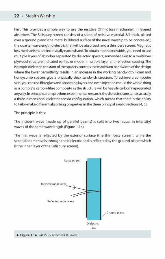
The principle is this:
The incident wave (made up of parallel beams) is split into two (equal in intensity) waves of the same wavelength (Figure 1.14).
The fi rst wave is refl ected by the exterior surface (the thin lossy screen), while the second beam travels through the dielectric and is refl ected by the ground plane (which is the inner layer of the Salisbury screen).
Lossy screen
Incident radar wave
Reflected radar wave
Ground plane
Dielectricλ/4
Figure 1.14 Salisbury screen © CR Lavers

Radar • 23
Ideally, if the magnitudes of both the refl ected waves are the same and the phases of the two waves are exactly out of phase, the two waves will interfere and cancel each other’s electric fi elds.
From interference theory, two waves that are coherent interact, and they will combine to form a single output wave. Furthermore, if the peaks coincide, the output intensity will be the sum of the two intensities. However, if the two waves are completely out-of-phase, both intensities cancel each other out (this happens when two waves are off set by half a wavelength). The second wave travels twice the distance (the path across to the ground plate and back towards the exterior thin lossy screen), for a total path distance of half a wavelength. Thus the two waves cancel each other, and nothing should be detected by the enemy radar receiver. Even if this is not quite achieved in practice, the residual level of signal energy should be well below that required to exceed the threshold of most search radar systems. High dielectric constant makes the wave paths travelling inside the material generally independent of angle of incidence so that one can get internal behaviour that is broadly the same as a function of exterior angle. The internal thickness required does not necessarily become too unwieldy in the fi rst instance as actual thickness required is equal to λ
o/(4√ε
R), where λ
o is the free space
wavelength and √εR the dielectric constant (permittivity) of the material itself.
There are some disadvantages with this quarter wavelength approach. First, Salisbury screens work well for only a narrow portion of the radar spectrum, making it vulnerable to multiple radar protected areas and indeed modern spread spectrum radar technology. Another possibility is the Dallenbach layer – a homogeneous lossy layer backed by a metal plate and two key multilayer systems: the Jaumann absorber and graded dielectric absorbers (materials with properties that vary across the layers like modern graded-index multimode optical fi bres). A second problem is the thickness of the screen itself; radar wavelengths are typically of 1 mm to 10 cm thickness, so at longer wavelengths, the thickness will indeed become unreasonably large. Because of the likely horizontal and distant nature of most seaborne search radar threats, and refraction eff ects (the signifi cant lowering of the speed of wave propagation), destructive interference is maintained over a wide angle range. There is considerable interest in developing tuneable microwave composite materials incorporating ferromagnetic microwires, which would have the potential advantage of being able to tune to the threat during the relatively long search pulses which are radiated and then maximise active cancellation [6].
3. Ship geometry is also a critical factor. So-called dihedrals and trihedrals (where two or three surfaces, respectively, meet together at 90°) must be eliminated at all costs. Both of these geometries will strongly refl ect radar energy over a wide angular range directly back to the search radar. Especially troublesome are the
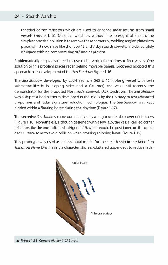
24 • Stealth Warship
trihedral corner refl ectors which are used to enhance radar returns from small vessels (Figure 1.15). On older warships, without the foresight of stealth, the simplest practical solution is to remove these corners by welding angled plates into place, whilst new ships like the Type 45 and Visby stealth corvette are deliberately designed with no compromising 90° angles present.
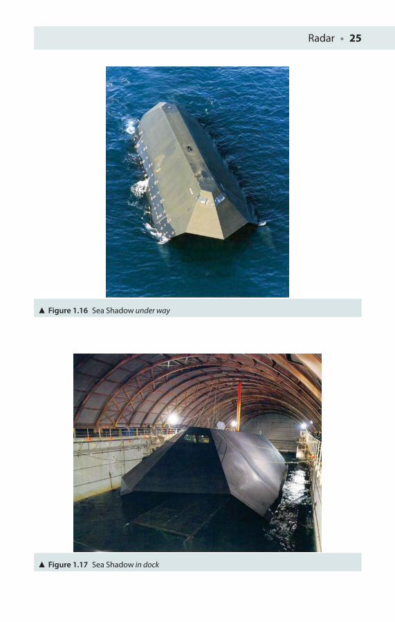
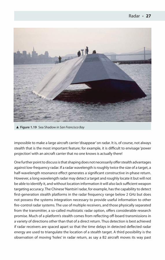
Problematically, ships also need to use radar, which themselves refl ect waves. One solution to this problem places radar behind movable panels. Lockheed adopted this approach in its development of the Sea Shadow (Figure 1.16).
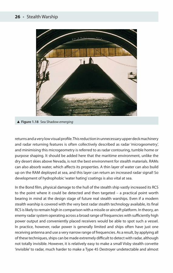
The Sea Shadow developed by Lockheed is a 563 t, 164 ft-long vessel with twin submarine-like hulls, sloping sides and a fl at roof, and was until recently the demonstrator for the proposed Northrop’s Zumwalt DDX Destroyer. The Sea Shadow was a ship test bed platform developed in the 1980s by the US Navy to test advanced propulsion and radar signature reduction technologies. The Sea Shadow was kept hidden within a fl oating barge during the daytime (Figure 1.17).
The secretive Sea Shadow came out initially only at night under the cover of darkness (Figure 1.18). Nonetheless, although designed with a low RCS, the vessel carried corner refl ectors like the one indicated in Figure 1.15, which would be positioned on the upper deck surface so as to avoid collision when crossing shipping lanes (Figure 1.19).
This prototype was used as a conceptual model for the stealth ship in the Bond fi lm Tomorrow Never Dies, having a characteristic less-cluttered upper deck to reduce radar
Radar beam
Trihedral surface
Figure 1.15 Corner refl ector © CR Lavers
Radar • 25
Figure 1.16 Sea Shadow under way
Figure 1.17 Sea Shadow in dock
26 • Stealth Warship
returns and a very low visual profi le. This reduction in unnecessary upper deck machinery and radar returning features is often collectively described as radar ‘microgeometry’, and minimising this microgeometry is referred to as radar contouring, tumble home or purpose shaping. It should be added here that the maritime environment, unlike the dry desert skies above Nevada, is not the best environment for stealth materials. RAMs can also absorb water, which aff ects its properties. A thin layer of water can also build up on the RAM deployed at sea, and this layer can return an increased radar signal! So development of hydrophobic ‘water hating’ coatings is also vital at sea.
In the Bond fi lm, physical damage to the hull of the stealth ship vastly increased its RCS to the point where it could be detected and then targeted – a practical point worth bearing in mind at the design stage of future real stealth warships. Even if a modern stealth warship is covered with the very best radar stealth technology available, its fi nal RCS is likely to remain high in comparison with a missile or aircraft platform. In theory, an enemy radar system operating across a broad range of frequencies with suffi ciently high power output and conveniently placed receivers would be able to spot such a vessel. In practice, however, radar power is generally limited and ships often have just one receiving antenna and use a very narrow range of frequencies. As a result, by applying all of these techniques, ships can be made extremely diffi cult to detect with radar, although not totally invisible. However, it is relatively easy to make a small Visby stealth corvette ‘invisible’ to radar, much harder to make a Type 45 Destroyer undetectable and almost
Figure 1.18 Sea Shadow emerging
Radar • 27
impossible to make a large aircraft carrier ‘disappear’ on radar. It is, of course, not always stealth that is the most important feature; for example, it is diffi cult to envisage ‘power projection’ with an aircraft carrier that no one knows is actually there!
One further point to discuss is that shaping does not necessarily off er stealth advantages against low-frequency radar. If a radar wavelength is roughly twice the size of a target, a half-wavelength resonance eff ect generates a signifi cant constructive in-phase return. However, a long wavelength radar may detect a target and roughly locate it but will not be able to identify it, and without location information it will also lack suffi cient weapon targeting accuracy. The Chinese ‘Nantsin’ radar, for example, has the capability to detect fi rst-generation stealth platforms in the radar frequency range below 2 GHz but does not possess the systems integration necessary to provide useful information to other fi re-control radar systems. The use of multiple receivers, and those physically separated from the transmitter, a so-called multistatic radar option, off ers considerable research promise. Much of a platform’s stealth comes from refl ecting off -board transmissions in a variety of directions other than that of a direct return. Thus detection is best achieved if radar receivers are spaced apart so that the time delays in detected defl ected radar energy are used to triangulate the location of a stealth target. A third possibility is the observation of moving ‘holes’ in radar return, as say a B2 aircraft moves its way past
Figure 1.19 Sea Shadow in San Francisco Bay
28 • Stealth Warship
the usual strong returns of a coastline or mountainous region, especially prominent if the aircraft were to be detected from an airborne radar itself at high altitude.
One key advantage of stealth that cannot be argued against is the benefi ts of stealth force package size as opposed to a conventional attack package. A conventional strike package will usually include a number of defence suppression aircraft, several fi ghter escorts and fuel tankers to support the activities of even one bomber versus a single stealth bomber. Conceived at the height of the Cold War’s tensions to outwit the Soviet enemy, this aircraft above all others put stealth, as it were, fi rmly on the ‘radar screen’ of new technologies. For further reading, a number of recent popular articles on stealth are included in the references, albeit with some personal bias [7, 8]!
Chapter Refl ections
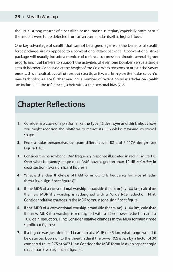
1. Consider a picture of a platform like the Type 42 destroyer and think about how you might redesign the platform to reduce its RCS whilst retaining its overall shape.
2. From a radar perspective, compare diff erences in B2 and F-117A design (see Figure 1.10).
3. Consider the narrowband RAM frequency response illustrated in red in Figure 1.8.Over what frequency range does RAM have a greater than 10 dB reduction in cross section (two signifi cant fi gures)?
4. What is the ideal thickness of RAM for an 8.5 GHz frequency India-band radar threat (two signifi cant fi gures)?
5. If the MDR of a conventional warship broadside (beam on) is 100 km, calculate the new MDR if a warship is redesigned with a 40 dB RCS reduction. Hint: Consider relative changes in the MDR formula (one signifi cant fi gure).
6. If the MDR of a conventional warship broadside (beam on) is 100 km, calculate the new MDR if a warship is redesigned with a 20% power reduction and a 10% gain reduction. Hint: Consider relative changes in the MDR formula (three signifi cant fi gures).
7. If a frigate was just detected beam on at a MDR of 45 km, what range would it be detected bows on to the threat radar if the bows RCS is less by a factor of 30 compared to its RCS at 90°? Hint: Consider the MDR formula as an aspect angle calculation (two signifi cant fi gures).
Radar • 29
References
1. Beard, J (2000), ‘Battle of Britain, 1940’, EyeWitness to History, www.eyewitnesstohistory.com.
2. Knott, E, Shaeff er, J and Tuley, M (1993), Radar Cross Section, 2nd ed. Norwood, MA: Artech house, p. 231. ISBN 0-890006-618-3.
3. http://en.wikipedia.org/wiki/Radar.
4. Lavers, CR (1991), ‘Optical mode characterisation of the confi guration of a thin ferroelectric liquid crystal cell under an applied electric fi eld’, Journal of Modern Optics, 38(8): 1451–1461.
5. Lavers, CR (1990), ‘The optical dielectric tensor confi guration in aligned ferroelectric liquid crystal cells’, PhD Thesis, University of Exeter, Exeter, UK.
6. Makhnovskiy, D, Zhukov, A, Zhukova, V and Gonzalez, J (2008), ‘Tunable and self-sensing microwave composite materials incorporating ferromagnetic microwires’, Advances in Science and Technology, 54: 201–210.
7. Lavers, CR (2008), ‘Stealthy materials’, Material World, December, pp. 33–35.
8. Lavers, CR (2008), ‘Invisibility rules the waves’, Physics World, March, pp. 21–25.
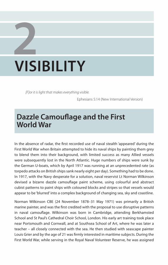
2VISIBILITY
[F]or it is light that makes everything visible.
Ephesians 5:14 (New International Version)
Dazzle Camoufl age and the First World War
In the absence of radar, the fi rst recorded use of naval stealth ‘appeared’ during the First World War when Britain attempted to hide its naval ships by painting them grey to blend them into their background, with limited success as many Allied vessels were subsequently lost in the North Atlantic. Huge numbers of ships were sunk by the German U-boats, which by April 1917 was running at an unprecedented rate (as torpedo attacks on British ships sank nearly eight per day). Something had to be done. In 1917, with the Navy desperate for a solution, naval reservist Lt Norman Wilkinson devised a bizarre dazzle camoufl age paint scheme, using colourful and abstract cubist patterns to paint ships with coloured blocks and stripes so that vessels would appear to be ‘blurred’ into a complex background of changing sea, sky and coastline.
Norman Wilkinson CBE (24 November 1878–31 May 1971) was primarily a British marine painter, and was the fi rst credited with the proposal to use disruptive patterns in naval camoufl age. Wilkinson was born in Cambridge, attending Berkhamsted School and St Paul’s Cathedral Choir School, London. His early art training took place near Portsmouth and Cornwall, and at Southsea School of Art, where he was later a teacher – all closely connected with the sea. He then studied with seascape painter Louis Grier and by the age of 21 was fi rmly interested in maritime subjects. During the First World War, while serving in the Royal Naval Volunteer Reserve, he was assigned
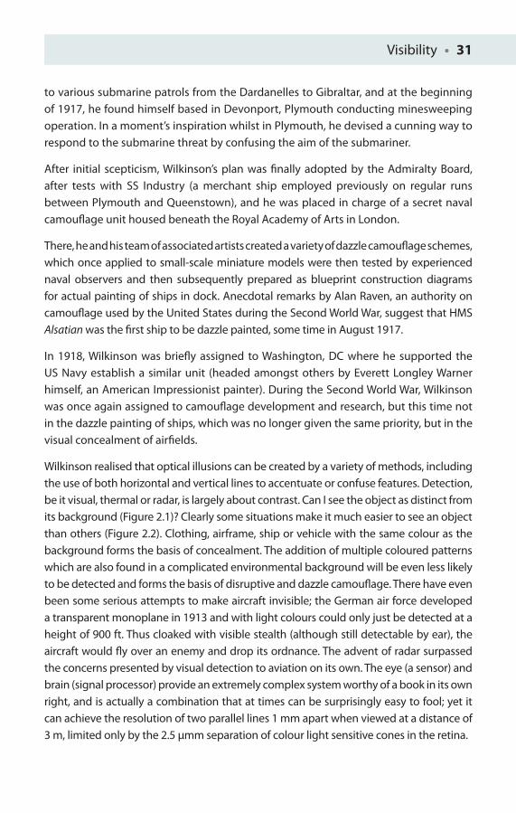
Visibility • 31
to various submarine patrols from the Dardanelles to Gibraltar, and at the beginning of 1917, he found himself based in Devonport, Plymouth conducting minesweeping operation. In a moment’s inspiration whilst in Plymouth, he devised a cunning way to respond to the submarine threat by confusing the aim of the submariner.
After initial scepticism, Wilkinson’s plan was fi nally adopted by the Admiralty Board, after tests with SS Industry (a merchant ship employed previously on regular runs between Plymouth and Queenstown), and he was placed in charge of a secret naval camoufl age unit housed beneath the Royal Academy of Arts in London.
There, he and his team of associated artists created a variety of dazzle camoufl age schemes, which once applied to small-scale miniature models were then tested by experienced naval observers and then subsequently prepared as blueprint construction diagrams for actual painting of ships in dock. Anecdotal remarks by Alan Raven, an authority on camoufl age used by the United States during the Second World War, suggest that HMS Alsatian was the fi rst ship to be dazzle painted, some time in August 1917.
In 1918, Wilkinson was briefl y assigned to Washington, DC where he supported the US Navy establish a similar unit (headed amongst others by Everett Longley Warner himself, an American Impressionist painter). During the Second World War, Wilkinson was once again assigned to camoufl age development and research, but this time not in the dazzle painting of ships, which was no longer given the same priority, but in the visual concealment of airfi elds.
Wilkinson realised that optical illusions can be created by a variety of methods, including the use of both horizontal and vertical lines to accentuate or confuse features. Detection, be it visual, thermal or radar, is largely about contrast. Can I see the object as distinct from its background (Figure 2.1)? Clearly some situations make it much easier to see an object than others (Figure 2.2). Clothing, airframe, ship or vehicle with the same colour as the background forms the basis of concealment. The addition of multiple coloured patterns which are also found in a complicated environmental background will be even less likely to be detected and forms the basis of disruptive and dazzle camoufl age. There have even been some serious attempts to make aircraft invisible; the German air force developed a transparent monoplane in 1913 and with light colours could only just be detected at a height of 900 ft. Thus cloaked with visible stealth (although still detectable by ear), the aircraft would fl y over an enemy and drop its ordnance. The advent of radar surpassed the concerns presented by visual detection to aviation on its own. The eye (a sensor) and brain (signal processor) provide an extremely complex system worthy of a book in its own right, and is actually a combination that at times can be surprisingly easy to fool; yet it can achieve the resolution of two parallel lines 1 mm apart when viewed at a distance of 3 m, limited only by the 2.5 μmm separation of colour light sensitive cones in the retina.
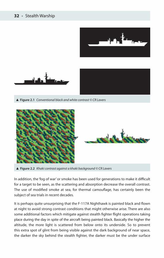
32 • Stealth Warship
In addition, the ‘fog of war’ or smoke has been used for generations to make it diffi cult for a target to be seen, as the scattering and absorption decrease the overall contrast. The use of modifi ed smoke at sea, for thermal camoufl age, has certainly been the subject of sea trials in recent decades.
It is perhaps quite unsurprising that the F-117A Nighthawk is painted black and fl own at night to avoid strong contrast conditions that might otherwise arise. There are also some additional factors which mitigate against stealth fi ghter fl ight operations taking place during the day in spite of the aircraft being painted black. Basically the higher the altitude, the more light is scattered from below onto its underside. So to prevent this extra spot of glint from being visible against the dark background of near space, the darker the sky behind the stealth fi ghter, the darker must be the under surface
Figure 2.1 Conventional black and white contrast © CR Lavers
Figure 2.2 Khaki contrast against a khaki background © CR Lavers
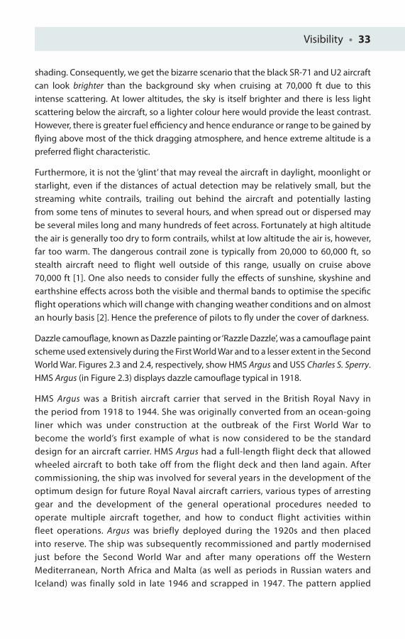
Visibility • 33
shading. Consequently, we get the bizarre scenario that the black SR-71 and U2 aircraft can look brighter than the background sky when cruising at 70,000 ft due to this intense scattering. At lower altitudes, the sky is itself brighter and there is less light scattering below the aircraft, so a lighter colour here would provide the least contrast. However, there is greater fuel effi ciency and hence endurance or range to be gained by fl ying above most of the thick dragging atmosphere, and hence extreme altitude is a preferred fl ight characteristic.
Furthermore, it is not the ‘glint’ that may reveal the aircraft in daylight, moonlight or starlight, even if the distances of actual detection may be relatively small, but the streaming white contrails, trailing out behind the aircraft and potentially lasting from some tens of minutes to several hours, and when spread out or dispersed may be several miles long and many hundreds of feet across. Fortunately at high altitude the air is generally too dry to form contrails, whilst at low altitude the air is, however, far too warm. The dangerous contrail zone is typically from 20,000 to 60,000 ft, so stealth aircraft need to fl ight well outside of this range, usually on cruise above 70,000 ft [1]. One also needs to consider fully the eff ects of sunshine, skyshine and earthshine eff ects across both the visible and thermal bands to optimise the specifi c fl ight operations which will change with changing weather conditions and on almost an hourly basis [2]. Hence the preference of pilots to fl y under the cover of darkness.
Dazzle camoufl age, known as Dazzle painting or ‘Razzle Dazzle’, was a camoufl age paint scheme used extensively during the First World War and to a lesser extent in the Second World War. Figures 2.3 and 2.4, respectively, show HMS Argus and USS Charles S. Sperry. HMS Argus (in Figure 2.3) displays dazzle camoufl age typical in 1918.
HMS Argus was a British aircraft carrier that served in the British Royal Navy in the period from 1918 to 1944. She was originally converted from an ocean-going liner which was under construction at the outbreak of the First World War to become the world’s first example of what is now considered to be the standard design for an aircraft carrier. HMS Argus had a full-length flight deck that allowed wheeled aircraft to both take off from the flight deck and then land again. After commissioning, the ship was involved for several years in the development of the optimum design for future Royal Naval aircraft carriers, various types of arresting gear and the development of the general operational procedures needed to operate multiple aircraft together, and how to conduct flight activities within fleet operations. Argus was briefly deployed during the 1920s and then placed into reserve. The ship was subsequently recommissioned and partly modernised just before the Second World War and after many operations off the Western Mediterranean, North Africa and Malta (as well as periods in Russian waters and Iceland) was finally sold in late 1946 and scrapped in 1947. The pattern applied
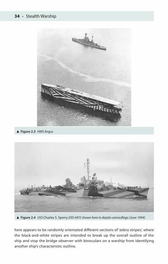
34 • Stealth Warship
Figure 2.3 HMS Argus
Figure 2.4 USS Charles S. Sperry (DD-697) shown here in dazzle camoufl age (June 1944)
here appears to be randomly orientated different sections of ‘zebra stripes’, where the black-and-white stripes are intended to break up the overall outline of the ship and stop the bridge observer with binoculars on a warship from identifying another ship’s characteristic outline.
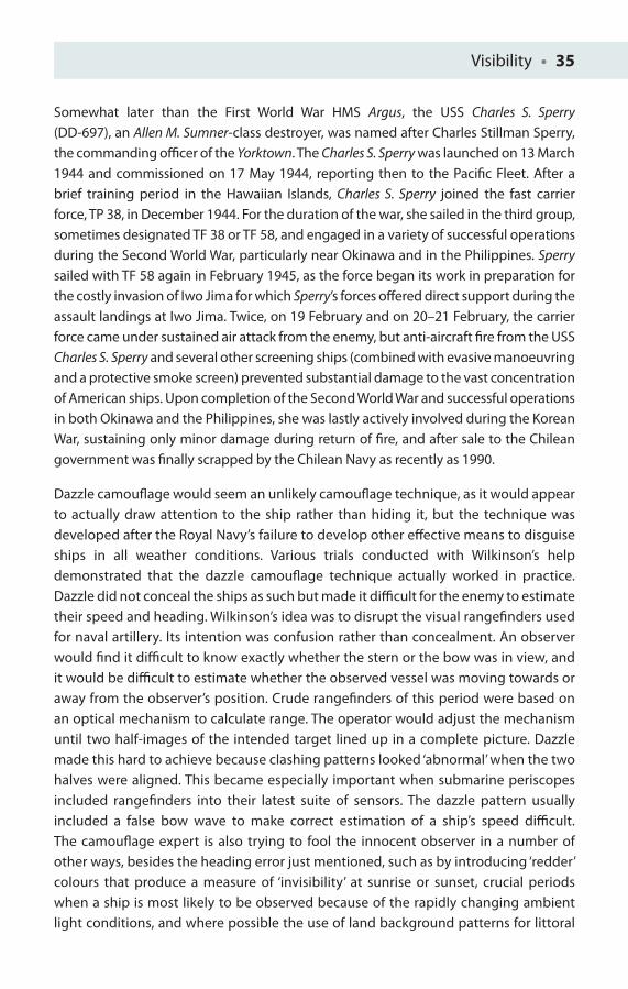
Visibility • 35
Somewhat later than the First World War HMS Argus, the USS Charles S. Sperry (DD-697), an Allen M. Sumner-class destroyer, was named after Charles Stillman Sperry, the commanding offi cer of the Yorktown. The Charles S. Sperry was launched on 13 March 1944 and commissioned on 17 May 1944, reporting then to the Pacifi c Fleet. After a brief training period in the Hawaiian Islands, Charles S. Sperry joined the fast carrier force, TP 38, in December 1944. For the duration of the war, she sailed in the third group, sometimes designated TF 38 or TF 58, and engaged in a variety of successful operations during the Second World War, particularly near Okinawa and in the Philippines. Sperry sailed with TF 58 again in February 1945, as the force began its work in preparation for the costly invasion of Iwo Jima for which Sperry’s forces off ered direct support during the assault landings at Iwo Jima. Twice, on 19 February and on 20–21 February, the carrier force came under sustained air attack from the enemy, but anti-aircraft fi re from the USS Charles S. Sperry and several other screening ships (combined with evasive manoeuvring and a protective smoke screen) prevented substantial damage to the vast concentration of American ships. Upon completion of the Second World War and successful operations in both Okinawa and the Philippines, she was lastly actively involved during the Korean War, sustaining only minor damage during return of fi re, and after sale to the Chilean government was fi nally scrapped by the Chilean Navy as recently as 1990.
Dazzle camoufl age would seem an unlikely camoufl age technique, as it would appear to actually draw attention to the ship rather than hiding it, but the technique was developed after the Royal Navy’s failure to develop other eff ective means to disguise ships in all weather conditions. Various trials conducted with Wilkinson’s help demonstrated that the dazzle camoufl age technique actually worked in practice. Dazzle did not conceal the ships as such but made it diffi cult for the enemy to estimate their speed and heading. Wilkinson’s idea was to disrupt the visual rangefi nders used for naval artillery. Its intention was confusion rather than concealment. An observer would fi nd it diffi cult to know exactly whether the stern or the bow was in view, and it would be diffi cult to estimate whether the observed vessel was moving towards or away from the observer’s position. Crude rangefi nders of this period were based on an optical mechanism to calculate range. The operator would adjust the mechanism until two half-images of the intended target lined up in a complete picture. Dazzle made this hard to achieve because clashing patterns looked ‘abnormal’ when the two halves were aligned. This became especially important when submarine periscopes included rangefi nders into their latest suite of sensors. The dazzle pattern usually included a false bow wave to make correct estimation of a ship’s speed diffi cult. The camoufl age expert is also trying to fool the innocent observer in a number of other ways, besides the heading error just mentioned, such as by introducing ‘redder’ colours that produce a measure of ‘invisibility’ at sunrise or sunset, crucial periods when a ship is most likely to be observed because of the rapidly changing ambient light conditions, and where possible the use of land background patterns for littoral
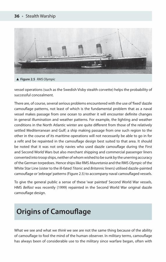
36 • Stealth Warship
vessel operations (such as the Swedish Visby stealth corvette) helps the probability of successful concealment.
There are, of course, several serious problems encountered with the use of ‘fi xed’ dazzle camoufl age patterns, not least of which is the fundamental problem that as a naval vessel makes passage from one ocean to another it will encounter defi nite changes in general illumination and weather patterns. For example, the lighting and weather conditions in the North Atlantic winter are quite diff erent from those of the relatively settled Mediterranean and Gulf; a ship making passage from one such region to the other in the course of its maritime operations will not necessarily be able to go in for a refi t and be repainted in the camoufl age design best suited to that area. It should be noted that it was not only navies who used dazzle camoufl age during the First and Second World Wars but also merchant shipping and commercial passenger liners converted into troop ships, neither of whom wished to be sunk by the unerring accuracy of the German torpedoes. Hence ships like RMS Mauretania and the RMS Olympic of the White Star Line (sister to the ill-fated Titanic and Britannic liners) utilised dazzle-painted camoufl age or ‘zebrage’ patterns (Figure 2.5) to accompany naval camoufl aged vessels.
To give the general public a sense of these ‘war painted’ Second World War vessels, HMS Belfast was recently (1999) repainted in the Second World War original dazzle camoufl age design.
Origins of Camoufl age
What we see and what we think we see are not the same thing because of the ability of camoufl age to fool the mind of the human observer. In military terms, camoufl age has always been of considerable use to the military since warfare began, often with
Figure 2.5 RMS Olympic

Visibility • 37
an element of deception added as well (ask King Priam or Gideon), but it defi nitely became a vital part of modern military tactics after the increase in accuracy and rate of fi re of weapons during the late nineteenth century. Despite the benefi ts of camoufl age, until the twentieth century armies still continued to wear very bright colours with bold designs, for a variety of reasons, including intimidation and to allow easier identifi cation of one’s own combat units in the ‘fog of war’. As discussed previously, the intention of camoufl age is to disrupt an outline by merging it into its surroundings, thus making a soldier on land or a ship at sea harder to spot and consequently harder to hit if detected and targeted. In nature camoufl age is a way of using protective colouration that will conceal an animal being distinguished from its surroundings by a predator. The reader is invited to look at the breadth of cryptic camoufl age and also its link to the principles of animal communication; for further detailed work on this subject, see Bradbury et al. [3].
In practice it is a soldier’s uniform which makes him indistinguishable from his surroundings. The British Army fi rst adopted khaki operationally in India after 1857, surprisingly late after their experiences in the American War of Independence where the red tunic made the typical English solider a highly visible target. The high casualty rate of the British in India forced them to dye their traditional red tunics to more neutral or drab tones, initially a muddy tan called ‘khaki’ from the Urdu word for mud. Similarly the Russian-Japanese War in 1905 led the Russian army to change their long-held views of visibility and developed a grey form of khaki. Likewise most of the world’s armies during this period took up a form of khaki that would best help them to use camoufl age eff ectively in their own particular environments. With the First World War, there was a fi nal end to elaborately bright and embellished uniforms, except for certain ceremonial duties. This was truly the commencement of the rise of khakis, particularly greys, browns and greens, which were introduced to match the demands of modern military operations, aff ecting everything that was worn.
Camoufl age became well established in land warfare by the end of the First World War and unlike naval camoufl age developed much further during the Second World War. The level of sophistication used then was such that camoufl age netting was even successfully deployed in North African Allied campaigns alongside various infl atable tank decoys to provide convincing troop deployment locations to confuse Rommel and mislead his German forces.
Current technology has facilitated the development of various computer-generated camoufl age schemes, for example, CAMOGEN [4], and there is considerable international collaboration in camoufl age, concealment and deception, including the development of thermal camoufl age to minimise heat detection [5]. As well as the use of vertical and horizontal lines is the use of splinter camoufl age, breaking up
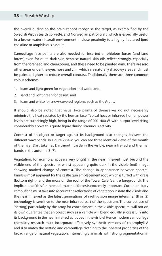
38 • Stealth Warship
the overall outline so the brain cannot recognise the target, as exemplifi ed by the Swedish Visby stealth corvette, and Norwegian patrol craft, which is especially useful in a brown water (littoral) environment in close proximity to a highly fractured fj ord coastline or amphibious assault.
Camoufl age face paints are also needed for inserted amphibious forces (and land forces) even for quite dark skin because natural skin oils refl ect strongly, especially from the forehead and cheekbones, and these need to be painted dark. There are also other areas under the eyes, nose and chin which are naturally shadowy areas and must be painted lighter to reduce overall contrast. Traditionally there are three common colour schemes:
1. loam and light green for vegetation and woodland,
2. sand and light green for desert, and
3. loam and white for snow-covered regions, such as the Arctic.
It should also be noted that visual face paints of themselves do not necessarily minimise the heat radiated by the human face. Typical heat or infra-red human power levels are surprisingly high, being in the range of 200–400 W, with output level rising considerably above this quote fi gure during strenuous activity.
Contrast of an object or target against its background also changes between the diff erent wavebands. In Figure 2.6a–c, you can see three identical views of the mouth of the river Dart taken at Dartmouth castle in the visible, near infra-red and thermal bands in the autumn [5–7].
Vegetation, for example, appears very bright in the near infra-red (just beyond the visible end of the spectrum), whilst appearing quite dark in the visible (red) image showing marked change of contrast. The change in appearance between spectral bands is most apparent for the castle gun emplacement roof, which is turfed with grass (bottom right), and the moss on the roof of the Tower Cafe (centre foreground). The implication of this for the modern armed forces is extremely important. Current military camoufl age must take into account the refl ectance of vegetation in both the visible and the near infra-red as the latest generations of night-vision image intensifi er (II or I2) technology is sensitive to the near infra-red part of the spectrum. The correct use of ‘netting’, particularly by the army for concealment in the visible spectrum, will not on its own guarantee that an object such as a vehicle will blend equally successfully into its background in the near infra-red as it does in the visible! Hence modern camoufl age chemistry research must incorporate eff ectively synthetic versions of chlorophyll A and B to match the netting and camoufl age clothing to the inherent properties of the broad range of natural vegetation. Interestingly animals with strong pigmentation in

Visibility • 39
the visible will also retain this characteristic in their skin well into the band of the near infra-red, as seen with the Hartmann’s zebra; Figure 2.7 [6, 7]
The strong refl ectance of vegetation in the near infra-red gives the image a characteristic ‘snowy’ appearance, but no snow is present in the image! Note with the zebra the orientation of stripes is at odds with the stripes from other parts of its body. It is imagined that in a herd of zebra, one individual animal’s disruptive pattern
(a)
(b)
(c)
Figure 2.6 River Dart taken in the (a) visible, (b) near infra-red and (c) infra-red thermal view © CR Lavers

40 • Stealth Warship
overlaps with a number of other animals and will not only provide a diffi cult time for predators to see them in the fi rst place but will also create a number of ‘virtual’ false targets at the critical time of committing an attack formed from overlapping ‘bits’ of several animals.
A simple contrast formula often used across any chosen spectral band, whether visible, near infra-red or thermal, is defi ned as follows:
Contrast = (target intensity − background intensity)
__________________________________ (target intensity + background intensity)
For example, if a thermal camera measures a target intensity of 0.5 W m–2 from a person at a range of 10 m, and the background intensity is 0.25 W m–2, the contrast = (0.5 – 0.25)/(0.5 + 0.25) = 0.25/0.75 = 1/3.
Contrast will usually range between 0 and +1 maximum positive change, and a minimum value of zero, found by substituting a background value equal to 0 or a background value equal to the target value, respectively. Maximum and minimum values can also be established by the use of diff erentiation.
Wilkinson used not only black-and-white patterns but also colourful cubist patterns (Figure 2.8) to confuse U-boat captains, denying speed and heading accuracy, with the possibility that broken outline patterns could prevent a human operator detecting a ship at all. Rapidly a team of artists painted over 4,000 merchant and naval vessels
Figure 2.7 Hartmann’s Zebra, Paignton Zoo © CR Lavers
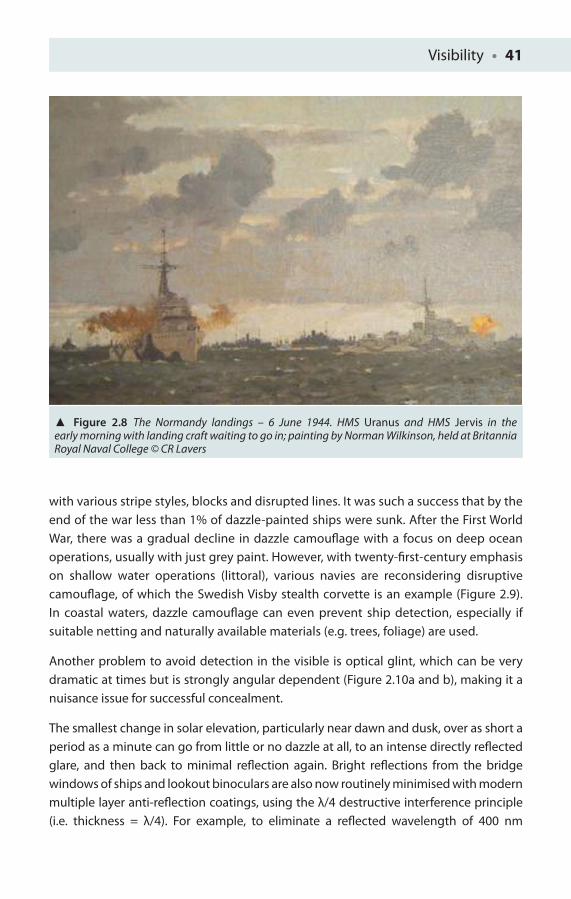
Visibility • 41
with various stripe styles, blocks and disrupted lines. It was such a success that by the end of the war less than 1% of dazzle-painted ships were sunk. After the First World War, there was a gradual decline in dazzle camoufl age with a focus on deep ocean operations, usually with just grey paint. However, with twenty-fi rst-century emphasis on shallow water operations (littoral), various navies are reconsidering disruptive camoufl age, of which the Swedish Visby stealth corvette is an example (Figure 2.9). In coastal waters, dazzle camoufl age can even prevent ship detection, especially if suitable netting and naturally available materials (e.g. trees, foliage) are used.
Another problem to avoid detection in the visible is optical glint, which can be very dramatic at times but is strongly angular dependent (Figure 2.10a and b), making it a nuisance issue for successful concealment.
The smallest change in solar elevation, particularly near dawn and dusk, over as short a period as a minute can go from little or no dazzle at all, to an intense directly refl ected glare, and then back to minimal refl ection again. Bright refl ections from the bridge windows of ships and lookout binoculars are also now routinely minimised with modern multiple layer anti-refl ection coatings, using the λ/4 destructive interference principle (i.e. thickness = λ/4). For example, to eliminate a refl ected wavelength of 400 nm
Figure 2.8 The Normandy landings – 6 June 1944. HMS Uranus and HMS Jervis in the early morning with landing craft waiting to go in; painting by Norman Wilkinson, held at Britannia Royal Naval College © CR Lavers
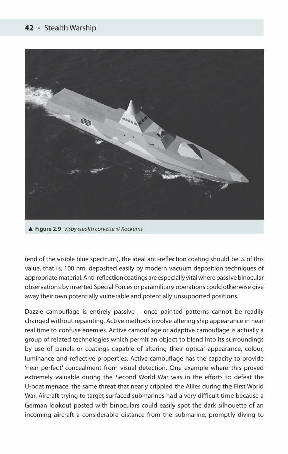
42 • Stealth Warship
(end of the visible blue spectrum), the ideal anti-refl ection coating should be ¼ of this value, that is, 100 nm, deposited easily by modern vacuum deposition techniques of appropriate material. Anti-refl ection coatings are especially vital where passive binocular observations by inserted Special Forces or paramilitary operations could otherwise give away their own potentially vulnerable and potentially unsupported positions.
Dazzle camoufl age is entirely passive – once painted patterns cannot be readily changed without repainting. Active methods involve altering ship appearance in near real time to confuse enemies. Active camoufl age or adaptive camoufl age is actually a group of related technologies which permit an object to blend into its surroundings by use of panels or coatings capable of altering their optical appearance, colour, luminance and refl ective properties. Active camoufl age has the capacity to provide ‘near perfect’ concealment from visual detection. One example where this proved extremely valuable during the Second World War was in the eff orts to defeat the U-boat menace, the same threat that nearly crippled the Allies during the First World War. Aircraft trying to target surfaced submarines had a very diffi cult time because a German lookout posted with binoculars could easily spot the dark silhouette of an incoming aircraft a considerable distance from the submarine, promptly diving to
Figure 2.9 Visby stealth corvette © Kockums
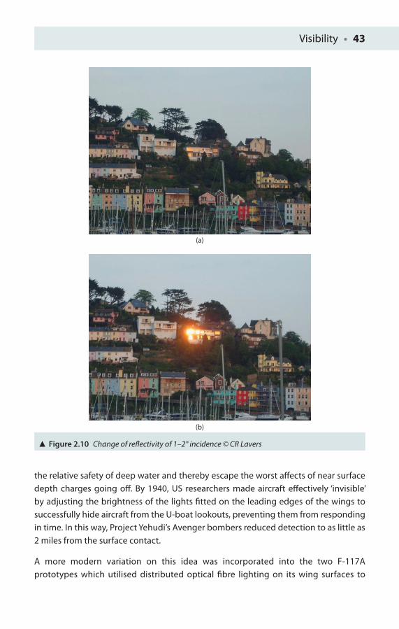
Visibility • 43
the relative safety of deep water and thereby escape the worst aff ects of near surface depth charges going off . By 1940, US researchers made aircraft eff ectively ‘invisible’ by adjusting the brightness of the lights fi tted on the leading edges of the wings to successfully hide aircraft from the U-boat lookouts, preventing them from responding in time. In this way, Project Yehudi’s Avenger bombers reduced detection to as little as 2 miles from the surface contact.
A more modern variation on this idea was incorporated into the two F-117A prototypes which utilised distributed optical fi bre lighting on its wing surfaces to
(a)
(b)
Figure 2.10 Change of refl ectivity of 1–2° incidence © CR Lavers
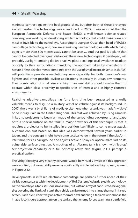
44 • Stealth Warship
minimise contrast against the background skies, but after both of these prototype aircraft crashed the technology was abandoned. In 2005, it was reported that the European Aeronautic Defence and Space (EADS), a well-known defence-related company, was working on developing similar technology that could make planes or missiles invisible to the naked eye. According to Juergen Kruse, then head of EADS’s camoufl age technology unit, ‘We are examining new technologies with which fl ying objects more than 800 metres away cannot be seen … And our goal is a plane that cannot be detected over great distances.’ These new technologies, if developed, will probably use light-emitting diodes or active plastic coatings to allow planes to adapt optically to their surroundings, mimicking the approach taken by chameleons in nature. These developments combined with the use of small micro air vehicles (MAVs) will potentially provide a revolutionary new capability for both tomorrow’s war fi ghters and other possible civilian applications, especially in urban environments. Their combination of small size and high manoeuvrability should enable them to operate within close proximity to specifi c sites of interest and in highly cluttered environments.
Real-time adaptive camoufl age has for a long time been suggested as a really valuable means to disguise a military vessel or vehicle against its background. In 2007, there was a brief fl urry of media excitement when a tank was made ‘invisible’ on Salisbury Plain in the United Kingdom. This feat was achieved by using cameras linked to projectors to beam an image of the surrounding background landscape onto a special surface on the tank. A major drawback of this technique is that it requires a projector to be installed in a position itself likely to come under attack. A chameleon suit based on this idea was demonstrated several years earlier in Japan, and the concept might have some tactical value in the future if the platform itself monitors its background and adjusts active displays or optical materials on its vulnerable surface direction. A mock-up of an Abrams tank is shown with ‘laptop’ self-projection capability or a full optically active skin (Figure 2.11), perhaps a practical option.
The Visby, already a very stealthy corvette, would be virtually invisible if this approach were applied, but would still possess a signifi cantly visible wake at high speed, as seen in Figure 2.12.
Developments in infra-red electronic camoufl age are perhaps further ahead of their visible counterparts with the development of BAE Systems’ Adaptiv stealth technology. To the naked eye, a tank still looks like a tank, but with an array of hand-sized, hexagonal tiles covering the fl anks of a tank the vehicle can be turned into a large thermal infra-red screen. Each tile is eff ectively an active thermal pixel enabling a tank crew to choose the image it considers appropriate on the tank so that enemy forces scanning a battlefi eld
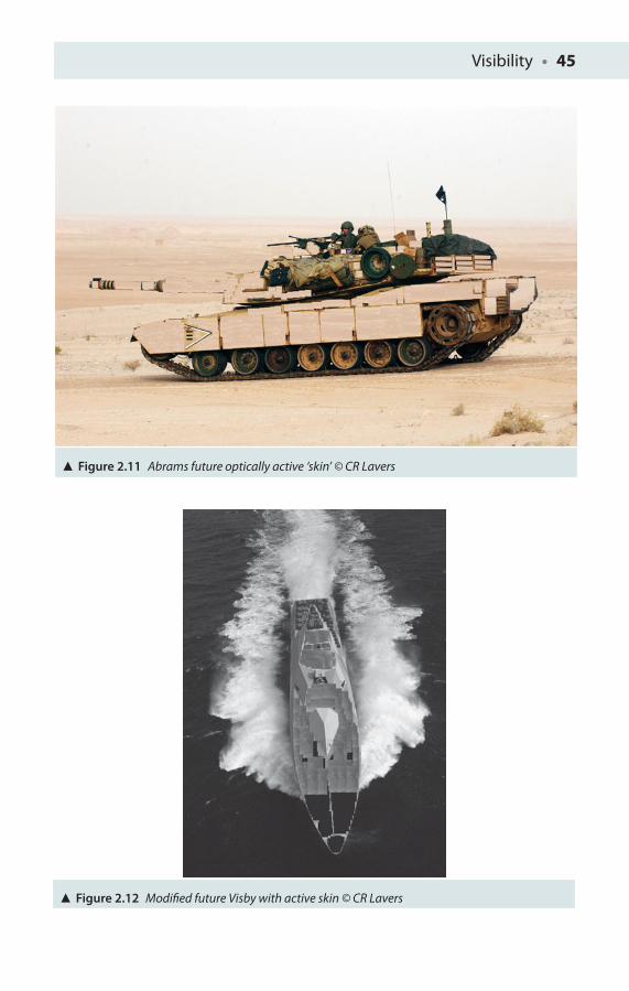
Visibility • 45
Figure 2.11 Abrams future optically active ‘skin’ © CR Lavers
Figure 2.12 Modifi ed future Visby with active skin © CR Lavers
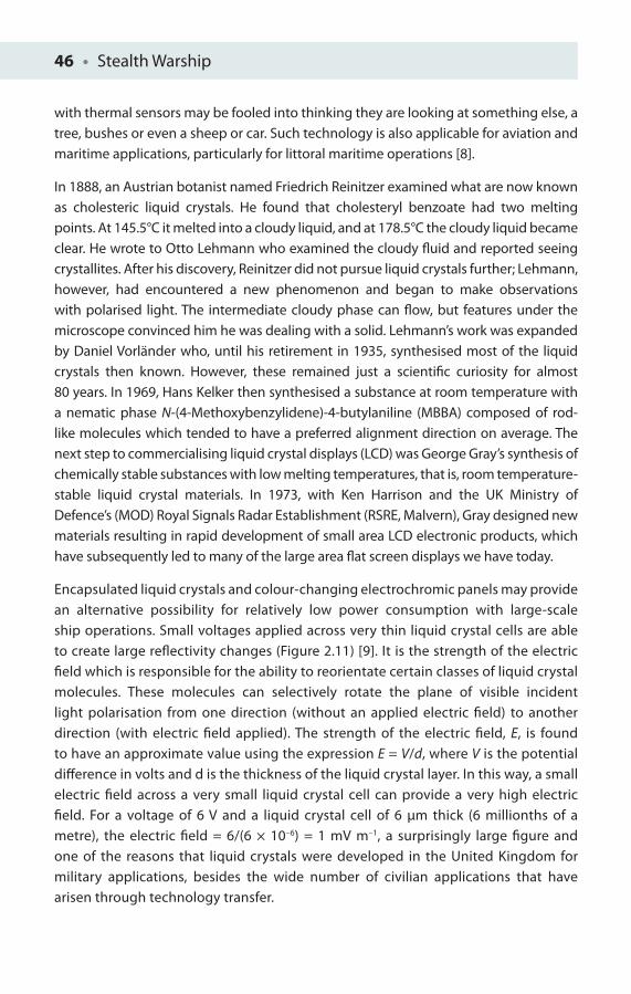
46 • Stealth Warship
with thermal sensors may be fooled into thinking they are looking at something else, a tree, bushes or even a sheep or car. Such technology is also applicable for aviation and maritime applications, particularly for littoral maritime operations [8].
In 1888, an Austrian botanist named Friedrich Reinitzer examined what are now known as cholesteric liquid crystals. He found that cholesteryl benzoate had two melting points. At 145.5°C it melted into a cloudy liquid, and at 178.5°C the cloudy liquid became clear. He wrote to Otto Lehmann who examined the cloudy fl uid and reported seeing crystallites. After his discovery, Reinitzer did not pursue liquid crystals further; Lehmann, however, had encountered a new phenomenon and began to make observations with polarised light. The intermediate cloudy phase can fl ow, but features under the microscope convinced him he was dealing with a solid. Lehmann’s work was expanded by Daniel Vorländer who, until his retirement in 1935, synthesised most of the liquid crystals then known. However, these remained just a scientifi c curiosity for almost 80 years. In 1969, Hans Kelker then synthesised a substance at room temperature with a nematic phase N-(4-Methoxybenzylidene)-4-butylaniline (MBBA) composed of rod-like molecules which tended to have a preferred alignment direction on average. The next step to commercialising liquid crystal displays (LCD) was George Gray’s synthesis of chemically stable substances with low melting temperatures, that is, room temperature-stable liquid crystal materials. In 1973, with Ken Harrison and the UK Ministry of Defence’s (MOD) Royal Signals Radar Establishment (RSRE, Malvern), Gray designed new materials resulting in rapid development of small area LCD electronic products, which have subsequently led to many of the large area fl at screen displays we have today.
Encapsulated liquid crystals and colour-changing electrochromic panels may provide an alternative possibility for relatively low power consumption with large-scale ship operations. Small voltages applied across very thin liquid crystal cells are able to create large refl ectivity changes (Figure 2.11) [9]. It is the strength of the electric fi eld which is responsible for the ability to reorientate certain classes of liquid crystal molecules. These molecules can selectively rotate the plane of visible incident light polarisation from one direction (without an applied electric fi eld) to another direction (with electric fi eld applied). The strength of the electric fi eld, E, is found to have an approximate value using the expression E = V/d, where V is the potential diff erence in volts and d is the thickness of the liquid crystal layer. In this way, a small electric fi eld across a very small liquid crystal cell can provide a very high electric fi eld. For a voltage of 6 V and a liquid crystal cell of 6 μm thick (6 millionths of a metre), the electric fi eld = 6/(6 × 10–6) = 1 mV m–1, a surprisingly large fi gure and one of the reasons that liquid crystals were developed in the United Kingdom for military applications, besides the wide number of civilian applications that have arisen through technology transfer.
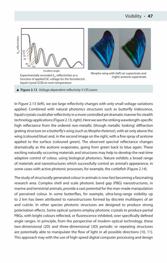
Visibility • 47
In Figure 2.13 (left), we see large refl ectivity changes with only small voltage variations applied. Combined with natural photonics structures such as butterfl y iridescence, liquid crystals could alter refl ectivity in a more controlled yet dramatic manner for stealth technology applications (Figure 2.13, right). Here we see the striking wavelength-specifi c high refl ectance from the ordered non-metallic (though metallic looking) diff raction grating structure on a butterfl y’s wing (such as Morpho rhetenor), with air only above the wing (coloured blue) and, in the second image on the right, with a fi ne spray of acetone applied to the surface (coloured green). The observed spectral refl ectance changes dramatically as the acetone evaporates, going from green back to blue again. These exciting naturally occurring materials and structures may help to develop the real-time adaptive control of colour, using biological photonics. Nature exhibits a broad range of materials and nanostructures which successfully control an animal’s appearance, in some cases with active photonic processes, for example, the cuttlefi sh (Figure 2.14).
The study of structurally generated colour in animals is now fast becoming a fascinating research area. Complex shell and scale photonic band gap (PBG) nanostructures, in marine and terrestrial animals, provide a vast potential for the man-made manipulation of perceived colour. In some butterfl ies, for example, ultra-long-range visibility up to 2 km has been attributed to nanostructures formed by discrete multilayers of air and cuticle. In other species photonic structures are designed to produce strong polarisation eff ects. Some optical systems employ photonic crystals to produce partial PBGs, with bright colours refl ected, or fl uorescence inhibited, over specifi cally defi ned angle ranges. In principle, from the perspective of modern optical technology, these two-dimensional (2D) and three-dimensional (3D) periodic or repeating structures are potentially able to manipulate the fl ow of light in all possible directions [10, 11]. This approach may with the use of high-speed digital computer processing and design
Incident angle
Experimentally recorded RSS reflectivities as afunction of applied DC voltage for the ferroelectricliquid crystal SCE8 at room temperature
Morpho wing with (left) air superstrate and(right) acetone superstrate
0V2V4V6V
8V10V 12V
R SS r
eflec
tiviti
es
Figure 2.13 Voltage dependent refl ectivity © CR Lavers
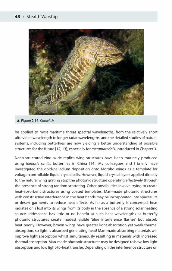
48 • Stealth Warship
be applied to most maritime threat spectral wavelengths, from the relatively short ultraviolet wavelength to longer radar wavelengths, and the detailed studies of natural systems, including butterfl ies, are now yielding a better understanding of possible structures for the future [12, 13], especially for metamaterials, introduced in Chapter 3.
Nano-structured zinc oxide replica wing structures have been routinely produced using Ideopsis similis butterfl ies in China [14]. My colleagues and I briefl y have investigated the gold/palladium deposition onto Morpho wings as a template for voltage-controllable liquid crystal cells. However, liquid crystal layers applied directly to the natural wing grating stop the photonic structure operating eff ectively through the presence of strong random scattering. Other possibilities involve trying to create heat-absorbent structures using coated templates. Man-made photonic structures with constructive interference in the heat bands may be incorporated into spacesuits or desert garments to reduce heat eff ects. As far as a butterfl y is concerned, heat radiates or is lost into its wings from its body in the absence of a strong solar heating source. Iridescence has little or no benefi t at such heat wavelengths as butterfl y photonic structures create modest visible ‘blue interference fl ashes’ but absorb heat poorly. However, brown wings have greater light absorption yet weak thermal absorption, so light is absorbed generating heat! Man-made absorbing materials will improve light absorption whilst simultaneously resulting in materials with increased thermal absorption. Man-made photonic structures may be designed to have low light absorption and low light-to-heat transfer. Depending on the interference structure on
Figure 2.14 Cuttlefi sh
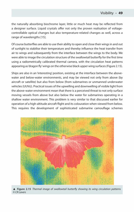
Visibility • 49
the naturally absorbing biochrome layer, little or much heat may be refl ected from a designer surface. Liquid crystals off er not only the proven realisation of voltage-controllable optical changes but also temperature-related changes as well, across a range of wavelengths [15].
Of course butterfl ies are able to use their ability to open and close their wings in and out of sunlight to stabilise their temperature and thereby infl uence the heat transfer from air to wings and subsequently from the interface between the wings to the body. We were able to image the circulation structure of the swallowtail butterfl y for the fi rst time using a radiometrically calibrated thermal camera, with the circulation heat patterns appearing as ‘dragon fl y’ wings on the otherwise black upper wing surfaces (Figure 2.15).
Ships are also in an ‘interesting’ position, existing at the interface between the above-water and below-water environments, and may be viewed not only from above (by aircraft or satellite) but also from below (from submarines or unmanned underwater vehicles (UUVs)). Practical issues of the upwelling and downwelling of visible light from the above-water environment mean that there is a perceived threat to not only surface moving vessels from above but also below the water for submarines operating in a shallow water environment. This problem is very similar to that discussed earlier for operation of a high-altitude aircraft fl ight and its colouration when viewed from below. This requires the development of sophisticated submarine camoufl age schemes
Figure 2.15 Thermal image of swallowtail butterfl y showing its wing circulation patterns © CR Lavers
50 • Stealth Warship
for littoral operations in a similar way that the Visby stealth corvette has adapted its paint schemes to refl ect their unique operations amongst complex fj ord coastlines. Most underwater camoufl age schemes experimented with to date tend to involve a combination of blue-and-black stripe confi gurations, red being a wavelength that is rapidly attenuated or reduced in even moderate depth of water.
Chapter Refl ections
1. Consider the visible target square seen below against its background. If contrast C = (a − b)/(a + b), where a is the target intensity, I
t = 1.5 W m–2, and b is
the background intensity, Ib = 1.0 W m–2, what is the value of the contrast (one
decimal place)? What are the conditions for maximum and minimum contrast? Suggest ways in which the contrast may change.
2. Consider the strong markings on the Hartmann’s zebra in Figure 2.7 in the near infra-red. What consequences do these near infra-red spectrum and visible absorptions have in the far infra-red? What are the implications of this for military operations?
3. Calculate the maximum relative change in refl ectivity between 0 and 10 V applied across the liquid crystal electro-optical device illustrated in Figure 2.13 for various incident angles. Does the angle of incidence make a signifi cant diff erence to this relative change?
4. For a thickness of 10 μm and an applied voltage of 12 V, what is the magnitude of the electric fi eld produced (two signifi cant fi gures)?
5. For a near infra-red wavelength of 900 nm, what is the ideal thickness for a transparent coating of indium tin oxide to minimise any refl ected infra-red (three signifi cant fi gures)?

Visibility • 51
References
1. Sweetman, B (2004), Lockheed Stealth. San Jose, CA: Zenith Press.
2. Shripad P Mahulikar et al 2009 ‘Study of sunshine, skyshine, and earthshine for aircraft infrared detection’, J. Opt. A: Pure Appl. Opt. 11, 045703.
3. Bradbury, JW and Vehrencamp, SL (1998), Principles of Animal Communication. Sunderland, MA: Sinauer.
4. Stroud, C, Sutherland, R, Wilson, M and Filbee, D (2005), ‘CAMOGEN – A method for generating optimized camoufl age schemes’, Journal of Defence Science, 10(1): 10–17. Unlimited theme paper.
5. Olsen, FB (2005), Methods for evaluating thermal camoufl age. Norwegian Defence Research Establishment, Kjeller, conference paper, 33 pages, approved for public release, report number: A946654.
6. Lavers, C, Franks, K, Floyd, M and Plowman, A (2005), ‘Application of remote thermal imaging and night vision technology to improve endangered wildlife resource management with minimal animal distress and hazard to humans’, Journal of Physics: Conference Series, 15: 207–212. Sensors and Their Applications XIII.
7. Lavers, C, Franks, K, Floyd, M and Plowman, A (2005), ‘Application of remote far infra red thermal imaging and night vision technology to improve endangered wildlife resource management with minimal animal distress and hazard to humans’, Proceedings of the Remote Sensing and Photogrammetry Society Annual Conference, with the NERC Earth Observation Conference, ‘Measuring, Mapping and Managing a Hazardous World’, 6–9 September, Portsmouth University, Portsmouth, UK.
8. Michell, S (2011), ‘The Invisibility Cloak’, Rusi Defence Systems, autumn/winter, pp. 80–81.
9. Lavers, CR (2008), ‘Stealthy materials’, Material World, December, pp. 33–35. Institute of Materials.
10. Krauss, TF, DeLaRue, RM and Brand, S (1996), ‘Two-dimensional photonic-bandgap structures operating at near-infrared wavelengths’, Nature, 383(6602): 699–702.
11. Russell, P St J (2003), ‘Photonic crystal fi bres’, Science, 299(5605): 358–362. (Review article.)
12. Vukusic, P and Sambles, JR (2003), ‘Photonic structures in biology’ (PDF), Nature, 424(6950): 852–855.
13. Kinoshita, S, Yoshioka, S and Kawagoe, K (2002), ‘Mechanisms of structural colour in the 3Morpho butterfl y: Cooperation of regularity and irregularity’ (PDF), Proceedings of the Royal Society B: Biological Sciences, 269(1499): 1417–1421.
14. Zhang, W, Zhang, D, Fan, T, Ding, J, Gu, J, Guo, Q and Ogawa, H (2006), ‘Biomimetic zinc oxide replica with structural colour using butterfl y (Ideopsis similis) wings as templates’, Bioinspiration & Biomimetics, 1(3): 89–95.
15. Lavers, CR (1991), ‘Wavelength characterisation of ferroelectric liquid crystal cells’, Japanese Journal of Applied Physics, 30(4): 729–734.
3INVISIBLE FUTURES
‘I will take the Ring’, he said, ‘though I do not know the way’.
Frodo, ‘The Council of Elrond’ from The Lord of the Rings, JRR Tolkien
Active ‘cloaking’ plasma shields may protect naval warships in the not so distant future. Certainly Soviet aircraft plasma antennae are known already to have the ability to substantially reduce radar refl ections, defl ecting waves around combat aerial platforms. Plasma antennae, like commonplace neon lights, do not refl ect radar energy when switched off . Consequently they are very stealthy, unlike some of the older and large refl ecting metal radar systems used by the Royal Navy during the Falklands Confl ict. When a radio-frequency (RF) electric pulse is applied to one end of a neon tube, the energy from the RF pulse ionises the gas molecules inside the tube to produce plasma which can strip away the outermost electrons from their parent atoms. The high electron density of these relatively mobile (or ‘free’) electrons within this plasma makes it an excellent conductor of electricity, just like a metal, whilst in this energised state, the enclosed plasma can readily radiate, absorb or refl ect electromagnetic (EM) waves. However, unlike a metal refl ector, once the applied voltage across the plasma device (or neon tube) is switched off again, the plasma very rapidly returns to being a neutral gas (or mixture of gases), and the antenna, in eff ect, disappears. It has been suggested that plasmas could form the basis of a compact and stealthy upgrade to the heavy, bulkhead-mounted, metallic phased array radars used today on the US Navy’s Aegis cruisers and other vessels, and some American work has been reported in this area.
Despite the obvious technical diffi culties of designing an actual plasma stealth device for modern combat aircraft, there are already claims that such a system has already been created, achieving some degree of stealth success in Russia from as early as 1999. In January 1999, the Russian ITAR-TASS news agency published an apparent interview with doctor Anatoliy Koroteyev, director of the Keldysh Research Centre (FKA Scientifi c

Invisible Futures • 53
Research Institute for Thermal Processes), where he talked in some detail about a plasma stealth device developed by his own organisation. The Institute for Thermal Processes is one of the top scientifi c research organisations in the world in the fi eld of fundamental physics, and his comments cannot be quickly dismissed or discounted. The Journal of Electronic Defense reported that ‘plasma-cloud-generation technology for stealth applications’ which had been developed in Russia could reduce an aircraft’s radar cross section (RCS) by a factor of 100.
According to this June 2002 article, the Russian plasma stealth device was reputed to have been tested previously in test fl ights onboard a Sukhoi Su-27 IB fi ghter-bomber, reporting that similar research into applications of plasma for RCS reduction was also at that time being carried out by Accurate Automation Corporation (Chattanooga, Tennessee) and Old Dominion University (Norfolk, Virginia) in the United States, and by Dassault Aviation (Saint-Cloud, France) and Thales (Paris, France). The Sukhoi Su-27 is a twin-engine manoeuvrable fi ghter aircraft intended as a direct competitor against American fourth-generation fi ghters, with a 3,530 km range or endurance, heavy armament, sophisticated avionics and quoted high manoeuvrability. The Su-27 most often fl ies air superiority missions, but can perform almost all combat roles. The Su-27’s closest US counterpart is realistically the F-15 Eagle.
Plasma, like the earth’s magnetosphere (which is a magnetic shield around the earth protecting it from solar fl ares and harmful radiation storms), could generate invisible shields extending around a ship’s exposed upper surfaces, also protecting it from advanced particle beam weapons and high-energy RF weapon systems currently under development. Particle beams are essentially near-light-speed weapons and are much more diffi cult to control and point than laser weapons. Particle beams are strictly a line-of-sight device and once fi red cannot be redirected.
Particle beam research work is ongoing at various laboratories worldwide, in particular at the Sandia National Laboratories, Los Alamos National Laboratories, Kirtland Air Force Base (AFB) and the White Sands Test Range in the United States. There are several reasons for the interest in particle beam and laser weapons, as they are both able to deliver all their energy directly onto the intended target. Second, they do not waste signifi cant energy on having to deliver a conventional missile only a small percentage of which will be the actual explosive ordnance. Third, the speed of fl ight is so rapid that even if the initial ‘fi ring’ is off -target, the target can within seconds be exactly aligned along the targeting bore-sight.
Although plasma antenna technology is still in its infancy, the US Navy has been working on developing plasma antenna systems for almost two decades. It was certainly hoped that plasmas could form the basis of a stealthy upgrade to the heavy
54 • Stealth Warship
Aegis passive phased array radar. Microwave beams from these arrays of antenna elements can be steered electronically towards multiple targets whilst still conducting search, navigation and other radar operations. Such a radar is said to be multifunctional because it can perform several diff erent tasks at the same time. It was believed that such plasma antenna technology controlled by strong magnetic fi elds would create a more precisely focused microwave beam technology. However, to function well, the resulting beams needed to be steered accurately in two dimensions, and this was not achieved, so the US Navy fi nally cancelled the research programme. Current upgrades are likely to be based around the use of lighter active phased array systems such as the Sampson radar on the Royal Navy’s latest stealthy Type 45 warship, which has been evaluated at White Sands Missile Base in America for upgrade suitability.
Radar Metamaterials
In the future, invisibility may become possible in certain specifi c narrow parts of the EM spectrum. David Smith at Duke University, Durham recently demonstrated the fi rst microwave invisibility ‘cloak’, leading to the intriguing possibility that perhaps one day very soon a radar cloak could be developed that will prevent an enemy radar seeing metallic objects, using metamaterials that could hide ships or missiles from enemy radar [1]. Metamaterials are a very recent but exciting area of research around the world. Metamaterial-engineered composites are tailored to have EM properties not found in nature, and they share many similarities with photonic crystals, which have periodic structures that permit only certain wavelengths to pass through them whilst preventing others. Metamaterials are artifi cial composite materials exhibiting extraordinary physical properties which are not observed in natural materials and have a huge potential for military and civilian optical and acoustic stealth applications. Unlike photonic crystals, metamaterial features are much smaller than the functional wavelength the cloak is intended to operate at (Figure 3.1).
So-called artifi cial ‘meta-atoms’ are sub-wavelength resonators and have a size of λ/10 or less, so the metamaterial medium appears to be uniform or homogeneous at the wavelength scale. If materials are considered to be either metals (conducting) or dielectric (insulating), an interesting representation can be given and plotted as a function of magnetic permeability and electric permittivity (Figure 3.2).
It is useful to defi ne the meaning of ‘dielectric’, ‘permeability’ and ‘permittivity’ at this point. A dielectric is an electrical insulator that can be polarised by an applied electric
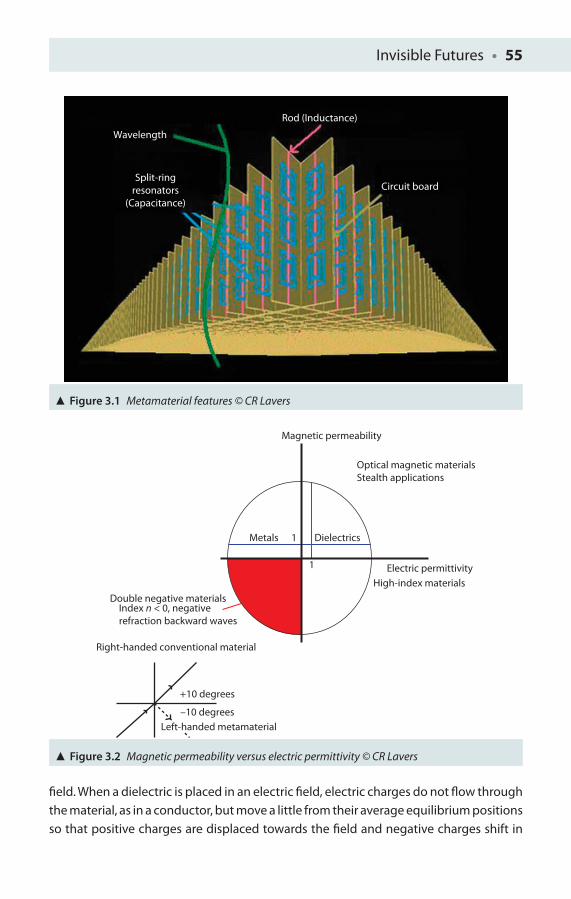
Invisible Futures • 55
Wavelength
Rod (Inductance)
Circuit boardSplit-ring
resonators(Capacitance)
Figure 3.1 Metamaterial features © CR Lavers
Figure 3.2 Magnetic permeability versus electric permittivity © CR Lavers
Magnetic permeability
Optical magnetic materialsStealth applications
Metals Dielectrics
Electric permittivityHigh-index materials
Double negative materials
Right-handed conventional material
+10 degrees
–10 degrees
Index n < 0, negativerefraction backward waves
1
1
Left-handed metamaterial
fi eld. When a dielectric is placed in an electric fi eld, electric charges do not fl ow through the material, as in a conductor, but move a little from their average equilibrium positions so that positive charges are displaced towards the fi eld and negative charges shift in
56 • Stealth Warship
the opposite direction. In electromagnetism, absolute permittivity is a measure of how an electric fi eld aff ects, and also is aff ected by, a dielectric medium. The permittivity (ε) of a medium describes how much electric fi eld (or fl ux) is ‘generated’ per unit charge. Less electric fl ux will exist in a medium with a high permittivity (per unit charge) due to polarisation eff ects. Hence, permittivity refl ects a material’s ability to transmit (or ‘permit’) an electric fi eld to pass through the medium. In SI units, permittivity, ε, is measured in farads per metre (F m–1), ε = ε
rε
0, where ε
r is the relative permittivity of the
material and ε0 = 8.85 × 10⁻¹² F m–1 is the vacuum permittivity. Similarly permeability
explains a material’s ability to support a magnetic fi eld or fl ux within it. It is the degree of magnetisation that a material acquires in response to an applied magnetic fi eld so that the more conductive a material is to a magnetic fi eld, the higher its permeability. In SI units, permeability is measured in henries per metre (H m−1). The permeability constant (μ
0) is the permeability of free space and has a defi ned value of μ
0 = 4π × 10−7 H m−1.
Further applied marine electromagnetism issues are to be found in a recently revised book on the subject [2].
If magnetic permeability is plotted against electric permittivity, then the region of interest is the south-west quadrant where magnetic permeability and electric permittivity are both negative. One of the unusual properties here is that a wave will undergo backward refraction, for example, a wave incident from the left at an interface between another conventional material region will be refracted down by the same number of degrees that a conventional material region would refract it up (see Figure 3.2). Various combinations of permeability and permittivity values give rise to classes of materials with ‘ordinary’ properties and also regions where materials have unusual properties (the red region). Using materials that have such negative values may make it possible to take optical images of objects smaller than the wavelength of visible light, to probe DNA and viruses, for example, and accelerate developments in photo-nanolithography (allowing etching of ever smaller electronic devices and circuits) and for new types of antennas, mobile phones and computers to be fabricated.
Photonic crystals are repetitive periodic structures designed to aff ect the motion of photons (light) in a similar way that the periodicity of a semiconducting crystal aff ects the motion of electrons passing through them. Photonic crystals occur naturally and have been studied for the past 110 years or so and contain regularly repeating internal regions of both high and low dielectric constant photons travelling through the structure, or do not, depending on their wavelength. Wavelengths of light that are allowed to travel through are known as modes, and groups of these allowed or permitted modes form bands. Forbidden bands of wavelengths are called photonic band gaps (PBG). This phenomenon is based on diff raction, with the periodicity of the crystal structure being half the wavelength of EM waves, that is, varying from 200 nm periodicity for 400 nm radiation (blue) to 350 nm periodicity for 700 nm (end of the
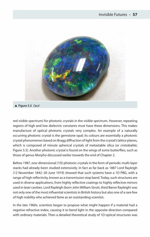
Invisible Futures • 57
red visible spectrum) for photonic crystals in the visible spectrum. However, repeating regions of high and low dielectric constants must have these dimensions. This makes manufacture of optical photonic crystals very complex. An example of a naturally occurring photonic crystal is the gemstone opal; its colours are essentially a photonic crystal phenomenon based on Bragg diff raction of light from the crystal’s lattice planes, which is composed of minute spherical crystals of metastable silica (or cristobalit e; Figure 3.3). Another photonic crystal is found on the wings of some butterfl ies, such as those of genus Morpho discussed earlier towards the end of Chapter 2.
Before 1987, one-dimensional (1D) photonic crystals in the form of periodic multi-layer stacks had already been studied extensively. In fact as far back as 1887 Lord Rayleigh (12 November 1842–30 June 1919) showed that such systems have a 1D PBG, with a range of high refl ectivity, known as a transmission stop band. Today, such structures are used in diverse applications, from highly refl ective coatings to highly refl ective mirrors used in laser cavities. Lord Rayleigh (born John William Strutt, third Baron Rayleigh) was not only one of the most infl uential scientists in British history but also one of a rare few of high nobility who achieved fame as an outstanding scientist.
In the late 1960s, scientists began to propose what might happen if a material had a negative refractive index, causing it to bend light in the opposite direction compared with ordinary materials. Then a detailed theoretical study of 1D optical structures was
Figure 3.3 Opal
58 • Stealth Warship
performed by Bykov in the early 1970s [3], who speculated as to what could happen if two-dimensional (2D) or three-dimensional (3D) periodic optical structures were used, although at this time beyond current technical fabrication capabilities. However, practical demonstration of 2D and 3D structures also had to wait until the publication of two key academic papers in 1987 by Eli Yablonovitch and John Sajeey on photonic crystals [4, 5]. Both papers concerned high-dimensional periodic optical structures or photonic crystals.
Because of the diffi culty of fabricating these structures at optical scales, as already mentioned, early studies were made in the microwave regime, where photonics structures can be built on more accessible centimetre scales, because of a useful property of EM fi elds known as scale invariance – solutions to Maxwell’s equations which have no natural length scale and solutions such that centimetre-sized structures at microwave frequencies are the same as those for nanometre-sized structures at optical frequencies. For example, if the ratio size of the structure (d) to the wavelength (λ) is given as d/λ, then for a 3 cm structure at a wavelength of 6 cm the ratio of 0.5 is the same as that for a 300 nm structure examined at a wavelength of 600 nm (red wavelength).
In 1991, Yablonovitch demonstrated the fi rst 3D PBG in the microwave regime [6]. In 1996, Thomas Krauss made the fi rst demonstration of a 2D photonic crystal at optical wavelengths [7]. Although such techniques are still to mature into widespread commercial applications, 2D photonic crystals have found commercial use in photonic crystal fi bres (known as holey fi bres because of the air holes that run through them). Photonic crystal fi bres were fi rst developed by my colleague Philip St John Russell in 1998 [8] at the Optoelectronic Research Centre (ORC), Southampton, with whom Sergio Barcelos and I worked on optical fi bre surface plasmon resonance (SPR) sensors [9, 10]. Holey fi bres can be designed to possess enhanced properties over (normal) optical fi bres, such as reduced dispersion (spreading) of laser pulses in the fi bre.
Development of 3D photonic crystals is slow, as there are no readily applicable existing techniques from the semiconductor industry for 3D PBG materials. Another strand of research that has been trying to construct 3D photonic structures is that of self-assembly – essentially allowing mixtures of dielectric nanospheres to settle out of complex colloidal solutions or even liquid crystal phases.
Smith’s fi rst microwave metamaterial was composed of peculiar periodic patterns of rings and wires on a former background of fi bre glass. Metamaterials have a negative refractive index, bending light towards the normal, so that at centimetric wavelengths microwaves incident on the cloak bend around it, so an observer ‘sees’ waves pass as it were through empty space.

Invisible Futures • 59
Almost all materials in optics, such as water or glass, have positive values for both electrical permittivity and magnetic permeability. However, some metals (such as silver, gold and aluminium) have negative permittivity at visible wavelengths. A material having either, but not both, permittivity or permeability negative is opaque to EM radiation, so appearing highly refl ective (metallic) and often coloured. The refractive index of materials is given by N = ±√(ε × μ). All transparent materials have positive values for both ε and μ. However, for man-made engineered metamaterials with ε < 0 and μ < 0, this will still produce a real positive N value. The consequences of this are quite profound; for example, if we just consider Snell’s law, that is, N
1 sin θ
1 = N
2 sin θ
2
and if N2 is negative, light rays will be refracted on the same side of the normal on
entering the material!
Optical Metamaterials
Engineers at Purdue University were the fi rst researchers to create a material that has a ‘negative index of refraction’ in the near infra-red (NIR) wavelengths of light that are used for telecommunications, a step that should lead in future to better and faster communications and imaging technologies. ‘This work represents a milestone because it demonstrates that it is possible to have a negative refractive index in the optical range, which increases the likelihood of harnessing this phenomenon for optics and communications’, said Vladimir Shalaev, the Robert and Anne Burnett Professor of Electrical and Computer Engineering. The material consists of tiny parallel ‘nanorods’ of gold that conduct clouds of electrons called ‘plasmons’ with frequencies of EM radiation in the NIR part of the EM spectrum. The wavelength size of this NIR light is very close to 1.5 μm (1.5 millionth of a metre), the same wavelength used for current generations of broadband fi bre-optic communications. ‘This is the most important wavelength for communications’, relates Shalaev.
The exciting thing about these newly engineered nanorods is that they are able to reverse the process of refraction, which occurs as EM waves bend when passing from one material to another and is caused by a change in the speed of light propagation. Scientists measure the bending of radiation by its ‘index of refraction’. Refraction causes the bent-stick-in-water eff ect, when a stick placed in a glass of water appears bent when viewed from outside. Each material has its own refractive index, the N described earlier, which predicts how much light bends in that material and how much the speed of light slows down while passing through it. All natural materials, such as glass, air and water, have positive refractive indices. For example, if the index of refraction is defi ned
60 • Stealth Warship
as N = c/v, where c is the speed of light in vacuum and v the speed the light travels in a particular medium, we can assign various refractive index values to diff erent media. Consider light travelling in vacuum; then clearly N = c/c = 1 and the refractive index of vacuum is 1. In air, where light travels a little less than the speed of light in vacuum, the refractive index will be a little greater than 1. For light travelling in water, where the speed v is about (3/4)c, N = c/(3/4)c = 4/3 or 1.333 approximately. More about basic wave properties, such as refraction and refl ection, are covered from the view point of the marine engineer elsewhere [11].
In 2000, Sir John Pendry at Imperial College London theorised that slabs of such material might create a ‘superlens’ that would improve the quality of medical imaging technologies [12]. In theory, such metamaterial lenses could compensate for the loss of light that inevitably occurs as an image passes through a lens or compound (multiple) lens system. Lenses and imaging systems could be substantially improved if this lost light (or evanescent light) were ‘recovered’. An imaging system with a combination of normal positive refraction and negative refraction could potentially restore the lenses’ imaging ability. The fi rst real superlens having a negative refractive index provided a resolution three times better than the theoretical diff raction limit and was demonstrated at the University of Toronto by A Grbic and GV Eleftheriades in 2006 [13].
Various research groups have now successfully fabricated ‘metamaterials’ of tiny metal rings and rods, all having a negative refraction index. Purdue researchers created the fi rst metamaterial with a negative refractive index in the NIR [14], just beyond visible light, demonstrating the feasibility of applying the concept to communications in the fi rst instance but opening the possibility for future sensing and stealth applications and visible light operation (Figure 3.4).
The material, created by Purdue engineers, conducts clouds of electrons or ‘plasmons’ with a frequency of light in the NIR, the same wavelength used for fi bre-optic communications. Each rod is about as wide as 100 nm and 700 nm long.
‘The challenge was to fabricate a structure that would have not only an electrical response, but also a magnetic response in the NIR range’, Shalaev said. Gold nanorods conduct plasmons, moving as if they were a single coordinated object instead of many millions of individual separate electrons. Light from a laser shone onto the nanorods induces an ‘electro-optical current’ in the tiny circuit. Each rod is only about 100 nm wide and 700 nm long. ‘These rods basically conduct current because they are a metal, producing an effect we call optical inductance, while a material between the rods produces another effect called optical capacitance’, Shalaev said.
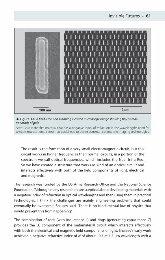
Invisible Futures • 61
The result is the formation of a very small electromagnetic circuit, but this circuit works in higher frequencies than normal circuits, in a portion of the spectrum we call optical frequencies, which includes the Near Infra Red. So we have created a structure that works as kind of an optical circuit and interacts eff ectively with both of the fi eld components of light: electrical and magnetic.
The research was funded by the US Army Research Offi ce and the National Science Foundation. ‘Although many researchers are sceptical about developing materials with a negative index of refraction in optical wavelengths and then using them in practical technologies, I think the challenges are mainly engineering problems that could eventually be overcome’, Shalaev said. ‘There is no fundamental law of physics that would prevent this from happening.’
The combination of rods (with inductance L) and rings (generating capacitance C) provides the LC component of the metamaterial circuit which interacts eff ectively with both the electrical and magnetic fi eld components of light. Shalaev’s early work achieved a negative refractive index of N of about –0.3 at 1.5 μm wavelength with a
Figure 3.4 A fi eld-emission scanning electron microscope image showing tiny parallel nanorods of gold
Note: Gold is the fi rst material that has a ‘negative index of refraction’ in the wavelengths used for telecommunications, a step that could lead to better communications and imaging technologies.
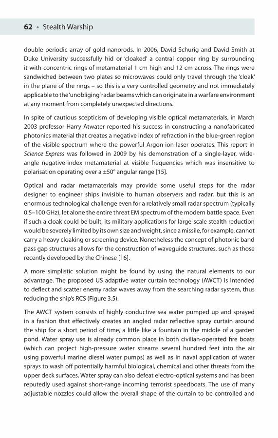
62 • Stealth Warship
double periodic array of gold nanorods. In 2006, David Schurig and David Smith at Duke University successfully hid or ‘cloaked’ a central copper ring by surrounding it with concentric rings of metamaterial 1 cm high and 12 cm across. The rings were sandwiched between two plates so microwaves could only travel through the ‘cloak’ in the plane of the rings – so this is a very controlled geometry and not immediately applicable to the ‘unobliging’ radar beams which can originate in a warfare environment at any moment from completely unexpected directions.
In spite of cautious scepticism of developing visible optical metamaterials, in March 2003 professor Harry Atwater reported his success in constructing a nanofabricated photonics material that creates a negative index of refraction in the blue-green region of the visible spectrum where the powerful Argon-ion laser operates. This report in Science Express was followed in 2009 by his demonstration of a single-layer, wide-angle negative-index metamaterial at visible frequencies which was insensitive to polarisation operating over a ±50° angular range [15].
Optical and radar metamaterials may provide some useful steps for the radar designer to engineer ships invisible to human observers and radar, but this is an enormous technological challenge even for a relatively small radar spectrum (typically 0.5–100 GHz), let alone the entire threat EM spectrum of the modern battle space. Even if such a cloak could be built, its military applications for large-scale stealth reduction would be severely limited by its own size and weight, since a missile, for example, cannot carry a heavy cloaking or screening device. Nonetheless the concept of photonic band pass gap structures allows for the construction of waveguide structures, such as those recently developed by the Chinese [16].
A more simplistic solution might be found by using the natural elements to our advantage. The proposed US adaptive water curtain technology (AWCT) is intended to defl ect and scatter enemy radar waves away from the searching radar system, thus reducing the ship’s RCS (Figure 3.5).
The AWCT system consists of highly conductive sea water pumped up and sprayed in a fashion that eff ectively creates an angled radar refl ective spray curtain around the ship for a short period of time, a little like a fountain in the middle of a garden pond. Water spray use is already common place in both civilian-operated fi re boats (which can project high-pressure water streams several hundred feet into the air using powerful marine diesel water pumps) as well as in naval application of water sprays to wash off potentially harmful biological, chemical and other threats from the upper deck surfaces. Water spray can also defeat electro-optical systems and has been reputedly used against short-range incoming terrorist speedboats. The use of many adjustable nozzles could allow the overall shape of the curtain to be controlled and
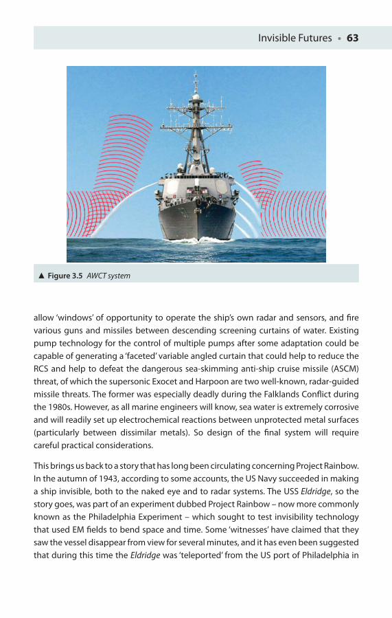
Invisible Futures • 63
allow ‘windows’ of opportunity to operate the ship’s own radar and sensors, and fi re various guns and missiles between descending screening curtains of water. Existing pump technology for the control of multiple pumps after some adaptation could be capable of generating a ‘faceted’ variable angled curtain that could help to reduce the RCS and help to defeat the dangerous sea-skimming anti-ship cruise missile (ASCM) threat, of which the supersonic Exocet and Harpoon are two well-known, radar-guided missile threats. The former was especially deadly during the Falklands Confl ict during the 1980s. However, as all marine engineers will know, sea water is extremely corrosive and will readily set up electrochemical reactions between unprotected metal surfaces (particularly between dissimilar metals). So design of the fi nal system will require careful practical considerations.
This brings us back to a story that has long been circulating concerning Project Rainbow. In the autumn of 1943, according to some accounts, the US Navy succeeded in making a ship invisible, both to the naked eye and to radar systems. The USS Eldridge, so the story goes, was part of an experiment dubbed Project Rainbow – now more commonly known as the Philadelphia Experiment – which sought to test invisibility technology that used EM fi elds to bend space and time. Some ‘witnesses’ have claimed that they saw the vessel disappear from view for several minutes, and it has even been suggested that during this time the Eldridge was ‘teleported’ from the US port of Philadelphia in
Figure 3.5 AWCT system
64 • Stealth Warship
Pennsylvania to Norfolk in Virginia, some hundred miles down the coast. This story is now recognised as being a hoax, with offi cial Navy records placing the USS Eldridge nowhere near Philadelphia during that part of 1943. The Philadelphia Experiment may have turned out to be a hoax, but real developments in stealth technologies are proving to be just as interesting. Ironically the US Navy recently announced its new high-temperature superconductor degaussing facility to be based in Philadelphia. An example of truth being stranger than fi ction!?
Chapter Refl ections
1. It is desired to create a photonic crystal using the phenomenon of diff raction. What should be the desired periodicity of the crystal structure if the wavelength is intended to be 632.8 nm (three signifi cant fi gures)?
2. If the periodicity for a photonic crystal is 200 nm, what is the intended wavelength (one signifi cant fi gure)?
3. For a wavelength λ, what should the periodicity of the complete metamaterial structure be if it repeats 10 times over one wavelength spacing?
4. A diff raction grating of 9,000 lines per centimetre is used with white light.
(a) How many orders of spectra will be seen for the nth-order diff raction d sin θ = nλ?
(b) If the white light is now replaced by a helium-neon (He-Ne) laser operating at 632.8 nm, at what angle will the fi rst-order diff raction maximum be observed if the spacing d is now reduced to 1,800 lines per centimetre (two decimal places)?

Invisible Futures • 65
References
1. Rahm, M, Schurig, D, Roberts, DA, Cummer, SA, Smith DR and Pendry, JB (2008), ‘Design of electromagnetic cloaks and concentrators using form-invariant coordinate transformations of Maxwell’s equations’, Photonics and Nanostructures – Fundamentals and Applications, 6(1): 87–95.
2. Lavers, CR (ed.) (2008), Reeds Volume 6: Basic Electrotechnology for Marine Engineers. London: Adlard Coles Nautical.
3. Bykov, VP (1972), ‘Spontaneous emission in a periodic structure’, Soviet Journal of Experimental and Theoretical Physics, 35(2): 269–273.
4. Yablonovitch, E (1987), ‘Inhibited spontaneous emission in solid-state physics and electronics’, Physical Review Letters, 58(20): 2059–2062.
5. John, S (1987), ‘Strong localization of photons in certain disordered dielectric superlattices’, Physical Review Letters, 58(23): 2486–2489.
6. Yablonovitch, E, Gmitter, TJ and Leung, KM (1991), ‘Photonic band structure: The face-centered-cubic case employing nonspherical atoms’, Physical Review Letters, 67(17): 2295–2298.
7. Krauss, TF, DeLaRue, RM and Brand, S (1996), ‘Two-dimensional photonic-bandgap structures operating at near-infrared wavelengths’, Nature, 383(6602): 699–702.
8. Russell, P St J (2003), ‘Photonic crystal fi bers’, Science, 299: 358–362. (Review article.)
9. Barcelos, S, Lavers, CR, Zervas, M and Russell, P St J (1993), Mode-selective fi bre coupling using long range surface-plasmons, LEOS Annual Meeting, pp 177–178, 15th–19th November, San Jose, CA.
10. Lavers, CR, Mosedale, S, Itoh, K, Wu, S, Murabayashi, M, Mauchline, I, Stewart, G, Ross, I, Shafi r, E and Qi, Z (2004), ‘Planar optical waveguides for potential military and clinical sensing applications’, Journal of Defence Science, 9(2):69–81.
11. Lavers, CR (2011), Basic Electromagnetic Wave Concepts for Engineers. Rayleigh, NC: Lulu Enterprises, Inc.
12. Pendry, JB (2000), ‘Negative refraction makes a perfect lens’, Physical Review Letters (American Physical Society), 85: 3966.
13. Grbic, A and Eleftheriades, GV (2004), ‘Overcoming the diff raction limit with a planar left-handed transmission-line lens’, Physical Review Letters, 92(11): 117403.
14. http://web.ics.purdue.edu/.
15. Burgos, SP, de Waele, R, Polman, A and Atwater, HA (2010), ‘A single-layer wide-angle negative-index metamaterial at visible frequencies’, Nature Materials, 9: 407–412.
16. Huang, Y, Feng, Y and Jiang, T (2007), ‘Electromagnetic cloaking by layered structure of homogeneous isotropic materials’, Optics Express, 15: 11133–11141.
4INFRA-RED
All warfare is based on deception.
Sun Tzu, translated from The Art of War (c. 5th century BC)
Infra-red Heat Reduction
At the height of the Cold War during the 1970s the emphasis of stealth and detection shifted once more with the deployment of a new generation of missiles that could passively home in on to the very hottest areas of a target by detecting and tracking the infra-red heat radiation given off . The US Navy had tried – and failed – to develop heat-seeking devices during the Second World War (one such project was Polaroid’s Project Dove), and it was not until the Vietnam War that they became common place. The US Air Force (USAF) fi rst acquired its heat-seeking AIM-4 Falcon and then the more widely recognised AIM-9 Sidewinder.
The Hughes AIM-4 Falcon was the fi rst operational guided air-to-air missile to enter service with the USAF, and the development of this guided air-to-air missile began in the mid-1940s. Hughes aircraft was initially awarded a subsonic missile contract which was superseded by a supersonic requirement in 1947. The original purpose was for a self-defence weapon capability on bomber aircraft, but from 1950 it was decided that it should be used on fi ghter aircraft instead, especially in an interception role. The Sidewinder meanwhile was named after the heat-sensing ability of the pit viper (Figure 4.1).
The AIM-9 Sidewinder is a heat-seeking, short-range, air-to-air missile carried by several modern fi ghter aircraft and more recently by modifi ed gunship helicopters. The missile entered service with the US Navy fairly early on in the mid-1950s, and various variants

Infra-red • 67
and upgrades remain in active service with many air forces worldwide after fi ve decades of active service, testifying to its relevant potency today. The USAF also purchased the Sidewinder after the missile had been developed by the US Navy, and it is perhaps with the Air Force that it is more usually associated through the medium of fi lm.
The Sidewinder is the most widely used missile of all time in the military of the West, with over 100,000 missiles produced for the United States and for over 25 other nations, of which approximately 1% have actually been used under live combat conditions. The AIM-9 is one of the oldest (and consequently least expensive) and successful air-to-air missiles to date. Not a bad record for a missile that was originally designed to be a straightforward platform upgrade. It has been reported that the design goals for the original Sidewinder were to produce a reliable and eff ective missile with the ‘electronic complexity of a … radio and the mechanical complexity of a washing machine’ – goals which were well accomplished in these early missiles!
Current versions of the AIM-9 (the Mach 2 AIM9-L Super Sidewinder weighs a modest 85 kg with an 11.4 kg fragmentation warhead) are improved on their original design, although these are currently being replaced by the advanced short-range air-to-air
Figure 4.1 US Marine Corps Lance Cpl Leander Pickens arms an AIM-9 Sidewinder missile on a FA-18C Hornet

68 • Stealth Warship
missiles (ASRAAM), with higher reliability from having solid state electronics which can enable guidance to be ‘smarter’ at discriminating targets from clutter and with greater resistance to jamming. Nonetheless, both of these missiles are extremely potent and provide a very strong case for the continued use of fl are decoys as well as for the development of various laser-based countermeasure systems, such as Nemesis, which are being introduced.
Heat-seeking missiles typically use a detector made from a semiconductor such as lead sulphide, in which incident heat, or infra-red photons, change the resistivity of a semiconductor material.
Such heat-seeking missile technology is generally bad news for naval warfare, as warships once at sea emit signifi cant amounts of heat, so reducing their ‘carbon footprint’ is essential for several reasons. Ships radiate or lose heat from their exhaust plume, funnels, vents, open hatches, recently fi red guns, recently embarked helicopters and other features. These platform emissions are radiated into the environment, and by virtue of the atmosphere’s transparency these heat wavelengths may be detected over very great distances. Add to this fact the problem that thermal heat sensor systems operate passively (they do not transmit heat or any other radiated signal themselves), and thus unlike active radar provide very little warning, if at all, of imminent attack without the use of sophisticated warning receivers.
Ships, however, are easily detected as warm platforms against cold seas and skies, which enable enemy sensors to detect or guide missiles to intercept with relative ease. Unlike vehicles and troops on land, there is no simple cover at sea, and no use is to be made of diff erent natural materials.
Fortunately current generations of heat-seeking missiles are non-imaging, in that they do not ‘see’ the world around us with clear images. A heat seeker will detect an intense ‘blob’ of heat and will target this; thus it is relatively easy to defeat a heat-seeking missile with a more attractive ‘hot’ source of heat – if there is enough time to deploy the decoy source. Heat-seeker missiles will target the middle infra-red (MIR) band of the electromagnetic spectrum in the range between 3 and 5 μm, that is, 3 to 5 millionth of a metre, whilst true thermal imagers watch and scrutinise in the range of 8–14 μm, somewhat further in wavelength with reduced scattering when compared with the MIR band, although the atmosphere is overall less absorbing in the MIR.
However, recent developments in materials and system design will soon provide a new generation of 3–5 μm imagers which will render current heat-seeking countermeasures less eff ective unless signifi cant improvements are made. The middle band threat is currently combated by taking practical methods to reduce the heat from the operation of diesel and gas turbine engines (200–500°C).
Infra-red • 69
Infra-red emission can generally be divided into two parts: the so-called infra-red cross section (IRCS), which is the total emitted power from a target, and the infra-red signature (IRS), which is the target’s detailed distribution of heat emitters. If a ship’s IRCS is suffi ciently reduced, it will enhance the overall eff ectiveness of the ship’s decoys, such as the use of pyrotechnic phosphorous fl ares or those of magnesium/aluminium design. Such a fl are not only produces a bright white fl ash to the human observer, which may last for several tens of seconds, but also produces copious amounts of heat, tricking the heat-seeking missile into thinking it has acquired a real, hot ship target.
Imaging sensors, however, can see both the IRCS (the intense bright signal) as well as the ship’s detail (its signature), allowing for the possibility of actual image and target (platform) identifi cation. To avoid identifi cation, it is thus vital to reduce both the IRCS and to ‘blur’ the signature.
Passive ship heat detection depends on several important factors, such as the level of energy actually emitted towards an infra-red detector and on the propagation conditions, conditions which can change extremely quickly in a maritime environment. Infra-red band absorption by atmospheric molecules is also highly wavelength-dependent because of the vibrations of common molecules with three atoms such as water and carbon dioxide. Light sand combined with sea salt spray also provide further additional factors.
As stated previously, warm ships are relatively easy to detect against a cold sea and an even colder sky background, so warm ships will be easier to detect in the Arctic and Antarctic waters rather than in the relatively warm seas of the Caribbean, for example. However, a ship may also be detected as its air-cooled ship’s plating can on occasion appear much colder than its background. This phenomenon arises as follows. Cold sky refl ections (with clouds typically at temperatures between −30 and −40°C) can be refl ected from a ship’s metal surfaces if improperly angled (metal surfaces are still good refl ectors at these thermal wavelengths) and will then be in danger of ‘showing up’ with a strong contrast diff erence. Of course, appropriate tilting of the superstructure can help take this risk into account, but the reader must be reminded that any change of tilt must not compromise the superstructure tilt that has already been introduced to reduce the probability of radar detection.
In the 3–5 μm band (or so-called short-wave region of the electromagnetic spectrum), various hot objects include propulsion units’ exhaust plumes, uptake and funnel surfaces. This band has a relatively high contrast but generally poor edge defi nition, like a bright light source against a poorly lit background, something which is easy to detect on a dark night, but it is not easy to identify actually what the light source is. Is the source a man with a torch or a vehicle approaching with one defective light?
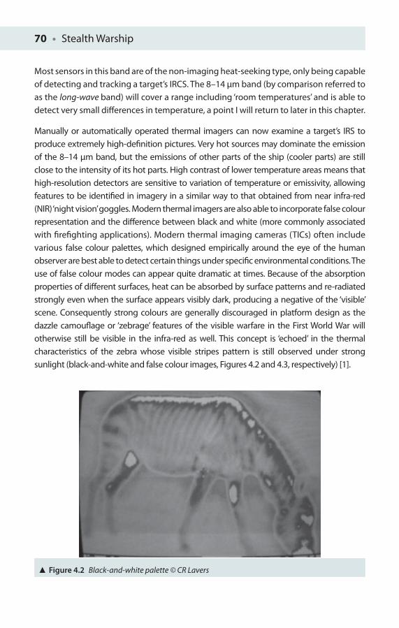
70 • Stealth Warship
Most sensors in this band are of the non-imaging heat-seeking type, only being capable of detecting and tracking a target’s IRCS. The 8–14 μm band (by comparison referred to as the long-wave band) will cover a range including ‘room temperatures’ and is able to detect very small diff erences in temperature, a point I will return to later in this chapter.
Manually or automatically operated thermal imagers can now examine a target’s IRS to produce extremely high-defi nition pictures. Very hot sources may dominate the emission of the 8–14 μm band, but the emissions of other parts of the ship (cooler parts) are still close to the intensity of its hot parts. High contrast of lower temperature areas means that high-resolution detectors are sensitive to variation of temperature or emissivity, allowing features to be identifi ed in imagery in a similar way to that obtained from near infra-red (NIR) ‘night vision’ goggles. Modern thermal imagers are also able to incorporate false colour representation and the diff erence between black and white (more commonly associated with fi refi ghting applications). Modern thermal imaging cameras (TICs) often include various false colour palettes, which designed empirically around the eye of the human observer are best able to detect certain things under specifi c environmental conditions. The use of false colour modes can appear quite dramatic at times. Because of the absorption properties of diff erent surfaces, heat can be absorbed by surface patterns and re-radiated strongly even when the surface appears visibly dark, producing a negative of the ‘visible’ scene. Consequently strong colours are generally discouraged in platform design as the dazzle camoufl age or ‘zebrage’ features of the visible warfare in the First World War will otherwise still be visible in the infra-red as well. This concept is ‘echoed’ in the thermal characteristics of the zebra whose visible stripes pattern is still observed under strong sunlight (black-and-white and false colour images, Figures 4.2 and 4.3, respectively) [1].
Figure 4.2 Black-and-white palette © CR Lavers

Infra-red • 71
Diff erent display modes are used to help reveal specifi c target features and usually involve diff erent digital signal-processing computer software algorithms to maximise detectability. Digital data may also be exported via a data link from a camera, maximising the availability of information for other users.
IRCS Contributors
Gas turbine exhaust plumes are the biggest IRCS contributor usually operating between 300°C and 500°C at full power. Gas turbines provide power to drive a ship’s main propulsion shaft. Energy is added to the gas stream in the combustor, where fuel is mixed with air and ignited. In the combustor’s high-pressure environment, fuel combustion will increase the gases’ temperature. These combustion products are then forced into the turbine section. In the turbine, the relatively high velocity and volume of heated gas fl ow is directed over the turbine’s blades, spinning the turbine which in turn powers the compressor.
These exhaust gases then leave the ship’s funnel forming a vertical plume, which as it expands begins to cool in temperature. Plume shapes and temperatures will tend to vary with the diff erent engines and operating conditions, with diff erent operating platforms having relatively well-defi ned visible plume characteristics. These optical
Figure 4.3 False colour palette © CR Lavers
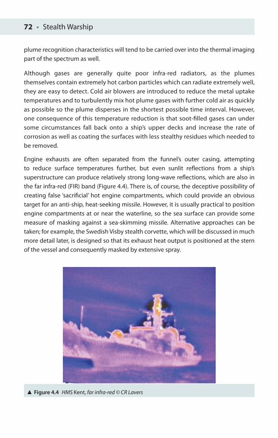
72 • Stealth Warship
plume recognition characteristics will tend to be carried over into the thermal imaging part of the spectrum as well.
Although gases are generally quite poor infra-red radiators, as the plumes themselves contain extremely hot carbon particles which can radiate extremely well, they are easy to detect. Cold air blowers are introduced to reduce the metal uptake temperatures and to turbulently mix hot plume gases with further cold air as quickly as possible so the plume disperses in the shortest possible time interval. However, one consequence of this temperature reduction is that soot-fi lled gases can under some circumstances fall back onto a ship’s upper decks and increase the rate of corrosion as well as coating the surfaces with less stealthy residues which needed to be removed.
Engine exhausts are often separated from the funnel’s outer casing, attempting to reduce surface temperatures further, but even sunlit refl ections from a ship’s superstructure can produce relatively strong long-wave refl ections, which are also in the far infra-red (FIR) band (Figure 4.4). There is, of course, the deceptive possibility of creating false ‘sacrifi cial’ hot engine compartments, which could provide an obvious target for an anti-ship, heat-seeking missile. However, it is usually practical to position engine compartments at or near the waterline, so the sea surface can provide some measure of masking against a sea-skimming missile. Alternative approaches can be taken; for example, the Swedish Visby stealth corvette, which will be discussed in much more detail later, is designed so that its exhaust heat output is positioned at the stern of the vessel and consequently masked by extensive spray.
Figure 4.4 HMS Kent, far infra-red © CR Lavers

Infra-red • 73
Exhaust ducts are unfortunately very good high-temperature radiators, so most ducts are positioned vertically so that they are only visible to high-fl ying aircraft or in recent years potentially from satellites as well. At low look angles, however, those usually associated with surfaced submarines, patrolling ships and most missiles, vertical ducts are almost invisible. Some auxiliary exhaust ducts are horizontal under rare circumstances, and it is usual to place screen baffl es in front of them in this case.
A recently embarked helicopter or missile blast screens just after fi ring are also likely to produce transient emissions which may betray a ship’s presence, so placing a helicopter inside its hanger and closing the hanger door as soon as possible are good precautionary measures to take. It should not be forgotten that a vehicle, aircraft or ship may still be detectable with thermal sensors many hours after the engine has been switched off !
As IRCS is mainly used by heat seekers in the 3–5 μm band, most techniques historically have been aimed with the focused intent to reduce radiation from very hot objects, such as a diesel engine exhaust, as most of the heat radiated will be associated with these hot sources.
In summary, at this point, oddly shaped air blowers can reduce funnel temperatures and mix exhaust gases with cold air. Equally hot compartments may be insulated from direct thermal contact with the hull, whilst high-temperature ducts point up, making them hard to see from the normal viewing direction.
As infra-red emission is a surface problem principally, coating ships in low heat emitting or low-emissivity paint is a vital requirement as it will reduce the IRCS signifi cantly. Painted objects will frequently behave much like black bodies in terms of their infra-red emission. Emissivity can be as high as 99% effi cient or ε = 0.99 (1 being the maximum value for matt paint), whilst normal oil paints are also rather good infra-red emitters, so tailored designer spray-on low-emissivity paints have been developed for modern naval use and other temperature-sensitive applications, whilst at the same time incorporating radar absorbent particles to minimise the radar cross section (RCS) and having the appropriate visual colour to combat visible detection! In this way, emissivity can be reduced from typical oil paint values of 0.92–0.94 to provide an approximately sixfold reduction in emissivity, for example, about 0.15–0.17. Emissivity is also highly relevant to the consideration of refl ected sunlight and infra-red, as recent sources in the public domain suggest that conventional paints refl ect about 60% of the heat incident on them, though newer low infra-red ‘greys’ (as found on USN F-14 and F-18) can refl ect as little as 5% to 15% of the radiation incident upon them. It is known that a well-polished aircraft canopy may refl ect enough energy for a lock-on in the thermal band to be achieved, as well as providing
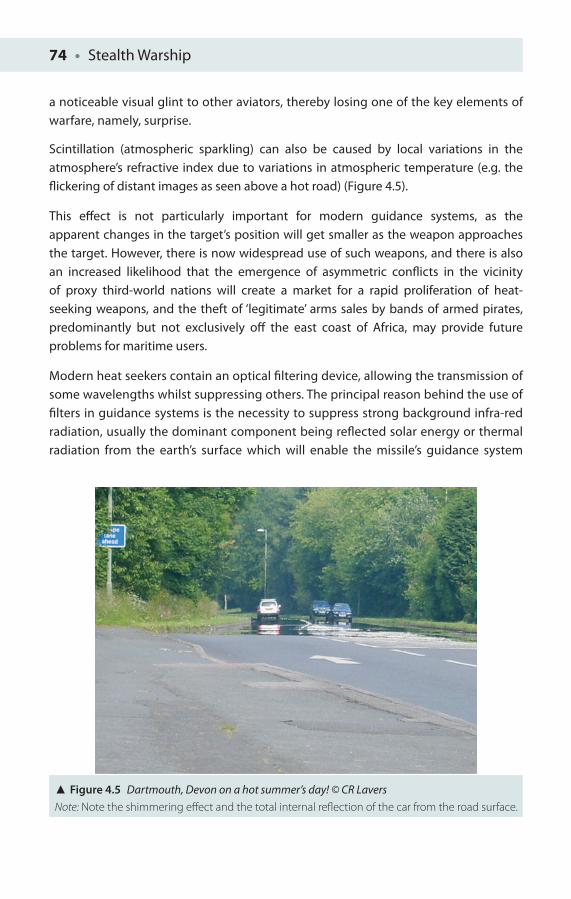
74 • Stealth Warship
a noticeable visual glint to other aviators, thereby losing one of the key elements of warfare, namely, surprise.
Scintillation (atmospheric sparkling) can also be caused by local variations in the atmosphere’s refractive index due to variations in atmospheric temperature (e.g. the fl ickering of distant images as seen above a hot road) (Figure 4.5).
This eff ect is not particularly important for modern guidance systems, as the apparent changes in the target’s position will get smaller as the weapon approaches the target. However, there is now widespread use of such weapons, and there is also an increased likelihood that the emergence of asymmetric confl icts in the vicinity of proxy third-world nations will create a market for a rapid proliferation of heat-seeking weapons, and the theft of ‘legitimate’ arms sales by bands of armed pirates, predominantly but not exclusively off the east coast of Africa, may provide future problems for maritime users.
Modern heat seekers contain an optical fi ltering device, allowing the transmission of some wavelengths whilst suppressing others. The principal reason behind the use of fi lters in guidance systems is the necessity to suppress strong background infra-red radiation, usually the dominant component being refl ected solar energy or thermal radiation from the earth’s surface which will enable the missile’s guidance system
Figure 4.5 Dartmouth, Devon on a hot summer’s day! © CR LaversNote: Note the shimmering eff ect and the total internal refl ection of the car from the road surface.
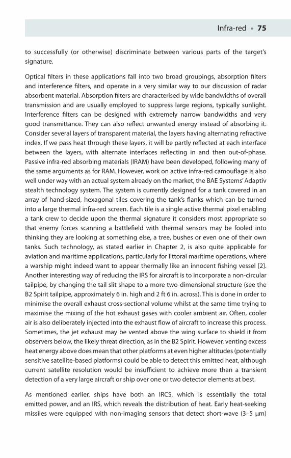
Infra-red • 75
to successfully (or otherwise) discriminate between various parts of the target’s signature.
Optical fi lters in these applications fall into two broad groupings, absorption fi lters and interference fi lters, and operate in a very similar way to our discussion of radar absorbent material. Absorption fi lters are characterised by wide bandwidths of overall transmission and are usually employed to suppress large regions, typically sunlight. Interference fi lters can be designed with extremely narrow bandwidths and very good transmittance. They can also refl ect unwanted energy instead of absorbing it. Consider several layers of transparent material, the layers having alternating refractive index. If we pass heat through these layers, it will be partly refl ected at each interface between the layers, with alternate interfaces refl ecting in and then out-of-phase. Passive infra-red absorbing materials (IRAM) have been developed, following many of the same arguments as for RAM. However, work on active infra-red camoufl age is also well under way with an actual system already on the market, the BAE Systems’ Adaptiv stealth technology system. The system is currently designed for a tank covered in an array of hand-sized, hexagonal tiles covering the tank’s fl anks which can be turned into a large thermal infra-red screen. Each tile is a single active thermal pixel enabling a tank crew to decide upon the thermal signature it considers most appropriate so that enemy forces scanning a battlefi eld with thermal sensors may be fooled into thinking they are looking at something else, a tree, bushes or even one of their own tanks. Such technology, as stated earlier in Chapter 2, is also quite applicable for aviation and maritime applications, particularly for littoral maritime operations, where a warship might indeed want to appear thermally like an innocent fi shing vessel [2].Another interesting way of reducing the IRS for aircraft is to incorporate a non-circular tailpipe, by changing the tail slit shape to a more two-dimensional structure (see the B2 Spirit tailpipe, approximately 6 in. high and 2 ft 6 in. across). This is done in order to minimise the overall exhaust cross-sectional volume whilst at the same time trying to maximise the mixing of the hot exhaust gases with cooler ambient air. Often, cooler air is also deliberately injected into the exhaust fl ow of aircraft to increase this process. Sometimes, the jet exhaust may be vented above the wing surface to shield it from observers below, the likely threat direction, as in the B2 Spirit. However, venting excess heat energy above does mean that other platforms at even higher altitudes (potentially sensitive satellite-based platforms) could be able to detect this emitted heat, although current satellite resolution would be insuffi cient to achieve more than a transient detection of a very large aircraft or ship over one or two detector elements at best.
As mentioned earlier, ships have both an IRCS, which is essentially the total emitted power, and an IRS, which reveals the distribution of heat. Early heat-seeking missiles were equipped with non-imaging sensors that detect short-wave (3–5 μm)
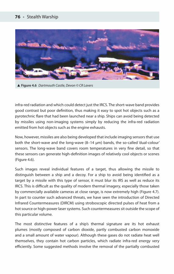
76 • Stealth Warship
infra-red radiation and which could detect just the IRCS. The short-wave band provides good contrast but poor defi nition, thus making it easy to spot hot objects such as a pyrotechnic fl are that had been launched near a ship. Ships can avoid being detected by missiles using non-imaging systems simply by reducing the infra-red radiation emitted from hot objects such as the engine exhausts.
Now, however, missiles are also being developed that include imaging sensors that use both the short-wave and the long-wave (8–14 μm) bands, the so-called ‘dual-colour’ sensors. The long-wave band covers room temperatures in very fi ne detail, so that these sensors can generate high-defi nition images of relatively cool objects or scenes (Figure 4.6).
Such images reveal individual features of a target, thus allowing the missile to distinguish between a ship and a decoy. For a ship to avoid being identifi ed as a target by a missile with this type of sensor, it must blur its IRS as well as reduce its IRCS. This is diffi cult as the quality of modern thermal imagery, especially those taken by commercially available cameras at close range, is now extremely high (Figure 4.7). In part to counter such advanced threats, we have seen the introduction of Directed Infrared Countermeasures (DIRCM) using stroboscopic directed pulses of heat from a hot source or high-power laser systems. Such countermeasures sit outside the scope of this particular volume.
The most distinctive features of a ship’s thermal signature are its hot exhaust plumes (mostly composed of carbon dioxide, partly combusted carbon monoxide and a small amount of water vapour). Although these gases do not radiate heat well themselves, they contain hot carbon particles, which radiate infra-red energy very effi ciently. Some suggested methods involve the removal of the partially combusted
Figure 4.6 Dartmouth Castle, Devon © CR Lavers
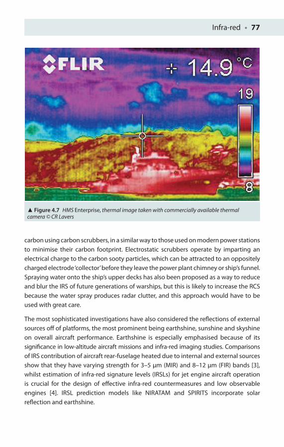
Infra-red • 77
carbon using carbon scrubbers, in a similar way to those used on modern power stations to minimise their carbon footprint. Electrostatic scrubbers operate by imparting an electrical charge to the carbon sooty particles, which can be attracted to an oppositely charged electrode ‘collector’ before they leave the power plant chimney or ship’s funnel. Spraying water onto the ship’s upper decks has also been proposed as a way to reduce and blur the IRS of future generations of warships, but this is likely to increase the RCS because the water spray produces radar clutter, and this approach would have to be used with great care.
The most sophisticated investigations have also considered the refl ections of external sources off of platforms, the most prominent being earthshine, sunshine and skyshine on overall aircraft performance. Earthshine is especially emphasised because of its signifi cance in low-altitude aircraft missions and infra-red imaging studies. Comparisons of IRS contribution of aircraft rear-fuselage heated due to internal and external sources show that they have varying strength for 3–5 μm (MIR) and 8–12 μm (FIR) bands [3], whilst estimation of infra-red signature levels (IRSLs) for jet engine aircraft operation is crucial for the design of eff ective infra-red countermeasures and low observable engines [4]. IRSL prediction models like NIRATAM and SPIRITS incorporate solar refl ection and earthshine.
Figure 4.7 HMS Enterprise, thermal image taken with commercially available thermal camera © CR Lavers

78 • Stealth Warship
The Laws of Infra-red Emission
Infra-red radiation is emitted by all objects above absolute zero; however, the amount emitted, and its wavelength distribution, depend on the body’s absolute temperature T and its emissivity ε. Emissivity is the actual emission from the surface of a body, compared with that from an identical perfect radiating source or ‘black body’, at the same temperature. Consequently, a ‘black body’ will have a maximum emissivity value of one, and a perfect insulator will have an emissivity value of zero. Many objects closely resemble a ‘black body’ in their infra-red emission. For consideration of energy and the relationship between radiated heat and temperature, it is important to use the correct temperature scale. Although centigrade is quite appropriate for most purposes with 100 equal steps between the melting point of ice and the boiling point of water, a blockof ice at 0°C still has a considerable amount of energy. If all the energy within the block of ice could be extracted, the temperature of the ice block would fall considerably. Eventually when all the energy from an object has been extracted, the object will sit at the bottom of the energy scale and correspondingly at the bottom of the temperature scale. This ‘absolute zero’ of temperature is at −273°C approximately, and to convert from degree Celsius to the Kelvin scale (in K and without the degree symbol!) it is necessary to add 273, for example 10°C on the Kelvin scale will be 10 + 273 = 283 K.
There are three important properties of radiating bodies of which a ship’s target will radiate signifi cant amounts of heat:
1. The wavelength (λpeak) at which the peak of emission occurs can be expressed by a relatively simple function of absolute temperature T, and is found using a formulae known as Wien’s displacement law, named after the German physicist Wilhelm Wien (1864–1928):
λpeak = 2,900 _____ T μm
For example, for a hot aircraft exhaust at 800 K, the peak wavelength of emission will be found very close to 3.6 μm, whilst a person at room temperature (with a skin surface temperature of about 27°C) will have a Kelvin temperature of about 300 K and a peak wavelength of emission of 10 μm, right in the middle of t he range of modern TICs used in the FIR to detect missing persons and for surveillance.
This has a huge implication on the correct choice of sensor and infra-red band to monitor. Physicists and engineers will often plot the intensity distribution of
Infra-red • 79
thermal radiation with wavelength to obtain a series of curves or ‘black body’ curves.
2. The radiated intensity I is given by the following equation:
I = εσT 4 Wm−2
where I is the power per unit area in Wm−2, ε is the emissivity, σ is the Stefan–Boltzmann constant (5.67 × 10⁻⁸ W m−2 K−4) and T is the temperature in Kelvin (K = °C + 273), as previously mentioned.
Note of caution: The Stefan–Boltzmann constant uses the same symbol as that already encountered with RCS. They are, however, quite diff erent quantities and should not be confused. Diff erent technical studies often use the same symbols for diff erent quantities.
Consequently, we can establish both the peak emission wavelength and the target intensity. However, in terms of contrast, a ship will be hard to detect if its thermal intensity Iship is the same as the background sea intensity Isea.
Furthermore, if both the emissivity and temperature of a platform can be controlled, this will have an implication on thermal maximum detection range.
3. Small changes in temperature will actually give rise to large changes in overall infra-red emission. This can be demonstrated by considering the equation for intensity given in Point 2 above.
If I = εσT4 Wm−2, then it is clear that the relationship between radiated intensity and thermal temperature is refl ected correctly in the following inequality:
I � T 4
Consequently, IT � T 4.
Now if we increase the temperature of an object by 10%, the same inequality must hold true for the new temperature, where I1.1T is proportional to (1.1T)4.
Now dividing one inequality by the other we arrive at the equation I1.1T /IT = (1.1T)4/T 4, which can be rewritten as I1.1T /IT = (1.1)4/14 = 1.464.
Finally, rearranging, I1.1T = 1.464 IT . This means that a 10% increase in temperature will result in a 46.4% increase in radiated intensity, which is a relatively large increase in intensity for a relatively small increase in temperature!
Clearly the importance of infra-red stealth is never likely to be far from the stealth ship designer’s mind and will always have to be taken into account.
80 • Stealth Warship
1. Consider the contributions of heat on board a ship and how they could be minimised.
2. What are the consequences of incorporating IRCS reduction measures into the warship design on the RCS of a stealth ship?
3. A Visby stealth corvette is visually camoufl aged and moored next to the shore in a fj ord near Gothenburg. The thermal intensities of the corvette and the bank vary signifi cantly as a function of time. A reconnaissance aircraft fi tted with a TIC took infra-red photographs of the Visby and adjacent coastline at dusk (1,615 time t0) with the Visby clearly detectable against the coastline.
For the next few hours, the intensity variations of the corvette and the bank are given by Ifj ord = Ifj ord (t0)e−λ1t
for the fj ord and Iship = Iship (t0)e−λ2t for the ship, where Ifj ord(t0) = 100 W m−2, λ1 = 1.1 hr−1, Iship(t0) = 230 W m−2 and λ2 = 4.2 hr−1.
Examination of photographs taken at a diff erent time showed that the ship could not be discerned from the fj ord. Question: At what time will this occur (nearest minute)?
4. During an Atlantic storm, a man has fallen overboard from a ship. He initially has a surface temperature of 23°C. Find the following:
(a) His initial peak emission wavelength (two signifi cant fi gures).
(b) The man’s total radiated intensity; his emissivity is 0.93 (one decimal place); σ = 5.67 × 10⁻⁸ W m−2 K−4.
(c) After a period of time, the man’s intensity falls so that he is no longer distinguishable against the sea (sea surface has an emissivity of 0.97 and a surface temperature of 8°C). To what value has the man’s temperature fallen (two decimal places)?
(d) What is the man’s new peak emission wavelength (two decimal places)?
5. By considering the contrast equation C = (a − b)/(a + b), where a is the target intensity It and b is the background intensity Ib, respectively, fi nd the value of Ib for which there is no contrast.
Using diff erentiation, show the maximum contrast conditions, by diff erentiating with respect to a and b separately.
Chapter Refl ections

Infra-red • 81
6. If I = εσT4 W m−2, using diff erentiation and small change approximation, what will the change in radiated intensity be for a 0.1 K change at a temperature of 300 K (two decimal places)?
7. What measures could be taken for a target such as a ship, as illustrated in Question 3, to make it less visible against its fj ord background in the FIR, and what might be the possible consequences of these actions upon visible and radar band detectability?
8. Thermodynamics shows us that if we heat an object it will generally expand, and consequently both its volume and surface area will be expected to increase. If radiated power = εσAT4 W m−2, by how much would the area of a warship platform have to change to compensate for a similar magnitude of positive changing temperature? Is this a feasible stealth method?
References
1. Lavers, C, Franklin, Mr P, Franklin, Mrs P, Plowman, A, Sayers, G, Bol, J, Field, D, and Shepard, SM (2008), ‘Recent applications of passive thermal imaging to evaluate wildlife parameters remotely and a new active thermal technique for non-destructive testing of delicate biological samples’, Proceedings of the Remote Sensing and Photogrammetry Society Annual Meeting.
2. Michell, S (2011), ‘The Invisibility Cloak’, Rusi Defence Systems, autumn/winter, pp. 80–81.
3. Gebbie, HA, Harding, WR, Hilsum, C, Pryce, AW, and Roberts, V (1951), ‘Atmospheric transmission in the 1 to 14 μm region’, Proceedings of the Royal Society (London) Series A, 206(1084): 87–107.
4. Morris, TA, Marciniak, MA, Wollenweber, GC and Turk, JA (2006), ‘Analysis of uncertainties in infrared camera measurements of a turbofan engine in an altitude test cell’, Infrared Physics &Technology, 48(2): 130–153.

5MAGNETIC SIGNATURE
Now my eyes are turned from the South to the North, and I want to lead one
more Expedition. This will be the last … to the North Pole.
Ernest Shackleton, 1874–1922
Magnetic Stealth
Another important detection risk for ships is the magnetic distortion they create in the earth’s own magnetic fi eld. Ships can be thought of as basically large metal objects which concentrate the earth’s relatively weak magnetic fi eld within them, creating stronger distortions or magnetic anomalies which potentially have the ability to trigger the release or detonation of magnetic mines. Warships are now able to reduce these magnetic distortions to suffi ciently low levels so that these magnetically triggered mines cannot detect them, for example, by magnetising the ship’s hull in the opposite direction to the earth’s magnetic fi eld, cancelling out the eff ect. Reverse magnetisation is normally achieved using hull-embedded electromagnets, but it is also possible to design warships from non-magnetic materials such as glass-reinforced plastic (GRP), vitally important for minehunters.
For several thousand years, it has been known that magnetite or lodestone if suspended by a thread will come to a rest in a roughly north–south geographical direction and is an example of a natural magnetic material used by both the Chinese and Scandinavian Vikings for navigation purposes. It is also known that a piece of non-magnetic iron can
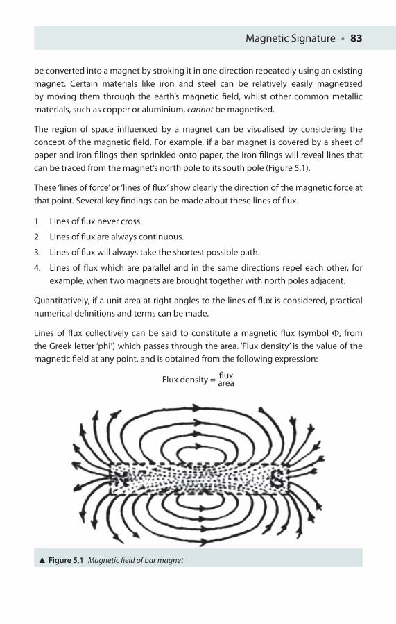
Magnetic Signature • 83
be converted into a magnet by stroking it in one direction repeatedly using an existing magnet. Certain materials like iron and steel can be relatively easily magnetised by moving them through the earth’s magnetic fi eld, whilst other common metallic materials, such as copper or aluminium, cannot be magnetised.
The region of space infl uenced by a magnet can be visualised by considering the concept of the magnetic fi eld. For example, if a bar magnet is covered by a sheet of paper and iron fi lings then sprinkled onto paper, the iron fi lings will reveal lines that can be traced from the magnet’s north pole to its south pole (Figure 5.1).
These ‘lines of force’ or ‘lines of fl ux’ show clearly the direction of the magnetic force at that point. Several key fi ndings can be made about these lines of fl ux.
1. Lines of fl ux never cross.
2. Lines of fl ux are always continuous.
3. Lines of fl ux will always take the shortest possible path.
4. Lines of fl ux which are parallel and in the same directions repel each other, for example, when two magnets are brought together with north poles adjacent.
Quantitatively, if a unit area at right angles to the lines of fl ux is considered, practical numerical defi nitions and terms can be made.
Lines of fl ux collectively can be said to constitute a magnetic fl ux (symbol Φ, from the Greek letter ‘phi’) which passes through the area. ‘Flux density’ is the value of the magnetic fi eld at any point, and is obtained from the following expression:
Flux density = fl ux ____ area
Figure 5.1 Magnetic fi eld of bar magnet
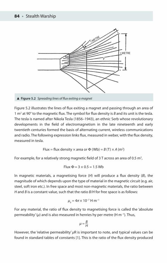
84 • Stealth Warship
Figure 5.2 illustrates the lines of fl ux exiting a magnet and passing through an area of 1 m2 at 90° to the magnetic fl ux. The symbol for fl ux density is B and its unit is the tesla. The tesla is named after Nikola Tesla (1856–1943), an ethnic Serb whose revolutionary developments in the fi eld of electromagnetism in the late nineteenth and early twentieth centuries formed the basis of alternating current, wireless communications and radio. The following expression links fl ux, measured in weber, with the fl ux density, measured in tesla.
Flux = fl ux density × area or Φ (Wb) = B (T) × A (m2)
For example, for a relatively strong magnetic fi eld of 3 T across an area of 0.5 m2,
Flux Φ = 3 × 0.5 = 1.5 Wb
In magnetic materials, a magnetising force (H) will produce a fl ux density (B), the magnitude of which depends upon the type of material in the magnetic circuit (e.g. air, steel, soft iron etc.). In free space and most non-magnetic materials, the ratio between H and B is a constant value, such that the ratio B/H for free space is as follows:
μ0 = 4π × 10−7 H m−1
For any material, the ratio of fl ux density to magnetising force is called the ‘absolute permeability’ (μ) and is also measured in henries hy per metre (H m−1). Thus,
μ = B __ H
However, the ‘relative permeability’ μR is important to note, and typical values can be found in standard tables of constants [1]. This is the ratio of the fl ux density produced
Figure 5.2 Spreading lines of fl ux exiting a magnet
I METRE
P
I METRE

Magnetic Signature • 85
in a magnetic material to the fl ux density which would be produced in air by the same force, that is,
Relative permeability = absolute permeability
______________________ permeability of free space
μR =
μ __ μ
0
Or rewritten as μ = μ0
μR
The result of this is that permeability diff erences in magnetic materials will tend to concentrate any magnetic fi eld lines present such that these fi eld lines might be described as ‘preferring’ to stay and be drawn into the magnetic media rather than in any non-magnetic media. This is not so dissimilar to the way in which light ‘prefers’ to travel within a high-refractive index media such as glass rather than propagate or travel in a low-refractive index media such as air when it is incident above the critical angle. This concentrating of the magnetic fi eld lines can be described as a magnetic ‘lens’ whose concentrating ability is determined by the relative permeability of the material in question. For example, for some materials such as iron, nickel and cobalt, this value can be extremely large (ranging between 1,000 and 2,000). For some specially constructed materials, the value of the relative permeability can be even higher, with two specialist materials ‘nanoperm’ (a cobalt-based magnetic alloy 2714 A) and ‘metglas’ having values of, respectively, 80,000 and 1,000,000! Interestingly, pure metals such as nickel, cobalt and magnesium exhibit only very slight magnetic properties, but when alloyed with iron very strong magnetic properties will result.
For example, compare the magnetic fl ux (in weber) produced by a given magnetising force of 1,000 H in free space and the magnetic fl ux produced in a quantity of nanoperm with relative permeability of 80,000 across an area of 2 m2.
In free space, B = μ0H = 4π × 10−7 × 1,000 = 4π × 10−4 T and, for the nanoperm,
B = μH = μ0μ
RH = 4π × 10−7 × 8 × 1,000 × 1 × 103 = 32π × 10−1 T.
So the fl ux (in weber) in the free space and nanoperm is given, respectively, as Φ = 4π × 10−4 × 2 = 8π × 10−3 Wb and Φ = 32π × 10−1 × 2 = 64π × 10−1 Wb.
The consequence of this concentration of magnetic fi eld lines is seen in the relationship between moving conductors and the generation of an electric fi eld. A metal ship of iron can be considered to be composed of a series of conductors which cut the earth’s magnetic fi eld to induce an electric fi eld in the assembly of conductors. These current-carrying conductors not only can become magnetised themselves but also can infl uence the region of space around them because of the magnetic fi eld produced by the same current-carrying wires.
86 • Stealth Warship
One solution to this problem is the practical engineering technique of degaussing or, its more modern version, deperming. Degaussing provides a degree of protection from magnetic mines, but the physical explanation is often the least understood of magnetic reduction measures, although degaussing is often considered as simply a process of decreasing or eliminating unwanted magnetic fi elds.
Degaussing Ships’ Hulls
With the introduction of iron ships, the eff ect of the ship’s metal hull on steering compasses was noted very quickly. It was also observed that lightning strikes frequently had an eff ect on compass deviation, which in some extreme cases could completely reverse the ship’s magnetic signature. This phenomenon was fi rst recorded in 1866 by a Mr Evan Hopkins of London, who registered a patent for a process ‘to depolarise iron vessels and leave them thenceforth free from any compass-disturbing infl uence whatever’. However, it was a relatively long period after this before degaussing was to be applied practically to the problem of ship’s magnetisation.
Degaussing of a naval vessel’s hull was fi rst demonstrated by Cmdr Charles Goodeve during the Second World War whilst he was trying to counter German magnetic mines which were proving a deadly threat to the British fl eet. German scientists had succeeded in designing very eff ective mines which could detect a small increase in local magnetic fi eld when a ship’s large steel hull, concentrating the earth’s ever-present magnetic fi eld, was over it. The earth can be considered as a relatively simple dipole magnetic with magnetic lines of force running from north to south. Magnetic lines of forces at the earth’s surface have two key components, a vertical component (Z) and a horizontal component (H), which is itself divided into two components: a longitudinal component along the ship and an athwartship component across the beam of the ship. The medium the fi eld lines pass through, with its specifi c permeability, will aff ect the fi eld strength (the lines of force per unit area). Metal, for example, is more permeable than water. So the fi eld intensity increases in the ship, creating anomalies or localised concentrations in the magnetic fi eld around it, as illustrated with visualised lines of force in Figure 5.3. In reality, the ship will have a composite permeability of diff ering metal components and structures with a three-dimensional spatial distribution.
A further complication is that all ships are built within the earth’s magnetic fi eld, and so they will become permanently magnetised, at least partially. However, the level of permanent magnetisation depends on the earth’s fi eld where the ship was built, its orientation when it was built and the construction materials used.

Magnetic Signature • 87
The induced magnetic fi eld from the ship’s magnetic materials when moving in the earth’s magnetic fi eld will depend upon the earth’s magnetic fi eld strength and the ship’s orientation. The components are ‘longitudinal’ (aff ected by latitude, heading and pitch), ‘athwartship’ (aff ected by latitude, heading and roll) and ‘vertical’ (aff ected by latitude, pitch and roll).
A somewhat complex method can be used to compensate for a ship’s magnetic fi elds by winding high-current-carrying coils around the ships and then passing a direct current (DC) through them. This DC can be used to create a fi eld equal yet opposite to the ship’s magnetic fi eld, making the ship ‘magnetically invisible’. It should be noted that this is not a trivial operation, and is not necessarily a complete success. Diff erent classes of ship, because of their diff erent geometry and diff erent construction materials, will require very diff erent degaussing arrangements. Nonetheless, the key diff erences between these arrangements can be characterised in terms of what power supplies are required and the control circuitry used.
Returning to our discussion of German mines, since the Germans at this time used the Gauss as the unit of strength of the magnetic fi eld in their mine triggering mechanisms (there was not at this time a standardised measure of magnetic fi eld), Goodeve decided to refer to the various processes trialled to counter the mines as degaussing.
Let us take a little closer look at a simplistic layout of coil arrangements that could be more eff ectively achieved by embedding them within the superstructure of a ship’s platform itself (Figure 5.4).
Main coil (M) can be used to eff ectively compensate for the induced and permanent vertical components of a ship’s magnetic fi eld (the so-called Z zone). The main coil is
Figure 5.3 Magnetic fi eld lines concentrated in the steel of the ship © CR Lavers
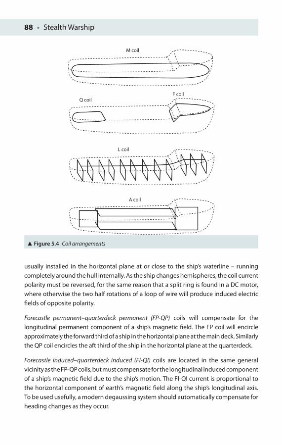
88 • Stealth Warship
usually installed in the horizontal plane at or close to the ship’s waterline – running completely around the hull internally. As the ship changes hemispheres, the coil current polarity must be reversed, for the same reason that a split ring is found in a DC motor, where otherwise the two half rotations of a loop of wire will produce induced electric fi elds of opposite polarity.
Forecastle permanent–quarterdeck permanent (FP-QP) coils will compensate for the longitudinal permanent component of a ship’s magnetic fi eld. The FP coil will encircle approximately the forward third of a ship in the horizontal plane at the main deck. Similarly the QP coil encircles the aft third of the ship in the horizontal plane at the quarterdeck.
Forecastle induced–quarterdeck induced (FI-QI) coils are located in the same general vicinity as the FP-QP coils, but must compensate for the longitudinal induced component of a ship’s magnetic fi eld due to the ship’s motion. The FI-QI current is proportional to the horizontal component of earth’s magnetic fi eld along the ship’s longitudinal axis. To be used usefully, a modern degaussing system should automatically compensate for heading changes as they occur.
M coil
Q coilF coil
L coil
A coil
Figure 5.4 Coil arrangements
Magnetic Signature • 89
An athwartship (A) coil should be installed in the vertical plane and extend from the keel to the main deck. It is designed to compensate for both the athwartship component of magnetic fi eld induced and the athwartship’s permanent component of the ship’s magnetic fi eld. The athwartship coil current consists of permanent and induced components.
The fi rst method of degaussing involves installing electromagnetic coils into the ships, and was termed ‘coiling’. British ships, notably our cruisers and battleships, were well protected in this way by 1943.
However, installing such specialist equipment was still too expensive and diffi cult to service all the ships that really needed it, so the navy developed an alternative called ‘wiping’, which entailed the dragging of a large electrical cable along the ship’s side with a current of about 2,000 A fl owing through it to induce the right fi eld in it! – a potentially dangerous proposition for engineers tasked with achieving this reduction in fi eld. It was initially thought that the pounding of the sea, especially during the fi erce winter storms of the North Atlantic, on the ship’s hull and the fi elds produced by the ship’s engines might rapidly randomise this impressed correcting induced fi eld. Fortunately ship tests found this not to be a problem.
After the Second World War, magnetic fuses were improved, which now did not require the mine to detect the absolute value of the magnetic fi eld itself, but changes to it, which improved the overall sensitivity of the mine considerably. This also meant that a generally well-degaussed ship which still retained a small magnetic ‘hot spot’ could trigger a mine. In addition, the precise orientation of the fi eld could now be measured, something a simple bias fi eld could not remove, at least not for all points on a warship. A series of increasingly complex coil arrangements was introduced to off set these eff ects, with modern systems including no fewer than three separate sets of coils to reduce fi elds in all axes.
Deperming is now viewed as a procedure for erasing the permanent magnetism from ships and submarines, in order to ‘camoufl age’ them from a magnetic point of view against magnetic detection vessels and enemy marine mines. Sea-going, metal-hulled ships will nonetheless develop a magnetic signature as they travel due to interaction with earth’s magnetic fi eld, and this signature can still be exploited by magnetic mines or facilitate detection of a submarine by ships or aircraft with magnetic anomaly detection (MAD) equipment. Navies use deperming procedures as a countermeasure against this, and today specialised deperming facilities can perform the procedure. Heavy gauge copper cables are fi rst wrapped round the hull and superstructure of the vessel, and after safety checks are made, very high electrical currents up to 4,000 A (4 kA) are pulsed through the cables. This has the eff ect of ‘resetting’ the ship’s magnetic
90 • Stealth Warship
signature. The process is now suffi ciently sophisticated that it is even possible to assign a specifi c signature that is best suited to the particular area of the world the ship will operate in, but this is not something that can easily be done operationally at sea. Over time, the deperm will start to degrade and the deperming procedure must be repeated periodically to maintain the desired eff ect.
When a ship is close to a magnetic mine or magnetic torpedo, the magnetic fi eld of a ship actuates the fi ring mechanism and will cause the mine or torpedo to explode. Degaussing is thus quite reasonably viewed as a fi tted electrical installation designed to protect a ship against magnetic mines and torpedoes. So, in summary, the purpose of degaussing is to counteract the ship’s magnetic fi eld and establish a condition such that the magnetic fi eld near the ship is, as nearly as possible, the same as if the ship were not there. Degaussing coils are simply large diameter electrical wires which when carrying a large enough current are able to produce an electromagnetic fi eld.
A ship made of ferromagnetic materials such as steel, which as explained earlier concentrate lines of magnetic fl ux, will constrain them to follow a ‘preferred’ path to the water surface. Consequently the local magnetic fi eld of the earth, as stated, can become quite distorted. Magnetic fl ux through a surface is proportional to the number of magnetic fi eld lines passing through the surface. This is the net number, that is, the number passing through in one direction, minus the number passing through in the other direction. Quantitatively, magnetic fl ux through a surface S is defi ned as the integral of the magnetic fi eld over the area of the surface, but this is best omitted in this volume.
As the ship moves, it will have a potential diff erence (p.d.) or voltage induced across its hull plates and superstructure, with diff ering voltages over the entire ship due to the non-uniformities in its original construction and/or subsequent modifi cations. Variations in current fl owing inside the ship will induce magnetic fi elds around it. A metal ship conductor of width L with a velocity v that is in relative motion within a perpendicular magnetic fi eld of fl ux density B will have a voltage of magnitude V = BLv induced across it, where B is measured in tesla (T), L in metres and v in metres per second. A more precise form of the equation will also take into account the angle of the fi eld line to the velocity vector, and it is left to the reader to investigate and consider the consequences of this.
This voltage or potential diff erence across the ends of the conductor will cause a current to fl ow, which in turn produces an induced magnetic fi eld (Figure 5.5). A conductor which carries a current I has a decreasing radial magnetic fi eld of fl ux density B with increasing distance from the wire. Hence a current is applied which creates a magnetic fi eld in the opposite direction to that which has been induced by this motion (Figure 5.6).
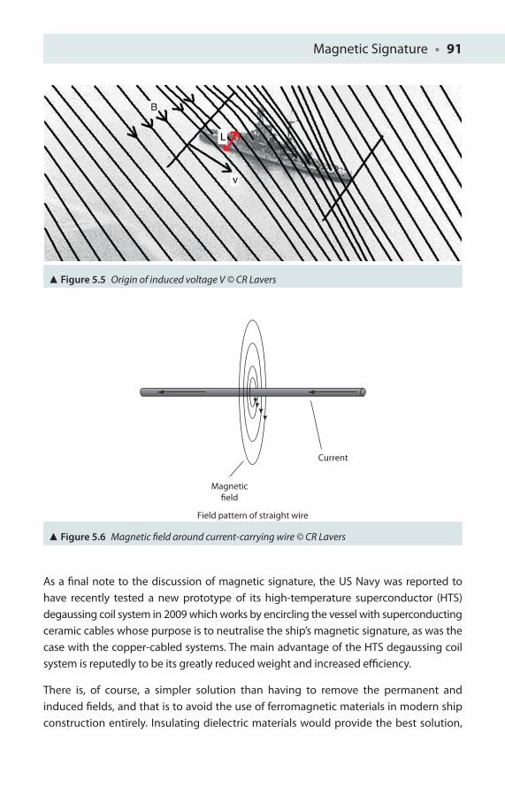
Magnetic Signature • 91
As a fi nal note to the discussion of magnetic signature, the US Navy was reported to have recently tested a new prototype of its high-temperature superconductor (HTS) degaussing coil system in 2009 which works by encircling the vessel with superconducting ceramic cables whose purpose is to neutralise the ship’s magnetic signature, as was the case with the copper-cabled systems. The main advantage of the HTS degaussing coil system is reputedly to be its greatly reduced weight and increased effi ciency.
There is, of course, a simpler solution than having to remove the permanent and induced fi elds, and that is to avoid the use of ferromagnetic materials in modern ship construction entirely. Insulating dielectric materials would provide the best solution,
Figure 5.5 Origin of induced voltage V © CR Lavers
Figure 5.6 Magnetic fi eld around current-carrying wire © CR Lavers
Current
Magneticfield
Field pattern of straight wire
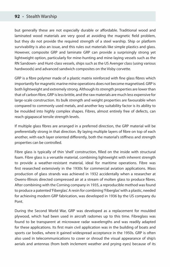
92 • Stealth Warship
but generally these are not especially durable or aff ordable. Traditional wood and laminated wood materials are very good at avoiding the magnetic fi eld problem, but they do not provide the required strength of a steel warship. Ship or platform survivability is also an issue, and this rules out materials like simple plastics and glass. However, composite GRP and laminate GRP can provide a surprisingly strong yet lightweight option, particularly for mine-hunting and mine-laying vessels such as the RN Sandown- and Hunt-class vessels, ships such as the US Avenger class (using various hardwoods) and advanced sandwich composites on the Visby corvette.
GRP is a fi bre polymer made of a plastic matrix reinforced with fi ne glass fi bres which importantly for magnetic marine mine operations does not become magnetised. GRP is both lightweight and extremely strong. Although its strength properties are lower than that of carbon fi bre, GRP is less brittle, and the raw materials are much less expensive for large-scale construction. Its bulk strength and weight properties are favourable when compared to commonly used metals, and another key suitability factor is its ability to be moulded into highly complex shapes. Fibres, almost entirely free of defects, can reach gigapascal tensile strength levels.
If multiple glass fi bres are arranged in a preferred direction, the GRP material will be preferentially strong in that direction. By laying multiple layers of fi bre on top of each another, with each layer oriented diff erently, both the material’s stiff ness and strength properties can be controlled.
Fibre glass is typically of thin ‘shell’ construction, fi lled on the inside with structural foam. Fibre glass is a versatile material, combining lightweight with inherent strength to provide a weather-resistant material, ideal for maritime operations. Fibre was fi rst researched extensively in the 1930s for commercial aviation applications. Mass production of glass strands was achieved in 1932 accidentally when a researcher at Owens-Illinois directed compressed air at a stream of molten glass to produce fi bres. After combining with the Corning company in 1935, a reproducible method was found to produce a patented ‘Fiberglas’. A resin for combining ‘Fiberglas’ with a plastic, needed for achieving modern GRP fabrication, was developed in 1936 by the US company du Pont.
During the Second World War, GRP was developed as a replacement for moulded plywood, which had been used in aircraft radomes up to this time. Fibreglass was found to be transparent at microwave radar wavelengths and was readily adapted for these applications. Its fi rst main civil application was in the building of boats and sports car bodies, where it gained widespread acceptance in the 1950s. GRP is often also used in telecommunications to cover or shroud the visual appearance of ship’s aerials and antennas (from both inclement weather and prying eyes) because of its
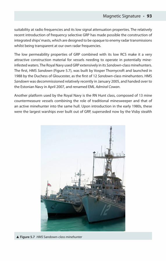
Magnetic Signature • 93
suitability at radio frequencies and its low signal attenuation properties. The relatively recent introduction of frequency selective GRP has made possible the construction of integrated ships’ masts, which are designed to be opaque to enemy radar transmissions whilst being transparent at our own radar frequencies.
The low permeability properties of GRP combined with its low RCS make it a very attractive construction material for vessels needing to operate in potentially mine-infested waters. The Royal Navy used GRP extensively in its Sandown-class minehunters. The fi rst, HMS Sandown (Figure 5.7), was built by Vosper Thornycroft and launched in 1988 by the Duchess of Gloucester, as the fi rst of 12 Sandown-class minehunters. HMS Sandown was decommissioned relatively recently in January 2005, and handed over to the Estonian Navy in April 2007, and renamed EML Admiral Cowan.
Another platform used by the Royal Navy is the RN Hunt class, composed of 13 mine countermeasure vessels combining the role of traditional minesweeper and that of an active minehunter into the same hull. Upon introduction in the early 1980s, these were the largest warships ever built out of GRP, superseded now by the Visby stealth
Figure 5.7 HMS Sandown-class minehunter
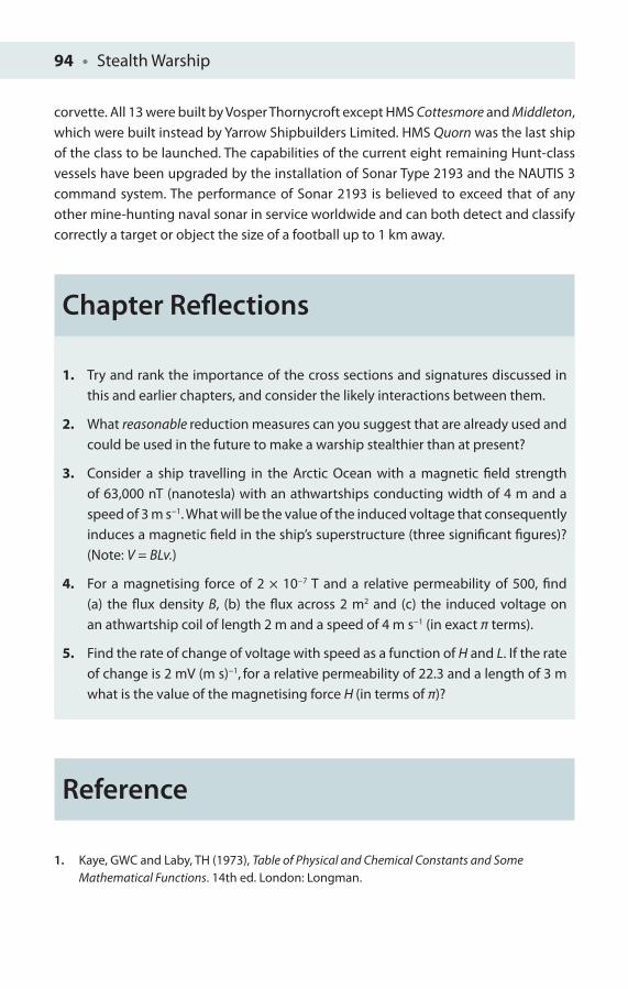
94 • Stealth Warship
corvette. All 13 were built by Vosper Thornycroft except HMS Cottesmore and Middleton, which were built instead by Yarrow Shipbuilders Limited. HMS Quorn was the last ship of the class to be launched. The capabilities of the current eight remaining Hunt-class vessels have been upgraded by the installation of Sonar Type 2193 and the NAUTIS 3 command system. The performance of Sonar 2193 is believed to exceed that of any other mine-hunting naval sonar in service worldwide and can both detect and classify correctly a target or object the size of a football up to 1 km away.
Chapter Refl ections
1. Try and rank the importance of the cross sections and signatures discussed in this and earlier chapters, and consider the likely interactions between them.
2. What reasonable reduction measures can you suggest that are already used and could be used in the future to make a warship stealthier than at present?
3. Consider a ship travelling in the Arctic Ocean with a magnetic fi eld strength of 63,000 nT (nanotesla) with an athwartships conducting width of 4 m and a speed of 3 m s−1. What will be the value of the induced voltage that consequently induces a magnetic fi eld in the ship’s superstructure (three signifi cant fi gures)? (Note: V = BLv.)
4. For a magnetising force of 2 × 10⁻⁷ T and a relative permeability of 500, fi nd (a) the fl ux density B, (b) the fl ux across 2 m2 and (c) the induced voltage on an athwartship coil of length 2 m and a speed of 4 m s−1 (in exact π terms).
5. Find the rate of change of voltage with speed as a function of H and L. If the rate of change is 2 mV (m s)−1, for a relative permeability of 22.3 and a length of 3 m what is the value of the magnetising force H (in terms of π)?
Reference
1. Kaye, GWC and Laby, TH (1973), Table of Physical and Chemical Constants and Some Mathematical Functions. 14th ed. London: Longman.
THE ACOUSTIC THREAT AND
OTHER SIGNATURES
6
The worst wheel of the cart makes the most noise.
Albert Einstein
Acoustic Noise
Blending a ship visually into its background and making modifi cations to both its radar refl ectivity and infra-red emissions are a clear benefi t to ship stealth. Ships, however, are also full of moving equipment generating signifi cant acoustic noise, which can be detected underwater if the sound is transmitted through the hull. Sound can travel very long distances underwater so that ships can be located by submarines, torpedoes or even a sonar dipped from a helicopter. But perhaps the greatest threat to a ship is the silent running submarine menace coupled with the use of anti-sound technology or ‘sonar’.
Sonar is an acronym for sound navigation and ranging, which is a well-developed technique similar to above-water radar, but instead of transmitting electromagnetic waves uses sound propagation underwater for roles such as navigation and mine detection. There are two main types of sonar technology in common naval use today: the so-called ‘passive’ sonar, essentially listening to sounds generated from surface vessels and submarines, and ‘active’ sonar, which emits pulses of sound energy from
96 • Stealth Warship
a transducer and then listens for returning echoes. The time between transmission and reception of an underwater echo enables a sonar operator to establish the range of the underwater contact. Sonar is frequently used as a means of acoustic location, and because of the typical broad frequency spread of a typical ship platform’s echo characteristics, can even identify targets which are not possible from receipt of a corresponding radar echo alone. It is interesting historically that acoustic location in air was used long before radar, and was still in use relatively late in the Second World War by the Japanese, whose huge ‘tuba-like’ apparatuses, each the size of a house, were used to listen as early warning detectors for incoming US bomber aircraft. The acoustic frequencies detected by modern sonar systems, however, are extremely varied, ranging from very low frequencies below the range of human hearing (the so-called ‘infrasonic frequencies’) up to extremely high frequencies above the range of human hearing (or ultrasonic frequencies). It should be noted that the spectrum of frequencies heard by the human ear in air is not the same as that detected under water, for several reasons: diff erences in water absorption being the principal reason and, second, for waves incident from above the waterline, due to change in wave speed. The study of underwater sound is generally referred to as ‘underwater acoustics’ or ‘hydroacoustics’, and is a key part of modern anti-submarine and anti-ship-based warfare.
Although cetaceans such as whales and dolphins use sound for communication and precise fi sh location in the world’s oceans, mankind’s entrance into this arena is only relatively recent. The fi rst verifi ed measurement of sound underwater was in 1490 by Leonardo da Vinci who used a tube inserted into water, and it was reputed he could detect vessels in his vicinity by simply placing his ear to the tube [1].
Interest in radio, radar and the use of sound to ‘echo locate’ objects underwater seems to have been given impetus after the Titanic disaster of 1912. The world’s fi rst patent for an underwater echo ranging device was registered by the English meteorologist Lewis Richardson just a month after the Titanic sank [2], and a German physicist Alexander Behm quickly followed suit with a patent for design of a prototype echo sounder in 1913. Early work in 1912 by Mr Reginald Fessenden, a Canadian engineer working for the Submarine Signal Company in Boston, was noted by the British, who recognised the potential naval benefi ts of this technology. In 1914, Fessenden demonstrated depth sounding, underwater Morse communications and iceberg detection at a surprisingly good 3 km range. Consequently by 1915 the newest Canadian-built Royal Naval H-class submarines were equipped with Fessenden oscillators [3]. Despite their cramped size and lack of deck guns, these H-class submarines were popular amongst submariners, and saw action in British waters and the Adriatic, losing only four of their own in the First World War combat.
The Acoustic Threat and Other Signatures • 97
Meanwhile under the leadership of another Canadian physicist Robert William Boyle, a prototype system for active sound detection was produced for trials in 1917. This work took place under maximum security, and used quartz piezoelectric crystals to produce the world’s fi rst underwater active sound detection system. To maintain this secrecy, no mention of sound experimentation or quartz was made – the word instead used to describe this early work was ‘ASD’ics, hence the initial British use of the acronym ASDIC.
At the start of the Second World War, British ASDIC technology was made freely available to the United States, as part of a pooling of collaborative research, a partnership which also saw the development of the atomic bomb (with the help again of Canada) under the Manhattan Project. Research on ASDIC and underwater sound was signifi cantly expanded by this cooperative act between the United Kingdom and the United States. It is about this time, in the late 1930s, that the Americans began to use the now more widely used term ‘sonar’ for the fi rst time. Many new types of military sound detection systems were consequently developed, which included sonobuoys, developed by the British in 1944 under the codename ‘High Tea’, dipping sonar and, most importantly, mine detection sonar. This work also formed the basis for most post-war developments related to countering the Soviet nuclear submarine threat. In recent years, the main military development has been the increasing interest in low-frequency active systems.
Various Environmental Factors
The underwater environment is generally a much messier and unpredictably changing environment than the above-water environment, being at best a ‘foggy day’ under most circumstances. Sonar detection, classifi cation and location performance depend unsurprisingly on this environment, as well as the receiver and transmitter subsystems used, and for passive sonar, the critical target (ship or submarine’s) radiated noise. Sonar operation is also aff ected by variations in sound speed, which travels more slowly in fresh water (less dense) than in sea water (more dense). Speed is also determined by the water’s Temperature, dissolved impurities (principally Salinity) and Pressure (or STP).
Sonar prediction is diffi cult to achieve but as sound is still bent or refracted in accordance with Snell’s law likely threat ranges for a given set of STP conditions can be made. If conditions are right, propagation may occur in deep sound channels which provide extremely low propagation loss to a sonar receiver within the channel, in a similar way to radar ducts in the above-water environment. Sound propagation is also aff ected by
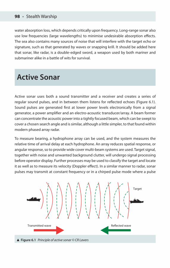
98 • Stealth Warship
water absorption loss, which depends critically upon frequency. Long-range sonar also use low frequencies (large wavelengths) to minimise undesirable absorption eff ects. The sea also contains many sources of noise that will interfere with the target echo or signature, such as that generated by waves or snapping krill. It should be added here that sonar, like radar, is a double-edged sword, a weapon used by both mariner and submariner alike in a battle of wits for survival.
Active Sonar
Active sonar uses both a sound transmitter and a receiver and creates a series of regular sound pulses, and in between them listens for refl ected echoes (Figure 6.1). Sound pulses are generated fi rst at lower power levels electronically from a signal generator, a power amplifi er and an electro-acoustic transducer/array. A beam former can concentrate the acoustic power into a tightly focused beam, which can be swept to cover a chosen search angle and is similar, although a little simpler, to that found within modern phased array radar.
To measure bearing, a hydrophone array can be used, and the system measures the relative time of arrival delay at each hydrophone. An array reduces spatial response, or angular response, so to provide wide cover multi-beam systems are used. Target signal, together with noise and unwanted background clutter, will undergo signal processing before operator display. Further processes may be used to classify the target and locate it as well as to measure its velocity (Doppler eff ect). In a similar manner to radar, sonar pulses may transmit at constant frequency or in a chirped pulse mode where a pulse
Target
Reflected waveTransmitted wave
Figure 6.1 Principle of active sonar © CR Lavers
The Acoustic Threat and Other Signatures • 99
increases in frequency throughout its duration (a technique used in ultrasound by bats). Simple sonar generally use the former with a fi lter suffi ciently wide to cover possible target movement Doppler changes, while more complex ones include the latter. As digital processing has become more widely available, pulse compression is now more common. Military sonar often use multiple beams to provide all-round coverage while simple ones only cover a narrow arc, although a beam may be rotated, relatively slowly, by mechanical scanning or quickly electronically via phased steering. Particularly when single frequency transmission is used, the Doppler eff ect can measure a target’s radial speed. The diff erence in frequency between the transmitted and received signal is measured and is converted into a radial velocity vector.
For a modern warship, the importance of minimising emitted sound cannot be underestimated. Any piece of machinery incorrectly mounted can provide telltale signs of its presence to the watchful scrutiny of the practised sonar operator. In combat situations, an active pulse can be detected by an opponent and might crucially reveal a submarine’s position, and hence passive sonar will be generally used instead.
Passive Sonar
Passive sonar listens without transmitting and is frequently employed by navies worldwide. Passive sonar benefi ts are that as no pulses are transmitted there is no direct risk of compromise to its stealth, be it a ship or submarine platform. However, a lack of timed echoes means that no range, or range resolution information, is directly available from the surrounding environment and other non-transmitting platforms and objects will not necessary show up on the passive sonar display to the operator. This is, of course, a similar problem for the radar operator who wants to establish a faithful tactical picture of what is around him/her in the real environment. Key detection aspects are built around the characteristic sound emitted by AC and DC transformers and generators on board diff erent platforms. Even intermittent sound sources (such as a dropped tool) may be detectable with passive sonar. Passive sonar systems rely heavily upon having large up-to-date sound databases, but the trained sonar operator can usually classify the signals by ear.
For these reasons, many navies operate submarines fuelled by nuclear reactors that are cooled without pumps, using convection instead to run silently. Vehicles’ propellers are also designed and precisely machined to emit minimal noise. High-speed propellers
100 • Stealth Warship
often create tiny bubbles in the water, and this cavitation has a distinct sound, which we will look at in a little more detail shortly. Sonar hydrophones may be towed behind the ship or submarine in order to reduce the eff ect of noise generated by the vessel itself.
Modern naval warfare makes extensive use of both passive and active sonar from surface vessels and aircraft. The relative benefi ts of using active rather than passive sonar technology depend on the radiated characteristics of the target. In the Second World War, active sonar was used by surface vessels, whilst submarines avoided transmission at almost any cost for fear of revealing their presence and location. The genesis of modern signal-processing passive sonar is now greatly improved for initial stealthy detection. Consequently submarines are now designed to be the quietest vessels ever, with a revolution in propeller blade design, needed since the advent of ever improved sonar systems, both passive and active.
Sonar Comparison
Active sonar gives the exact bearing, and the approximate range, to a target and is used when a platform commander, surface or submarine, determines it is more important to determine the position of a possible threat submarine than it is to conceal his own position. However, the emitting sonar will likely be detected. Having registered the signal, it is possible to identify the sonar equipment used (by its frequency and other characteristics, for example, pulse duration) and its position. Active sonar is similar to radar in that, while it allows detection of targets at a certain range, it enables the emitter to be detected at a greater range, which is not desirable.
As active sonar reveals the presence and position of the operator, and does not allow exact classifi cation of targets, it is rarely used by submarines. When active sonar is used by surface ships or submarines, it is typically activated intermittently to minimise the detection risk. Active sonar, however, is routinely used with disposable sonobuoys dropped in an aircraft’s patrol area or in the vicinity of possible enemy sonar contacts.
In conclusion, passive sonar has many advantages; most importantly, it is silent. Since any vessel makes some noise, the vessel may in principle be detected, depending on the level of platform sound emitted and the ambient background noise level in the area, as well as the technology used. A ship or submarine sonar also has a limited

The Acoustic Threat and Other Signatures • 101
fi eld of vision, which can infl uence detection. On a submarine, nose-mounted passive sonar detects in arc range of about 270°, centred on the ship’s long axis, and for a hull-mounted array of about 160° on each side of this (whilst a towed array drawn behind a submarine platform can provide a full 360°).
Once a signal is detected in a certain direction with the so-called ‘broadband’ detection, it is then possible to analyse any confi rmed target with ‘narrowband’ analysis. As every engine makes a specifi c set of sounds, it is straightforward to identify the target if it is already in the database. Passive sonar is stealthy and very useful, but it is costly and it is generally deployed on high-priority platforms (high-value assets) in the form of sonar arrays to enhance detection. Although the focus of this volume is on ship’s stealth, nonetheless it is diffi cult not to make mention of the complementary area of anti-submarine warfare!
Until relatively recently, ship sonar was usually hull-mounted arrays, either amidships or at the bows. To reduce water fl ow noise further, sonar began to be enclosed in metal frames and then placed within reinforced plastic and rubber. Because of problems of ship noise (self-noise), towed sonar are also used, which have the advantage of being able to be placed deeper in the water, a good distance away from the platform itself. However, there are limits on their use in shallow littoral (coastal) waters. Common sonar arrangements include linear towed arrays or variable depth sonar (VDS) with two- or three-dimensional arrays. One example of a modern active/passive ship towed sonar is the Thales Sonar 2087. Sonar 2087 is a towed array sonar designed to replace the older Sonar 2031 towed array. Sonar 2087 is described by its manufacturer as ‘a towed-array system that enables Type 23 frigates to hunt the latest submarines at considerable distances and locate them beyond the range at which they can launch an attack’ [4]. Sonar 2087 is a low-frequency active sonar (LFAS) and consists of both active and passive sonar arrays, manufactured by Thales in the United Kingdom and France. Usually mine countermeasure (MCM) sonar are hull mounted, for example, one example of a hull-mounted MCM sonar is the Type 2193.
The two main threats to ships from sonar-activated devices are torpedoes and mines. Modern torpedoes are often fi tted with active/passive sonar, which can home directly on a target. To deal with these threats torpedo countermeasures are used, which can be towed or moved independently. A modern system used is the UK Royal Navy S2170 Surface Ship Torpedo Defence system. However, mines can also be fi tted with sonar able to detect, locate and recognise targets, making them a very potent threat indeed. Even helicopters can be used in anti-submarine warfare by deploying fi elds of active/passive sonobuoys or by operating dipping sonar, such as the AQS-13 (Figure 6.2).
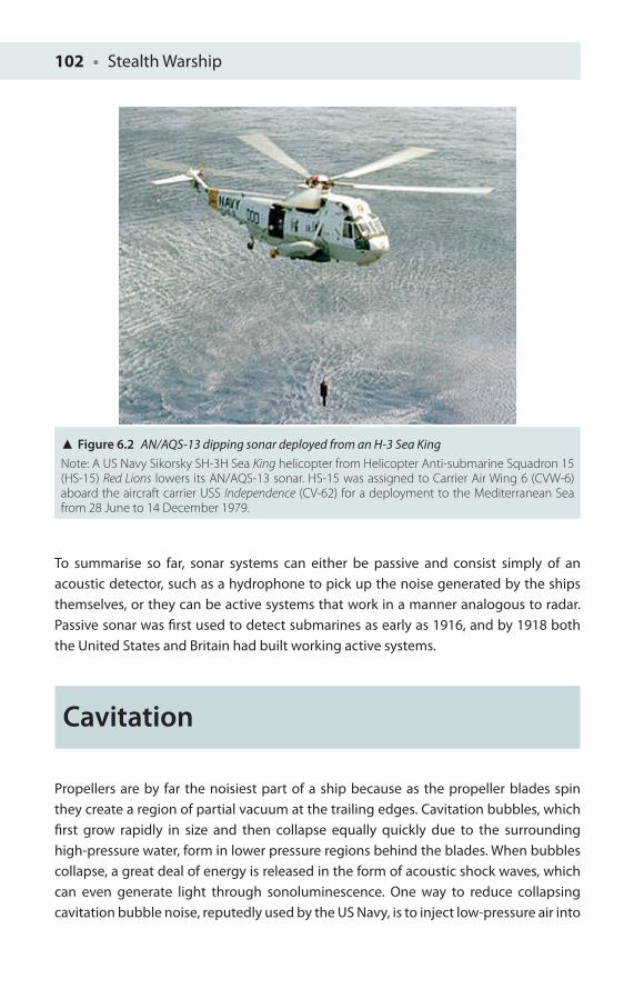
102 • Stealth Warship
To summarise so far, sonar systems can either be passive and consist simply of an acoustic detector, such as a hydrophone to pick up the noise generated by the ships themselves, or they can be active systems that work in a manner analogous to radar. Passive sonar was fi rst used to detect submarines as early as 1916, and by 1918 both the United States and Britain had built working active systems.
Cavitation
Propellers are by far the noisiest part of a ship because as the propeller blades spin they create a region of partial vacuum at the trailing edges. Cavitation bubbles, which fi rst grow rapidly in size and then collapse equally quickly due to the surrounding high-pressure water, form in lower pressure regions behind the blades. When bubbles collapse, a great deal of energy is released in the form of acoustic shock waves, which can even generate light through sonoluminescence. One way to reduce collapsing cavitation bubble noise, reputedly used by the US Navy, is to inject low-pressure air into
Figure 6.2 AN/AQS-13 dipping sonar deployed from an H-3 Sea KingNote: A US Navy Sikorsky SH-3H Sea King helicopter from Helicopter Anti-submarine Squadron 15 (HS-15) Red Lions lowers its AN/AQS-13 sonar. HS-15 was assigned to Carrier Air Wing 6 (CVW-6) aboard the aircraft carrier USS Independence (CV-62) for a deployment to the Mediterranean Sea from 28 June to 14 December 1979.
The Acoustic Threat and Other Signatures • 103
the partial vacuum behind the rotating blades, which reduces the pressure diff erence between the bubbles and surrounding water so that the bubbles collapse more slowly and more quietly. Sweden’s Visby stealth corvette avoids cavitation with water jets instead of propellers. Electric propulsion acoustic insulation also helps to reduce the overall amount of platform acoustic noise, which includes blade rate noise and singing. It is no accident then that there is great emphasis placed upon propeller blade design especially for hunter-killer nuclear-powered submarines to reduce the aff ects of singing, blade rate noise and cavitation. Propulsor systems are now becoming more widespread, having reduced cavitation at high speeds with all moving parts housed in ducts, so very little sound is radiated directly into the marine environment with a more laminar fl ow.
A great emphasis in the Visby is rightly placed on reducing its hydroacoustic signature. Vibrations generated by engines, gearboxes and so on are transmitted to the ship’s superstructure and critically for sonar detection to the hull and from there to the surrounding water and together with the propulsion unit generates the dominant features of the platform’s hydroacoustic signature. Consequently, the technical design specification for a given platform will set certain noise limits against frequency which must be achieved. Similar high technical specifications will be set for other key ship’s parameters. Key areas of potential noise include the low-speed diesel engine, high-speed gas turbine and the main reduction gearbox of the Visby.
Future Acoustic Technology
However, one successful method to silence a noisy piece of machinery in the future could be to simply drill holes in the casing that surrounds it. Workers in Spain noticed a new eff ect – extraordinary acoustic screening (EAS) – while fi ring ultrasonic waves at mm-thick metal plates underwater. When researchers drilled holes in the plates, they found a signifi cant drop in transmission at specifi c frequencies. For ultrasound with a wavelength of 7 mm, a perforated plate reduced transmission by −10 dB more than a solid plate of the same thickness. The plate thickness, its diameter, spacing and hole arrangement all aff ect ultrasound transmission. Holes with the same spacing as the wavelength of sound gave the greatest attenuation [5]. Workers in France have also designed a metamaterial ‘cloak’ for water waves 10 cm across, with a shallow cylindrical ‘metamaterial’ of 700 short posts that splay from the centre in seven concentric rings.
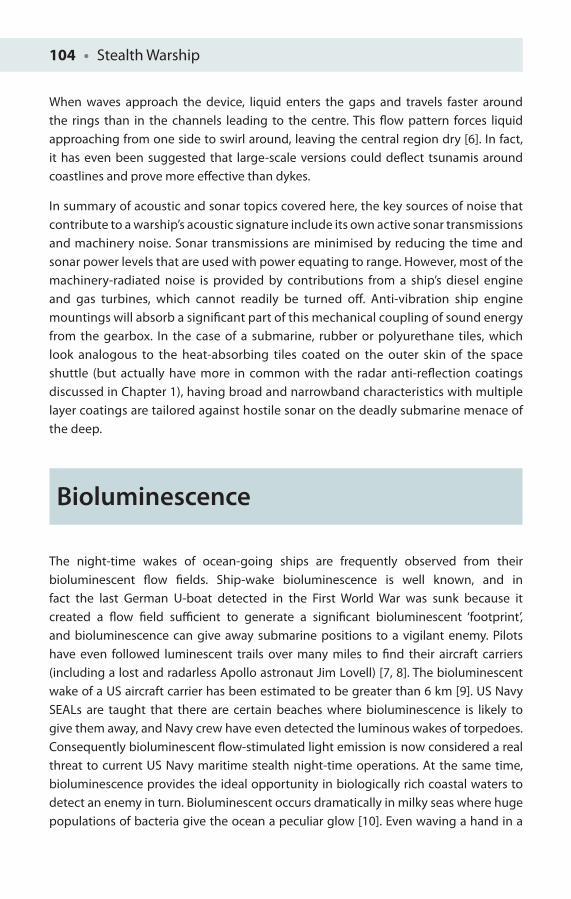
104 • Stealth Warship
When waves approach the device, liquid enters the gaps and travels faster around the rings than in the channels leading to the centre. This fl ow pattern forces liquid approaching from one side to swirl around, leaving the central region dry [6]. In fact, it has even been suggested that large-scale versions could defl ect tsunamis around coastlines and prove more eff ective than dykes.
In summary of acoustic and sonar topics covered here, the key sources of noise that contribute to a warship’s acoustic signature include its own active sonar transmissions and machinery noise. Sonar transmissions are minimised by reducing the time and sonar power levels that are used with power equating to range. However, most of the machinery-radiated noise is provided by contributions from a ship’s diesel engine and gas turbines, which cannot readily be turned off . Anti-vibration ship engine mountings will absorb a signifi cant part of this mechanical coupling of sound energy from the gearbox. In the case of a submarine, rubber or polyurethane tiles, which look analogous to the heat-absorbing tiles coated on the outer skin of the space shuttle (but actually have more in common with the radar anti-refl ection coatings discussed in Chapter 1), having broad and narrowband characteristics with multiple layer coatings are tailored against hostile sonar on the deadly submarine menace of the deep.
Bioluminescence
The night-time wakes of ocean-going ships are frequently observed from their bioluminescent fl ow fi elds. Ship-wake bioluminescence is well known, and in fact the last German U-boat detected in the First World War was sunk because it created a fl ow fi eld suffi cient to generate a signifi cant bioluminescent ‘footprint’, and bioluminescence can give away submarine positions to a vigilant enemy. Pilots have even followed luminescent trails over many miles to fi nd their aircraft carriers (including a lost and radarless Apollo astronaut Jim Lovell) [7, 8]. The bioluminescent wake of a US aircraft carrier has been estimated to be greater than 6 km [9]. US Navy SEALs are taught that there are certain beaches where bioluminescence is likely to give them away, and Navy crew have even detected the luminous wakes of torpedoes. Consequently bioluminescent fl ow-stimulated light emission is now considered a real threat to current US Navy maritime stealth night-time operations. At the same time, bioluminescence provides the ideal opportunity in biologically rich coastal waters to detect an enemy in turn. Bioluminescent occurs dramatically in milky seas where huge populations of bacteria give the ocean a peculiar glow [10]. Even waving a hand in a
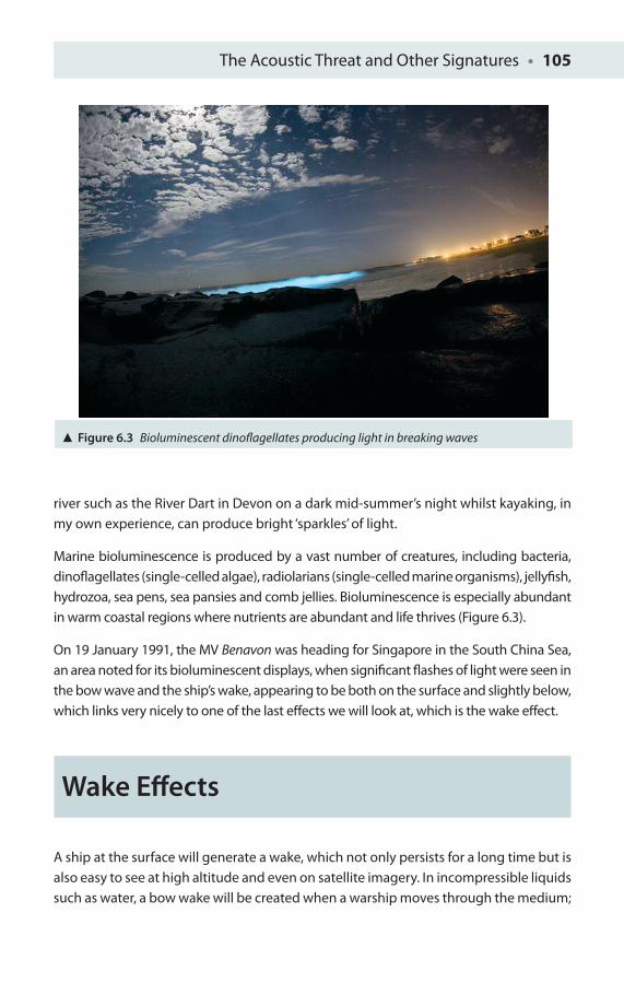
The Acoustic Threat and Other Signatures • 105
river such as the River Dart in Devon on a dark mid-summer’s night whilst kayaking, in my own experience, can produce bright ‘sparkles’ of light.
Marine bioluminescence is produced by a vast number of creatures, including bacteria, dinofl agellates (single-celled algae), radiolarians (single-celled marine organisms), jellyfi sh, hydrozoa, sea pens, sea pansies and comb jellies. Bioluminescence is especially abundant in warm coastal regions where nutrients are abundant and life thrives (Figure 6.3).
On 19 January 1991, the MV Benavon was heading for Singapore in the South China Sea, an area noted for its bioluminescent displays, when signifi cant fl ashes of light were seen in the bow wave and the ship’s wake, appearing to be both on the surface and slightly below, which links very nicely to one of the last eff ects we will look at, which is the wake eff ect.
Wake Eff ects
A ship at the surface will generate a wake, which not only persists for a long time but is also easy to see at high altitude and even on satellite imagery. In incompressible liquids such as water, a bow wake will be created when a warship moves through the medium;
Figure 6.3 Bioluminescent dinofl agellates producing light in breaking waves
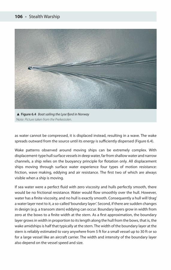
106 • Stealth Warship
as water cannot be compressed, it is displaced instead, resulting in a wave. The wake spreads outward from the source until its energy is suffi ciently dispersed (Figure 6.4).
Wake patterns observed around moving ships can be extremely complex. With displacement-type hull surface vessels in deep water, far from shallow water and narrow channels, a ship relies on the buoyancy principle for fl otation only. All displacement ships moving through surface water experience four types of motion resistance: friction, wave making, eddying and air resistance. The fi rst two of which are always visible when a ship is moving.
If sea water were a perfect fl uid with zero viscosity and hulls perfectly smooth, there would be no frictional resistance. Water would fl ow smoothly over the hull. However, water has a fi nite viscosity, and no hull is exactly smooth. Consequently a hull will ‘drag’ a water layer next to it, a so-called ‘boundary layer’. Second, if there are sudden changes in design (e.g. a transom stern) eddying can occur. Boundary layers grow in width from zero at the bows to a fi nite width at the stern. As a fi rst approximation, the boundary layer grows in width in proportion to its length along the hull from the bows, that is, the wake amidships is half that typically at the stern. The width of the boundary layer at the stern is reliably estimated to vary anywhere from 5 ft for a small vessel up to 30 ft or so for a large vessel like an aircraft carrier. The width and intensity of the boundary layer also depend on the vessel speed and size.
Figure 6.4 Boat sailing the Lyse fj ord in NorwayNote: Picture taken from the Preikestolen.
The Acoustic Threat and Other Signatures • 107
Any object moving through surface water will create a disturbance which is observed as a visible wave pattern. The pattern is ‘fi xed’ or dragged along by the ship like a garment and at high speed is the dominant part of resistance. The pattern consists of two types of waves: ‘divergent’ waves, which start at the bows and stern, and angle aft (wave crests curve and are not straight), and ‘transverse’ waves, which originally start out perpendicular to a ship’s line of motion, but the further away from the ship they are, the more they curve aft.
Based upon careful observation from countless marine observers, it is noted that at the bows water is forced higher up the ship’s side than when further from the hull. This causes the divergent bows wave to be the fi rst to break. The bows wave rises above the at-rest waterline, reaching a peak of about 35–45 ft aft of the stern. Amidships the transverse wave is perhaps a couple of feet below the at-rest waterline, building up to a height of several feet above the at-rest waterline some 34–45 ft forward of the stern. When a divergent wave grows enough in height it breaks, like breaking beach waves. Once waves break, white foam appears in bands parallel to the ship’s side. Foam may extend over 70–80 ft from the sides and persist for several ship’s lengths behind the ship. The presence of the bows wave has been exploited since the First World War by painting false bows waves onto ships to confuse U-boat submarine commanders as to the speed and direction of a vessel.
Researchers at the University of Michigan have studied ship wakes for the US Navy, as wake bubbles are a signifi cant problem which can persist for up to a kilometre behind military vessels. Radar systems now mounted on satellites are suffi ciently sensitive to detect ship wakes. According to Internet sources, the US Navy recently patented a technique that may make ships harder to fi nd by eradicating the bubbles as soon as they appear. As a ship pushes its way through the sea, pockets of air get trapped in the water fl owing round it. These bubbles are caught in strong counter-rotating currents created by the propellers. Big bubbles stay in the wake for only a short time because they are more buoyant, but smaller ones can be caught in the wake for a long time, and it is these small bubbles that make ship wakes easy to spot from the air as they scatter visible light well. In a test to remove bubbles, several transducers injected 1 MHz acoustic waves into water. Waves were produced which interfered with one another, producing a 3D grid of high- and low-pressure pockets. It was found that small bubbles, 0.2 mm across, drifted into low-pressure regions where they then formed bigger bubbles, 1.5 mm across, now with suffi cient buoyancy to fl oat to the surface [11]. However, active production of 1 MHz acoustic waves into water is probably not a practical stealthy solution.
There have also been a number of concerns raised in recent years about the possibilities that high-power naval sonar transducers may either directly or indirectly be responsible for the mass deaths of dolphins and other cetaceans in shallow waters. Loud noises created by sonar may frighten dolphins into shallow waters from which they are later
108 • Stealth Warship
unable to escape. It is also possible that sonar may cause them to surface too quickly while diving, leading to decompression sickness. Certainly it is well known that the loudest military sonar can reach a level of 235 dB, and anything in the above-water environment over 100 dB is documented as being harmful to human hearing. One particular incident in June 2008 was the death of 26 common dolphins stranded in the narrow creaks of the Fal and Helford estuaries, whilst ships of the Dutch, British and German fl eets were conducting exercise 50 miles further south, with helicopter carrying powerful mid-frequency sonar of a type previously linked in the media with the deaths of marine mammals, although no clear evidence was provided. Precautionary enforced measures for acoustic emission control in established dolphin and diving areas are therefore sensible, until this controversy is fi nally resolved.
Extremely Low-Frequency (ELF) Signature
Galvanic currents fl owing in the hull and in the water around the hull can generate underwater electrical potentials. Under certain conditions, these can cause ELF electrical fi elds to be radiated into the water. Detection of the ELF signature can be prevented by certain basic electrical design measures. Recent research combining ELF electrical signals recorded along with those of hydroacoustic detection is even now producing a greater level of sophistication in target detection and identifi cation than ever before [12]. In this work, classifi cation using data-fusion on real underwater signatures from surface ships enabled discrimination between small and big ships based on features extracted from ELF electric (ELFE) and hydroacoustic signatures. A data set was recorded and analysed in the Baltic Sea off the coast of Sweden for 23 passages of surface ships of various size, divided into small (up to 21,484) and big (above 21,484) tons displacement.
Likely Future Cross Sections
In the future, further exploitation of the ultraviolet (UV) spectrum is anticipated for advanced forms of airborne missile detection and possibly surface combatant detection as well. Although terahertz (1012 Hz) active imaging is becoming well established in
The Acoustic Threat and Other Signatures • 109
airport baggage screening (alongside X-ray methods), as well as for medical and dentistry applications, it is wrong to think of it as a panacea for all imaging issues and is an unlikely candidate for maritime operations, except perhaps for extremely short-range, above-water terminal guidance imaging. It would be unable to penetrate the metal hulls of most platforms to provide any internal structural details. Terrestrial and sub-surface very low frequency (VLF) imaging, however, has been conducted from exotic ionospheric stimulated microwave transmissions in the Arctic and has been able to successfully image underground mine workings in Alaska, but this is on a larger scale than examination of internal ship’s compartments combined with the diffi culty of producing intense ELF waves without exciting the earth’s ionospheric ring current! However, this may provide avenues of research for maritime sensing as well.
Platforms may incorporate more natural or synthetic materials, such as multiple wavelength coatings that are becoming increasingly necessary, notably of visible, infra-red and microwave wavelengths, stretching the ingenuity of the coating engineers to the limit to provide a near optimum response across all threat wavelengths. Active RAM would be an attractive possibility for the future or a surface skin which could act as a large area ‘living ear’ to listen for long-range search radar pulse characteristics and then reradiate low amplitude but out-of-phase pulses to cancel the enemy radar echoes. Such an outer ‘skin’ would be able to respond, ‘chameleon-like’, to changes in local environment. Future technologists may also utilise the abundance of water in the maritime environment for numerous activities, such as directed ‘walls of water’ for close-range missile defence (as discussed earlier), mist-sprays to defeat the electro-optics of future sophisticated guided missiles, or to provide ‘ice packs’ on Arctic patrol vessels to insulate heat from external thermal imagery detection. Of all these sensing methods under development, it is likely that satellite tracking of ships in visible, near infra-red, radar and thermal bands will become more commonplace over the next decade, driven in part in the fi rst instance by market forces associated with anti-piracy policing in the troublesome Gulf waters off Somalia and Yemen, and the South China Seas.
Biologically Inspired Design
Biologically inspired design involves using biological principles to solve engineering design problems, such as replicating the lotus petal’s extreme water-repellence (or superhydrophobicity), and is ideal for washing pathogens/chemicals off warship surfaces. Super hydrophobic surfaces have contact angles greater than 150°, showing
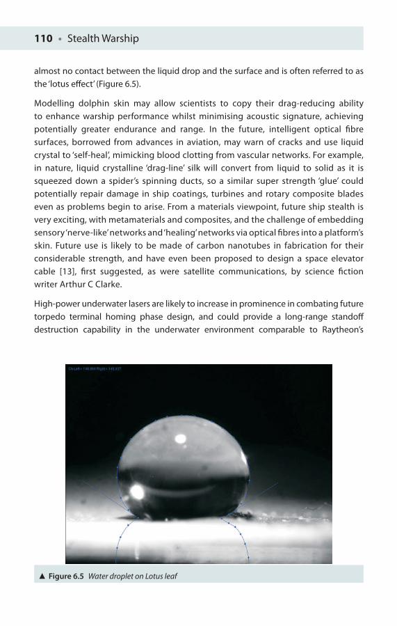
110 • Stealth Warship
almost no contact between the liquid drop and the surface and is often referred to as the ‘lotus eff ect’ (Figure 6.5).
Modelling dolphin skin may allow scientists to copy their drag-reducing ability to enhance warship performance whilst minimising acoustic signature, achieving potentially greater endurance and range. In the future, intelligent optical fi bre surfaces, borrowed from advances in aviation, may warn of cracks and use liquid crystal to ‘self-heal’, mimicking blood clotting from vascular networks. For example, in nature, liquid crystalline ‘drag-line’ silk will convert from liquid to solid as it is squeezed down a spider’s spinning ducts, so a similar super strength ‘glue’ could potentially repair damage in ship coatings, turbines and rotary composite blades even as problems begin to arise. From a materials viewpoint, future ship stealth is very exciting, with metamaterials and composites, and the challenge of embedding sensory ‘nerve-like’ networks and ‘healing’ networks via optical fi bres into a platform’s skin. Future use is likely to be made of carbon nanotubes in fabrication for their considerable strength, and have even been proposed to design a space elevator cable [13], fi rst suggested, as were satellite communications, by science fi ction writer Arthur C Clarke.
High-power underwater lasers are likely to increase in prominence in combating future torpedo terminal homing phase design, and could provide a long-range standoff destruction capability in the underwater environment comparable to Raytheon’s
Figure 6.5 Water droplet on Lotus leaf
The Acoustic Threat and Other Signatures • 111
prototype solid-state laser area defence system (LADS), which ‘successfully detonated 60-mm mortars at ranges greater than 550 yards’ in 2007 above water.
Advanced chemical sensing systems, mounted on high-altitude aircraft, satellite and unmanned aerial vehicles, may also allow the telltale chemical emissions of platforms, nuclear isotopes and Cherenkov radiation (especially from surfaced or near surface ‘leaky’ submarines) to be detected at considerable altitude. Recent research has shown that ship tracks may be detected by the use of ATSR-2 satellite imagery as ships modify cloud microphysics by adding cloud condensation nuclei (CCN) to a developing or any existing cloud. These create lines of larger refl ectance in cloud fi elds that are observed in satellite imagery. In this way, ships are frequently seen off the West Coast of California, the Atlantic coast of West Africa and South West Europe [14], through cloud area amplifi cation, making it easier in one sense to see a ship from its trails than with the use of high-resolution satellite imagery to achieve ship detection, which still requires detailed image analysis to fi nd vessels hidden in a vast ocean.
Emissions Control Policy
Clearly with so many possible diff erent types of sensor emission from a platform, be they active signatures or passive cross sections, we would be wise to consider the impact of communications equipment used onboard and the overall coordination of all of the ship’s sensors and communications to have an Emissions Control Policy in place at all times with various enforced states to ensure that all emissions are kept to as low a level as strictly necessary for the conditions and operations. A ship’s stealth should not be compromised by operator error.
Overall electronic stealth design has become increasingly sophisticated, encompassing many cross sections and signatures. The ongoing confl ict between off ensive and defensive capability will continue this trend, requiring the design of further stealthier platforms. The ideal of a warship which cannot be detected is unlikely to be achieved across all energy bands simultaneously, but it is less likely to be detected if signatures are minimised and increases the probability that decoys and electronic countermeasures will be more eff ective against enemy threats. In most cases, this ‘husbandry’ of emissions is simple, comprising easily applied safety issues which can readily counter any unwitting ‘ignorance’, such as the use of a mobile phone on the quarterdeck at a time of rising tension. However, sophisticated electronic systems are quite capable of generating fake or pre-recorded radio emissions to saturate the airwaves and saturate an enemy’s ability to handle the communications traffi c.
112 • Stealth Warship
Chapter Refl ections
References
1. Fahy, F (1998), Fundamentals of Noise and Vibration. Frank Fahy and John Gerard Walker (eds). Taylor & Francis, Oxford, UK. pp. 375. ISBN 0419241809.
2. Hill, MN (1962), Physical Oceanography. Allan R. Robinson (ed.). Harvard University Press , Harvard, USA. pp. 498.
3. Seitz, F (1999), The Cosmic Inventor: Reginald Aubrey Fessenden (1866–1932), vol. 89. American Philosophical Society, Philadelphia, USA. pp. 41–46. ISBN 087169896X.
4. http://www2.thalesgroup.com/blogs/farnborough2010/fi les/2010/07/HMS-Sutherlands-Sonar-Impresses-on-First-Major-Test.pdf (accessed 22 May 2012).
5. Estrada, H, Candelas, P, Uris, A, Belmar, F, Garcıa de Abajo, FJ and Meseguer, F (2008), ‘Extraordinary sound screening in perforated plates’, Physical Review Letters, 101(8): 084302.
6. Farhat, M, Enoch, S, Guenneau, S and Movchan, AB (2008), ‘Broadband cylindrical acoustic cloak for linear surface waves in a fl uid’, Physical Review Letters, 101(13): 134501.
7. Bityukov, EP (1971), ‘Bioluminescence in the wake of a ship in the Atlantic Ocean and Mediterranean Sea and Black Sea’, Okeanologiya, 11(11): 127–133.
8. Hastings, JW (1993), ‘Dinofl agellates: Cell biochemistry and its regulation of the millisecond and 24-hour time scale’, Naval Research Reviews – Bioluminescence in the Sea, XLV(2): 21–30.
9. Rohr, J, Hyman, M, Fallon, S and Latz, MI (2002), ‘Bioluminescence fl ow visualization in the ocean: An initial strategy based on laboratory experiments’, Deep-Sea Research, Part I: Oceanographic Research Papers, 49(11): 2009–2033.
10. Miller, SD, Haddock, HD, Elvidge, CD and Lee, TF (2006), ‘Twenty thousand leagues over the seas: The fi rst satellite perspective on bioluminescent “milky seas”’, International Journal of Remote Sensing, 27(23–24): 5131–5143.
11. http://www.marinetalk.com/articles-marine-companies/art/Removing-a-Ships-Wake-xxx00095309TU.html.
1 Consider the benefi ts of an electromagnetic fi nal terminal phase for a hypothetical underwater threat.
2 What laser wavelengths might be the best suited to such a threat as that suggested in Point 1 and also for design of appropriate laser-based countermeasures?

The Acoustic Threat and Other Signatures • 113
12. Lennartsson, RK, Dalberg, E, Levonen, MJ, Lindgren, D and Persson, L (2007), Fused Classifi cation of Surface Ships Based on Hydroacoustic and Electromagnetic Signatures. OCEANS 2006 – Asia Pacifi c, ISBN:978-1-4244-0138-3.
13. Pugno, NM (2006), ‘On the strength of the carbon nanotube-based space elevator cable: From nanomechanics to megamechanics’, Journal of Physics: Condensed Matter, 18(33): S1971–S1990.
14. Campmany, E, Grainger, RG and Dean, SM (2008), ‘Detection of ship tracks in ATSR2 satellite imagery’, Atmospheric Chemistry and Physics Discussion, 8(4): 14819–14839.
7MODERN STEALTH SHIPS
To see and yet be unseen, this is the very heart of stealth.
Chris Lavers
This chapter will look at the current generation of warships and marine vessels as well as the latest prototypes. I will leave future ideas and developments for the reader in the next chapter. Amongst the vessels to be covered here are the Swedish Visby stealth corvette, the UK Type 45 Destroyer and its French and Italian variants, the French La Fayette-class frigate, and the US M80 Stiletto. Of course, by the very nature of stealth, there may be platforms under development that are not mentioned here, simply because we do not know about them yet!
Sweden
Visby
The Visby stealth corvette is named after Visby in Gotland County, Sweden (Figure 7.1). It is probably the best preserved medieval city in Scandinavia and a World Heritage Site. The name ‘Visby’ comes from the Old Norse Vis, meaning ‘sacrifi cial place’, and by, meaning ‘city’.
The Swedish Navy’s Visby-class corvettes are claimed to be the fi rst operational naval vessels in the world to use fully developed stealth technology to minimise all the
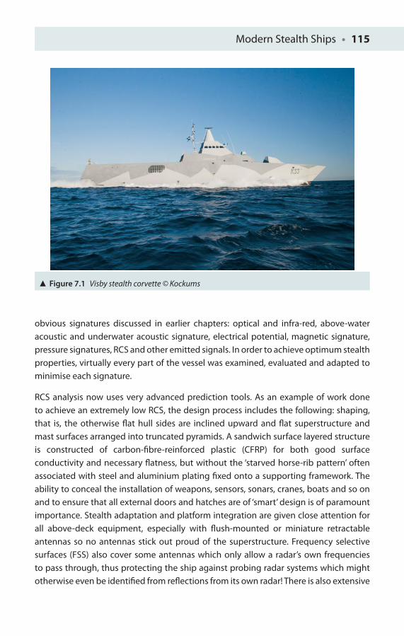
Modern Stealth Ships • 115
obvious signatures discussed in earlier chapters: optical and infra-red, above-water acoustic and underwater acoustic signature, electrical potential, magnetic signature, pressure signatures, RCS and other emitted signals. In order to achieve optimum stealth properties, virtually every part of the vessel was examined, evaluated and adapted to minimise each signature.
RCS analysis now uses very advanced prediction tools. As an example of work done to achieve an extremely low RCS, the design process includes the following: shaping, that is, the otherwise fl at hull sides are inclined upward and fl at superstructure and mast surfaces arranged into truncated pyramids. A sandwich surface layered structure is constructed of carbon-fi bre-reinforced plastic (CFRP) for both good surface conductivity and necessary fl atness, but without the ‘starved horse-rib pattern’ often associated with steel and aluminium plating fi xed onto a supporting framework. The ability to conceal the installation of weapons, sensors, sonars, cranes, boats and so on and to ensure that all external doors and hatches are of ‘smart’ design is of paramount importance. Stealth adaptation and platform integration are given close attention for all above-deck equipment, especially with fl ush-mounted or miniature retractable antennas so no antennas stick out proud of the superstructure. Frequency selective surfaces (FSS) also cover some antennas which only allow a radar’s own frequencies to pass through, thus protecting the ship against probing radar systems which might otherwise even be identifi ed from refl ections from its own radar! There is also extensive
Figure 7.1 Visby stealth corvette © Kockums
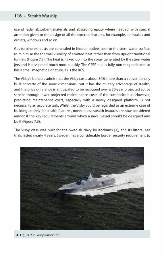
116 • Stealth Warship
use of radar absorbent materials and absorbing epoxy where needed, with special attention given to the design of all the external features, for example, air intakes and outlets, windows and so on.
Gas turbine exhausts are concealed in hidden outlets near to the stern water surface to minimise the thermal visibility of emitted heat rather than from upright traditional funnels (Figure 7.2). The heat is mixed up into the spray generated by the stern water jets and is dissipated much more quickly. The CFRP hull is fully non-magnetic and so has a small magnetic signature, as is the RCS.
The Visby’s builders admit that the Visby costs about 50% more than a conventionally built corvette of the same dimensions, but it has the military advantage of stealth, and the price diff erence is anticipated to be recouped over a 30-year projected active service through lower projected maintenance costs of the composite hull. However, predicting maintenance costs, especially with a newly designed platform, is not necessarily an accurate task. Whilst the Visby could be regarded as an extreme case of building entirely for stealth features, nonetheless stealth features are now considered amongst the key requirements around which a naval vessel should be designed and built (Figure 7.3).
The Visby class was built for the Swedish Navy by Kockums [1], and its littoral sea trials lasted nearly 4 years. Sweden has a considerable border security requirement to
Figure 7.2 Visby © Kockums
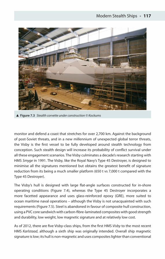
Modern Stealth Ships • 117
monitor and defend a coast that stretches for over 2,700 km. Against the background of post-Soviet threats, and in a new millennium of unexpected global terror threats, the Visby is the fi rst vessel to be fully developed around stealth technology from conception. Such stealth design will increase its probability of confl ict survival under all these engagement scenarios. The Visby culminates a decade’s research starting with HMS Smyge in 1991. The Visby, like the Royal Navy’s Type 45 Destroyer, is designed to minimise all the signatures mentioned but obtains the greatest benefi t of signature reduction from its being a much smaller platform (650 t vs 7,000 t compared with the Type 45 Destroyer).
The Visby’s hull is designed with large fl at-angle surfaces constructed for in-shore operating conditions (Figure 7.4), whereas the Type 45 Destroyer incorporates a more facetted appearance and uses glass-reinforced epoxy (GRE), more suited to ocean maritime naval operations – although the Visby is not unacquainted with such requirements (Figure 7.5). Steel is abandoned in favour of composite hull construction, using a PVC core sandwich with carbon-fi bre-laminated composites with good strength and durability, low weight, low magnetic signature and at relatively low cost.
As of 2012, there are fi ve Visby-class ships, from the fi rst HMS Visby to the most recent HMS Karlstaad, although a sixth ship was originally intended. Overall ship magnetic signature is low; its hull is non-magnetic and uses composites lighter than conventional
Figure 7.3 Stealth corvette under construction © Kockums
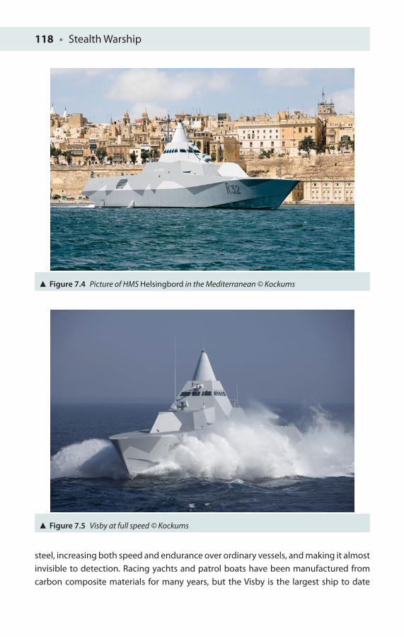
118 • Stealth Warship
Figure 7.4 Picture of HMS Helsingbord in the Mediterranean © Kockums
Figure 7.5 Visby at full speed © Kockums
steel, increasing both speed and endurance over ordinary vessels, and making it almost invisible to detection. Racing yachts and patrol boats have been manufactured from carbon composite materials for many years, but the Visby is the largest ship to date
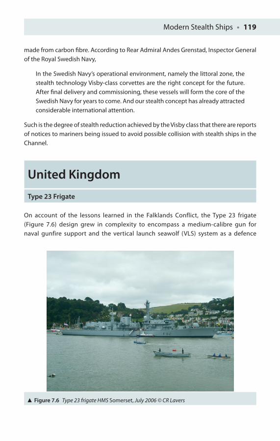
Modern Stealth Ships • 119
made from carbon fi bre. According to Rear Admiral Andes Grenstad, Inspector General of the Royal Swedish Navy,
In the Swedish Navy’s operational environment, namely the littoral zone, the stealth technology Visby-class corvettes are the right concept for the future. After fi nal delivery and commissioning, these vessels will form the core of the Swedish Navy for years to come. And our stealth concept has already attracted considerable international attention.
Such is the degree of stealth reduction achieved by the Visby class that there are reports of notices to mariners being issued to avoid possible collision with stealth ships in the Channel.
United Kingdom
Type 23 Frigate
On account of the lessons learned in the Falklands Conflict, the Type 23 frigate (Figure 7.6) design grew in complexity to encompass a medium-calibre gun for naval gunfire support and the vertical launch seawolf (VLS) system as a defence
Figure 7.6 Type 23 frigate HMS Somerset, July 2006 © CR Lavers
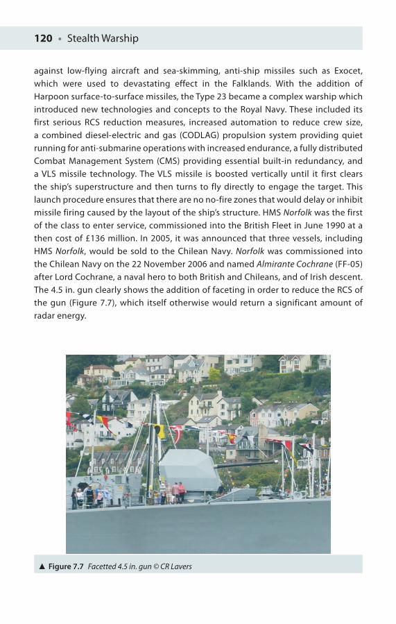
120 • Stealth Warship
against low-flying aircraft and sea-skimming, anti-ship missiles such as Exocet, which were used to devastating effect in the Falklands. With the addition of Harpoon surface-to-surface missiles, the Type 23 became a complex warship which introduced new technologies and concepts to the Royal Navy. These included its first serious RCS reduction measures, increased automation to reduce crew size, a combined diesel-electric and gas (CODLAG) propulsion system providing quiet running for anti-submarine operations with increased endurance, a fully distributed Combat Management System (CMS) providing essential built-in redundancy, and a VLS missile technology. The VLS missile is boosted vertically until it first clears the ship’s superstructure and then turns to fly directly to engage the target. This launch procedure ensures that there are no no-fire zones that would delay or inhibit missile firing caused by the layout of the ship’s structure. HMS Norfolk was the first of the class to enter service, commissioned into the British Fleet in June 1990 at a then cost of £136 million. In 2005, it was announced that three vessels, including HMS Norfolk, would be sold to the Chilean Navy. Norfolk was commissioned into the Chilean Navy on the 22 November 2006 and named Almirante Cochrane (FF-05) after Lord Cochrane, a naval hero to both British and Chileans, and of Irish descent. The 4.5 in. gun clearly shows the addition of faceting in order to reduce the RCS of the gun (Figure 7.7), which itself otherwise would return a significant amount of radar energy.
Figure 7.7 Facetted 4.5 in. gun © CR Lavers
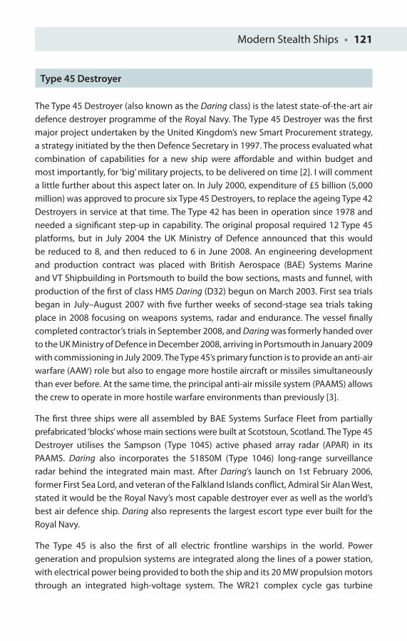
Modern Stealth Ships • 121
Type 45 Destroyer
The Type 45 Destroyer (also known as the Daring class) is the latest state-of-the-art air defence destroyer programme of the Royal Navy. The Type 45 Destroyer was the fi rst major project undertaken by the United Kingdom’s new Smart Procurement strategy, a strategy initiated by the then Defence Secretary in 1997. The process evaluated what combination of capabilities for a new ship were aff ordable and within budget and most importantly, for ‘big’ military projects, to be delivered on time [2]. I will comment a little further about this aspect later on. In July 2000, expenditure of £5 billion (5,000 million) was approved to procure six Type 45 Destroyers, to replace the ageing Type 42Destroyers in service at that time. The Type 42 has been in operation since 1978 and needed a signifi cant step-up in capability. The original proposal required 12 Type 45 platforms, but in July 2004 the UK Ministry of Defence announced that this would be reduced to 8, and then reduced to 6 in June 2008. An engineering development and production contract was placed with British Aerospace (BAE) Systems Marine and VT Shipbuilding in Portsmouth to build the bow sections, masts and funnel, with production of the fi rst of class HMS Daring (D32) begun on March 2003. First sea trials began in July–August 2007 with fi ve further weeks of second-stage sea trials taking place in 2008 focusing on weapons systems, radar and endurance. The vessel fi nally completed contractor’s trials in September 2008, and Daring was formerly handed over to the UK Ministry of Defence in December 2008, arriving in Portsmouth in January 2009 with commissioning in July 2009. The Type 45’s primary function is to provide an anti-air warfare (AAW) role but also to engage more hostile aircraft or missiles simultaneously than ever before. At the same time, the principal anti-air missile system (PAAMS) allows the crew to operate in more hostile warfare environments than previously [3].
The fi rst three ships were all assembled by BAE Systems Surface Fleet from partially prefabricated ‘blocks’ whose main sections were built at Scotstoun, Scotland. The Type 45Destroyer utilises the Sampson (Type 1045) active phased array radar (APAR) in its PAAMS. Daring also incorporates the S1850M (Type 1046) long-range surveillance radar behind the integrated main mast. After Daring’s launch on 1st February 2006, former First Sea Lord, and veteran of the Falkland Islands confl ict, Admiral Sir Alan West, stated it would be the Royal Navy’s most capable destroyer ever as well as the world’s best air defence ship. Daring also represents the largest escort type ever built for the Royal Navy.
The Type 45 is also the fi rst of all electric frontline warships in the world. Power generation and propulsion systems are integrated along the lines of a power station, with electrical power being provided to both the ship and its 20 MW propulsion motors through an integrated high-voltage system. The WR21 complex cycle gas turbine
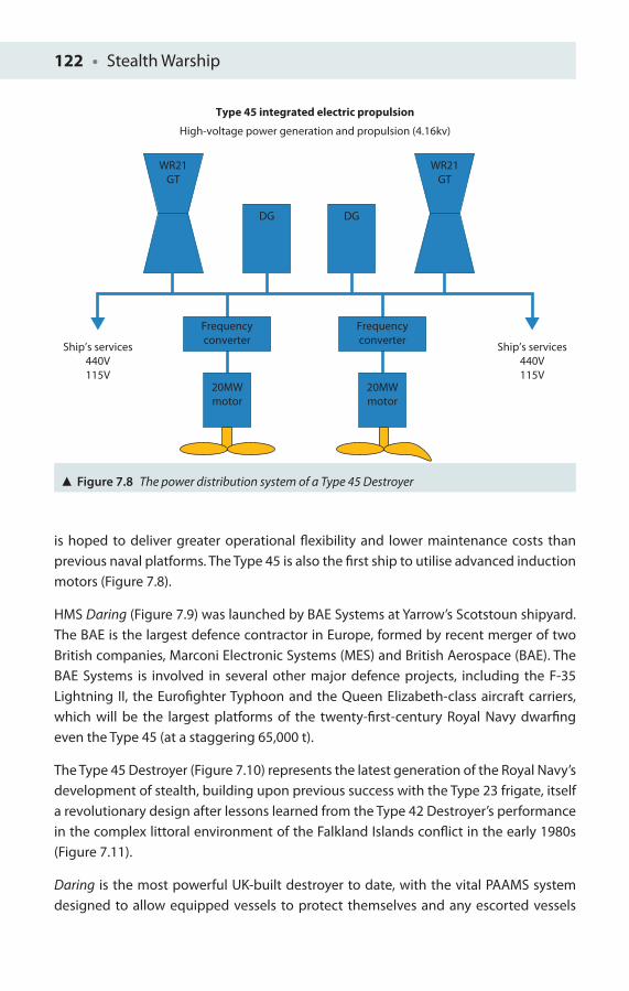
122 • Stealth Warship
is hoped to deliver greater operational fl exibility and lower maintenance costs than previous naval platforms. The Type 45 is also the fi rst ship to utilise advanced induction motors (Figure 7.8).
HMS Daring (Figure 7.9) was launched by BAE Systems at Yarrow’s Scotstoun shipyard. The BAE is the largest defence contractor in Europe, formed by recent merger of two British companies, Marconi Electronic Systems (MES) and British Aerospace (BAE). The BAE Systems is involved in several other major defence projects, including the F-35 Lightning II, the Eurofi ghter Typhoon and the Queen Elizabeth-class aircraft carriers, which will be the largest platforms of the twenty-fi rst-century Royal Navy dwarfi ng even the Type 45 (at a staggering 65,000 t).
The Type 45 Destroyer (Figure 7.10) represents the latest generation of the Royal Navy’s development of stealth, building upon previous success with the Type 23 frigate, itself a revolutionary design after lessons learned from the Type 42 Destroyer’s performance in the complex littoral environment of the Falkland Islands confl ict in the early 1980s (Figure 7.11).
Daring is the most powerful UK-built destroyer to date, with the vital PAAMS system designed to allow equipped vessels to protect themselves and any escorted vessels
Type 45 integrated electric propulsion
High-voltage power generation and propulsion (4.16kv)
WR21GT
Ship’s services440V115V
Ship’s services440V115V
Frequencyconverter
Frequencyconverter
20MWmotor
20MWmotor
WR21GT
DG DG
Figure 7.8 The power distribution system of a Type 45 Destroyer
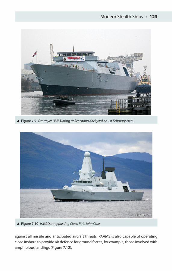
Modern Stealth Ships • 123
Figure 7.9 Destroyer HMS Daring at Scotstoun dockyard on 1st February 2006
Figure 7.10 HMS Daring passing Cloch Pt © John Crae
against all missile and anticipated aircraft threats. PAAMS is also capable of operating close inshore to provide air defence for ground forces, for example, those involved with amphibious landings (Figure 7.12).
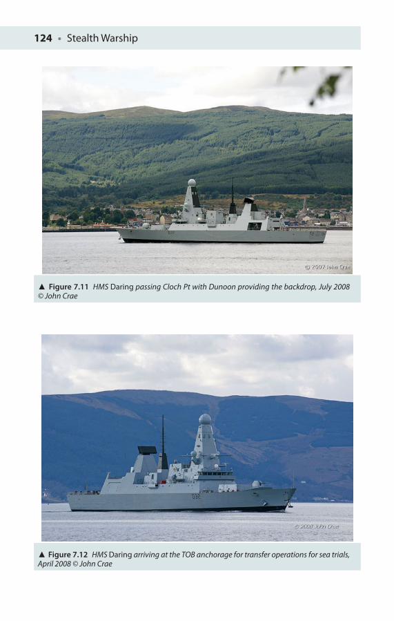
124 • Stealth Warship
Figure 7.12 HMS Daring arriving at the TOB anchorage for transfer operations for sea trials, April 2008 © John Crae
Figure 7.11 HMS Daring passing Cloch Pt with Dunoon providing the backdrop, July 2008 © John Crae
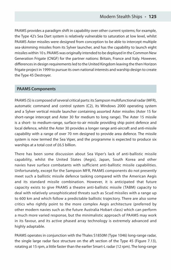
Modern Stealth Ships • 125
PAAMS provides a paradigm shift in capability over other current systems; for example, the Type 42’s Sea Dart system is relatively vulnerable to saturation at low level, whilst PAAMS Aster missiles were designed from conception to be able to intercept multiple sea-skimming missiles from its Sylver launcher, and has the capability to launch eight missiles within 10 s. PAAMS was originally intended to be deployed in the Common New Generation Frigate (CNGF) for the partner nations: Britain, France and Italy. However, diff erences in design requirements led to the United Kingdom leaving the then Horizon frigate project in 1999 to pursue its own national interests and warship design to create the Type 45 Destroyer.
PAAMS Components
PAAMS (S) is composed of several critical parts: its Sampson multifunctional radar (MFR), automatic command and control system (C2), its Windows 2000 operating system and a Sylver vertical missile launcher containing assorted Aster missiles (Aster 15 for short-range intercept and Aster 30 for medium to long range). The Aster 15 missile is a short- to medium-range, surface-to-air missile providing ship point defence and local defence, whilst the Aster 30 provides a longer range anti-aircraft and anti-missile capability with a range of over 70 nm designed to provide area defence. The missile system is now termed the Sea Viper, and the programme is expected to produce six warships at a total cost of £6.5 billion.
There has been some discussion about Sea Viper’s lack of anti-ballistic missile capability, whilst the United States (Aegis), Japan, South Korea and other navies have surface combatants with sufficient anti-ballistic missile capabilities. Unfortunately, except for the Sampson MFR, PAAMS components do not presently meet such a ballistic missile defence tasking compared with the American Aegis and its standard missile combination. However, it is anticipated that future capacity exists to give PAAMS a theatre anti-ballistic missile (TABM) capacity to deal with relatively unsophisticated threats such as Scud missiles with a range up to 600 km and which follow a predictable ballistic trajectory. There are also some critics who rightly point to the more complex Aegis architecture (preferred by other modern navies such as the future Australia Hobart class) which can perform a much more varied response, but the minimalistic approach of PAAMS may work in its favour, and its active phased array technology is extremely advanced and highly adaptable.
PAAMS operates in conjunction with the Thales S1850M (Type 1046) long-range radar, the single large radar face structure on the aft section of the Type 45 (Figure 7.13), rotating at 15 rpm, a little faster than the earlier Smart-L radar (12 rpm). The long-range
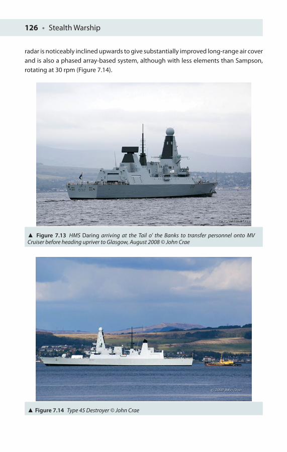
126 • Stealth Warship
radar is noticeably inclined upwards to give substantially improved long-range air cover and is also a phased array-based system, although with less elements than Sampson, rotating at 30 rpm (Figure 7.14).
Figure 7.13 HMS Daring arriving at the Tail o’ the Banks to transfer personnel onto MV Cruiser before heading upriver to Glasgow, August 2008 © John Crae
Figure 7.14 Type 45 Destroyer © John Crae
Modern Stealth Ships • 127
Agility
The ship is extremely manoeuvrable, able to turn easily a fi gure of 8 with a diameter of some three ship’s lengths and can routinely incline at signifi cant angles to the normal when in a turn. It is able to push 30 knots, and under such conditions it typically has a bow wave just forward of the gun about half way above the waterline. The Type 45, like the French La Fayette class, makes use of sliding covered panels to conduct activities such as recovery of rigid infl atable boats (RIB) from the sea with a large four-pronged, red-tipped ‘claw’. Daring has an operations room with modern state-of-the-art displays and cutting-edge technology so that each operator can sit at a number of LCD screens, typically with a blue background, onto which radar data and imagery, for example, thermal view of an attacking aircraft, can be displayed.
The Sampson design was very important in terms of its functions and the capability it brings to the platform, which in turn has a direct impact on the rest of the ship’s design. To work eff ectively, Sampson must be placed some 30 m above the waterline in order to provide the necessary radar coverage. Its size and weight determine the ship’s beam in terms of necessary stability and also its length.
The Daring class uses a new system called integrated electric propulsion (IEP). Diesel-electric engines and gas turbines generate electricity for electric motors to drive shafts. The high voltage produced is transformed down to provide power supply to the various weapon systems and the ship’s ‘hotel’ services. This power distribution architecture means electric motors can be placed much closer to the propellers and use a shorter shaft so that a mechanical gearbox is not needed [4].
Chitale [4] comments on the benefi ts of integrated full electric propulsion (IFEP): increased survivability, reduced detectability, reduced manpower, aspects the Indian Navy are keen to replicate and exploit for its own future warship designs.
From an electrical engineer’s perspective, IEP means electric motors can be operated in both directions – simply by switching voltage polarity, saving cost and requiring less maintenance, as does the absence of a gearbox! IFEP can provide a rapid rate of acceleration. In sea trials, Daring was said to have reached her top speed of 29 knots in just 70 s, reaching 31.5 knots in just over 2 min.
A recent report from the House of Commons Public Accounts Committee entitled Ministry of Defence: Type 45 Destroyer (HC 372) raised a number of concerns with the procurement process [5]. The Type 45 was procured to form the backbone of the Royal Navy’s air defence capability for the next 30 years (and potentially beyond), and it will provide a very impressive capability upgrade compared to the Type 42 Destroyers which
128 • Stealth Warship
it was designed to replace. However, the problems encountered on the project have meant that it will enter service over 2 years later than expected and £1.5 billion over budget. The UK MOD as a consequence had to extend the life of the Type 42 Destroyers for much longer as a result and at a further cost of £195 million. The problems on the Type 45 project resulted from the Department’s failure to take suffi cient account of the technical risks involved in such a complex project in its estimates of the likely costs and timescales to deliver – not, as it turns out, especially smart. The Type 45 entered service in 2009 without a single PAAMS missile having been fi red from the ship and without other equipments and capabilities to enhance the ship’s ability to conduct AAW operations, which will not be fi tted until after the ship is in service. Although the Type 45was based on 80% new technology, the Department failed to take suffi cient account of this in its assessment of technical risk. However, the percentage man-hours required to complete all the subsequent Type 45 platforms was approximately 60% that needed for Daring, the fi rst of its class. It is hoped that further lessons have been learned from this that will help in not compromise the Carrier and Future Surface Combatant (FSC or Type 26) introduction. The reduction in the number of destroyers to six (a highly controversial decision) means it will be much more challenging for the MOD to meet its policy requirement of fi ve destroyers at sea for tasking at any time.
Italian and French Destroyer Variants
Italian
The fi rst Italian Horizon-class frigate Caio Duilio (D554) was ordered in October 2000, built by Horizon Sas and Fincontieri from September 2003 to launch in October 2007 and commissioned in April 2009. The ship was named after the third-century BC Roman leader and Admiral Gauis Duilius. She has a similar displacement of 6,700 t and similar dimensions to the Type 45 Destroyer. Power is provided by four diesel generators (1.680 kW each). Propulsion is Combined Diesel or Gas (CODOG), with two gas turbine engines (20.5 MW) and two diesel engines (4.32 MW each). She can achieve 29 knots with gas turbines and 18 knots with diesel, achieving a range of 7,000 nm at 18 knots and 3,500 nm at 24 knots, and an endurance of 45 days. Caio Duilio has an E/F band Selex search radar, a 3D European multifunctional phased array radar, providing some of the functionality of Sampson (Type 1045), and essential to the C2 of PAAMS.
The platform’s integrated CMS is based on a Linux system and provides 10 redundant servers and 24 multifunction consoles (MFC): 19 located in the Primary Combat Information Centre (CIC), 3 in a remote secondary CIC, 1 in the Admiral CIC and 1 in

Modern Stealth Ships • 129
the bridge (Figure 7.15). Authorised users can access tactical data relevant to their role and common features such as the cameras, the Infra Red (IR) system view, the weapons engagement plan, status of hardware and software subsystems, fl ight orders, weather situation and so on.
The system automatically performs the control and the evaluation of each air target and suggests possible engagement with missiles, gun fi re or jammers. The system can control 24 Aster missiles simultaneously in fl ight.
Particular note is made of the ship’s response to chemical, biological, radiological and nuclear (CBRN) warfare, with a dedicated decontamination station, a series of new generation sensors for such hazards detection distributed across the ship and an external prewashing.
The long-range 3D radar used in the ship is the D-band Thales S1850M, common to the UK destroyer programme. Secondary surveillance radar and navigation radar, the I-band SPN 753(V)4, is also used. She possesses two multi-sensor target indicators and a dual-colour (two wavelength), infra-red detection and tracking system (Sagem Vampir), along with an electronic support measure (ESM) system. The platform also has a medium-frequency hull sonar, various jammers, decoys and anti-torpedo systems, besides rapid guns. She and her sister ship Andrea Doria form the Italian Doria class, whilst the French-equivalent vessels are the Forbin and the Chevalier-Paul.
Figure 7.15 The CIC of ITS Duilio

130 • Stealth Warship
France
The French meanwhile have the Forbin (D620), named after Claude Forbin-Gardanne, a seventeenth-century French Admiral – laid down in January 2004 and launched in March 2005. She was subsequently commissioned in 2008 and in service as of October 2010, and was built by DCNS and Thales group. Forbin, of the Horizon class, has a displacement of 7,050 t and draft of 5.4 m, other dimensions being the same as for the Caio Duilio. However, in addition to the PAAMS Aster missiles, she carries eight Exocet Block 3 anti-ship missiles. The hull was built in 14 sections, each section 7 m high and between 16 and 20 m long. Trials found that the CMS had some problems, delaying completion of commissioning by several months. By November 2007 these problems were overcome.
United States of America
M80 Stiletto
The M80 Stiletto is a recently built naval prototype manufactured by the M Ship Company as an operational experimental platform for the US Navy. It has an unusual catamaran (pentamaran) hull design which makes extensive use of carbon-fi bre construction for both strength and stealth. The M80 Stiletto is an American vessel designed primarily for littoral combat and shallow water roles taking its name from the Italian Stiletto – a short dagger. This 27 m-long vessel has an M-shaped hull providing a stable and fast platform for surveillance, weapons and special operations (Figure 7.16). Its shallow draft means the M80 Stiletto can operate in littoral and river environments that other naval vessels cannot operate in (due to their draught) and can even allow for amphibious assault if needed (Figure 7.17). The Stiletto is equipped with four 1,232 kW engines, modest by comparison with the power levels of the Type 45 Destroyer, but has a top speed over 50 knots and has a range of some 500 NM when fully loaded! It uses jet drives for shallow water operations and beaching and a small fl ight deck for the launch and retrieval of several UAVs. The Stiletto can set up a communications network between special inserted forces teams by launching a UAV to relay information between the team and the boat, and can send real-time images to the team on shore. The ship is 88.6 ft long, with a width of 40 ft (12 m) and a height of 18.5 ft (5.6 m), and with a surprisingly small draft of just 2.5 ft (0.8 m).
The Stiletto is the largest US naval vessel yet built using carbon-fi bre composite and advanced maritime epoxy building techniques, to yield a light but strong hull with a

Modern Stealth Ships • 131
very low RCS to avoid radar detection. The M80’s hull is unusually wide to capture the vessel’s bow wave and redirect the wave energy under the hull. The Stiletto’s double-M hull enables the craft to achieve as smooth a ride as possible in rough seas at high speed, critical for Navy SEALS and Special Operations Forces.
Text by the US Navy: ‘Sailors assigned to Naval Special Clearance Team One (NSCT-1) prepare to enter the well deck aboard experimental boat ship Stiletto’.
Figure 7.16 The crew of the experimental boat ship Stiletto readies the ship as it prepares to launch a UAV during Exercise Howler. Stiletto is being tested for its usefulness in littoral combat warfare and interoperable environments.
Figure 7.17 M80 Stiletto during a NAVY SEALs training
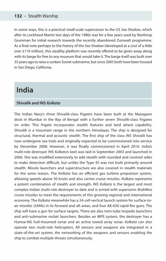
132 • Stealth Warship
In some ways, this is a practical small-scale supercessor to the US Sea Shadow, which after its Lockheed Martin test days of the 1980s was for a few years used by Northrop Grumman for initial research towards the recently abandoned Zumwalt programme. As a fi nal note perhaps to the history of the Sea Shadow (developed at a cost of a little over £110 million), this stealthy platform was recently off ered to be given away along with its barge for free to any museum that would take it. The barge itself was built over 35 years ago to raise a sunken Soviet submarine, but since 2005 both have been housed in San Diego, California.
India
Shivalik and INS Kolkata
The Indian Navy’s three Shivalik-class frigates have been built at the Mazagaon dock in Mumbai in the Bay of Bengal with a further seven Shivalik-class frigates on order. This frigate incorporates stealth features and land attack capability. Shivalik is a mountain range in the northern Himalayas. The ship is designed for structural, thermal and acoustic stealth. The fi rst ship of the class INS Shivalik has now undergone sea trials and originally expected to be commissioned into service by December 2008. However, it was fi nally commissioned in April 2010. India’s multi-role destroyer INS Kolkata’s keel was laid in September 2003 and launched in 2006. She was modifi ed extensively to add stealth with rounded and covered sides to make detection diffi cult, but unlike the Type 45 was not built primarily around stealth. Missile launchers and superstructure are also covered in stealth materials for the same reason. The Kolkata has an effi cient gas turbine propulsion system, allowing speeds above 30 knots and also carries cruise missiles. Kolkata represents a potent combination of stealth and strength. INS Kolkata is the largest and most complex Indian multi-role destroyer to date and is armed with supersonic BrahMos cruise missiles to meet the requirements of this growing regional and international economy. The Kolkata meanwhile has a 24-cell vertical launch system for surface-to-air missiles (SAMs) in its forward and aft areas, and four AK-630 rapid-fi re guns. The ship will have a gun for surface targets. There are also twin-tube torpedo launchers and anti-submarine rocket launchers. Besides an MFR system, the destroyer has a Humsa-NG hull-mounted sonar and an active towed array sonar. Kolkata can also operate two multi-role helicopters. All sensors and weapons are integrated in a state-of-the-art system, the networking of the weapons and sensors enabling the ship to combat multiple threats simultaneously.
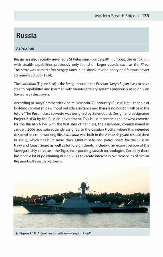
Modern Stealth Ships • 133
Russia
Astrakhan
Russia has also recently unveiled a St Petersburg-built stealth gunboat, the Astrakhan, with stealth capabilities previously only found on larger vessels such as the Kirov. The Kirov was named after Sergey Kirov, a Bolshevik revolutionary and famous Soviet communist (1886–1934).
The Astrakhan (Figure 7.18) is the fi rst gunboat in the Russian Navy’s Buyan class to have stealth capabilities and is armed with various artillery systems previously used only on Soviet navy destroyers.
According to Navy Commander Vladimir Masorin, ‘Our country (Russia) is still capable of building combat ships without outside assistance and there is no doubt it will be in the future.’ The Buyan-class corvette was designed by Zelenodolsk Design and designated Project 21630 by the Russian government. This build represents the newest corvette for the Russian Navy, with the fi rst ship of her class, the Astrakhan, commissioned in January 2006 and subsequently assigned to the Caspian Flotilla, where it is intended to spend its entire working life. Astrakhan was built in the Almaz shipyard (established in 1901), which has built more than 1,000 missile and patrol boats for the Russian Navy and Coast Guard as well as for foreign clients, including an export version of the Stevegushchiy corvette – the Tiger, incorporating stealth technologies. Certainly there has been a lot of positioning during 2011 to create interest in overseas sales of similar Russian-built stealth platforms.
Figure 7.18 Astrakhan corvette from Caspian Flotilla
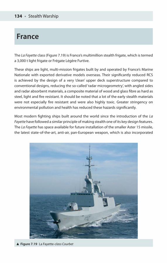
134 • Stealth Warship
France
The La Fayette class (Figure 7.19) is France’s multimillion stealth frigate, which is termed a 3,000 t light frigate or Frégate Légère Furtive.
These ships are light, multi-mission frigates built by and operated by France’s Marine Nationale with exported derivative models overseas. Their signifi cantly reduced RCS is achieved by the design of a very ‘clean’ upper deck superstructure compared to conventional designs, reducing the so-called ‘radar microgeometry’, with angled sides and radar absorbent materials, a composite material of wood and glass fi bre as hard as steel, light and fi re resistant. It should be noted that a lot of the early stealth materials were not especially fi re resistant and were also highly toxic. Greater stringency on environmental pollution and health has reduced these hazards signifi cantly.
Most modern fi ghting ships built around the world since the introduction of the La Fayette have followed a similar principle of making stealth one of its key design features. The La Fayette has space available for future installation of the smaller Aster 15 missile, the latest state-of-the-art, anti-air, pan-European weapon, which is also incorporated
Figure 7.19 La Fayette-class Courbet
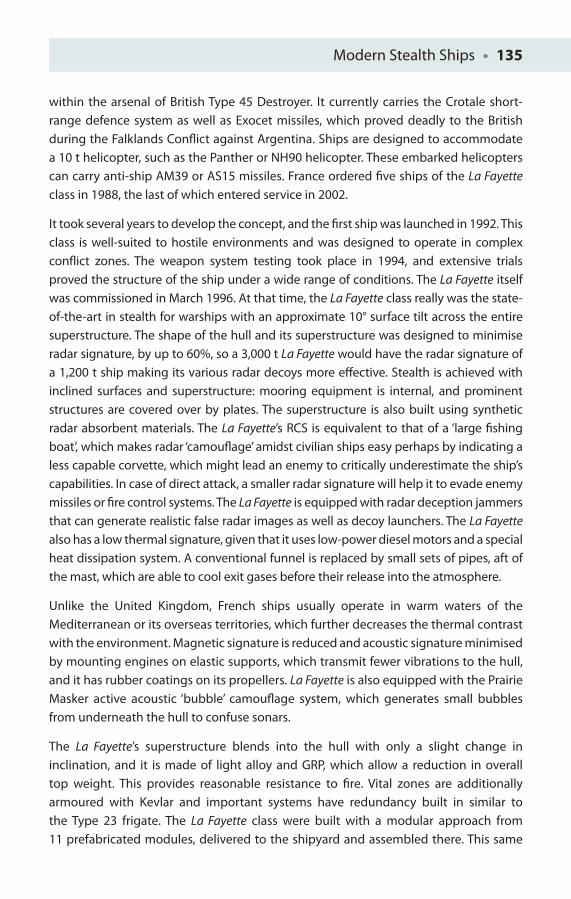
Modern Stealth Ships • 135
within the arsenal of British Type 45 Destroyer. It currently carries the Crotale short-range defence system as well as Exocet missiles, which proved deadly to the British during the Falklands Confl ict against Argentina. Ships are designed to accommodate a 10 t helicopter, such as the Panther or NH90 helicopter. These embarked helicopters can carry anti-ship AM39 or AS15 missiles. France ordered fi ve ships of the La Fayette class in 1988, the last of which entered service in 2002.
It took several years to develop the concept, and the fi rst ship was launched in 1992. This class is well-suited to hostile environments and was designed to operate in complex confl ict zones. The weapon system testing took place in 1994, and extensive trials proved the structure of the ship under a wide range of conditions. The La Fayette itself was commissioned in March 1996. At that time, the La Fayette class really was the state-of-the-art in stealth for warships with an approximate 10° surface tilt across the entire superstructure. The shape of the hull and its superstructure was designed to minimise radar signature, by up to 60%, so a 3,000 t La Fayette would have the radar signature of a 1,200 t ship making its various radar decoys more eff ective. Stealth is achieved with inclined surfaces and superstructure: mooring equipment is internal, and prominent structures are covered over by plates. The superstructure is also built using synthetic radar absorbent materials. The La Fayette’s RCS is equivalent to that of a ‘large fi shing boat’, which makes radar ‘camoufl age’ amidst civilian ships easy perhaps by indicating a less capable corvette, which might lead an enemy to critically underestimate the ship’s capabilities. In case of direct attack, a smaller radar signature will help it to evade enemy missiles or fi re control systems. The La Fayette is equipped with radar deception jammers that can generate realistic false radar images as well as decoy launchers. The La Fayette also has a low thermal signature, given that it uses low-power diesel motors and a special heat dissipation system. A conventional funnel is replaced by small sets of pipes, aft of the mast, which are able to cool exit gases before their release into the atmosphere.
Unlike the United Kingdom, French ships usually operate in warm waters of the Mediterranean or its overseas territories, which further decreases the thermal contrast with the environment. Magnetic signature is reduced and acoustic signature minimised by mounting engines on elastic supports, which transmit fewer vibrations to the hull, and it has rubber coatings on its propellers. La Fayette is also equipped with the Prairie Masker active acoustic ‘bubble’ camoufl age system, which generates small bubbles from underneath the hull to confuse sonars.
The La Fayette’s superstructure ble nds into the hull with only a slight change in inclination, and it is made of light alloy and GRP, which allow a reduction in overall top weight. This provides reasonable resistance to fi re. Vital zones are additionally armoured with Kevlar and important systems have redundancy built in similar to the Type 23 frigate. The La Fayette class were built with a modular approach from 11 prefabricated modules, delivered to the shipyard and assembled there. This same
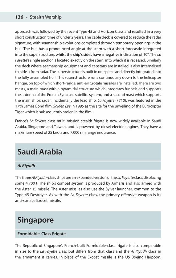
136 • Stealth Warship
approach was followed by the recent Type 45 and Horizon Class and resulted in a very short construction time of under 2 years. The cable deck is covered to reduce the radar signature, with seamanship evolutions completed through temporary openings in the hull. The hull has a pronounced angle at the stern with a short forecastle integrated into the superstructure, whilst the ship's sides have a negative inclination of 10°. The La Fayette’s single anchor is located exactly on the stern, into which it is recessed. Similarly the deck where seamanship equipment and capstans are installed is also internalised to hide it from radar. The superstructure is built in one piece and directly integrated into the fully assembled hull. This superstructure runs continuously down to the helicopter hangar, on top of which short-range, anti-air Crotale missiles are installed. There are two masts, a main mast with a pyramidal structure which integrates funnels and supports the antenna of the French Syracuse satellite system, and a second mast which supports the main ship’s radar. Incidentally the lead ship, La Fayette (F71 0), was featured in the 17th James Bond fi lm Golden Eye in 1995 as the site for the unveiling of the Eurocopter Tiger which is subsequently stolen in the fi lm.
France’s La Fayette-class multi-mission stealth frigate is now widely available in Saudi Arabia, Singapore and Taiwan, and is powered by diesel-electric engines. They have a maximum speed of 25 knots and 7,000 nm range endurance.
Saudi Arabia
Al Riyadh
The three Al Riyadh-class ships are an expanded version of the La Fayette class, displacing some 4,700 t. The ship’s combat system is produced by Armaris and also armed with the Aster 15 missile. The Aster missiles also use the Sylver launcher, common to the Type 45 Destroyer. As with the La Fayette class, the primary off ensive weapon is its anti-surface Exocet missile.
Singapore
Formidable-Class Frigate
The Republic of Singapore’s French-built Formidable-class frigate is also comparable in size to the La Fayette class but diff ers from that class and the Al Riyadh class in the armament it carries. In place of the Exocet missile is the US Boeing Harpoon.
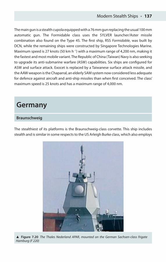
Modern Stealth Ships • 137
The main gun is a stealth cupola equipped with a 76 mm gun replacing the usual 100 mmautomatic gun. The Formidable class uses the SYLVER launcher/Aster missile combination also found on the Type 45. The fi rst ship, RSS Formidable, was built by DCN, while the remaining ships were constructed by Singapore Technologies Marine. Maximum speed is 27 knots (50 km h−1) with a maximum range of 4,200 nm, making it the fastest and most mobile variant. The Republic of China (Taiwan) Navy is also seeking to upgrade its anti-submarine warfare (ASW) capabilities. Six ships are confi gured for ASW and surface attack. Exocet is replaced by a Taiwanese surface attack missile, and the AAW weapon is the Chaparral, an elderly SAM system now considered less adequate for defence against aircraft and anti-ship missiles than when fi rst conceived. The class’ maximum speed is 25 knots and has a maximum range of 4,000 nm.
Germa n y
Braunschweig
The stealthiest of its platforms is the Braunschweig-class corvette. This ship includes stealth and is similar in some respects to the US Arleigh Burke class, which also employs
Figure 7.20 The Thales Nederland APAR, mounted on the German Sachsen-class frigate Hamburg (F 220)
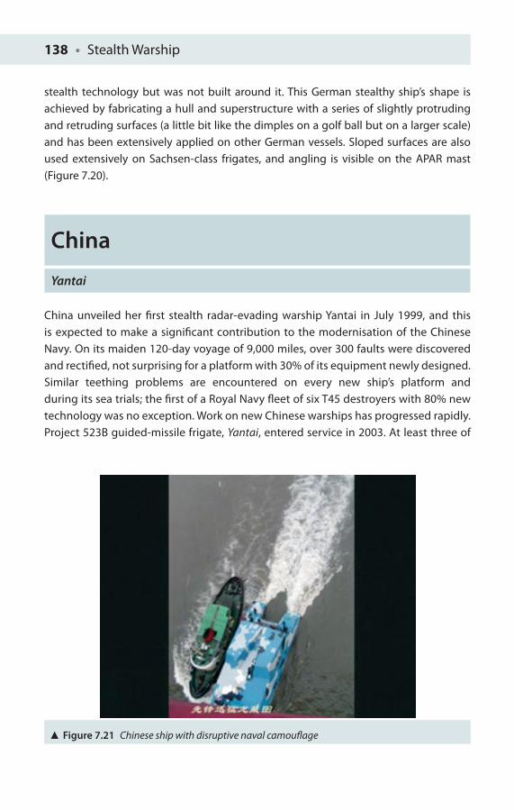
138 • Stealth Warship
stealth technology but was not built around it. This German stealthy ship’s shape is achieved by fabricating a hull and superstructure with a series of slightly protruding and retruding surfaces (a little bit like the dimples on a golf ball but on a larger scale) and has been extensively applied on other German vessels. Sloped surfaces are also used extensively on Sachsen-class frigates, and angling is visible on the APAR mast (Figure 7.20).
China
Yantai
China unveiled her fi rst stealth radar-evading warship Yantai in July 1999, and this is expected to make a signifi cant contribution to the modernisation of the Chinese Navy. On its maiden 120-day voyage of 9,000 miles, over 300 faults were discovered and rectifi ed, not surprising for a platform with 30% of its equipment newly designed. Similar teething problems are encountered on every new ship’s platform and during its sea trials; the fi rst of a Royal Navy fl eet of six T45 destroyers with 80% new technology was no exception. Work on new Chinese warships has progressed rapidly. Project 523B guided-missile frigate, Yantai, entered service in 2003. At least three of
Figure 7.21 Chinese ship with disruptive naval camoufl age
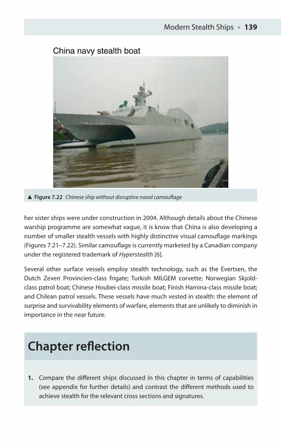
Modern Stealth Ships • 139
her sister ships were under construction in 2004. Although details about the Chinese warship programme are somewhat vague, it is know that China is also developing a number of smaller stealth vessels with highly distinctive visual camoufl age markings (Figures 7.21–7.22). Similar camoufl age is currently marketed by a Canadian company under the registered trademark of Hyperstealth [6].
Several other surface vessels employ stealth technology, such as the Evertsen, the Dutch Zeven Provincien-class frigate; Turkish MILGEM corvette; Norwegian Skjold-class patrol boat; Chinese Houbei-class missile boat; Finish Hamina-class missile boat; and Chilean patrol vessels. These vessels have much vested in stealth: the element of surprise and survivability elements of warfare, elements that are unlikely to diminish in importance in the near future.
Chapter refl ection
Figure 7.22 Chinese ship without disruptive naval camoufl age
1. Compare the diff erent ships discussed in this chapter in terms of capabilities (see appendix for further details) and contrast the diff erent methods used to achieve stealth for the relevant cross sections and signatures.
140 • Stealth Warship
References
1. http://www.kockums.se/.
2. Phillips, LD (2011), ‘The Royal Navy’s Type 45 story: A case study’, Chapter 3, in A Salo, J Keisler and A Morton (eds), Portfolio Decision Analysis: Improved Methods for Resource Allocation, International Series in Operations Research and Management Science 162, DOI 10.1007/978-1-4419-9943-6, New York: Springer Science and Business Media, LLC.
3. Comptroller and Auditor General (2009), Ministry of Defence: Providing Anti-Air Warfare Capability: The Type 45 Destroyer: Report. HC (2008–09), vol. 295. London: The Stationery Offi ce.
4. Chitale, Captain SS (2010), ‘Integrated full electric propulsion’, Journal of the Institution of Engineers (India), 90: 18–22.
5. House of Commons Public Accounts Committee. (2009). Ministry of Defence: Type 45 Destroyer, Thirtieth Report of Session: Report. HC (2008–09), vol. 372. London: The Stationery Offi ce Limited.
6. www.hyperstealth.com.
FUTURE NAVAL STEALTH
PLATFORMS
8
It follows then as certain as that night succeeds the day, that without a decisive
naval force we can do nothing defi nitive
President George Washington, 1781
The book so far has examined the history of stealth and the key aspects of stealth technology, and reviewed the current generation of stealth vessels and prototype vessels. This last chapter is more difficult to finalise as it considers ships in the initial planning stage and those in early build, as well as one recently abandoned stealth vessel (which will feed into future US surface platforms), and various ideas that may be incorporated into other future surface combatant (FSC) platforms, particularly those concepts drawn from developments in the aviation industry. Consequently this chapter is in some respects the most interesting and yet may be the furthest from the mark when considered in reflection in 10 years time! From an author’s viewpoint, the ‘twists and turns’ of changes in government and a changing background of costs is apparent in discussions of the chosen aircraft for the Queen Elizabeth-class aircraft carrier, requiring several rewrites – the last being May 2012.
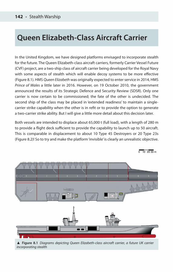
142 • Stealth Warship
Figure 8.1 Diagrams depicting Queen Elizabeth-class aircraft carrier, a future UK carrier incorporating stealth
Queen Elizabeth-Class Aircraft Carrier
In the United Kingdom, we have designed platforms envisaged to incorporate stealth for the future. The Queen Elizabeth-class aircraft carriers, formerly Carrier Vessel Future (CVF) project, are a two-ship class of aircraft carrier being developed for the Royal Navy with some aspects of stealth which will enable decoy systems to be more eff ective (Figure 8.1). HMS Queen Elizabeth was originally expected to enter service in 2014, HMS Prince of Wales a little later in 2016. However, on 19 October 2010, the government announced the results of its Strategic Defence and Security Review (SDSR). Only one carrier is now certain to be commissioned; the fate of the other is undecided. The second ship of the class may be placed in ‘extended readiness’ to maintain a single-carrier strike capability when the other is in refi t or to provide the option to generate a two-carrier strike ability. But I will give a little more detail about this decision later.
Both vessels are intended to displace about 65,000 t (full load), with a length of 280 m to provide a fl ight deck suffi cient to provide the capability to launch up to 50 aircraft. This is comparable in displacement to about 10 Type 45 Destroyers or 20 Type 23s (Figure 8.2)! So to try and make the platform ‘invisible’ is clearly an unrealistic objective.
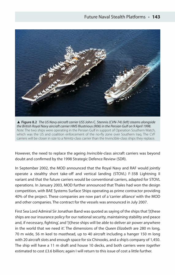
Future Naval Stealth Platforms • 143
However, the need to replace the ageing Invincible-class aircraft carriers was beyond doubt and confi rmed by the 1998 Strategic Defence Review (SDR).
In September 2002, the MOD announced that the Royal Navy and RAF would jointly operate a stealthy short take-off and vertical landing (STOVL) F-35B Lightning II variant and that the future carriers would be conventional carriers, adapted for STOVL operations. In January 2003, MOD further announced that Thales had won the design competition, with BAE Systems Surface Ships operating as prime contractor providing 40% of the project. These companies are now part of a ‘carrier alliance’ with the MOD and other companies. The contract for the vessels was announced in July 2007.
First Sea Lord Admiral Sir Jonathan Band was quoted as saying of the ships that ‘[t]hese ships are our insurance policy for our national security, maintaining stability and peace and, if necessary, fi ghting’, and ‘[t]hese ships will be able to deliver air power anywhere in the world that we need it’. The dimensions of the Queen Elizabeth are 280 m long, 70 m wide, 56 m keel to masthead, up to 40 aircraft including a hanger 150 m long with 20 aircraft slots and enough space for six Chinooks, and a ship’s company of 1,450. The ship will have a 11 m draft and house 10 decks, and both carriers were together estimated to cost £3.6 billion; again I will return to this issue of cost a little further.
Figure 8.2 The US Navy aircraft carrier USS John C. Stennis (CVN-74) (left) steams alongside the British Royal Navy aircraft carrier HMS Illustrious (R06) in the Persian Gulf on 9 April 1998.Note: The two ships were operating in the Persian Gulf in support of Operation Southern Watch, which was the US and coalition enforcement of the no-fl y zone over Southern Iraq. The CVF carriers will be closer in size to a Nimitz-class carrier than the Invincible-class ships they replace.
144 • Stealth Warship
A Brief History of the Build So Far
On 25 January 1999, six companies were invited to tender for the project’s assessment phase – British Aerospace, Boeing, Lockheed Martin, Marconi Electronic Systems, Thomson-CSF and Raytheon. In November 1999, the UK MOD awarded detailed assessment studies to two consortia, one led by BAE Systems and the other by the Thales Group. The brief required multiple designs from each consortium with anticipated air groups of up to 40 Future Joint Combat Aircraft (FJCA). Contracts were split into two phases, the fi rst a £5.9 million phase for design assessment, forming part of the aircraft selection, whist the second £23.5 million phase involving ‘risk reduction on the preferred carrier design option’.
In January 2001, the United Kingdom signed a Memorandum of Understanding with the US Department of Defense for full participation in the JSF programme, confi rming the JSF as the FJCA. In September 2002, the STOVL F-35B Lightning II variant was selected for STOVL operations. The carriers are expected to remain in service for up to 50 years, and planned to be ‘future proof’, allowing them to operate a second generation of aircraft beyond the F-35.
The contract for the vessels was announced in July 2007 by the Secretary of State for Defence, ending delays over costs and naval shipyard restructuring. The cost was estimated initially as £3.5–3.6 billion. Contracts were signed in July 2008 after the creation of BVT Surface Fleet through the merger of BAE Systems Surface Fleet Solutions and VT Group’s VT Shipbuilding – a requirement set by the UK government.
In October 2010, the UK government announced the results of the SDSR which stated that only one carrier would be commissioned. This has several implications for UK carrier strike capability and was the subject of a House of Commons Committee of Public Accounts report [1]. Oral evidence provided by Ursula Brenna, Permanent Under-Secretary of MOD to Mr Richard Bacon, in July 2011 confi rmed the view that originally the MOD should have had two aircraft carriers for just over £3.6 billion. However, the United Kingdom will now only get one useable aircraft carrier for nearly twice that fi gure (£6.24 billion). There are also further total cost uncertainties as there is some other equipment included in the carrier design which needs to be fully quantifi ed. This stands against the 1998 SDR, which was then committed to replace the three existing Invincible-class aircraft carriers with two larger more versatile carriers. The current projection is the United Kingdom will have no fi xed-wing carrier aircraft capability for 2012–2020, and is reduced to a single operational carrier with signifi cantly reduced
Future Naval Stealth Platforms • 145
availability at sea when carrier strike capability is reintroduced in 2020. Certainly the carrier variant will be more capable with greater operational range (10,000 NM) and the ability to carry a heavier payload than previously. However, it will require installation of catapults and arrestor gear to assist aircraft in both take-off and land. The proposed technology has yet to be tested, and the version the United Kingdom intends to buy will be unique to Britain – a key risk element.
The costs of converting the carrier for use with the carrier variant aircraft (the STOVL variant of the JSF) would not be known until late 2012 at the earliest. The decision of the fi nancial benefi t from converting to the carrier variant aircraft, against what it would cost to convert the aircraft carriers (providing a large potential saving by moving to this variant aircraft), appears to have been made in advance of any defi nitive costing as the accurate fi gure will not be available until after the 18-month conversion development phase costs and risks report is submitted! However, initial assessment seemed to support this move and it should be added that available manpower is also a factor in the decision to provide only one operational aircraft carrier.
To start with, there should be six operational fi xed-wing aircraft on the carrier at its inception in 2020, as the fi rst half of the fi rst squadron of 12. At this stage, and after it, the fi gure of aircraft is uncertain. Certainly the MOD had stated a requirement for the carrier strike capability to be able to generate daily sortie rates of 72 with 36 fast jets embarked. As a result of the SDSR decision, the sortie rate will be reduced to 20, which leads to the question of whether with fewer planes the carriers will be able to fulfi l their role as outlined for them in the National Security Strategy. Proportionally, a daily sortie rate of 20 could be delivered by only 10 FJCA, not even a full squadron. The STOVL aircraft is also more complicated than the more conventional aircraft. It has an extra engine and is trying to do complex things, such as a STOVL. It also has a smaller bomb bay, which may create diffi culties for existing sized weapons.
On entering service, the Queen Elizabeth is anticipated to achieve a top speed of 25 knots, with power supplied by two Rolls-Royce Marine Trent MT30 36 MW gas turbine generators and four tried and tested Wärtsilä diesel generator sets (two 9 MW and two 11 MW sets). These generators are the largest ever supplied to the Royal Navy, which feed the low-voltage system that supplies the tandem electric propulsion motors driving the twin fi xed-pitch propeller shafts. Interestingly a non-propulsor technology has been chosen in spite of this producing less acoustic noise.
The fl ight deck is equivalent to three football pitches, with two small islands instead of a traditional large, single island. The forward island will control the ship’s functions, while the aft island is for air traffi c control (ATC). Beneath the fl ight deck are a further nine decks, with a hangar deck measuring 509 by 109.9 ft and height between 22 and 33 ft,
146 • Stealth Warship
large enough to accommodate 20 fi xed- and rotary-wing aircraft. To transfer aircraft from the hangar to the fl ight deck, the ships will have two large lifts, each capable of lifting two F-35-sized aircraft from the hangar to the fl ight deck in 1 min.
Radar and Weapons Systems
The ship’s radars will be the BAE Systems Type 1046 long-range radar, as fi tted to the Type 45, for wide area search, and the BAE Systems Artisan 3D maritime medium-range radar and a navigation radar. The BAE claims the Type 1046 has a fully automatic detection and track initiation that can track up to 1,000 air targets at a range of 400 km, whilst Artisan is reputed to be able to track targets the size of a shell over 12.5 miles away.
Munitions and ammunition handling is achieved with a highly mechanised weapons handling system (HMWHS). This is the Royal Navy’s fi rst naval application of this common land-based warehouse system. The HMWHS moves palleted munitions from magazines and weapon preparation areas, along set tracks and via lifts (forward and aft, port and starboard). Tracks can carry a pallet to magazines, the hangar, weapons preparation areas and the fl ight deck. Magazines will be fully automated for the fi rst time, pallet movement is controlled instead from a central location; men are only needed when munitions are initially stored or prepared, which speeds the delivery and reduces the needed crew size. However, the ship’s only self-defence is the Phalanx CIWS to counter airborne threats, with mini-guns and 30 mm cannons to counter seaborne threats.
Embarked Fleet Air Arm?
The carrier is expected to carry 40 aircraft, for example, 35 F-35s and 5 helicopters, although the fi nal number is uncertain. In my view, the ill-timed forced retirement of the Harrier GR7/9 in 2010 (which was done rather than retiring the Tornado, an aircraft still required for its ground attack role which the Typhoon has yet to develop fully) leaves the Royal Navy and RAF with a lamentable lack in current carrier-capable, fi xed-wing aircraft availability. This decision has created an avoidable temporary capability shortfall.
Both ships were originally intended to carry the STOVL version, the F-35B. In October 2010, British Prime Minister David Cameron announced that the United Kingdom would

Future Naval Stealth Platforms • 147
change their order to the F-35C carrier variant, and both platforms would be modifi ed to use a suitable CATOBAR system for launch and landing aircraft, so the cheaper F-35C variant with its greater range can carry a larger and more diverse payloads than the F-35B. However, on May 2012, Defence Secretary Philip Hammond announced the F-35C now had ‘developmental problems’ and it would now be cheaper to order F-35B jump jets as originally planned! Unfortunately, this reversal will cost about £100 million. F-35C delays would have meant aircraft would enter service from 2023 onwards – 3 years later than planned. Financially, scrapping the CATOBAR system does put two possible carriers into operational service. The estimated cost of the CATOBAR system had increased from £950 million to £2 billion – and rising. Putting the F-35B STOVL back raises individual aircraft cost from £59.9 to £65.5 million, but without any carrier adaptation costs. The government was criticised for this decision, but it makes fi nancial sense in spite of being a real ‘U-turn’ and should be valued for restoring two carrier platforms. As I previously stated, the electromagnetic launch system is an untested UK technology, and it is wiser to go for a ‘tried and tested’ technology at this stage rather than after an expensive £2 billion conversion failure!
The remaining factor to consider is the availability of aircrew. With the Harrier scrapped (and sold to the Americans who quickly bought them all up), and the view that STOVL skills were no longer needed, most of the highly skilled Harrier pilots were made redundant, with a few retained training to fl y the F-18. It is lamentably easier to build a platform than to prevent skills fade or to hone those skills in the fi rst place.
Carrier Construction
The carrier build is being undertaken by four companies across seven shipyards, with block integration and assembly at Rosyth by BAE Systems Surface Ships: Govan (lower blocks 3 and 4), Scotstoun (aft island) and Portsmouth (lower block 2 and forward island); Babcock Mari: Rosyth (sponsons, mast and centre blocks 5 and 6) and Appledore (lower block 1); A&P Group: Hebburn (centre block 3); and Cammell Laird: Birkenhead (centre blocks 2 and 4). In December 2007, eight diesel engines and electricity generators, four for each ship, were ordered from Wärtsilä. In March 2008, contracts for 80,000 t of steel were placed with Corus Group (value £65 million). Other contracts included £4 million for aviation fuel systems, £3 million for fi bre-optic cable and £1 million for reverse osmosis equipment, providing 500 t of fresh water daily. In April 2008, a contract for manufacture of the specialist F-35C aircraft lifts (£13 million) was awarded to MacTaggart Scott of Loanhead, Scotland.
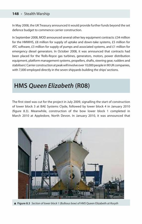
148 • Stealth Warship
In May 2008, the UK Treasury announced it would provide further funds beyond the set defence budget to commence carrier construction.
In September 2008, MOD announced several other key equipment contracts: £34 million for the HMWHS, £8 million for supply of uptake and down-take systems, £5 million for ATC software, £3 million for supply of pumps and associated systems, and £1 million for emergency diesel generators. In October 2008, it was announced that contracts had been placed for the ‘Rolls-Royce gas turbines, generators, motors, power distribution equipment, platform management systems, propellers, shafts, steering gear, rudders and stabilisers’. Carrier construction at peak will involve over 10,000 people in 90 UK companies, with 7,000 employed directly in the seven shipyards building the ships’ sections.
HMS Queen Elizabeth (R08)
The fi rst steel was cut for the project in July 2009, signalling the start of construction of lower block 3 at BAE Systems Clyde, followed by lower block 4 in January 2010 (fi gure 8.3). Meanwhile, construction of the bow lower block 1 completed in March 2010 at Appledore, North Devon. In January 2010, it was announced that
Figure 8.3 Section of lower block 1 (Bulbous bow) of HMS Queen Elizabeth at Rosyth
Future Naval Stealth Platforms • 149
Cammell Laird has also secured a £44 million contract to build the carriers’ fl ight decks. In August 2011, the 8,000 t lower block 3 of HMS Queen Elizabeth left BAE’s Govan shipyard on a large barge to travel 600 miles around the north coast of Scotland, arriving in Rosyth on the 20th August.
In November 2011, it was announced that the Queen Elizabeth would not be fi nished in a CATOBAR confi guration, in spite of earlier assurances, which has considerable consequences for F-35C operations. The First Sea Lord Admiral Stanhope said, ‘Current navy assumptions will see the second-in-class aircraft carrier fi tted with catapults and arrestor wire ready to operate the F-35C Joint Strike Fighter carrier variant in 2020, but the fate of HMS Queen Elizabeth, which will launch fi rst and be used to train crews in handling HMS Prince of Wales, is less certain’ [2]. Training of embarked fl ight crew will be aff ected by this decision. The May 2012 Defence Secretary announcement will see these shortfalls and several important operational issues back on the ‘road to recovery’.
Under present plans, HMS Queen Elizabeth will enter service in 2016. Construction on the second carrier, HMS Prince of Wales, began in May 2011 when then Defence Secretary Liam Fox cut the fi rst steel. In November 2011, the First Sea Lord Admiral Stanhope confi rmed that the Prince of Wales will be fi tted to a CATOBAR confi guration, a conversion which is expected to increase the total cost, potentially to over £6.2 billion. HMS Prince of Wales, entering service in 2018, would only be the second ship in the world fi tted with the American electromagnetic aircraft launch system (EMALS). I am not holding my breath that there will be no future changes, but it is very unlikely to be another last minute ‘U-turn’ on this particular issue of the aircraft variant!
UK FSC or Type 26 Frigate
The Future Surface Combatant is a generic expression describing developments in several navies worldwide. The Royal Swedish Navy, for example, with its current Visby-class corvette (one might say a littoral surface combatant (LSC) of the future already here today), is even now thinking ahead to the mid-twenty-fi rst century with the intent to build modular multifunction corvettes which can operate in the littoral zone and potentially outside of it on a global scale [3]. The US Navy is also looking to the future with its own littoral combat ship (LCS) seeking scaled, modular war-fi ghting capability with a 40-knot spring speed and shallow draft [4]. Lockheed
150 • Stealth Warship
Martin has also undertaken preliminary design work on an LCS proposed to the Israeli Navy (known as the LCS-I), with additional interest drawn from Saudi Arabia. However, Israel is now believed to favour its own LCS development in Israel, whilst French interest lies with its FutuRe European Multi-Mission (FREMM) frigates [5]. Meanwhile the British are looking to the Type 26, or Global Combat Ship (GCS), as its FSC [6, 7].
The Type 26 frigate or GCS is a ship programme underway by the Ministry of Defence. The fi rst Type 26 frigate is expected to enter service after 2020 to replace the 13 Type 23 frigates still in service. In March 2010, the BAE Systems Surface Ships was awarded a 4-year contract to develop the Type 26 variant of the GCS. The 2010 SDSR reaffi rmed the UK government’s commitment to the FSC, stating that ‘[a]s soon as possible after 2020 the Type 23 will be replaced by Type 26 frigates, designed to be easily adapted to change roles and capabilities depending on the strategic circumstances’ [8]. The platform will incorporate existing available stealth technology but is unlikely to include many new stealth concepts or new technologies as the priority is to produce as many versatile FSCs as cheaply as possible.
Plans for an FSC escort vessel to replace the Royal Navy’s ageing Type 22 and Type 23 frigates started in 1998 with the RV Triton, to see if a trimaran design was practical for such a large and complex vessel. However, by early 2000, the Royal Navy favoured a more conventional design. In March 2005, plans were released for a two-class solution, a cheaper ‘medium-sized vessel derivative’ and a more capable ‘versatile surface combatant’ [9].
In 2006, the MOD started a Sustained Surface Combatant Capability (S2C2) programme to explore effi ciencies and synergies between the FSC and the need for updated minesweepers, patrol ships and survey ships. By early 2007, this generated three requirements: C1, C2 and C3. C1 was to be an ASW platform, C2 a general purpose platform and C3 a Global Corvette replacing a larger number of smaller vessels.
In early 2010, the C3 variant was dropped in favour of the Mine Countermeasures Hydrographic and Patrol Capability (MHPC) programme to update the mine countermeasures vessels (MCV) capabilities currently provided by RN Sandown-class minesweepers (and also by the US Navy’s Avenger class). The FSC concept was brought forward in the 2008 budget, at the expense of two Type 45 destroyers. In 2009, the BAE Systems received a contract to design the C1 and C2 frigates with a planned 25-year lifespan.
In March 2010, the BAE Systems was given a 4-year, £127 million contract to design the Type 26 GCS (formerly the FSC C1). It was confi rmed that the fi rst of these Type 26 frigates is expected to be delivered to the Royal Navy by 2020. The SDSR then decided to merge the remaining two FSC classes into the Type 26 GCS. The Type 26 will combine
Future Naval Stealth Platforms • 151
advantages of both variants into a versatile ship, designed to readily change roles and capabilities depending on the strategic circumstances – at least this is the intent.
As a result of the SDSR, the Royal Navy’s escort fl eet is left with a modest 19 destroyers and frigates (6 Type 45 destroyers and 13 Type 23 frigates) and may struggle to meet anticipated (apart from unanticipated) requirements. Unlike the original FSC, the GCS will have only one hull design. The current design has a length of 148 m, beam of 19 m, top speed of at least 26 knots (48 km hr−1) and a crew of 130 with room for 36 embarked troops. It will have 60 days endurance and a range of 7,000 miles at 15 knots (28 km hr−1).
Weapons and Systems
These ships will use the Artisan 3D search radar, Sonar 2087 (towed array sonar) and Sea Ceptor, common anti-air modular missile (CAMM) air defence missiles launched via a vertical launch seawolf (VLS). In addition, like the Type 23 frigates they replace, the Type 26 frigate will be equipped with a torpedo launching system with existing or next-generation acoustic homing torpedoes. It is expected that the Type 26 frigate will be equipped from inception with two quad, anti-ship missile launchers (e.g. eight harpoon missiles), unlike the Type 45.
The Type 26 will be fi tted-out with guns of various calibres. Primarily it is expected that the main gun will consist of either the ‘127 mm, medium-calibre gun’ or the BAE Systems’ 4.5 in. Mark 8 naval gun. In addition, smaller guns will be included.
Modular and Flexible
The GCS is designed to be modular and fl exible to enhance versatility across its full operational range: maritime security, counter piracy and terrorism as well as humanitarian and disaster relief operations. In the stern, a mission bay with a ramp allows RIB deployment and unmanned surface vehicles or towed array sonar storage. The well deck at the back permits unmanned underwater vehicle (UUV) launch and recovery. Aircraft similar in size to the Boeing Chinook can also fl y from the large fl ight deck, and the hangar can accommodate either Merlin or Wildcat helicopters. The fl ight deck and hanger can additionally accommodate UAVs.
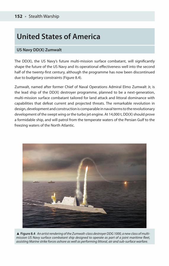
152 • Stealth Warship
United States of America
US Navy DD(X) Zumwalt
The DD(X), the US Navy’s future multi-mission surface combatant, will signifi cantly shape the future of the US Navy and its operational eff ectiveness well into the second half of the twenty-fi rst century, although the programme has now been discontinued due to budgetary constraints (Figure 8.4).
Zumwalt, named after former Chief of Naval Operations Admiral Elmo Zumwalt Jr, is the lead ship of the DD(X) destroyer programme, planned to be a next-generation, multi-mission surface combatant tailored for land attack and littoral dominance with capabilities that defeat current and projected threats. The remarkable revolution in design, development and construction is comparable in naval terms to the revolutionary development of the swept wing or the turbo jet engine. At 14,000 t, DD(X) should prove a formidable ship, and will patrol from the temperate waters of the Persian Gulf to the freezing waters of the North Atlantic.
Figure 8.4 An artist rendering of the Zumwalt-class destroyer DDG 1000, a new class of multi-mission US Navy surface combatant ship designed to operate as part of a joint maritime fl eet, assisting Marine strike forces ashore as well as performing littoral, air and sub-surface warfare.
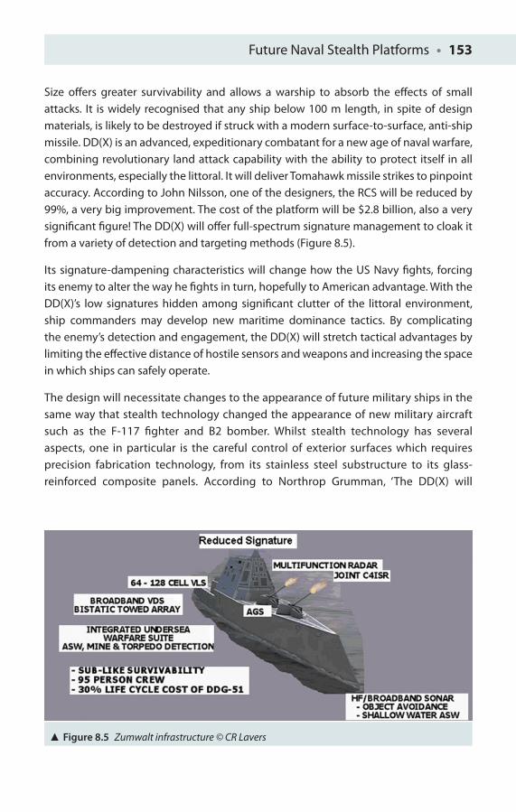
Future Naval Stealth Platforms • 153
Size off ers greater survivability and allows a warship to absorb the eff ects of small attacks. It is widely recognised that any ship below 100 m length, in spite of design materials, is likely to be destroyed if struck with a modern surface-to-surface, anti-ship missile. DD(X) is an advanced, expeditionary combatant for a new age of naval warfare, combining revolutionary land attack capability with the ability to protect itself in all environments, especially the littoral. It will deliver Tomahawk missile strikes to pinpoint accuracy. According to John Nilsson, one of the designers, the RCS will be reduced by 99%, a very big improvement. The cost of the platform will be $2.8 billion, also a very signifi cant fi gure! The DD(X) will off er full-spectrum signature management to cloak it from a variety of detection and targeting methods (Figure 8.5).
Its signature-dampening characteristics will change how the US Navy fi ghts, forcing its enemy to alter the way he fi ghts in turn, hopefully to American advantage. With the DD(X)’s low signatures hidden among signifi cant clutter of the littoral environment, ship commanders may develop new maritime dominance tactics. By complicating the enemy’s detection and engagement, the DD(X) will stretch tactical advantages by limiting the eff ective distance of hostile sensors and weapons and increasing the space in which ships can safely operate.
The design will necessitate changes to the appearance of future military ships in the same way that stealth technology changed the appearance of new military aircraft such as the F-117 fi ghter and B2 bomber. Whilst stealth technology has several aspects, one in particular is the careful control of exterior surfaces which requires precision fabrication technology, from its stainless steel substructure to its glass-reinforced composite panels. According to Northrop Grumman, ‘The DD(X) will
Figure 8.5 Zumwalt infrastructure © CR Lavers
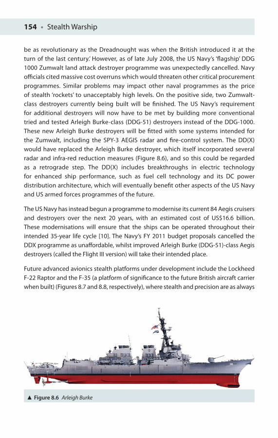
154 • Stealth Warship
be as revolutionary as the Dreadnought was when the British introduced it at the turn of the last century.’ However, as of late July 2008, the US Navy’s ‘fl agship’ DDG 1000 Zumwalt land attack destroyer programme was unexpectedly cancelled. Navy offi cials cited massive cost overruns which would threaten other critical procurement programmes. Similar problems may impact other naval programmes as the price of stealth ‘rockets’ to unacceptably high levels. On the positive side, two Zumwalt-class destroyers currently being built will be fi nished. The US Navy’s requirement for additional destroyers will now have to be met by building more conventional tried and tested Arleigh Burke-class (DDG-51) destroyers instead of the DDG-1000. These new Arleigh Burke destroyers will be fi tted with some systems intended for the Zumwalt, including the SPY-3 AEGIS radar and fi re-control system. The DD(X) would have replaced the Arleigh Burke destroyer, which itself incorporated several radar and infra-red reduction measures (Figure 8.6), and so this could be regarded as a retrograde step. The DD(X) includes breakthroughs in electric technology for enhanced ship performance, such as fuel cell technology and its DC power distribution architecture, which will eventually benefi t other aspects of the US Navy and US armed forces programmes of the future.
The US Navy has instead begun a programme to modernise its current 84 Aegis cruisers and destroyers over the next 20 years, with an estimated cost of US$16.6 billion. These modernisations will ensure that the ships can be operated throughout their intended 35-year life cycle [10]. The Navy’s FY 2011 budget proposals cancelled the DDX programme as unaff ordable, whilst improved Arleigh Burke (DDG-51)-class Aegis destroyers (called the Flight III version) will take their intended place.
Future advanced avionics stealth platforms under development include the Lockheed F-22 Raptor and the F-35 (a platform of signifi cance to the future British aircraft carrier when built) (Figures 8.7 and 8.8, respectively), where stealth and precision are as always
Figure 8.6 Arleigh Burke
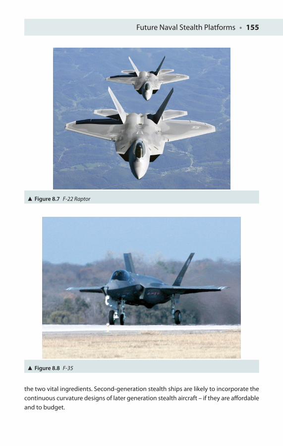
Future Naval Stealth Platforms • 155
Figure 8.8 F-35
Figure 8.7 F-22 Raptor
the two vital ingredients. Second-generation stealth ships are likely to incorporate the continuous curvature designs of later generation stealth aircraft – if they are aff ordable and to budget.
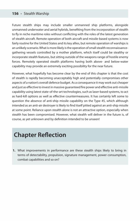
156 • Stealth Warship
Future stealth ships may include smaller unmanned ship platforms, alongside unmanned underwater and aerial hybrids, benefi ting from the incorporation of stealth to fl y in niche maritime roles without confl icting with the roles of the latest generation of stealth aircraft. Remote operation of both aircraft-and missile-based systems is now fairly routine for the United States and its key allies, but remote operation of warships is an unlikely scenario. What is more likely is the operation of small stealth reconnaissance-gathering vessels controlled by a mother platform, which itself could be stealthy or incorporate stealth features, but sitting outside of the weapons range of hostile enemy forces. Remotely operated stealth platforms having both above- and below-water capability may provide an extremely exciting possibility for the near future.
However, what hopefully has become clear by the end of this chapter is that the cost of stealth is rapidly becoming unacceptably high and potentially compromises other aspects of a nation’s overall defence budget. As a consequence it may work out cheaper and just as eff ective to invest in massive guaranteed fi re power and eff ective anti-missile capability using latest state-of-the-art technologies, such as laser-based systems, to act as hard-kill options as well as eff ective countermeasures. It has certainly left some to question the absence of anti-ship missile capability on the Type 45, which although intended as an anti-air destroyer is likely to fi nd itself pitted against an anti-ship missile at some point. Reliance upon stealth alone is not an attractive option, especially when stealth has been compromised. However, what stealth will deliver in the future is, of course, as yet unknown and by defi nition intended to be unseen!
Chapter Refl ection
1. What improvements in performance are these stealth ships likely to bring in terms of detectability, propulsion, signature management, power consumption, combat capabilities and so on?
Future Naval Stealth Platforms • 157
References
1. House of Commons Committee of Public Accounts (2011), Providing the UK’s Carrier Strike Capability. 56th Report of Session 2010–12, HC 1427. London: The Stationery Offi ce.
2. Defense Management Journal, http://www.defencemanagement.com/news_story.asp?id=18127 (accessed 2 March 2012).
3. Grenstad, A Rear Admiral (2007), ‘Future surface combatants in the Royal Swedish Navy’, RUSI Defence Systems (October): 104–106.
4. Mahon, M Rear Admiral (2009), ‘US Navy surface warfare: Future requirements and capabilities’, RUSI Defence Systems (February): 40–44.
5. Forissier, P-F Admiral (2009), ‘The French white papers goes navy blue’, RUSI Defence Systems (February): 45–47.
6. Willett, L Dr (2010), ‘Type 26: A global role for the global combat ship?’, RUSI Defence Systems, 13(2): 85–87.
7. Friedman, N Dr (2007), ‘The future surface combatant’, RUSI Defence Systems (October): 98–100.
8. HM Government (2010), Securing Britain in an Age of Uncertainty: The Strategic Defence and Security Review. London: The Stationery Offi ce.
9. ‘House of Commons Hansard – Written Answers for 16 March 2005: Column 265W’. Hansard. House of Commons. 16 March 2005. London: The Stationery Offi ce.
10. O’Rourke, R (2010), Navy Aegis Cruiser and Destroyer Modernization: Background and Issues for Congress. CRS Report for Congress. Accession No. ADA 535498, 28 September. Darby, PA: Diane Publishing.
SUMMARY
I have only one eye, I have a right to be blind sometimes … I really do not see
the signal!
Admiral Horatio Nelson
At the Battle of Copenhagen, Nelson’s commander, Sir Hyde Parker, believed the Danish fi repower was too great, and signalled for him to break off his action. Nelson ordered the signal be acknowledged but not repeated. Legend has it Nelson turned to his fl ag captain and said the above words whilst putting a telescope to his glass eye. Nelson’s action was approved in retrospect!
We have examined a large number of diff erent stealth platforms, designed over successive decades and building upon the work of others (upon the shoulders of giants), and we have considered the basic concepts of stealth or signature reduction from several spectral perspectives, namely, radar, infra-red and visible wavelengths. We have introduced the revolutionary concept of ‘metamaterials’, upon which future spectral ‘invisibility’ will crucially hinge, as well as including several other key cross sections in lesser detail, and I have related this to the design and building of the stealth ships themselves. We have also considered the known and anticipated stealth ships platforms for the current decade, but of course other designs will emerge over coming decades and from increasingly confi dent up-and-coming nations such as China and India, who are rapidly building their own independent ‘high-tech’ defence infrastructure. There is an incredible uncertainty and fl uidity in warship design at the moment, not least of which is driven by budgetary constrains.
It is hoped that the reader, once having read this introductory volume (and hopefully read more widely also) and solved some of the simple introductory mathematical problems set out at the end of each chapter, will now have a much clearer understanding of the signifi cance of stealth in modern warship platform design and the relationship to its performance.
The full cost of embarking upon stealth and/or large warship procurement generally at the start of the twenty-fi rst century needs to be more tightly constrained from the start if overspends and project cancellations are to be avoided. Some degree of restraint needs to be in place to avoid trying to introduce too much new untested technology

Summary • 159
all in one good, and a realisation that it is the integration of this new technology which also creates challenges of its own. The digital ‘nervous system’ of future platforms and indeed a seamlessly integrated fl eet will likely provide the wining edge over even the best ‘stand-alone’ systems or best platforms individually. Lessons to be learnt quickly from the Type 45 Destroyer should highlight the lack of critical capabilities, be they anti-ship missile capability or the lack of a carrier’s strike aircraft capability for an extended period, which should have been anticipated and appropriate provision or ‘cover’ established to remove or minimise these weaknesses and capability shortfalls. Nonetheless, in the harsh world of maritime operations, it is incumbent upon a ship’s crew to have this understanding of the value of stealth fi rmly embedded in their thinking so that no seemingly insignifi cant activity undertaken on board a ship, such as the use of a phone call home on the quarterdeck, could compromise its mission, the overall security of the platform or the safety of its entire crew.

APPENDIX
KEY SHIP FACTS
Queen Elizabeth-Class Aircraft Carrier, United Kingdom
Builders: BVT Surface Fleet, BAE Systems Submarine Solutions, Thales Group, Babcock Marine
Preceded by: Invincible class. Succeeded by: N/A
Planned: Queen Elizabeth, Prince of Wales
Completed: 0
General Characteristics
Displacement: 65,000 t (full). Length: 280 m (920 ft)
Beam: 39 m (waterline), 70 m overall. Draught: 9 m
Decks: 13,000 m2. Speed: 25+ knots
Range: 10,000 NM (18,520 km)
Capacity: 1,450. Complement: 600
Aircraft carried: 40 (50 full load) aircraft, including 36 F-35 Lightning II, 4 airborne early-warning
aircraft
Type 45 Destroyer, United Kingdom
Builders: BVT Surface Fleet
Preceded by: Type 42. Succeeded by: N/A
Planned: six. Building: one. Completed: fi ve. Cancelled: six. Active: 3
General Characteristics
Displacement: 7,205 t light sea going, 8,092 t deep load. Length: 500 ft
Beam: 69.5 ft. Draught: 16.4 ft
Decks: 13,000 m2. Speed: 29+ knots
Range: 7,000 NM (13,000 km)
Complement: 190 (accommodation up to 235)
Propulsion: integrated electric propulsion: two Rolls-Royce/Northrop Grumman/DCN WR-21 gas
turbines (21.5 MW), two Converteam electric motors (20 MW)
Radar:
Sampson multifunctional air tracking radar (Type 1045)
S1850M 3D air surveillance radar (Type 1046)
Two Raytheon X-band radar (Type 1047)

Appendix • 161
Weapons:
Sylver missile launcher, 48 MBDA Aster missiles (Aster 15 and Aster 30)
Two Phalanx 20 mm close-in weapons systems, one 114 mm (4.5 in.) Mk 8 gun, two Oerlikon
30 mm KCB guns on DS-30B mounts, NATO Seagnat countermeasures launchers, SSTDS
underway decoy
1 × Lynx HMA 8 helicopter or 1 × Merlin HM1 helicopter
Caio Duilio Horizon-Class Destroyer, Italy
Builder: Horizon Sass and Financier, Riva Trios and Mugging shipyards
In service: 22 September 2011
There are two ships of this class
General Characteristics
Class and type: Horizon-class frigate. Type: Destroyer
Displacement: 6,700 t (standard)
Length: 501.6 ft. Beam: 66.6 ft. Draft: 24.9 ft
Power: four diesel generators VL1716T2ME, 1,680 kW each
Propulsion: CODOG:
Two GE/Avio LM2500 gas turbine engines, 20.5 MW each
Two SEMT Pielstick 12 PA6 STC diesel engines, 4.32 MW each
Two variable pitch propellers, one bow thruster
Speed: 29 knots (gas turbine engines)
18 knots (diesel engines)
Range: 7,000 nm at 18 knots, 3,500 nm at 24 knots
Endurance: 45 days
Capacity: accommodation for 255
Complement: 24 offi cers, 87 petty offi cers, 82 sailors and 37 staff , including boarding/security
and fl ight
Surface search radar in E/F band: Selex RAN 30X/I (RASS)
Multifunctional 3D phased array radar in G-band: Selex SPY-790 (EMPAR) (principal sensor of
PAAMS)
Long-Range 3D radar (D band): Thales/Selex S1850M
Secondary surveillance radar: Selex SIR R/S
Navigation and Helo deck radar (I band): Selex SPN 753(V)4 (NAVR)
Two multi-sensor target indication system NA 25X (radar and electro-optical sensor RTN-30X)
Bispectral IR detection and tracking system Sagem (Vampir) MB (IRAS)

162 • Appendix
ESM System SLQ-750 made-up of a WB (wideband) receiver and two HSFA (Superheterodyne)
receivers
Medium frequency hull sonar Thales UMS 4110CL
Electronic warfare (Nettuno 4100):
Two radar jammers
Two Oto Melara SCLAR-H decoys launcher system for chaff and fl ares
Anti-torpedo system SLAT:
Low frequency towed array sonar
Two acoustic decoy launchers
Armament: artillery:
Three Oto Melara 76/62 mm super rapid guns (ILDS)
Two Oto Melara Oerlikon KBA 25/80 mm guns
Torpedoes:
Two EuroTorp torpedo tubes B515/1 with semi-automatic handling system for MU90
lightweight torpedoes
PAAMS (principal anti-air missile system): six DCNS Vertical Launch System Sylver A50 modules
with 48 cells for short-range Aster 15 or medium-range Aster 30 missiles and with a further
capacity for eight S/S Teseo Mk2/A missile launchers
Aircraft carried: one Agusta Westland EH101 or one NH Industries NH90 armed with MU90
torpedoes or Marte Mk2/S A/S missiles
Forbin Horizon-Class Destroyer, France
Builder: DCNS and Thales Group, Lorient shipyard
Homeport: Toulon. Fate: on trials
General Characteristics
Class and type: Horizon-class frigates with two ships in this class
Displacement: 7050 t
Length: 152.87 m. Beam: 20.3 m. Draught: 5.4 m
Propulsion:
2 × 31,280 HP GE/Avio LM2500 gas turbines
2 × 5,875 HP SEMT Pielstick 12 PA6 STC diesels
1 × beam propeller
2 × 4 blade propellers
Speed: 29 knots (18 knots diesel)
Range: 7,000 nm at 18 knots, 3,500 nm at 25 knots
Boats and landing craft carried: EDO, 20-seat EFRC, Hurricane 733

Appendix • 163
Capacity: 32 passengers or admiral staff
Complement: 26 offi cers, 110 petty offi cers, 38 sailors
Sensors and processing:
S-1850 LRR tri-dimensional sentry radar with IFF
ABF TUS 4110 CL hull sonar
Tugged linear antenna with Alto torpedo detector
Electronic warfare and decoys:
Radar jammer
Communication jammer
NGDS system (two decoy launchers, REM, RIR, LAD)
Two acoustic decoy launchers
PAAMS EMPAR multifunction radar on G band
Anti-air: 1 × PAAMS (48 × Aster 15 or 30 anti-air missiles in SYLVER A50 VLS)
Anti-ship: 8 × Exocet MM40 Block 3 anti-ship missiles
Anti-submarine: 2 × MU90 torpedo tubes
2 × Otobreda 76 mm super rapid guns
2 × 20 mm modèle F2 gun
Aircraft carried: 1 × NH90 helicopter
Visby, Sweden
Builders: Kockums
Preceded by: N/A. Succeeded by: N/A
In service: 2000. Planned: six
Completed: fi ve. HMS Visby, HMS Helsingborg, HMS Härnösan, HMS Nyköping and HMS
Karlstad
General Characteristics
Displacement: 650 t. Length: 72.6 m
Beam: 10.4 m. Draught: 2.5 m
Propulsion:
CODAG
Two KaMeWa Waterjets
Four Honeywell TF 50A gas turbines, 16 MW
Two MTU Friedrichshafen 16V 2000 N90 diesel engines, total rating 2.6 MW
Speed: 40+ knots

164 • Appendix
Complement: 27 offi cers, 16 seamen
Sensors and processing:
Ericsson Sea Giraff e ABM 3D surveillance radar
Ceros 200 fi re control radar system
Condor CS-3701 Tactical Radar Surveillance System
Hull-mounted sonar towed array sonar system
Variable depth sonar
Rheinmetall Waff e Munition MASS (Multi-Ammunition Softkill System) decoy system, which
provides radar and infra-red response simultaneously
La Fayette Frigate, France
Preceded by: Floreal-class frigate. Succeeded by: Horizon-class frigate
In service: 1996
Completed: 20
General Characteristics
Displacement: 3,200 t. Length: 125 m
Beam: 15.4 m. Draught: 4.1 m
Propulsion: four diesel SEMT Pielstick 12PA6v280 STC2, 21,000 HP (15,400 kW)
Speed: 25 knots
Range: 4,000 NM
Complement: 12 offi cers, 68 petty offi cers, 61 seamen
Sensors and processing systems:
One Air/Surface DRBV 15C sentry radar
One fi ring control radar for the 100 mm gun
One DRBN34 navigation radar
One DRBN34 landing radar
One Saigon ARBG, one radio interceptor
Two Dagaie Mk2 chaff launcher
One AN/SLQ-25 Nixie tugged noise maker
One Prairie-Masker noise reduction system (as used by the US Arleigh Burke class)
Weapons: one 100 mm TR automatic gun, two 20 mm modèle F2 guns
20 mm Crotale CN2 launcher (8 missiles on the launcher, 18 missiles in magazine). Provision for
16 Aster 15 missiles in vertical launchers
Eight Exocet MM40 block II missiles
One 10 t helicopter (Panther or NH90)
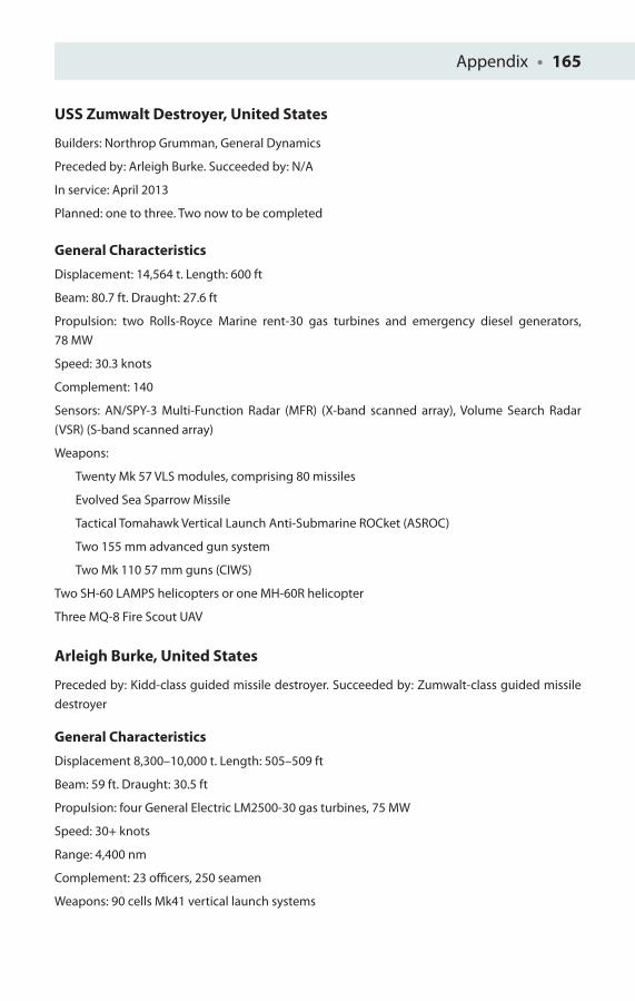
Appendix • 165
USS Zumwalt Destroyer, United States
Builders: Northrop Grumman, General Dynamics
Preceded by: Arleigh Burke. Succeeded by: N/A
In service: April 2013
Planned: one to three. Two now to be completed
General Characteristics
Displacement: 14,564 t. Length: 600 ft
Beam: 80.7 ft. Draught: 27.6 ft
Propulsion: two Rolls-Royce Marine rent-30 gas turbines and emergency diesel generators,
78 MW
Speed: 30.3 knots
Complement: 140
Sensors: AN/SPY-3 Multi-Function Radar (MFR) (X-band scanned array), Volume Search Radar
(VSR) (S-band scanned array)
Weapons:
Twenty Mk 57 VLS modules, comprising 80 missiles
Evolved Sea Sparrow Missile
Tactical Tomahawk Vertical Launch Anti-Submarine ROCket (ASROC)
Two 155 mm advanced gun system
Two Mk 110 57 mm guns (CIWS)
Two SH-60 LAMPS helicopters or one MH-60R helicopter
Three MQ-8 Fire Scout UAV
Arleigh Burke, United States
Preceded by: Kidd-class guided missile destroyer. Succeeded by: Zumwalt-class guided missile
destroyer
General Characteristics
Displacement 8,300–10,000 t. Length: 505–509 ft
Beam: 59 ft. Draught: 30.5 ft
Propulsion: four General Electric LM2500-30 gas turbines, 75 MW
Speed: 30+ knots
Range: 4,400 nm
Complement: 23 offi cers, 250 seamen
Weapons: 90 cells Mk41 vertical launch systems

166 • Appendix
BGM-109 Tomahawk
RGM-44 Harpoon SSM
SM-2 Standard SAM ASuW mode
SM-3 standard ballistic missile defence missile for Aegis BMD
RIM-162 ESSM SAM
RUM-139 vertical launch ASROC
127 mm/54 Mk-45 lightweight gun, 127 mm/62 Mk-45 mod 4 lightweight gun
Two 20 mm Phalanx CIWS DDG51-83
Two Mark 32 triple torpedo tubes (six Mk-46 or Mk-50 torpedoes)
Aircraft installed: generally none but two SH-60 Seahawk LAMPS III helos Flight IIA
DDG-51/helo ASW operations Flights I and II

GLOSSARY
AAW Anti-air warfare
APAR Active phased array radar
ASM Anti-ship missile
ASRAAM Advanced short-range air-to-air missile
ASW Anti-submarine warfare
ATC Air traffi c control
AWCT Adaptive water curtain technology
BAE British Aerospace
CCN Cloud condensation nuclei
CIC Combat Information Centre
CFRP Carbon-fi bre-reinforced plastic
CH Chain Home
CIWS Close-in weapon system
CMS Combat Management System
CVF Carrier Vessel Future
DARPA Defence Advanced Research Projects Agency
DF Direction fi nding
DIRCM Directed Infra-Red Countermeasure
ECM Electronic countermeasure
EHF Extremely high frequency
ELF Extremely low frequency
EM Electromagnetic
EMALS Electro-magnetic aircraft launch system
ESM Electronic support measures
EW Electronic warfare
FBW Fly by wire
FIR Far infra-red
FJCA Future Joint Carrier Aircraft
FSS Frequency selective surface
GCS Global Combat Ship
GRP Glass-reinforced plastic
HF High frequency
HMWHS Heavily mechanised weapons handling system
HTS High-temperature superconductor
IFEP Integrated full electric propulsion
IRAM Infra-red absorbent material
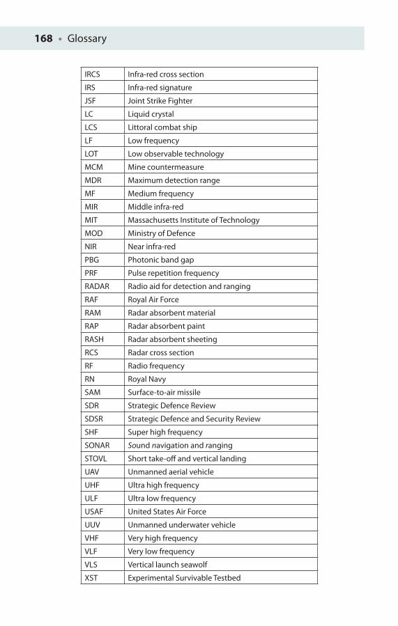
168 • Glossary
IRCS Infra-red cross section
IRS Infra-red signature
JSF Joint Strike Fighter
LC Liquid crystal
LCS Littoral combat ship
LF Low frequency
LOT Low observable technology
MCM Mine countermeasure
MDR Maximum detection range
MF Medium frequency
MIR Middle infra-red
MIT Massachusetts Institute of Technology
MOD Ministry of Defence
NIR Near infra-red
PBG Photonic band gap
PRF Pulse repetition frequency
RADAR Radio aid for detection and ranging
RAF Royal Air Force
RAM Radar absorbent material
RAP Radar absorbent paint
RASH Radar absorbent sheeting
RCS Radar cross section
RF Radio frequency
RN Royal Navy
SAM Surface-to-air missile
SDR Strategic Defence Review
SDSR Strategic Defence and Security Review
SHF Super high frequency
SONAR Sound navigation and ranging
STOVL Short take-off and vertical landing
UAV Unmanned aerial vehicle
UHF Ultra high frequency
ULF Ultra low frequency
USAF United States Air Force
UUV Unmanned underwater vehicle
VHF Very high frequency
VLF Very low frequency
VLS Vertical launch seawolf
XST Experimental Survivable Testbed

ANSWERS TO NUMERICAL QUESTIONS
Chapter 1Q3. 6.5 GHz.
Q4. 8.8 mm.
Q5. 1 km.
Q6. 92.1 km.
Q7. 19 km.
Chapter 2Q1. c = 0.2.
Q4. E = 1.2 MV m−1.
Q5. 225 nm.
Chapter 3Q1. 316.4 nm.
Q2. 400 nm.
Q3. λ/10.
Q4. (a) 4 and (b) 6.54º.
Chapter 4Q3. 16:30.
Q4. (a) 9.8 μm, (b) 404.8 W, (c) 283.97 K and (d) 10.21 μm.
Q5. Ib = I
t.
Q6. 0.57 Wm−2.
Q8. A = T/3.
Chapter 5Q3. E = 7.56 x 10⁻⁴ V.
Q4. (a) 4π x 10−11 H m−1, (b) 8π x 10−11 H and (c) E = 64π x 10−11 V.
Q5. dE/dV = μ0μ
rHL, so H = 1/(74.74π) H.

IMAGE SOURCES
IntroductionFigure I.1 Department of Defence.
Chapter 1Figure 1.6 Combat Index, LLC.Figure 1.8 Combat Index, LLC.Figure 1.9 Combat Index, LLC.Figure 1.10 Combat Index, LLC.Figure 1.16 Combat Index, LLC.Figure 1.17 Combat Index, LLC.Figure 1.18 Combat Index, LLC.Figure 1.19 Combat Index, LLC.
Chapter 3Figure 3.4 Purdue University School of Electrical and Computer Engineering, http://news.uns.purdue.edu/html4ever/2005/051130.Shalaev.negative.html.Figure 3.5 www.williamson-labs.com/ltoc/ship-stealth.htm.
Chapter 7Figure 7.17 http://www.navy.mil/view_single.asp?id=34656 File: 060506-N-4021H-122.jpg. US Navy photo by Photographer’s Mate Airman Damien Horvath. This fi le is a work of a sailor or employee of the US Navy, taken or made during the course of the person’s offi cial duties. As a work of the US federal government, the image is in the public domain.
Chapter 8Figure 8.4 US Navy photo illustration/released. http://www.navy.mil/view_single.asp?id=61727.Figure 8.7 Combat Index, LLC.Figure 8.8 Combat Index, LLC.
All other, non-credited images have been sourced from the public domain.

INDEX
AA-12 Oxcart, 8Abrams tank, 44, 45Absorption fi lters, 75Accurate Automation Corporation, 53Acoustic noise, 95
environmental factors, 97–98Acoustic threat and other signatures, 95Active sonar, 98–99
principle of, 98Active ‘cloaking’ plasma shields, 52Advanced short-range air-to-air missiles
(ASRAAM), 67–68Aegis cruisers, 154Agility, of United Kingdom, 127–128AIM-9 Sidewinder, 66Almirante Cochrane (FF-05), 120Al Riyadh-class ships, of Saudi Arabia, 136American electromagnetic aircraft launch
system (EMALS), 149Andrea Doria, 129Anti-ship cruise missile (ASCM), 63Argus, HMS, 33, 34, 35Arleigh Burke, 154–155, 165–166ASDIC technology, 97Aster missiles, 125Astrakhan, of Russia, 133Athwartship coil, 89Atmospheric sparkling, 74Atwater, Harry, 62
B Bacon, Richard, 144Band, Jonathan, 143Behm, Alexander, 96Biologically inspired design, 109–111Bioluminescence, 104–105Black and white contrast in warship, 32Black-and-white palette, 70Black-and-white stripes in warship, 34‘Boundary layer’, 106Boyle, Robert William, 97Braunschweig-class corvette, of Germany,
137–138
Brenna, Ursula, 144Burke, Arleigh, 154Burnett, Anne, 59Burnett, Robert, 59Butterlfl ies, 49Bykov, 58
C Caio Duilio Horizon-Class Destroyer, 161–162Cameron, David, 146Camoufl age, 140
active, 42face paints, 38infra-red electronic, 44origins of, 36–50real-time adaptive, 44
Carrier Vessel Future (CVF) project, see Queen Elizabeth-Class Aircraft Carrier
CATOBAR system, 147, 149Cavitation, 102–103Chain Home, 1, 2Charles S. Sperry (DD-697), USS, 34, 35China’s Yantai, 138–139Chinese ‘Nantsin’ radar, 27Cholesteric liquid crystals, 46Clarke, Arthur C, 110Cloud condensation nuclei (CCN), 111Combat Management System (CMS), 120Combined diesel-electric and gas (CODLAG)
propulsion system, 120Committee of Imperial Defence, 1Common anti-air modular missile (CAMM), 151Contrast formula, 40Copper-cabled systems, 91Corner refl ector, 24Cottesmore, HMS, 94Cubist patterns, 40, 41Cuttlefi sh, 47, 48
D Dallenbach layer, 23Daring (D32), HMS, 121, 122, 123, 124, 126Daring class, see Type 45 DestroyerDazzle camoufl age, 33, 35, 41, 42
and fi rst world war, 30–36

172 • Index
Dazzle painting, 33D-band Thales S1850M, 129DD(X) Zumwalt, US Navy, 152Degaussing coils, 90Degaussing Ships’ Hulls, 86Directed Infrared Countermeasures (DIRCM),76Direction fi nding (DF), 1
E Eldridge, 63Electric fi eld, strength of, 46Electromagnetic (EM) spectrum, 69, 4, 5Electromagnetic (EM) waves, 52ELF signature, see Extremely low-frequency
(ELF) signatureEmissions control policy, 111EML Admiral Cowan, 93Endara, Guillermo, 18European Aeronautic Defence and Space
(EADS), 44Experimental Survivable Testbed (XST)
programme, 10Extraordinary acoustic screening (EAS), 103Extremely low-frequency (ELF) signature, 108
FF-15 Eagle, 53F-22 Raptor, 155F-35B Lightning, 143, 144, 146–147F-35 Lightning, 19, 122, 144, 154F-117A Nighthawk, 9, 32Face paints of camoufl age, 38‘Faceting’, 11False colour palette, 71Far infra-red (FIR), 72Fessenden, Reginald, 96Field-emission scanning electron microscope
image, 61‘Fixed’ dazzle camoufl age patterns, 36Flux density, 83‘Fog of war’, 32, 37Forbin (D620), 130Forbin Horizon-Class Destroyer, 162–163Forecastle induced–quarterdeck induced (FI-QI)
coils, 88Forecastle permanent–quarterdeck permanent
(FP-QP) coils, 88Formidable-class frigate, of Singapore, 136–137France
Forbin Horizon-Class Destroyer, 162–163French destroyer variant, 130
La Fayette Frigate, 164modern stealth ships of, 134–136
Frequency selective surfaces (FSS), 115Future acoustic technology, 103–104Future Joint Combat Aircraft (FJCA), 144Future naval stealth platforms, 141Future surface combatant (FSC) platforms,
141
GGerman air force, 31German Heinkel He 111s, 3, 4Germany’s Braunschweig-class corvette,
137–138Glass-reinforced plastic (GRP), 82, 92Glint, 4, 33, 41Goodeve, Charles, 86Göring, Reich Marshal Hermann, 6Grumman, Northrop, 153–154
HHammond, Philip, 147Have Blue aircraft, 15–17‘Have Blue’ design, 9, 15Heat-seeking missiles, 68Highly mechanised weapons handling system
(HMWHS), 146High-temperature superconducting
(HTS), 91Hopkins, Evan, 86Horizon-class frigate Caio Duilio (D554), 128Horten, Reimar, 6Horten, Walter, 6Horton H. IX designs, 7Hughes AIM-4 Falcon, 66Hydroacoustics, 96
II-band SPN 753(V)4, 129Ideopsis similis butterfl ies, 48Incident radar wave, 22India, modern stealth ships of, 132
INS Kolkata, 132Shivalik-class frigates, 132
Indium tin oxide (ITO), 19Infra-red, 66
emission, 73laws of emission, 78–79
Infra-red absorbing materials (IRAM), 75Infra-red cross section (IRCS), 69
contributors, 71

Index • 173
Infra-red electronic camoufl age, 44Infra-red Heat Reduction, 66Infra-red signature (IRS), 69Infrasonic frequencies, 96INS Kolkata, of India, 132Integrated electric propulsion (IEP), 127Integrated full electric propulsion (IFEP), 127Interference theory, 23‘Iron ball’ paint, 19Italian destroyer variant, 128–129Italy’s Caio Duilio Horizon-Class Destroyer,
161–162
JJohnson, Clarence, 8
KKeldysh Research Centre, 52–53Kent, HMS (far infra-red), 72‘Khaki’, soldier’s uniform in, 32, 37Kirov, 133Kirtland Air Force Base (AFB), 53Koroteyev, Anatoliy, 52–53Krauss, Thomas, 58
LLa Fayette class, of France, 134–136, 164Laird, Cammell, 148Laser area defence system (LADS), 110–111Likely future cross sections, 108–109‘Lines of fl ux’, 83‘Lines of force’, 83Liquid crystal displays (LCD) electronic
products, 46Lockheed ‘Skunk Works’, 8, 10–11, 18Long-range 3D radar, 129Los Alamos National Laboratories, 53Lossy layer, 23‘Lotus eff ect’, 109–110Lovell, Jim, 104Low-frequency active sonar (LFAS), 101
MM80 Stiletto, of United States of America,
130–132Magnetic anomaly detection (MAD), 89Magnetic fi eld of bar magnet, 83Magnetic permeability, 56Magnetic signature, 82–95Magnetic stealth, 82–87Main coil (M), 87
Marine bioluminescence, 105Martin, Kelly, 6Materials, of radar, 19Maximum Detection Range (MDR), 13–19Maxwell, James Clerk, 11Metamaterials, 54N-(4-Methoxybenzylidene)-4-butylaniline
(MBBA), 46Micro air vehicles (MAVs), 44Middle infra-red (MIR), 68Middleton, HMS, 94Military sonar, 99Mine countermeasure (MCM) sonar, 101Modern stealth ships, 114
Agility, of United Kingdom, 127–128Al Riyadh-class ships, of Saudi Arabia, 136Astrakhan, of Russia, 133Braunschweig-class corvette, of Germany,
137–138Formidable-class frigate, of Singapore,
136–137French destroyer variant, 130INS Kolkata, of India, 132Italian destroyer variant, 128–129La Fayette class, of France, 134–136M80 Stiletto, of United States of America,
130–132PAAMS, of United Kingdom, 125–126Shivalik-class frigates, of India, 132Type 23 Frigate, of United Kingdom,
119–120Type 45 Destroyer, of United Kingdom,
121–125Visby stealth corvette, of Sweden,
114–119Yantai, of China, 138–139
Morpho, 47, 48Multiple RAM layers, 19
NNanoperm, 85Nanorods, 59, 60Nano-structured zinc oxide replica wing
structures, 48‘Nantsin’ radar, 27Near infra-red (NIR), 70
vegetation in, 38–39wavelengths, 59
Negative refractive index, 57Nilsson, John, 153
174 • Index
NIRATAM, 77Norfolk, HMS, 120
OOne-dimensional (1D) photonic crystals, 57Opal, 57Optical fi lters, 75Optical glint, 41Optical illusions, creation of, 31Optical metamaterials, 59–64Optoelectronic Research Centre (ORC), 58Overholser, Denys, 12
PPAAMS components, of United Kingdom,
125–126Passive sonar, 99–100Peacock feather, 20, 21Pendry, John, 60Philadelphia Experiment, 63Photonic band gap (PBG), 56
nanostructures, 47Photonic crystals, 54, 56‘Plasmons’, 59Prince of Wales, HMS, 142‘Project Harvey’, 10Project Yehudi, 43Pulse delay ranging, of radar, 4, 5
QQueen Elizabeth, HMS, 142, 148–149Queen Elizabeth-Class Aircraft Carrier, 142, 160Quorn, HMS, 94
RRadar, 1
metamaterials, 54–59and weapons systems, 146
Radar absorbent material (RAM), 6Radar absorbent paint (RAP), 17Radar cross section (RCS), 10Radio-frequency (RF) electric pulse, 52RAMs, 19Raven, Alan, 31Rayleigh, Baron, 57Rayleigh, Lord, 57‘Razzle Dazzle’, 33Real-time adaptive camoufl age, 44Refl ected radar wave, 22Reinitzer, Friedrich, 46Richardson, Lewis, 96
River Dart taken in visible, near infra-red and thermal bands in autumn, 38
RMS Mauretania, 36RMS Olympic, 36Roach motel, 11Royal Academy of Arts, 31Russell, Philip St John, 58Russia’s Astrakhan, 133
SSajeey, John, 58Salisbury screen, 21Sandia National Laboratories, 53Sandown, HMS, 93Saudi Arabia’s Al Riyadh-class ships, 136Scale invariance, 58Scherrer, Dick, 10Schroeder, Bill, 12Schurig, David, 62Scintillation, 74Sea Shadow, 24, 25Shalaev, Vladimir, 59Shivalik-class frigates, of India, 132Short take-off and vertical landing
(STOVL), 143Shuttle heat tiles, in U.S., 7, 8Singapore’s Formidable-class frigate,
136–137Smith, David, 62Smoke, 32Soldier’s uniform, 37Sonar, 95Sonar comparison, 101–102Sophisticated submarine camoufl age
schemes, development of, 49Soviet-made surface-to-air missiles
(SAMs), 8SPIRITS, 77Splinter camoufl age, 37SR-71, 8–11, 33SS Industry, 31Stealth aircraft, 33Stefan–Boltzmann constant, 79Stennis, John C., 143Stewart, James, 10STOVL F-35B Lightning II variant, 144Strategic Defence and Security Review
(SDSR), 142Strategic Defence Review (SDR), 144Strutt, John William, 57

Index • 175
Sub-surface very low frequency (VLF) imaging, 109
Sukhoi Su-27 IB fi ghter-bomber, 53Surface plasmon resonance (SPR)
sensors, 58Swallowtail butterfl y, thermal image of, 49Swedish Navy’s Visby stealth corvette,
114–119, 163–164
TTesla, Nikola, 84Thales Sonar 2087, 101Thermal imaging cameras (TICs), 70Thornycroft, Vosper, 93Titanic disaster of 1912, 96Tizard, Henry, 1Transmission stop band, 57Transparent monoplane, 31Type 23 Frigate, of United Kingdom, 119–120Type 26 frigate, 151Type 45 Destroyer, 117, 160–161
power distribution system of, 122of United Kingdom, 121–125
UU2 aircraft, 33Ufi mtsev, Pyotr, 12UK FSC /Type 26 Frigate, 149–151Ultrasonic frequencies, 96Ultraviolet (UV) spectrum, 108‘Underwater acoustics’, 96Underwater vehicle (UUV), 151Unidentifed fl ying objects (UFOs), 18Uniform of soldiers, 37United Kingdom
Agility, 127–128modern stealth ships of, 119PAAMS components, 125–126Queen Elizabeth-Class Aircraft Carrier, 160Type 23 Frigate, 119–120Type 45 Destroyer, 121–125Type 45 Destroyer, 160–161
United States Air Force (USAF), 8United States of America
Arleigh Burke, 165–166
DD(X) Zumwalt, US Navy, 152M80 Stiletto, 130–132modern stealth ships of, 130Zumwalt Destroyer, USS, 165
US adaptive water curtain technology (AWCT), 62–63
US Defense Advanced Research Projects Agency (DARPA), 8
US Navy aircraft carrier, 143US Navy Sikorsky SH-3H Sea King
helicopter, 102
VVegetation in the near infra-red, 38–39Vertical launch seawolf (VLS), 151Victory, HMS, 20Vietnam War, 66Visby, 44, 163–164Visby stealth corvette, 41, 42, 44, 45
of Swedish Navy, 114–119Visibility
camoufl age, origins of, 36–50dazzle camoufl age and First World
War, 30–36
WWaggonfabrik, Gothaer, 6Wake eff ects, 105–108Warships, 82Watson-Watt, Robert, 1, 3Weapons and systems, 151Wilkinson, Lt Norman, 30–31, 35WR21 complex cycle gas turbine, 121–122Yablonovitch, 58
YYablonovitch, Eli, 58Yantai, of China, 138–139Yarrow Shipbuilders Limited, 94
ZZumwalt, Elmo, 152Zumwalt Destroyer, USS, 165Zumwalt infrastructure, 153Z zone, 87