Embed Size (px)
Citation preview

State of Practice in Soil Liquefaction Mitigation and Engineering Countermeasures
Emilio M. Morales, MSCE1]
Mark K. Morales, M.Sc.2]
Summary
The threat of Soil Liquefaction is all too real and the damage wrought to Dagupan City and other
areas due to liquefaction during the 1990 Luzon Earthquake indicate the need to provide
engineered responses to mitigate or eliminate the threat.
With the anticipated build up in private infrastructure and development, the availability of cheap
land is becoming scarcer and scarcer and therefore, focus is being directed into the development
of marginal lands which invariably would involve some risks due to potential for liquefaction and
other geotechnical concerns.
Particularly in the Philippines which is in a very active Seismic Zone, with very long coastlines
with marine sedimentary deposits and inland alluvial valley deposits, potentially liquefiable loose
to very loose granular soil deposits are prevalent.
This paper discusses the phenomenon of soil liquefaction, the causative mechanisms and the
“State of the Art” approaches to determining liquefaction susceptibility of a specific soil deposit
and the factor of safety.
This is followed by current “State of Practice” discussion addressing anti-liquefaction counter
measures and mitigation methodologies available to engineers and developers.
1] MSCE major in Geotechnics and Structures, Carnegie Mellon University, Pittsburgh, PA., Chairman, PICE Geotechnical Specialty Division., Principal, EM2A Partners & Co. 2] M.Sc. Master of Science major in Earthquake Geotechnical Engineering, University of California – Berkeley, CA. Managing Director , Philippine GEOANALYTICS Inc. contact : www.pgatech.com.ph
Page 1 of 29

1.0 INTRODUCTION
1.1 General
Soil liquefaction is a sudden loss in strength in loose to very loose saturated granular soils due to
ground shaking followed by a rapid increase in pore pressure. The ground shaking, which is
normally due to earthquakes or significant horizontal shearing and excitation of the loose to very
loose soils, momentarily causes dislodgement of the precarious grain to grain contact of the
individual soil grains.
A different phenomenon on soft to very soft cohesive soils, which has been wrongly attributed as
soil liquefaction in the past, is another mechanism caused by repeated cyclic shearing of the
soils. Particularly in very sensitive soils, the cyclic disturbance causes a significant loss in shear
strength which could result in instability or bearing capacity failures. This second phenomenon is
not addressed in this paper as it is a totally different failure mechanism with the same causative
or triggering events.
Rapid increases in porewater pressure normally accompany this ground shaking. Due to the
dislodgement, the superimposed weight on the ground is momentarily transferred to the
porewater because the soil loses its strength due to loss of grain to grain contact. This
momentary transfer further increases the porewater pressure in the saturated zone further
buoying up the already dislodged soil grains. Buoyancy causes the total collapse of the soil
structure resulting in a “liquefied mass” which does not possess any shear strength or load
carrying capacity.
Thus, the loads (structures) imposed on the soil before the liquefaction which originally was
deemed “stable” momentarily loses the soil support leading to partial collapse or tilting to total
collapse.
The following effects of Liquefaction can occur in a vulnerable site when liquefaction is induced
by significant ground shaking:
• Lateral Spreading from Liquefaction. Lateral deformation induced by earthquakes is
discussed below.
Page 2 of 29

• Lateral Deformation. The occurrence of liquefaction and its associated loss of soil
strength can cause large horizontal deformations. These deformations may cause failure
of buildings, sever pipelines, buckle bridges, and topple retaining walls.
Three types of ground failure are possible. Flow failures may occur on steep slopes.
Lateral spread may occur on gentle slopes.
Figure 1.1 Examples of Lateral spreading due to Liquefaction. 3]
Page 3 of 29

The third type of failure involves ground oscillation on flat ground with liquefaction at depth
decoupling surface layers. This decoupling allows rather large transient ground oscillation or
ground waves.3]
In the past, as in the present, empirical and semi-empirical methods have been used in order to
assess the liquefaction susceptibility of a site. This ranged from the use of comparison charts of
characteristic grain size envelopes of sites worldwide that have liquefied in the past (see Figure
3.1.1 ) on which the characteristic grain size of a specific site is superimposed, the use of rule of
thumb checks, to the development of the Cyclic Resistance ratio (CRR). Even in the latter
procedure, which is now universally accepted, recent developments in the understanding of
liquefaction has resulted in significant changes in our understanding of this phenomenon in soils,
its assessment as well as the feasible countermeasures to mitigate or reduce the effects on civil
engineering structures.
.
It is the purpose of this paper to look into possible liquefaction mitigation technologies and
discuss their effectiveness. 2.0 BACKGROUND ON LIQUEFACTION
Liquefaction is sudden loss of soil strength due to flotation of the individual soil grains from
excess pore pressure and ground shaking during an earthquake.
However, before Liquefaction can occur the following conditions need to be satisfied which
according to Seed 4] are:
• Soil-type - Soils with 50% or more of their grain size in the range of 0.02mm to 0.2mm
are potentially liquefiable when saturated.
• Intensity of Ground Pressure - To initiate liquefaction local ground acceleration greater
than 0.10g is required.
3] US DOD NAVFAC DM 7.4 “Soil Dynamics and Special Design Aspects” 4] Seed & Idriss:” Simplified Procedure for Evaluating Soil Liquefaction Potential" Journal of ASCE SM9 September 1971.
Page 4 of 29

• Initial Confining Pressure - The stress required to initiate liquefaction increases with
confining pressure.
• Duration of shaking - It is necessary for the shaking to continue for some time (a
characteristic of large earthquakes).
Liquefaction associated failure may be of the following types:
• Tilting due to instability
• Direct settlement due to loss of bearing capacity
• Uplift due to buoyancy effects
• Translation of structure
3.0 LIQUEFACTION ASSESSMENT
Most of the discussions in this Section were lifted from a “State of the Art” paper by Seed et al 5]
3.1 Analysis of Liquefaction
, t
3.1.1 Empirical Correlations
Empirical correlations were based essentially on comparison of Grain size distribution of the site
to the grain size envelope of sites that have liquefied in the past worldwide. This follows the work
of Nishida Fit on and others as well as recorded liquefaction at Turnagain Heights in Alaska.
If the grain sizes of the target site fall within the envelope of grain sizes that have liquefied in the
past, then most likely the site will also experience liquefaction given an earthquake large enough
to cause shearing and dislodgement of the loose to very loose sands.
A sample of this procedure is shown below and is used still to gage susceptibility to liquefaction
in conjunction with other methods.
5] R. B. Seed “Recent Advances in Soil Liquefaction Engineering-a Unified and consistent Framework” 26th Annual ASCE Los Angeles Geotechnical Spring Seminar.
Page 5 of 29

Fig. 3.1.1 - Comparison of Grain Size with Envelope of Grain Size that Liquefied in the past.
3.1.2 The “Simplified Procedure” by Seed and Idriss
Analytical Evaluation of liquefaction potential of a site is based originally on the pioneering work
by H Bolton Seed and Idriss (1971) The “simplified procedure” originally developed involves the
calculation of the Factor of Safety obtained by determining the Cyclic Resistance Ratio and Cyclic
Stress Ratio of the site soils. The method has been modified and improved by several
researchers. The current “simplified procedure” calculates the factor of safety, FS, against
liquefaction in terms of the cyclic stress ratio, CSR (the demand), and the cyclic resistance ratio,
CRR (the capacity), according to the formula:
Page 6 of 29

where:
CRR7.5 is the cyclic resistance ratio for magnitude 7.5 earthquakes, MSF is the Magnitude scaling
factor, Kσ is the overburden correction factor, and Kα is the correction factor for sloping ground.
CSR is estimated using the Seed and Idriss (1971) equation multiplied by 0.65:
where:
amax is the peak horizontal acceleration at the ground surface generated by the
Earthquake,
g is acceleration due to gravity,
σvo and σ’vo are the total and effective overburden stresses, respectively, and
rd is the stress reduction coefficient.
Other than the purely empirical grain size comparisons, the three commonly used methods to
evaluate the liquefaction resistance, CRR, Gutierrez Ref 6] are:
1) Using the Standard Penetration Test (SPT),
2) Using the Cone Penetration Test (CPT), and 3) Using Seismic Shear wave velocity
Associated uncertainties in the development of probabilistic methods for liquefaction risk analysis
based on the “simplified” method are:
1) the uncertainty in demand particularly the maximum acceleration amax and the earthquake
magnitude Mw , required to estimate the magnitude scaling Factor MSF and
i6] M. Gutierrez, J. M. Duncan, C. Woods and M. Eddy “ Development of a Simplified Reliabil ty-Based Method for
Liquefaction Evaluation” Civil and Environmental Engineering Virginia Polytechnic Institute & State University
Page 7 of 29

2) the uncertainty in the capacity CRR . For CRR, the uncertainties are due to natural
variability of the soil and geotechnical properties, in-situ testing procedures, and most
importantly the simplified method. Gutierrez 4 ]
Recent researches into this field have resulted in further refinements in the procedure particularly
in both the “deterministic” and “Probabilistic” determination of liquefaction potential.
In a recent groundbreaking publication by Raymond Seed et al known as the Queen Mary Paper,”
ref
3] refinements in the procedure over that of the “simplified” Seed (Senior) procedure have
been proposed.
New models presented and described in this specific research paper deal explicitly with the issues
of:
(1) Fines content (FC),
(2) magnitude-correlated duration weighting factors (DWFM), and
(3) Effective overburden stress (Kσ effects),
and they provide both
(1) An unbiased basis for evaluation of liquefaction initiation hazard, and
(2) Significantly reduced overall model uncertainty.
3.1.3 Influence of Fines Content and Plasticity
The fines content (% passing No 200 sieve), more specifically Plasticity of these fractions greatly
influences the susceptibility to liquefaction.
The chart below is the recommendation from the paper by Seed et al 3] regarding the influence
of the fines content, more specifically the effects of its Liquid Limit LL and Plasticity Index PI on
the liquefiability of soils.
Page 8 of 29
For soils with sufficient fines content that the Fines separate the coarser particles and control
overall behavior:
(1) Soils within Zone A are considered potentially susceptible to “classic” Cyclically induced
liquefaction,
(2) Soils within Zone B may be
Liquefiable, and
(3) Soils in Zone C (not within Zones A or B) are not generally susceptible to “classic” cyclic
liquefaction, but should be checked for potential sensitivity (loss of strength with
remolding or monotonic accumulation of shear deformation).
It has been found out that for soils with sufficient fines content FC, the characteristics of the fine
fractions greatly influences susceptibility to cyclically induced Liquefaction.
3.1.4 Magnitude Correlated Duration Weighting DWFm
Both the probabilistic and “deterministic” (based on PL=20%) new correlations presented in
Figures 10 and 11 are based on the correction of “equivalent uniform cyclic stress ratio” (CSReq)
for duration (or number of equivalent cycles) to CSRN, representing the equivalent CSR for a
duration typical of an “average” event of MW = 7.5. This was done by means of a magnitude-
correlated duration weighting factor (DWFM) as:
Page 9 of 29

CSRN = CSReq,M=7.5 = CSReq, M=M / DWFm -> (a)
This duration weighting factor has been somewhat controversial, and has been developed by a
variety of different approaches (using cyclic laboratory testing and/or field case history data) by a
number of investigators.
The Chart below shows the Duration Weighting Factor DWFm with a value of 1.0 for an
earthquake Magnitude of 7.5. Thus for M > 7.5 the DWFm is less than 1.0 resulting in a higher
CSRN in equation (a) above.
3.1.5 SPT Based Triggering Correlations
One of the more important contributions of the Queen Mary Paper is in the improvement of the
SPT based correlations which has reduced the uncertainty in the use of such charts in the past.
For one, Key elements in the development of this new correlation were:
(1) Accumulation of a significantly expanded database of field performance case histories,
(2) Use of improved knowledge and understanding of factors affecting interpretation of SPT data,
(3) Incorporation of improved understanding of factors affecting site-specific ground motions
(including directivity effects, site-specific response, etc.),
(4) Use of improved methods for assessment of in-situ cyclic shear stress ratio (CSR),
(5) Screening of field data case histories on a quality/uncertainty basis, and
Page 10 of 29

(6) Use of higher-order probabilistic tools (Bayesian Updating).
The charts below are the recommended procedure for determining Probabilistic and Deterministic
Cyclic Stress Ratio (CSR) from the corrected and normalized SPT Nvalues. The probabilistic chart
shows a family of curves based on Probability values (PL), while for the Deterministic Chart; the
family of lines represents different Fines content (FC) values. The solid data points represent
correlated “liquefied” zones while the unshaded data points represent sites that have not
liquefied.
t
However, before these could be applied, corrections on the SPT values need to be made as follows:
• Correction for Hammer Energy • Correction for Rod Length • Correction for Overburden stress • Procedural corrections
The discussion of the foregoing effects is outside the scope of this paper. However, the reader is referred to the paper by Seed et al 5].
The downloadable .pdf version can be downloaded at : www.pga ech.com.ph
4.0 LIQUEFACTION COUNTERMEASURES AND MITIGATION OF EFFECTS
4.1 General
Page 11 of 29

There are several procedures to mitigate or eliminate the harmful effects of liquefaction ranging
from hard responses to simple avoidance.
These are:
• Site Selection - Potentially liquefiable areas can be identified and avoided. However, as
premium lands become scarcer, marginal lands become attractive and thus this solution
may not be commercially acceptable to developers.
• Use of piling to bypass the potentially liquefiable zones. This is the brute force solution.
Piling would need to be designed for the unsupported length equivalent to the liquefied
depth and for potential negative skin friction from clay layers overlying liquefiable zones.
Detailing would also be under Seismic Zone 4 Conditions.
• Chemical or Cement Injection grouting to solidify the liquefiable soils . The
permeability of the target soils should be determined to assure proper grout dispersion.
Injection points may be numerous as grouting pressure can not be boosted or hydro
fracturing can result.
o Joosten 2 Part Process
o Portland cement Injection.
However, the State of Practice has evolved through the years, to make available cost effective
liquefaction mitigation technologies
that could be effectively used in countering liquefaction or in preventing the build-up of the
critical conditions before set up of liquefaction.
Among these are:
• Ground Densification - The liquefiable loose to very loose grounds can be densified to
the desired density to eliminate its susceptibility to liquefaction.
o Compaction Piling / Resonant Column
o Dynamic Compaction
o Vibratory Methods
o Stone Columns / Vibroflotation
o Rammed Aggregate Piers
Page 12 of 29
ADO3.0 3.0
10.0
Sand
Silty Sand Treated by Pemeation
mical GrouChe ting
MH SOILS
ADO TANK
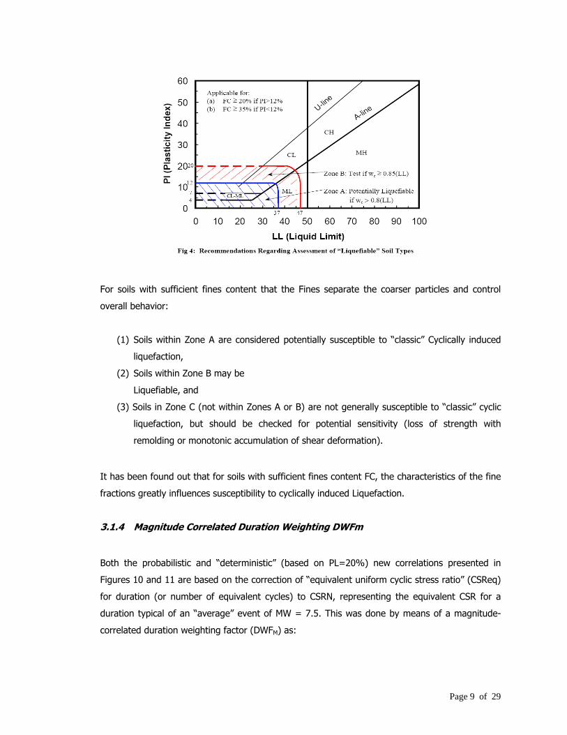
Figure 4.1 - Showing Ground Improvement Through Permeation or Chemical Grouting
• Pore water Relief- pore pressure buildup during the initiation of liquefaction can be
prevented by rapid drainage.
o Prefabricated Vertical Drains / Sausage Drains
o Granular Piles
• Compaction Grouting - is defined as the staged injection of low slump (less than 3
inches) mortar-type grout into soils at high pressures (500 to 600 pounds per square
inch), is used to densify loose granular soils. At each grout location a casing is drilled to
the bottom of a
previously specified soil target zone. Compaction grout is then pumped into the casing at
increments of one lineal foot. When previously determined criteria are met such as
volume, pressure, and heave, pumping will be terminated and the casing will be
withdrawn. The casing will be continuously withdrawn by one foot when it meets
previously determined criteria until the hole is filled. 3]
Page 13 of 29

4.2 Ground Improvement Procedures
r
4.2.1 Strength Increase of Loose Sand Deposits with Vibratory Densification
Procedures
Ground Densification procedures have the beneficial effect of improving the ground through
densification and also through reinforcement of very poor clayey soils and to some extent in the
acceleration of the consolidation process through adial drainage into the permeable granular
columns. In addition, the densified granular columns serve to carry the major part of the load
because of its relatively very high stiffness compared to the surrounding matrix soil.
The strength gain of the soil with time is also one of the beneficial effects.
In addition, performance of granular piles in the Hyogen-Nambu (Kobe) Earthquake has shown
that areas improved with Granular piles did not fail during the liquefaction event, whereas
surrounding areas that were not improved showed significant damage and collapse of structures.
In this case, the granular piles serve as Chimney drains to relieve the pore pressures.
But of more critical importance is the almost immediate strength gain through reinforcement of
the weak subsoils by densified columnar elements. The failure plane or the slip circle has to pass
through and cut through the relatively very dense granular materials before it can propagate any
further. In effect, the factor of safety is enhanced by the reinforcing effect of the Granular
columns with large Angle of internal friction. 4.2.2 Generic and Proprietary Ground Densification using Vibratory Method
4.2.2.1 Compaction Piling/Resonant Column
Compaction piling, using steel rigid steel retractable mandrels, are driven at regular intervals or
spacing in triangular or square array, within the liquefiable soils. The mandrel is then withdrawn
and the hole is backfilled with sand. The mandrel is then redriven and retracted until full
treatment depth has been completed.
Page 14 of 29

4.2.2.2 Resonant Column Apparatus
This is a proprietary German technology which drives a steel probe attached to a vibratory
equipment which induces vibration through the probe. The vibrating frequency is chosen at or
near the Resonant Frequency of the soil to be densified. Thus, resonance builds up and the loose
soils vibrate in themselves causing a denser packing to be achieved. The target density or Nvalue is
controlled through the spacing of the insertion of the probe.
4.2.2.3 Dynamic Compaction
Dynamic compaction, developed by the late Louis Menard and originally marketed as Dynamic
consolidation became popular in the seventies. The procedure involves the dropping of a heavy
tamping weight over a free fall height of greater than 10 meters in order to cause shock waves
The effective depth of treatment depends on the energy of the falling weight as it impacts on the
ground. Empirically, the effective depth De of treatment is given as:
De = f √ W*H
Where:
D=Effective depth of Treatment ft
f= a constant depending on the
soil (normally ½ )
W=Impact weight kips
H=freefall height
In order to avoid impact energy losses, a single line crane must be used to lift the weight. Thus,
relatively heavy lift capacity cranes are needed to lift the weight due to lack of mechanical
advantage derived from multiple pulley systems.
The depth of treatment based on the largest system ever built, is approximately 8.0 meters.
Beyond this depth, energy from the surface is dissipated resulting in significantly reduced
compaction.
Page 15 of 29

Figure 4.2.2.1 Mammoth DC Equipment
Several drops are needed to finish one location with the interval between drops governed by the
pore pressure dissipation.
Treatment procedures 7] would be different for various types of soils. PVD’s would need to be
installed in clays and impermeable soils to aid in drainage and rapid pore pressure decay.
7] Nashed, R. “ A Design Procedure for Liquefaction Mitigation of Silty Soils using Dynamic Compaction”
Page 16 of 29

4.2.2.4 GEOPIER Impact Piers®
The Impact Pier® is a Proprietary Technology developed by Geopier Corporation 8] similar to
stone columns in some respects but achieving higher aggregate column stiffness due to the
patented beveled tamper foot. The Impact System uses vertical displacement Rammed
Aggregate Piers (RAPs) to reinforce good to poor soils, including loose sands, silts, mixed soil
layers including clays, uncontrolled fill and soils below the ground water table.
The installation process displaces soil during installation and utilizes vertical impact ramming
energy to construct vertical displacement RAPs, which exhibit high strength and stiffness. The
RAP procedure is designed to provide total and differential settlement control and increase
bearing support.
The cavity is created to full depth by pushing a specially designed mandrel and tamper foot using
a relatively large static force augmented by dynamic impact energy. This method eliminates
spoils as all penetrated spoils are displaced laterally. A sacrificial cap prevents soil from entering
the tamper foot and mandrel.
After driving to design depth, the hollow mandrel serves as a funnel for the placement of
aggregate. The aggregate is placed inside the mandrel and the mandrel is lifted, leaving the
sacrificial cap at the bottom of the pier. The tamper foot is lifted approximately three feet and
then driven back down two feet, forming a one-foot thick compacted lift. Compaction is achieved
through static force and dynamic impact energy from the hammer.
The Impact hammer blows densify aggregate vertically and the patented 45° beveled tamper
foot forces aggregate laterally into cavity sidewalls. This results in effective coupling with
surrounding soils and Settlement control and strength and stiffness. The lateral compactive
energy results in prestressing and Prestraining the matrix soil.
8] www.geopiers.com
Page 17 of 29

Fig 4.1 – Impact Pier Equipment The RAP can develop Friction Angles of 42 to 48 depending on the aggregate and confining
matrix soil.
Fig 4.2 - Conventional GEOPIER Installation Equipment
Page 18 of 29
4.2.2.5 Vibrodensification or Vibroflotation®
Vibrodensification using proprietary technologies consists of introducing a rigid vibratory steel
mandrel into the granular soil to be densified by vibratory excitation. This method is used
primarily for densifying clean granular Cohesionless soils. The action of the vibrator usually used
in conjunction with water jetting momentarily reduces the intergranular friction of the loose sand
grains causing these to assume a denser state due to vibratory excitation. Granular material
(sands and gravels) is dropped down the annular cavity between the mandrel and soil.
However, care must be used in order to prevent uplift or heaving of previously installed columns.
The granular materials are dropped and vibrated by a vibratory hammer. The resulting vibration
results in densification of the coarse grained materials and the surrounding loose sand layers.
Although the surrounding very soft clays would not generally densify, the densified sand columns
will act as vertical reinforcement to increase the composite shear strength of the sub seabed clay
soils. In addition, the sand columns will serve as vertical drains to accelerate the consolidation
process by reducing drainage paths and providing for increased pore pressures momentarily
during installation as to accelerate the drainage process further.
The accelerated consolidation will also allow for the accelerated development of increased shear
strengths. In thick very poor cohesive soils, Vibroflotation may not be as effective as bulging of
the vibroflot pile may result. This should be avoided as significant load reduction due to bulging
could occur.
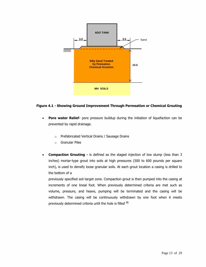
Vibroflotation operates effectively within a certain Grain Size Envelope as shown below:
Figure 4.2.2 Grain Size Envelope Showing Applicability of Vibroflotation (from
Vibroflotation Website)9]
.9] www.vibroflotation com
Page 19 of 29
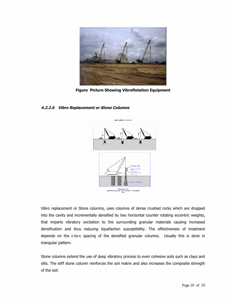
Figure Picture Showing Vibroflotation Equipment
4.2.2.6 Vibro Replacement or Stone Columns
Vibro replacement or Stone columns, uses columns of dense crushed rocks which are dropped
into the cavity and incrementally densified by two horizontal counter rotating eccentric weights,
that imparts vibratory excitation to the surrounding granular materials causing increased
densification and thus reducing liquefaction susceptibility. The effectiveness of treatment
depends on the c-to-c spacing of the densified granular columns. Usually this is done in
triangular pattern.
Stone columns extend the use of deep vibratory process to even cohesive soils such as clays and
silts. The stiff stone column reinforces the soil matrix and also increases the composite strength
of the soil.
Page 20 of 29

The stone columns reduce foundation settlement, enhance bearing capacity and more
importantly reduce Liquefaction Potential.
Care must be used in order to prevent uplift or heaving of previously installed columns
particularly in very poor cohesive soils. 4.2.3 Pore water Relief
Of very great importance is the recognition that porewater pressure relief through the use of
vertical drainage materials will assist in preventing the set up of pore pressures to cause
liquefaction.
Documented evidence during the Hyogen-Nambu (Kobe) Earthquake showed that Port works
where granular piles were installed did not liquefy in stark contrast to adjacent failed structures
where no granular piles were installed.
The granular piles acted as chimney drains in which the pore pressure was dissipated through
rapid drainage into the highly permeable granular columns.
Thus, in this specific case, vertical drainage in the form of Granular piles, Geopiers, prefabricated
vertical drains, or sausage drains can be deployed to prevent liquefaction initiation.
Of the foregoing, the use of granular piles and prefabricated vertical drains (PVD) hold
prominence as a liquefaction countermeasure.
Figure 4.2.3.1 - Showing PVD Installation
Page 21 of 29

Figure 4.2.3.2 - Showing Pore pressure relief in Liquefiable soil using PVD
Page 22 of 29

4.2.4 Compaction Grouting
Compaction grouting using cement injected at high pressures incrementally can assist in
densifying the poor granular soils. The cement slurry is injected under high pressure to form
spherical bulbs of slurry
expanding into the soil. This expansion would cause lateral stressing of the soil. However, the
influence of the expanding grout is limited requiring numerous elements to be installed.
Similar to compaction grouting but different in installation procedure and effect is achieved using
Jet Grouting.
2.0m thick Engineered Fill Reinforced with 3 layers Geogrids
ADO2.0 2.0
2.0
13.5
ADO TANK
Jet Grouted
Sand
MH SOILS NValue = 22 BPF
Figure 4.2.4 - Showing Jet Grouted Installation to bypass Liquefiable Soils
Jet grouting involves the creation of large diameter columnar soil cement piles known as
“Soilcrete” to bypass the liquefiable or poor soils and also induced lateral compaction of the
surrounding ground to a limited extent. The main advantage is significantly larger loads can be
carried and transferred to more competent ground thus bypassing the potentially liquefiable soils.
Page 23 of 29

4.2.5 Use of Explosives “Camouflet”
Explosives have been used in the American Civil War in order to either collapse enemy tunnels or
introduce shock waves and gases into the tunnel.
In Civil Engineering, camouflets were used specifically by the Russians to densify Loessial soils
and loose to very loose sands. The spherical shock wave after the explosion creates an
instantaneous cavity after expansion which then collapses in itself thus densifying the ground.
It would be necessary to drill a hole sufficiently deep enough for the overburden thickness not to
be lifted bodily by the explosion.
Once initiated, the area subjected to the explosion is densified by a series of well placed
explosives. The explosion is most effective under saturated soil conditions.
5.0 RESEARCHES ON LIQUEFACTION MITIGATION
A lot more need to be understood regarding the liquefaction phenomenon. Research in this field
is continuing particularly in the areas of post liquefaction residual strength prediction as well as
prediction of settlements induced by liquefaction.
5.1 Post Liquefaction Prediction of Volumetric Reconsolidation
The prediction of settlements or volumetric changes after the triggering of liquefaction, needs to
be quantified or estimated.
The work by Cetin et al 2002 is a step towards this direction.
Page 24 of 29

The horizontal axis of the Figure above represents fines-adjusted, and normalized SPT
penetration resistance, using the same fines corrections that were employed previously in the
new “triggering” relationships. The vertical axis represents equivalent uniform cyclic stress ratio
adjusted for: (1) magnitude-correlated duration weighting (DWFM), and (2) effective overburden
Stress (Kσ). In using this figure, the earthquake-induced CSReq must be scaled by both DWFM
and Kσ.
To estimate expected site settlements due to volumetric reconsolidation, the recommended
procedure is to simply divide the subsurface soils into a series of sub-layers, and then to
characterize each sub-layer using SPT data. Volumetric contraction (vertical strain in “at-rest” or
K0 conditions) for each sub-layer is then simply summed to result in total site settlements.
5.2 Post Liquefaction Prediction of Residual Strength Su r
Corollary with the need to predict Post liquefaction volumetric changes is the need to predict
residual strengths after a liquefaction event has occurred..
Seed and Harder 1990 have come out with recommendations relating SPT Nvalue N1, 60 with the
mobilized undrained critical Strength S u r .
Prediction of the residual strength is important in determining whether the insitu residual
strength could result in a catastrophic event due to the significant weakening of the liquefied
ground.
Page 25 of 29

Page 26 of 29
6.0 CONCLUSIONS
The foregoing has presented current “state of practice” in Liquefaction assessment and has
presented the available anti-liquefaction measures that could be mobilized by the engineering
professions.
Most of the information has been culled from literature reviews by the authors and also from
combined experiences.
The state of the art in the understanding of the Liquefaction Phenomenon is still evolving and can
be considered a “work in Progress” by various researchers worldwide.
More work needs to be done in order to fully understand Liquefaction and how to mitigate or
eliminate its effects.

Page 27 of 29

Page 28 of 29
Liquefaction Countermeasure
Main Action Against
LiquefactionDensification Lateral
Compaction
Drainage and Pore Pressure
Relief
Remarks
1) Chemical Grouting Cementation No No No Shallow Depths
2) Conventional Piling Bypass liquefiable layer
Yes for driven Piles
No No Driven piles can induce localized Densification
3) Stone Columns Transfer load to competent soil
Yes Yes (Medium) Yes Proven performance in liquefaction Zones
4) Geopier Transfer load to Surrounding
Improved Ground
Yes Yes Yes Proven performance in liquefaction Zones
5) Compaction Piling Densification Yes No No Effective for shallow depths but laborious Installation
6) Resonant Column Densification Yes No No Densification is achieved for Shallow depths7) Dynamic Compaction Densification Yes Slight No Shallow dept effectiveness < 8.0 meters
8) Vertical Drains Porewater relief No No Yes Effective for Rapid Pore Pressure relief9) Compaction Grouting Densification Yes Yes No Shallow soils10) Jet Grouting Transfer load to
competent soilYes
(Slight)Yes
(Slight)No Esentially used to bypass liquefiable soils
Table 1.0 Summary of Anti-Liquefaction Measures and their Effects

Page 29 of 29
Correct for Overburden Stress 7.5* /eqCSR CSR Kσ==
Use Fig. 16 for Probability Assessment Use Fig. 17 for Deterministic Assessment with Fines Content (see page 8 of paper)
Evaluate using ( )1,60 , , , ' , ,w v LCRR N CSR M FC Pσ =
( ) ( )( ) ( )
1,60
'
1 0.004 29.53 1
3.70 1 0.05 44.97 2.70exp
13.32
w
v
N FC n M
n FCσ −
⋅ + ⋅ − ⋅⎡ ⎤⎢
− ⋅ + ⋅ + + ⋅Φ⎢ ⎥⎢ ⎥⎢ ⎥⎢ ⎥⎢ ⎥⎣ ⎦
1LP
⎥
Calculate Factor of Safety against Liquefaction
END
1.0liqCRRFSCSR
= >
REFERENCE: R. B. Seed “Recent Advances in SoilLiquefaction Engineering-a Unified and consistent Framework” 26th Annual ASCE Los Angeles Geotechnical Spring Seminar
Correct for Magnitude using DWF M 7.5 /eqCSRN CSR DWF==
SPT Based Use Correlation Chart
Determine Cyclic Stress Ratio (CSR) ( )( )
max
using 0.65eq peak
vpeak
v
CSR CSR
aCSR rdg
σσ
=
⎛ ⎞= ⋅⎜ ⎟
⎝ ⎠
Corrections: NValue Rod Length Overburden Samples Hammer Efficiency Borehole Φ Fines Content
Determine Triggering Potential
Determine Liquefaction Susceptibility of Soil
START
Soil Type, % Fines LL, PI
SPT NValues Cyclic Triaxial Test
DWF – Magnitude Weighing Factor
Appendix 1: Flow Chart for Liquefaction Susceptibility Assessment