Embed Size (px)
Citation preview

STATE OF CALIFORNIA - NATURAL RESOURCES AGENCY GAVIN NEWSOM, GOVERNOR
CALIFORNIA COASTAL COMMISSION 45 FREMONT, SUITE 2000 SAN FRANCISCO, CA 94105-2219 VOICE (415) 904-5200 FAX (415) 904-5400
Staff Memo – Special Condition 7, CDP 9-15-0228
Appendix C: SONGS Inspection and Maintenance Program, prepared by Southern
California Edison.

SONGS Inspection and Maintenance
Program
Submitted for Coastal Commission review in accordance with: Special Condition 7 of the 2015 SONGS
ISFSI CDP (CDP 9‐15‐0228); the August 2017 Settlement Agreement resolving the case Citizens Oversight,
Inc. v. California Coastal Commission (San Diego Superior Court Case No. 37‐2015‐00037137‐CU‐WM‐
CTL); and Special Condition 19 of the 2019 SONGS Units 2 and 3 Decommissioning CDP (CDP 9‐19‐0194)

SONGS Inspection and Maintenance Program
Table of Contents
Section Page
‐i‐
I. EXECUTIVE SUMMARY ........................................................................................................................... 1
II. INTRODUCTION ..................................................................................................................................... 2
A. Why On‐Site Storage of Spent Nuclear Fuel is Required ......................................................................... 2
B. The 2015 SONGS ISFSI CDP ...................................................................................................................... 3
C. The NRC Has Exclusive Jurisdiction Over Radiological Aspects of Spent Nuclear Fuel ............................ 4
D. Dry Fuel Storage is a Robust, Proven Technology .................................................................................... 4
E. Background on NRC Aging Management Requirements ......................................................................... 7
F. The SONGS Holtec UMAX MPCs Are Especially Robust ........................................................................... 9
III. INSPECTION AND MAINTENANCE PROGRAM ..................................................................................... 11
A. Inspections and Monitoring ................................................................................................................... 11
1. ISFSI System Inspections ................................................................................................................ 12
2. Canister Inspections ....................................................................................................................... 13
a. Robotic MPC Inspections ..................................................................................................... 13
b. Test Canister Program .......................................................................................................... 15
c. Inspection Interval ............................................................................................................... 16
3. Radiation Monitoring ..................................................................................................................... 18
B. Response and Remediation ................................................................................................................... 19
1. Metallic Overlay ............................................................................................................................. 19
2. Alternative Mitigation Methods .................................................................................................... 22
3. EPRI Ongoing Research .................................................................................................................. 22
C. Reporting ................................................................................................................................................ 23
APPENDIX: EXHIBITS TO SONGS IMP
1) NUREG‐2214, Section 2.3
2) NRC Inspection Manual, Inspection Procedure 60855, Operation of an ISFSI
3) SONGS procedure SO23‐X‐9.1, Rev. 2, Robotic Examination of Multi‐Purpose Canisters
4) SONGS 2019 Inspection MPC Visual Assessment Report
5) SONGS IMP Inspection and Remediation Flowchart
6) SONGS procedure SO23‐X‐9.2, Robotic Mitigation of Multi‐Purpose Canisters

1 SONGS IMP
I. EXECUTIVE SUMMARY
This document provides the San Onofre Nuclear Generating Station (SONGS) Inspection and
Maintenance Program (IMP) in response to Special Condition 7 of the 2015 Independent Spent
Fuel Storage Installation (ISFSI) Coastal Development Permit (CDP). Implementation of the IMP
supports SCE’s shared objective with the California Coastal Commission (Coastal Commission)
that the Holtec multi‐purpose canisters (MPCs)1 contained in the ISFSI will remain in a physical
condition sufficient for onsite transfer and offsite transport.
The U.S. Nuclear Regulatory Commission (NRC) licensing process establishes the requirements
for the operation, inspection and maintenance of the ISFSI. The requirements for the initial
license period include periodic monitoring of canister conditions (primarily ongoing cooling
effectiveness) through monitoring air vents, as well as inspection and evaluation of accessible
surfaces (normally concrete surfaces) of the ISFSI. The NRC does not require any canister
inspections during the initial license period of 20 years, since all degradation mechanisms that
could affect canister integrity occur in a timeframe much longer than this initial 20‐year period.
(The NRC does require licensees to conduct canister inspections in subsequent license periods
as part of an Aging Management Program.)
Southern California Edison Company (SCE) has proactively gone above and beyond NRC
requirements in the design and fabrication of the SONGS MPCs to ensure that they are robust
and highly resistant to potential degradation mechanisms. In developing this IMP, SCE has
continued to exceed NRC requirements for the inspections and maintenance of the MPC’s
during their initial 20 years of service.
The IMP is based on NRC guidance for Aging Management Programs, and research by the
Electric Power Research Institute (EPRI) and nuclear industry on MPC performance and
potential degradation. A limiting factor for the long‐term service life of stainless steel spent fuel
canisters is stress corrosion cracking (SCC) initiated on the outer surface of the canisters in the
vicinity of canister welds. The IMP provides an effective program to monitor, detect and
mitigate any canister surface degradation.
The IMP consists of the following key elements:
a. Periodic canister inspections to detect and monitor any potential canister
degradation. SCE has developed high resolution robotic monitoring capability to
remotely inspect the exterior surface of an in‐service MPC. This capability was used
for initial MPC inspections conducted at SONGS in 2019. Eight MPCs were inspected
in 2019 and two MPCs will be inspected every five years going forward to monitor
MPC condition. Additional inspections will be conducted, as necessary, based on
1 The 2015 ISFSI CDP refers to the MPCs as “casks.” The term cask can be used to refer to a spent fuel canister
or a shielding package surrounding the canister. In this document, SCE will refer to the Holtec UMAX spent fuel canisters at SONGS as “MPCs” for clarity.

2 SONGS IMP
inspection results. The next MPC inspections are scheduled for 2024. The full
inspection schedule is presented in Table 1 on page 17 below.
b. Implementation of a test canister program to allow SCE to better monitor the
condition of the MPCs. The test canister is an unloaded canister that is identical to
the MPCs storing spent fuel; it contains an electric heat source to simulate the heat
load from stored spent fuel, and is stored in the ISFSI and subject to the same
conditions as an in‐service MPC. The test canister can be easily monitored and
inspected. It serves as a leading indicator of MPC conditions, and also allows for the
continued development of inspection and repair tooling. The test canister will be
inspected every 2.5 years going forward, with the first inspection scheduled for
2022. The frequency of test canister inspections will provide early indication in the
unlikely event of any canister degradation.
c. Response and remediation plans to be implemented based on the results of MPC
inspections. As part of these plans, SCE has developed and demonstrated the
capability to remotely apply a metallic overlay to mitigate a potential flaw in a
canister. The metallic overlay process will be used to mitigate degradation based on
inspection results.
d. Reporting requirements to provide periodic reports to the Coastal Commission
which include inspection results, condition trends and any corrective action taken
based on the results.
These elements, and additional information, are discussed in more detail below.
SCE is committed to ensuring the safe storage of spent nuclear fuel on the SONGS site and
maintaining the MPCs in a physical condition to allow onsite transfer and offsite transport when
an offsite facility is available. In response to feedback from the SONGS Community Engagement
Panel, members of the public and other interested stakeholders, SCE has taken actions that
have resulted in more robust dry cask spent fuel storage at SONGS.
II. INTRODUCTION
A. Why On‐Site Storage of Spent Nuclear Fuel is Required
The Nuclear Waste Policy Act of 1982 requires the U.S. Department of Energy (DOE) to provide
a permanent disposal facility for spent nuclear fuel generated by commercial nuclear reactors
across the United States by 1988. To date, no such facility exists.
As a result, beginning in the 1980s, utilities such as SCE began storing spent nuclear fuel on site
at nuclear plants in robust dry cask storage facilities or Independent Spent Fuel Storage
Installations (ISFSIs). The DOE guided the nuclear industry toward the use of ISFSIs using multi‐
purpose canister systems as the most suitable for ensuring the safety of the public and

3 SONGS IMP
protecting the environment.2 These systems are designed to allow passive ventilation to cool
the spent fuel canisters, while maintaining temperatures within safe operating limits and
alleviating the need to re‐handle the fuel.3
SONGS follows this guidance and uses multi‐purpose canister technology. When SCE made the
decision to permanently retire SONGS in June 2013, it set out to expand its on‐site storage
facility to accommodate all spent nuclear fuel generated by SONGS. This expansion project
required a CDP from the Coastal Commission.
B. The 2015 SONGS ISFSI CDP
In December 2015, the Coastal Commission issued CDP 9‐15‐0228 to SCE and its co‐
participants4 to construct an ISFSI at SONGS to safely store up to 75 MPCs of spent nuclear fuel
(the 2015 ISFSI CDP).5
Special Condition 7 of the 2015 ISFSI CDP requires SCE to develop this IMP by October 6, 2022
to ensure that the SONGS MPCs remain in a physical condition sufficient for onsite transfer and
off‐site transport for the term of the project, identified as until October 6, 2035. Special
Condition 7 states that the IMP shall include a description of the following items:
(1) the MPC inspection, monitoring and maintenance techniques that will be
implemented, including prospective non‐destructive examination techniques and
remote surface inspection tools;
2 EPRI, Multi‐Purpose Canister System Design Synopsis Report ‐ A Summary of the U.S. Department of Energy
System for the Storage, Transportation, and Disposal of Spent Nuclear Fuel (Report TR‐106962) (September 1997), at 1‐1 (DOE initiated studies in 1992 to consider the feasibility of integrating the multi‐purpose canister system into all aspects of nuclear waste acceptance, transportation, storage, and disposal of spent fuel); see also DOE Office of Civilian Radioactive Waste Management, Multi‐Purpose Canister System Evaluation – A Systems Engineering Approach (DOE/RW‐0445) (September 1994), at ES‐1 (DOE determined that the multi‐purpose canister system was the most suitable container technology for handling the vast majority of commercial spent fuel at a reasonable cost, while ensuring the safety of the public and protecting the environment).
3 EPRI, Multi‐Purpose Canister System Design Synopsis Report (Report TR‐106962), at 4‐20 to 4‐23 (passive ventilation cools the multi‐purposes canisters while maintaining concrete temperatures within safe operating limits), and 7‐1, and 10‐1 (multi‐purpose canister system design alleviates the need to re‐handle the fuel beyond the initial canister loading in the reactor’s spent fuel pool).
4 The co‐participants include San Diego Gas and Electric Company, the City of Anaheim, and the City of Riverside.
5 Note that there are two ISFSIs at SONGS: the Orano Transnuclear (TN) Nuclear Horizontal Modular Storage (NUHOMS) system, which holds 50 canisters, and the Holtec International Storage Module Underground Maximum Capacity (HI‐STORM UMAX) system, which will hold 73 MPCs and one test canister (described in section III.A.2.b below) once fuel transfer operations are complete in summer 2020. The IMP described in this document relates to the Holtec system only.

4 SONGS IMP
(2) what data will be collected and how often the results of the IMP will be
reported to the Coastal Commission;
(3) all available evidence related to the physical condition of the MPCs and their
susceptibility to degradation processes such as stress corrosion cracking; and
(4) remediation measures that will be implemented, including the submission of a
coastal development permit amendment, if the results of the MPC inspection and
maintenance do not ensure that the MPCs will remain in a physical condition
sufficient to allow on‐site transfer and off‐site transport for the term of the project
as authorized under Special Condition 2.
The timing for submitting the IMP to the Coastal Commission was later accelerated under the
2017 Settlement Agreement6 and 2019 Units 2 and 3 Decommissioning CDP.7 SCE therefore
submits this IMP for Coastal Commission review and approval, pursuant to the 2015 ISFSI CDP,
2017 Settlement Agreement and 2019 Units 2 and 3 Decommissioning CDP.
C. The NRC Has Exclusive Jurisdiction Over Radiological Aspects of Spent Nuclear Fuel
As discussed in the Coastal Commission’s staff report for the 2015 ISFSI CDP, the NRC has
exclusive jurisdiction over radiological aspects of the 2015 ISFSI project. The NRC’s exclusive
jurisdiction preempts states from imposing any regulatory requirements related to radiation
hazards or nuclear safety. States may, however, impose requirements related to other issues.
See Pacific Gas and Electric Company v. State Energy Commission (1983) 461 U.S. 190, 211‐212.
The Coastal Commission’s jurisdiction extends to state concerns related to conformity with
applicable Coastal Act policies. Therefore, this IMP is designed to ensure that the MPCs will
remain in a physical condition sufficient to allow both onsite transfer and off‐site transport for
the term of the project, identified as until October 6, 2035.
D. Dry Fuel Storage is a Robust, Proven Technology
Dry cask spent fuel storage systems, such as those used at SONGS, protect people and the
environment from radiation using thick concrete for shielding and physical protection for the
canisters. The seal‐welded stainless steel canisters provide containment for radioactive
material, which is further contained in sealed zirconium alloy tubes (fuel rods) inside the
6 In August 2017, the plaintiffs in the case Citizens Oversight, Inc. v. California Coastal Commission (San Diego
Superior Court Case No. 37‐2015‐00037137‐CU‐WM‐CTL) regarding the 2015 ISFSI CDP, entered into a settlement agreement with SCE to resolve their case (the 2017 Settlement Agreement). Among other things, this settlement agreement required SCE to develop the IMP two years earlier than planned, by October 2020.
7 In October 2019, the Coastal Commission granted CDP 9‐19‐0194 to SCE and its co‐participants authorizing the onshore portion of the project to decommission SONGS Units 2 and 3 (the Units 2 and 3 Decommissioning CDP). Special Condition 19 of that CDP required SCE to submit the IMP for Coastal Commission and independent third‐party review by March 31, 2020.

5 SONGS IMP
canisters. Inside the zirconium alloy tubes are ceramic pellets of spent nuclear fuel. Passive
cooling employs natural convection air flow between the concrete casks and stainless steel
canisters to maintain spent fuel in a safe condition.
Dry cask storage does not use water or fans for cooling, and electric power is not required.
Spent fuel storage in the U.S., and around the world, is extremely safe.8 In the U.S., there are
nearly 3,000 canisters stored, representing more than 30 years of spent fuel storage, and there
has never been an accident where the health or safety of an employee or member of the public
has been affected by commercial spent nuclear fuel in dry storage.
The SONGS Holtec UMAX system, licensed by the NRC as Certificate of Compliance (CoC) 72‐
1040,9 stores MPCs within a concrete monolith below the ISFSI top pad and storage location
lids. The MPCs are stored vertically inside heavy‐walled steel enclosures, which provide support
and protection for the MPCs. The heat produced by the spent fuel inside the MPCs is
transferred to the ambient environment by an air recirculation flow path. The complete storage
system is hardened against external hazards and is configured to shield radiation from the
MPCs. The initial 20‐year license for the SONGS Holtec UMAX system was issued in April 2015
and will expire in April 2035. An illustration of the Holtec UMAX system is in Figure 1.
8 Indeed, moving the SONGS spent fuel into dry storage has accomplished a significant safety milestone. Studies
have shown that dry storage is preferable to storage in spent fuel pools. For example, in response to a request from Congress, the NRC and the U.S. Department of Homeland Security sponsored a National Academies study to assess the safety and security risks of spent fuel stored in dry storage and spent fuel pools at commercial nuclear power plants. The agencies concluded that “[d]ry cask storage for older, cooler spent fuel has two inherent advantages over pool storage: (1) It is a passive system that relies on natural air circulation for cooling; and (2) it divides the inventory of that spent fuel among a large number of discrete, robust containers.” National Research Council, Safety and Security of Commercial Spent Nuclear Fuel Storage (2006), available at https://doi.org/10.17226/11263.
9 NRC regulations set forth in 10 CFR Part 72 establish the requirements and criteria for obtaining certificates (licenses) for spent fuel storage systems as well as the general license to transfer spent fuel from “wet” storage in a spent fuel pool to “dry” interim storage on an ISFSI. Under 10 CFR Part 72.234, an applicant (either a vendor or site‐specific applicant) is required to submit a spent fuel storage system canister design for approval. The NRC reviews this application and, if approved, issues a CoC for the design.

6 SONGS IMP
Figure 1 ‐ The Holtec UMAX storage system
Holtec’s UMAX MPCs are engineered for a 60‐year design life and a 100 year service life.10 The
NRC also assumes a service life for spent fuel canisters and casks of at least 100 years.11 The SONGS
MPCs have received additional enhancements, described in section F below. These
enhancements provide additional assurance of a canister life of 100 years or more, although SCE
expects the DOE to fulfill its obligation to take possession of the SONGS spent fuel well before
that time.
10 See Holtec International, Final Safety Analysis Report on the HI‐STORM FW MPC Storage System (June 20,
2017), available at https://adamswebsearch2.nrc.gov/webSearch2/main.jsp?AccessionNumber=ML17179A444, at 3‐111 (“. . . [D]ry storage systems designed, fabricated, inspected, and operated in accordance with such requirements are adequate for a 100‐year service life, while satisfying the requirements of 10 CFR 72”). “Design life” is the minimum duration for which the MPC is engineered to perform its safety function; “service life” is the duration for which the MPC is reasonably expected to perform its safety function.
11 See NUREG‐2157, Generic Environmental Impact Statement for Continued Storage of Spent Nuclear Fuel, at 1‐16 (the NRC “assumes a 100‐year replacement cycle for spent fuel canisters and casks . . . the 100‐year replacement cycle provides a reasonably conservative assumption for a storage facility that would require replacement at a future point in time. However, this assumption does not mean that dry cask storage systems and facilities need to be replaced every 100 years to maintain safe storage.”)

7 SONGS IMP
E. Background on NRC Aging Management Requirements
The NRC licensing process for the CoC provides the requirements for operation, inspection and
maintenance of the ISFSI. These requirements are developed in the storage system Final Safety
Analysis Report (FSAR) based on NRC standards and guidance. The requirements for the initial
license period include periodic monitoring of canister conditions (primarily ongoing cooling
effectiveness) through the monitoring of air vents, as well as inspection and evaluation of
accessible surfaces (normally concrete surfaces) of the ISFSI.
The NRC does not require any direct spent fuel canister inspections during the initial license
period, since all degradation mechanisms that could affect canister integrity occur in a
timeframe much longer than this initial 20‐year license period. For the same reason, the NRC
does not require an Aging Management Plan until renewal of the CoC is sought.
NRC publication NUREG‐2214,12 Managing Aging Processes in Storage (MAPS) Report, analyzes
the aging‐related degradation mechanisms for components of the ISFSI systems currently in
operation in the United States, such as stainless steel, concrete, and spent nuclear fuel. NUREG‐
2214 is a technical basis document that provides additional guidance to the industry and NRC
staff to improve the effectiveness and efficiency for the license renewal process for the dry
storage of spent nuclear fuel.
Exhibit 1 to this IMP is section 2.3 of NUREG‐2214, which is a table that summarizes the
potential aging mechanisms for spent fuel storage system materials, including the stainless
steel used to fabricate the MPCs.
NUREG‐2214 section 3.2.2 indicates that the mechanisms that could credibly affect canisters
during the first 60 years after initial licensing, and therefore require aging management, are (1)
pitting and crevice corrosion, (2) galvanic corrosion, (3) chloride‐induced stress corrosion
cracking (SCC), (4) fatigue and (5) wear. SCE will monitor for these five potential aging
mechanisms as part of this IMP. In particular, SCC is considered the most credible long‐term
degradation method for loaded stainless steel canisters.
SCE employs a “defense‐in‐depth” strategy as it relates to on‐site spent fuel storage, which
includes everything from design and fabrication to inspection and remediation. An illustration
of the defense‐in‐depth strategy is shown in Figure 2, below. This IMP provides another tool for
the aging management portion of that system.
12 The NRC’s NUREG‐series publications include reports or brochures on regulatory decisions, results of research,
results of incident investigations, and other technical and administrative information.

8 SONGS IMP
Figure 2 ‐ Defense‐in‐Depth
Industry and NRC research has shown that SCC in canister fabrication welds is potentially a
limiting factor for the long‐term service life of stainless steel spent fuel canisters.13 SCC is the
cracking of a metal produced by the combined action of corrosion and tensile stresses. SCC is
highly chemical‐specific in that certain alloys are likely to undergo SCC only when exposed to
specific environments. SCC is the result of a combination of three factors: (1) a susceptible
material, (2) exposure to a corrosive environment, and (3) tensile stresses. SCC is a well‐
documented14 corrosion mechanism for austenitic stainless steel (a non‐magnetic stainless
steel that contains high levels of nickel and chromium, which enhances corrosion resistance)
weld heat‐affected zones, and the precursors to SCC are well understood, based on industry
operating experience with piping, tanks and laboratory testing. Also, as the NRC explained
during its November 8, 2018 webinar,15 SCC of stainless steel materials is a slow‐developing and
well understood phenomenon that would not occur within the first 30 years of the life of a
canister. It is also important to note that SCC has never been found on dry storage canisters.
Pitting and general corrosion could also limit canister service life. Incidental contact can break
through the chrome‐oxide layer that protects stainless steel from pitting and general corrosion.
However, any new surfaces exposed by wear marks are quickly (within weeks) covered by a
newly‐formed chrome‐oxide layer due to the reaction of air with the chrome alloy in stainless
13 See NUREG‐2214, and EPRI, Aging Management Guidance to Address Potential Chloride‐Induced Stress
Corrosion Cracking of Welded Stainless Steel Containers (Report 3002008193) (March 2017) at 1.1.
14 See https://www.nwtrb.gov/docs/default‐source/facts‐sheets/ciscc.pdf?sfvrsn=10.
15 A video and transcript of this webinar is on the NRC website at https://www.nrc.gov/reactors/operating/ops‐experience/songs‐spec‐insp‐activities‐cask‐loading‐misalignment.html.

9 SONGS IMP
steel. As a result, wear marks would not have a significant effect on pitting and general
corrosion rates.
F. The SONGS Holtec UMAX MPCs Are Especially Robust
SCE has gone above and beyond NRC requirements for the design and fabrication of the Holtec
UMAX system. In response to feedback from the SONGS Community Engagement Panel and
members of the public, SCE has made a number of improvements to the SONGS MPCs which
make them especially robust, more readily inspectable and further reduces the risk of SCC. The
specific improvements in the design and fabrication process are described below.
Design improvements:
1) Stainless Steel 316L: The SONGS MPCs were constructed using stainless steel 316L,
which has been demonstrated to resist SCC to a further extent than other stainless steel
materials. Typically, canisters fabricated for spent fuel storage are constructed with
stainless steel 304. SCE’s use of stainless steel 316L minimizes carbon content within the
shell and weld material, which significantly minimizes the potential for SCC.
2) Enhanced Weld Design: The weld residual stresses created during canister construction
can contribute to the conditions required for the initiation and propagation of SCC. As
such, the weld was redesigned for the SONGS MPCs to limit the weld heat‐affected
zones to reduce weld residual stresses.
3) Increased Canister Wall Thickness: MPC walls typically have a nominal thickness of 0.5”.
SCE specified an increased wall thickness of 0.625” to provide an extra 0.125” margin for
any form of potential degradation.
Fabrication improvements:
4) Improved Canister Shell Rolling Process: The rolling process employed for the SONGS
MPCs over‐rolled the flat steel plate to a smaller diameter, then expanded it to the
correct diameter. MPC fabrication is normally performed by rolling a flat steel plate into
the desired shape. This method leaves tensile stresses on the canister’s outer surface,
which is one of the components for SCC initiation. The improved canister shell rolling
process applies a compressive stress on the canister exterior and eliminates all tensile
surface stress except in the weld area heat‐affected zones.
5) Optimized Welding Techniques: Fabrication of the SONGS MPCs employed a variety of
enhanced weld techniques. Weld process controls of key parameters (current, voltage
and weld travel speed) were optimized to minimize weld stresses.
6) Laser Peening: Laser peening was performed on the SONGS MPC shell welds and heat‐
affected zones. The peening process induces a compressive stress approximately 0.125
inches deep into the canister surface. Since tensile stress is required for SCC formation,
the peening process eliminates the potential for SCC occurrence on the canister welds.

10 SONGS IMP
Laser peening is used in many industries, but SCE’s application was a first‐of‐a‐kind
improvement for commercial spent fuel canisters.
An overhead view of the Holtec UMAX storage system at SONGS is shown in Figure 3 below; the
Vertical Ventilated Modules (VVM) with vents installed show locations that were loaded with
MPCs at the time the photo was taken. Based on the robust design of the spent fuel canisters
and the design and fabrication improvements made to the SONGS MPCs in particular, the MPCs
at SONGS are expected to last 100 years or more, although SCE expects the DOE to fulfill its
obligation to take possession of the fuel well before that time. SCE continues to encourage
federal lawmakers to work toward a solution for off‐site storage or disposal of the fuel. SCE
shares the view of stakeholders and community members that moving the fuel to a federally
licensed facility is the best path forward, and that it should happen as soon as safely achievable.
Figure 3 ‐ The Holtec UMAX storage system at SONGS

11 SONGS IMP
III. INSPECTION AND MAINTENANCE PROGRAM
As in the case of design and fabrication improvements, SCE has gone above and beyond NRC
requirements for the inspection program during the initial 20‐year license period for the SONGS
Holtec ISFSI. Important feedback from the SONGS Community Engagement Panel and members
of the public advocated for inspecting the MPCs earlier than required under NRC regulations to
support safe storage of spent fuel and future transportability. SCE has taken this feedback to
heart and is leading the U.S. commercial nuclear industry in its inspection and maintenance
capabilities for spent fuel canisters. In doing so, SCE provides assurance that spent fuel will
continue to be safely stored at SONGS and maintained in a transportable condition for the term
authorized under the 2015 ISFSI CDP.
In 2019, SCE developed, qualified, and conducted remote high‐resolution visual inspections of
eight MPCs. These inspections covered 98% of the MPC exterior surface and are the most
comprehensive performed in the commercial nuclear industry to date. As part of the inspection
program, SCE has developed a unique test canister program which simulates a loaded MPC,
under the same environmental conditions and in the same locations as the actual MPCs. This
industry‐leading test canister program will allow SCE to more easily monitor the test canister
MPC for any signs of SCC and develop more advanced inspection and mitigation techniques.
SCE also developed and demonstrated a canister repair using a metallic overlay.16
The elements of the IMP include canister and ISFSI inspection activities, the test canister
program, remediation activities, and reporting requirements. A description of each of these
elements is set forth below. This description is based on currently‐available technology,
including technology that SCE has been at the forefront of developing and qualifying. As
industry technology continues to develop and improve, SCE will incorporate these
advancements into its plans and methodologies as appropriate.
A. Inspections and Monitoring
As part of the NRC license renewal process to extend the license of a dry cask storage system
beyond its 20‐year initial license period, spent fuel canisters must be inspected in accordance
with an Aging Management Program (AMP). For the SONGS Holtec UMAX system built under
the 2015 ISFSI CDP, SCE will have an NRC‐approved AMP in place prior to its license renewal.
The current license expires in 2035.17
Under NUREG‐1927, Standard Review Plan for Renewal of Specific Licenses and Certificates of
Compliance for Dry Storage of Spent Nuclear Fuel, section 3.6.1, an AMP should contain
information including the scope of program, preventive actions, parameters monitored or
16 A video showing these activities is available at
https://www.youtube.com/watch?v=WGN2iVpc5jU&feature=youtu.be.
17 For the NUHOMS system at SONGS, which was initially licensed in 2003, SCE will have an AMP in place by 2023.

12 SONGS IMP
inspected, detection of aging effects, monitoring and trending, acceptance criteria, corrective
actions, confirmation process, administrative controls and operating experience.
Since this IMP is intended to monitor the condition of the MPCs and take appropriate corrective
actions based on the observed condition, the contents of an AMP are a helpful guide, and SCE
has prepared this IMP with those elements in mind.
The NRC will be able to inspect the activities described below when its inspectors visit the
SONGS site.18 The NRC will also have the authority to approve any license changes required to
transport the MPCs.
SCE’s inspections will be modeled after the American Society of Mechanical Engineers’ (ASME)
Draft Code Case N‐860, which provides guidance for the inspection and maintenance of spent
fuel canisters to manage potential degradation from SCC. Draft Code Case N‐860, Inspection
Requirements and Evaluation Standards for Spent Nuclear Fuel Storage and Transportation
Containment Systems, is currently being finalized and is expected to be approved by the end of
2020.
Code Case N‐860 addresses SCC as the most credible degradation mechanism that may
challenge the confinement boundary integrity of a spent fuel canister. Code Case N‐860
provides guidance on the frequency, number and type of inspections that should be performed
on spent fuel canisters. Code Case N‐860 assumes that canister inspections begin in the
extended license timeframe (after approximately 20 years of operation), since no credible
evidence has been found that would require earlier inspections. Therefore, SCE’s commitment
to perform near‐term inspections goes above and beyond both federal regulations and industry
Code Case guidance.
Although the SONGS IMP is specifically for the ISFSI’s initial license period of the first
approximately 20 years of operation, SCE used the guidelines in Draft Code Case N‐860 as a
model for the frequency and type of inspections that will be performed as part of this IMP.
1. ISFSI System Inspections
The Holtec UMAX CoC requires routine inspections of the broader ISFSI system during
operation. These inspections are incorporated into the IMP.
The ISFSI system inspections primarily focus on material condition and to ensure that air
passageways are free of debris. The items inspected include the following:
18 Through NRC Inspection Manual Procedure 60855, Operation of an ISFSI, attached as Exhibit 2, the NRC is
authorized to perform inspections at the SONGS site pertaining to licensed activities. Inspection Manual Procedure 60855 describes the items the NRC may choose to inspect, which relate to the loading, normal operation, and unloading of spent fuel canisters.

13 SONGS IMP
‐ Daily VVM outlet temperature monitoring or inlet and outlet vent screen inspection for
blockage,
‐ Monthly VVM inlet and outlet vent screen inspection for damage, holes, etc.,
‐ Annual visual inspection of ISFSI pad and VVM accessible external surfaces for
degradation, and
‐ Every five years, inspection of the ISFSI structure for settlement.
Information obtained from these inspections will be reported to the Coastal Commission in
accordance with section C below.
2. Canister Inspections
SCE’s canister inspection program consists of two main elements: robotic inspections of the
MPCs and inspections of the test canister.
SCE established a baseline for these inspections by commissioning high‐resolution photographs
of the canister exterior surfaces to record the initial condition (prior to loading of spent fuel) of
the entire exterior surface of the canisters. SCE will use these photo records of the canister
conditions to compare the inspection results going forward.
a. Robotic MPC Inspections
Robots and cameras are now fully qualified to inspect loaded dry storage canisters, and have
been used to inspect loaded canisters at other facilities including Calvert Cliffs, Diablo Canyon,
Hope Creek, Maine Yankee, Rancho Seco, Trojan and Vermont Yankee. Inspections have only
identified minor anomalies, such as carbon steel stains.
This technology has already been implemented at SONGS. SCE inspected eight canisters from
March to April 2019. Figures 4 and 5 below are photos of the 2019 inspection in progress.

14 SONGS IMP
Figure 4 ‐ The inspection robot is held in a delivery tool and placed into the cavity enclosure container to begin the visual inspection of a loaded MPC
The SONGS inspections were informed by previous inspections carried out by EPRI’s Extended
Storage Collaboration Program, which is discussed in more detail in section B.2 below. The EPRI
manager in charge of this program attended the SONGS inspection, providing valuable technical
support, and the visual assessment methods used at SONGS were based on EPRI development
activities. SCE’s procedure for the remote robotic examination of MPCs is attached as Exhibit 3.
During the 2019 inspections at SONGS, a robot with an aluminum body with radiation‐tolerant
electronics, was deployed inside the cavity enclosure container. The robot is the same one used
for multiple previous canister inspections at other facilities, developed and operated by Robotic
Technologies of Tennessee. It is equipped with multiple cameras with high resolution capability
that can pick up minute indications on the canister surface and can measure these indications
accurately to 0.001 inches. The robot can also take temperature and radiation dose
measurements.

15 SONGS IMP
Figure 5 ‐ Inspection of a spent fuel canister at SONGS
During the SONGS inspection, the canisters were found to be in good condition, and all
identified items, including incidental contact artifacts due to canister loading into the UMAX
vaults, were found to be acceptable.19 The MPC visual assessment report documenting the
results of this inspection is attached as Exhibit 4. This exhibit also describes in further detail the
robotics and camera systems used to perform the assessment.
As part of its IMP, SCE will inspect the MPCs on a periodic basis using remote robotic
equipment similar to, or exceeding, the technology used in the 2019 inspections.
b. Test Canister Program
Although not required by the NRC, SCE designed the SONGS Holtec ISFSI to include a test
canister, which is currently in service, to allow SCE to better monitor the condition of the MPCs.
The location of the test canister is shown in Figure 6 below. The test canister is an electrically
heated, full‐size MPC stored in the Holtec UMAX ISFSI that was fabricated using the same
methods as the MPCs storing spent fuel. The test canister is designed to be a representative
model of a loaded MPC that can be monitored and inspected periodically without radiation
exposure that would be incurred by workers during a loaded canister inspection.
The test canister acts as a leading indicator for canister degradation and can be more easily
inspected and removed for more precise inspections if needed. The heating rate of the test
19 The NRC independently analyzed SCE’s inspection results and concluded in its July 9, 2019 supplemental
inspection report that “the incidental contact (from downloading) on previous and future canisters will continue to meet the confinement design functions as specified in the FSAR and ASME Section III code tolerances and does not require a change to the storage system’s technical specifications.” The report is available at https://adamswebsearch2.nrc.gov/webSearch2/main.jsp?AccessionNumber=ML19190A217,

16 SONGS IMP
canister will be adjusted as necessary over time to ensure that the test canister continues to act
as a leading indicator of potential degradation of loaded canisters.
Figure 6 – Aerial photo showing location of SONGS test canister (in red)
If degradation is discovered on the test canister, the test canister can be removed from its vault
for more detailed inspections. Potential mitigation methods can also be attempted on the test
canister. For example, the metallic overlay mitigation method described in this document was
demonstrated on the test canister in two locations. These simulated repairs can now be
inspected as part of the test canister inspection process, with the results documented to ensure
the metallic overlay mitigation method developed by SCE continues to perform its intended
design function.
The test canister will be included in the inspection program for the loaded MPCs as described
below. The collected data will be analyzed and compared with previous inspection data to
determine whether any significant degradation is occurring. Based on these results, SCE can
make any necessary revisions to the IMP, such as by increasing the inspection frequency if
necessary.
c. Inspection Interval
Typical NRC‐required AMPs require one canister to be inspected, with an initial inspection
frequency of five years, beginning just before entering the license extension period (i.e., after
20 years of operation). The inspection frequency and number of canisters inspected is based on
the fact that any potential canister degradation would develop slowly, and over a very long
time period (much greater than 20 years). The frequency and number of canisters inspected
can be modified by the ISFSI license holder based on its inspection results, and any other

17 SONGS IMP
factors that may warrant additional (or fewer, if inspection results show no degradation)
inspections.
SCE has relied on NRC‐approved AMPs, guidance from EPRI, and industry guidance that is
currently being finalized in Draft ASME Code Case N‐860 to determine the frequency and
number of canisters to be inspected as part of this IMP. While the NRC, EPRI and ASME
recommend that the inspections start twenty years after a canister has been placed in service
(i.e., in 2038 for the SONGS Holtec ISFSI), SCE will conservatively begin inspecting canisters
much sooner. The anticipated inspection schedule through 2035 is shown in Table 1 below.
As discussed above, SCE already inspected eight canisters in March and April of 2019. Going
forward, two loaded MPCs will be inspected every five years, and the test canister will be
inspected every 2.5 years. Results of the inspections will be reported to the Coastal Commission
as described in section C, below. By beginning its inspections at the time of initial operation,
SCE will have conducted four inspections (2019, 2024, 2029, 2034) before any inspections
would otherwise have been required by the NRC.
Table 1
Timeline of Anticipated SONGS Canister Inspections
Year Inspection Description
1. 2019 Eight MPCs Eight MPCs chosen in response to a 2018 canister downloading issue were inspected robotically and verified to be acceptable for continued use.
2. 2022 Test canister By April 30, 2022, the test canister will be inspected remotely using robotic technology.
3. 2024 Test canister and two MPCs
By April 30, 2024, the test canister and two MPCs will be inspected remotely using robotic technology.
4. 2027 Test canister By April 30, 2027, the test canister will be inspected remotely using robotic technology.
5. 2029 Test canister and two MPCs
By April 30, 2029, the test canister and two MPCs will be inspected remotely using robotic technology.
6. 2032 Test canister By April 30, 2032, the test canister will be inspected remotely using robotic technology.
7. 2034 Test canister and two MPCs
By April 30, 2034, the test canister and two MPCs will be inspected remotely using robotic technology.

18 SONGS IMP
Beginning in 2024, in accordance with EPRI guidance,20 the two MPCs chosen to be inspected in
each inspection period will be based on an evaluation, prior to the inspection, of the canisters’
relative susceptibility to degradation. At the outset, SCE will identify one MPC that is
determined to be bounding based on its relatively higher susceptibility to degradation, and this
same MPC will be one of the two canisters inspected every five years. The second canister will
be selected per the EPRI criteria.
If indications of degradation warranting further inspections are found, then supplemental
inspections would be performed. The flowchart attached as Exhibit 5 shows the analysis that
would be done to determine the extent of the corrosion, and the subsequent actions. The
supplemental inspections would be done using the current industry standards and technology
available at the time of inspection. At present, these supplemental inspection methods could
include supplemental visual inspections (VT‐1 resolution), which could presently be
implemented, or Eddy‐Current Testing (ECT) or Ultrasonic Testing (UT). These technologies are
fully developed, and could be deployed at SONGS if required.
3. Radiation Monitoring
For the SONGS Holtec ISFSI, SCE has also implemented three methods of radiation monitoring
that can provide additional information about the condition of the system.
First, SCE performs periodic surveys using handheld instrumentation. Once the loading of a
canister is complete, and the shield lid is installed, SCE performs an initial radiation dose‐rate
survey of the loaded canister and VVM. After loading, radiation dose‐rate surveys are
performed periodically to confirm proper system performance. To date, all radiation dose rates
have been well below allowable limits.
Second, thermoluminescent dosimeters (TLDs) installed at SONGS take radiation measurements
that are recorded and reported to the NRC in the SONGS Annual Radiological Environmental
Operating Reports. These reports are available on the songscommunity.com website or in the
NRC public document system (ADAMS).
Third, SCE has installed a real‐time radiation monitoring system for the ISFSI to collect radiation
monitor data. This data is streamed to three independent government entities,21 and is publicly
reported by the California Department of Public Health Radiologic Health Branch on a monthly
basis on its website.
20 See EPRI, Aging Management Guidance to Address Potential Chloride‐Induced Stress Corrosion Cracking of
Welded Stainless Steel Canisters (Report 3002008193) (March 2017).
21 City of San Juan Capistrano, California Department of Parks and Recreation, and California Department of Public Health.

19 SONGS IMP
B. Response and Remediation
With a commitment to the safe, long‐term storage of spent fuel, SCE has been participating in
the development of technologies that can be used to mitigate/repair a flawed canister. 22 The
nuclear industry, EPRI, cask vendors, the DOE and universities are actively evaluating mitigation
and repair techniques. SCE is working with industry partners to develop repair methods in the
unlikely occurrence of significant defects or cracks from SCC, which would develop over
decades, if at all.23 The solutions generally consist of removal of the flaw via grinding, metallic
overlay mitigation of the canister using tooling installed on a robot, and/or containment of the
flawed canister in an overpack. SCE has selected a combination of grinding to remove a flaw
and, if necessary, application of a metallic overlay to mitigate a flaw.
1. Metallic Overlay
In August 2019, SCE conducted final qualification testing for a process using metallic overlay
(also known as “cold spray”) as a repair method for a potential defect on a spent fuel canister.
During the successful testing, a robot equipped with special tooling applied a nickel coating to a
5/8”‐thick canister wall replica. The replica was mounted in a full‐scale mockup of a canister in
its storage position. NRC personnel witnessed the demonstration. SCE’s procedure for the use
of robotic technology to mitigate MPCs is attached as Exhibit 6. An overview of this process is in
Figure 7 below. Figures 8 and 9 show the mitigation robot and a sample of the metallic overlay.
This metallic overlay process combines the robotic visual assessment capability previously used
to inspect canisters at SONGS, with metallic overlay technology, which is a high‐energy solid‐
state coating and powder consolidation process. Metallic overlay uses an electrically heated
high‐pressure carrier gas, like nitrogen or helium, to accelerate metal powders through a
supersonic de Laval nozzle above a critical velocity for particle adhesion. The bonding
mechanism is a combination of mechanical interlocking and metallurgical bonding from re‐
crystallization at highly strained particle interfaces. This technology is proprietary to the
metallic overlay process patent holders.24
The metallic overlay process has been used in several industries, including oil and gas, shipping,
transportation, automotive and military uses. Several metals, including nickel compounds,
titanium and aluminum have been used in the process to mitigate and repair metal
22 A video showing SCE’s involvement in this work is available at https://vimeo.com/398008859, passcode
Overlay2020.
23 NRC regulations (10 CFR Part 72) do not require the development of future potential remediation measures for spent fuel canisters. Instead, due to the long‐term nature of any potential canister degradation, it is expected that any degradation discovered during an inspection would be addressed by a corrective action for evaluation and disposition, which may or may not include mitigation.
24 For more information, see https://www.vrcmetalsystems.com/technology/cold‐spray‐applications/.

20 SONGS IMP
components. In addition, the United States Navy has used the metallic overlay process to repair
valve actuators that have exhibited corrosion damage and wear.25
Figure 7 – Schematic of a high‐pressure metallic overlay process
Figure 8 ‐ Robot with mitigation tooling. Arrow shows location of nozzle that applies the overlay to an MPC
25 C. Widener, et al., Application of High‐Pressure Cold Spray for an Internal Bore Repair of a Navy Valve
Actuator, International Journal of Thermal Spray (Jan. 2016), Vol. 25 Issue 1/2, p. 193‐201.

21 SONGS IMP
Figure 9 ‐ Canister steel sample with metallic overlay repair
As part of the potential future use of the metallic overlay process, SCE has put in place several
items that will enable future use of the process. First, SONGS procedures governing the remote
inspection and mitigation of a canister have been developed and approved; the procedures are
attached as Exhibits 3 and 6. Second, SCE has performed an assessment of the need for NRC
approval of the mitigation process prior to implementation. This review has concluded that
prior approval by NRC is not required, and the mitigated canister could be used “as‐mitigated”
for continued storage.
SCE will deploy mitigation methods consistent with the severity of the degradation found.
If SCE discovers degradation that exceeds 0.0625” (10% of the canister wall thickness) or if
analysis performed after the degradation is discovered determines that the degradation will
exceed 0.0625” prior to the next scheduled inspection interval, SCE will mitigate the
degradation.
SCE will also accelerate canister inspections based on ASME Code Case N‐860 criteria if
warranted by inspection findings. If degradation requiring mitigation is found, then the
inspection frequency and the number of canisters to be inspected will increase pursuant to
Code Case N‐860. SCE will notify the Coastal Commission of the accelerated test number and
frequency if SCE determines that additional inspections are warranted. With each inspection,
SCE will also re‐perform its canister inspection statistical analyses using the additional data
recorded. SCE will include the results of this analysis in the inspection report described in
section C below.

22 SONGS IMP
2. Alternative Mitigation Methods
As noted above, SCE has identified grinding to remove a flaw and, if necessary, application of a
metallic overlay as the preferred methods to mitigate potential degradation in an MPC. These
techniques have been developed and are deployable at SONGS today.
SCE considered the potential mitigation method of encapsulating an MPC in an overpack, such
as placing an MPC in a licensed transportation cask for storage. Transportation casks are
licensed by the NRC for the transport of spent fuel under 10 CFR Part 71. Conceivably, a
transportation cask could be licensed for storage under 10 CFR Part 72; however, that would be
a time‐consuming design and licensing effort. In contrast, the methods of grinding and metallic
overlay have been developed, and are a readily deployable and more flexible solution.
3. EPRI Ongoing Research
In addition to its inspection and mitigation capabilities already developed, SCE has been, and
will continue to be, working proactively with the Electric Power Research Institute (EPRI) and
vendors to further develop canister inspection and mitigation capability. Developing technology
is expected to provide additional options for monitoring and addressing potential canister
degradation.
EPRI has commissioned the Extended Storage Collaboration Program (ESCP) to study and
address the aging of spent fuel canisters, including by encouraging development of canister
inspection and mitigation methods. The ESCP is a group of organizations representing the
nuclear industry, federal government, national laboratories, and suppliers of spent fuel dry
storage systems that are investigating aging effects and mitigation options for the extended
storage and transportation of spent fuel and high‐level waste. Program participants include
utilities, universities, and national laboratories, as well as industry representatives. Roughly 600
people in 21 countries have been involved in the effort to gain a better understanding of the
long‐term storage of spent nuclear fuel.
EPRI has also funded mitigation efforts. For example, the metallic overlay process was initially
researched by EPRI as a potential long‐term solution. The EPRI‐funded research has not yet
been completed to establish an industry‐wide mitigation method.
SCE continues to work with industry organizations such as EPRI and vendors to develop
solutions to mitigate canister degradation in case it is needed in the distant future. EPRI and
DOE also continue to make progress on mitigation and repair processes, and additional repair
processes may be developed over time.26
26 A status report can be found in EPRI, Welding and Repair Technology Center: Extended Storage Collaboration
Program Canister Mitigation and Repair Subcommittee – Industry Progress Report (Report 3002013130) (December 2018).
23 SONGS IMP
Since EPRI’s research has not yet been completed, SCE, as part of the development of this IMP,
commissioned the research and development of the metallic overlay system discussed above.
The metallic overlay system would be deployed if a visual assessment determines that
mitigation should be implemented in the very unlikely event of the discovery of significant
degradation. It could also be used proactively before degradation becomes significant. Doing so
would isolate the area of concern from the environment precluding development or growth of
any actual defects.
C. Reporting
The inspection results, condition trending reviews, and any corrective actions taken will be
summarized in a report, which SCE will provide to the Coastal Commission and post on a
publicly accessible website within 180 days of the completion of an MPC inspection (i.e., every
five years). The report will contain the following items:
1. Information regarding the canisters and ISFSI pad locations of canisters inspected,
including the test canister,
2. Inspection results and analysis, including trending of the data as compared to
previous inspections,
3. Any corrective actions taken as a result of the inspection,
4. Evaluation of inspection interval, and whether inspection intervals will be adjusted
based on the inspection data collected,
5. Evaluation of the inspection data to determine if canister degradation is proceeding
at a rate which may impact the canister ability to be transferred on‐site or
transported off‐site during the IMP applicability interval,
6. A summary of the ISFSI system inspections, and
7. The results of the updated statistical analyses incorporating data from the
inspection.
In addition, if mitigation is required to address any degradation on a loaded fuel canister, the
Coastal Commission will be notified within 30 days of the decision to mitigate, followed by a
plan detailing the actions SCE will undertake to assure future transportability of the MPCs.
While it is highly unlikely that a condition would exist during the term of the project that could
impair the MPCs’ ability to remain in a physical condition sufficient to allow on‐site transfer and
off‐site transportation, if such a condition did occur, SCE would seek a CDP amendment from
the Coastal Commission in accordance with Special Condition 7 of the 2015 ISFSI CDP. In the
event that the MPCs are transported to an offsite storage facility or to another location onsite,
SCE will comply with all requirements of the applicable 10 CFR Part 71 license for fuel transport,
and will use the best available technology to minimize scratching during transfer.

Appendix
Exhibits to SONGS IMP
June 10, 2020
Exhibit 1

2-4
2.3 Aging mechanisms 1
Table 2-3 defines the aging mechanisms that are evaluated in this report. 2
Table 2-3 Use of terms for aging mechanisms Term Usage in This Document
Aggressive chemical attack
The degradation of concrete by strong acids. Chlorides and sulfates of potassium, sodium, and magnesium may attack concrete, depending on their concentrations in the soil/groundwater that comes into contact with the concrete. The minimum thresholds causing concrete degradation are 500 ppm chloride and 1,500 ppm sulfate.
Boron depletion The degradation of the neutron-absorbing capacity of neutron poison and shielding materials when they are exposed to neutron fluence.
Corrosion The electrochemical reaction of a metal or metal alloy in an environment that results in oxidation or wastage of the material.
Creep Creep, for a metallic material, refers to a time-dependent continuous deformation process under constant stress. It is a thermally activated process and is generally a concern at temperatures greater than 40 percent of the material’s absolute melting temperature. However, low-temperature creep is an athermal process that is considered as a potential degradation mechanism for some alloys, including zirconium-based alloys.
In concrete, creep is related to the loss of absorbed water from the hydrated cement paste. It is a function of the modulus of elasticity of the aggregate.
Crevice corrosion Localized corrosion in joints, connections, and other small, close-fitting regions that develop local aggressive environments.
Dehydration at high temperatures
Dehydration reactions of the hydrated cement paste in concrete when exposed to temperatures greater than 65 degrees C [149 degrees F]. Dehydration can degrade concrete strength and increase susceptibility to cracking. The degree of concrete degradation depends on several factors, including concrete mixing, aggregate type, curing, loading condition, moisture retention and content, and exposure time.
Delayed ettringite formation
During concrete curing, the naturally occurring ettringite (a calcium aluminum sulfate mineral) converts to monosulfoaluminate if curing temperatures are greater than about 70 degrees C [158 degrees F]. After concrete hardens, ettringite will reform if the temperature decreases below about 70 degrees C [158 degrees F], resulting in concrete cracking and spalling. The conditions necessary for the occurrence of delayed ettringite formation are excessive temperatures during concrete casting, the presence of internal sulfates, and a moist environment.

2-5
Table 2-3 Use of terms for aging mechanisms Term Usage in This Document
Delayed hydride cracking The propagation of a crack in zirconium-based cladding materials as a result of diffusion of hydrogen to a crack tip and the embrittlement of the near-tip region due to hydride precipitation. The operability of the delayed-hydride-cracking mechanism in fuel cladding depends on the stress imposed on the cladding.
Erosion Soil erosion, or removal, is primarily caused by rainfall and surface runoff, floods, or wind. Soil erosion can affect the stability of concrete structures, resulting in scouring that is a localized loss of soil, often around a foundation element. Factors that affect the erosion rates include soil structure and composition, climate, topography, and vegetation cover.
Fatigue Also termed “cyclic loading” or “thermal/mechanical fatigue.” Fatigue is a phenomenon leading to fracture under repeated or fluctuating stresses having a maximum value less than the tensile strength of the material. Fatigue fractures are progressive and grow under the action of the fluctuating stress. Fatigue due to cyclic thermal loads is defined as the structural degradation that can occur from repeated stress/strain cycles caused by fluctuating loads and temperatures. After repeated cyclic loading of sufficient magnitude, microstructural damage may accumulate, leading to macroscopic crack initiation at the most vulnerable regions. Subsequent mechanical or thermal cyclic loading may lead to growth of the initiated crack.
Freeze-thaw Repeated freezing and thawing of water can cause degradation of concrete, characterized by scaling, cracking, and spalling. The cause is water freezing within the pores of the concrete, creating hydraulic pressure.
Galvanic corrosion Accelerated corrosion of a metal when in electrical contact with a more noble metal or nonmetallic conductor in a corrosive electrolyte.
General corrosion Uniform loss of material due to corrosion, proceeding at approximately the same rate over a metal surface.
Hydride reorientation and hydride-induced embrittlement
The precipitation of radial hydrides results in embrittlement of zirconium-based cladding materials under pinch-load stresses at low-to-moderate temperatures. Reorientation of hydrides from the circumferential-axial to radial-axial direction is caused by heating and cooling of the cladding under sufficient cladding hoop tensile stresses.

2-6
Table 2-3 Use of terms for aging mechanisms Term Usage in This Document
Leaching of calcium hydroxide
The dissolution of calcium-containing concrete components (e.g., calcium hydroxide) when water passes through either cracks, inadequately prepared construction joints, or areas not sufficiently consolidated during placing. Once the calcium hydroxide has been leached away, other cementitious constituents become vulnerable to chemical decomposition, finally leaving only the silica and alumina gels behind and lowering the strength of the concrete. The water’s aggressiveness in the leaching of calcium hydroxide depends on its salt content, pH, and temperature. This leaching action is effective only if the water flows through the concrete.
Mechanical overload The overload of fuel cladding due to fuel pellet swelling. Fuel pellet swelling is the result of decay gas production in the pellet. Pellet swelling can increase stresses on the cladding.
Microbiological degradation
Biodegradation attack of concrete by organisms growing on its surfaces under favorable environmental conditions (e.g., moisture, near neutral pH, presence of nutrients), causing an increase in concrete porosity and permeability and the loss of material by spalling or scaling.
Microbiologically influenced corrosion
Any of the various forms of corrosion influenced by the activity of such microorganisms as bacteria, fungi, and algae, and/or the products of their metabolism. For example, anaerobic bacteria can establish an electrochemical galvanic reaction or disrupt a passive protective film; acid-producing bacteria can produce corrosive metabolites.
Oxidation A corrosion reaction. In this report, oxidation also is a defined aging mechanism describing the reaction of zirconium alloy fuel rod cladding with water to form zirconium oxide..
Pitting corrosion A localized form of corrosion that is confined to a point or small area of a metal surface. It takes the form of cavities called pits.
Radiation damage and radiation embrittlement
The loss of ductility, fracture toughness, and resistance to cracking of metals that may occur under exposure to neutron radiation. In concrete, radiation exposure can cause dissociation of water into hydrogen and oxygen, leading to decreased compressive and tensile strengths. The extent of radiation damage to concrete depends on the neutron and gamma fluence.
Reaction with aggregates The presence of reactive alkalis in concrete can lead to subsequent reactions with aggregates that may lead to cracking, a loss of material, or an increase in porosity and permeability. These alkalis are introduced mainly by cement but also may come from admixtures, salt contamination, seawater penetration, or solutions of deicing salts. These reactions include alkali-silica reactions, cement-aggregate reactions, and aggregate-carbonate reactions.

2-7
Table 2-3 Use of terms for aging mechanisms Term Usage in This Document
Salt scaling Salt scaling damage manifests as flaking of material from the concrete surface. Salt scaling takes place when concrete is exposed to freezing temperatures, moisture, and dissolved salts (e.g., deicing salts). This degradation mode affects mainly horizontal concrete surfaces where water ponding can be expected.
Settlement Settlement of a concrete structure may occur due to changes in the site conditions (e.g., water table). The amount of settlement depends on the foundation material. In soil, loss of form due to settlement can occur during the first several years of placement. Factors that control soil settlement include the type of soil particles and particle packing, the amount of water used during the compaction process, and the height of soil fill.
Shrinkage Shrinkage of concrete can result from cement hydration and loss of moisture during drying. Cracking and shortening of concrete due to shrinkage can occur early after concrete placement.
Stress corrosion cracking (SCC)
The cracking of a metal produced by the combined action of corrosion and a tensile stress (applied or residual). SCC is highly chemical specific in that certain alloys are likely to undergo SCC only when exposed to a small number of chemical environments.
Stress relaxation A loss of preload in a heavily loaded bolt. Over time, the clamping force provided by a bolt may decrease due to atomic movement within the stressed bolt material (analogous to the metallic creep mechanism at elevated temperatures).
Thermal aging Also termed “thermal aging embrittlement” or “thermal embrittlement.” Many materials are intentionally thermally aged during their manufacture to achieve desired mechanical properties. Continued exposure to elevated temperatures during operation can, in some cases, result in undesirable properties. For example, at operating temperatures of 300 to 400 degrees C [572 to 752 degrees F], austenitic stainless steel welds that contain ferrite exhibit a spinodal decomposition of the ferrite phase into ferrite-rich and chromium-rich phases. This may give rise to embrittlement (reduction in fracture toughness), depending on the amount, morphology, and distribution of the ferrite phase and the composition of the stainless steel.
Wear The removal of surface material due to relative motion between two surfaces or under the influence of hard, abrasive particles. Wear occurs in parts that experience intermittent relative motion or frequent manipulation.

2-8
Table 2-3 Use of terms for aging mechanisms Term Usage in This Document
Wet corrosion and blistering
A degradation mechanism for neutron poison plates with open porosity as a result of water entering pores in the material during loading, leading to internal corrosion. Blisters occur from trapped hydrogen produced from corrosion reactions. Wet corrosion and blistering can cause dimensional changes affecting criticality considerations due to moderator displacement and may also hinder the retrieval of fuel assemblies.
1

Exhibit 2

Issue Date: 02/01/96 - 1 - 60855
NRC INSPECTION MANUAL SFPO
INSPECTION PROCEDURE 60855
OPERATION OF AN ISFSI
PROGRAM APPLICABILITY: 2690 and 2515
SALP FUNCTIONAL AREA: Plant Operations (OPS)
60855-01 INSPECTION OBJECTIVE
For the purposes of this procedure, the term "licensee" may refer to a 10 CFR Part 72 site-specificlicense holder or to a reactor licensee using a 10 CFR Part 72 general license. This procedure canbe viewed, in three distinct phases:
a. Loading - Activities relating to transferring spent fuel from the spent fuel pool to the drycask storage system (DCSS), preparing the cask or canister for storage, and moving theDCSS to the Independent Spent Fuel Storage Installation (ISFSI).
b. Normal Operations - Activities relating to long-term operation and monitoring of the ISFSI.c. Unloading - Activities relating to retrieving spent fuel from a loaded DCSS in the ISFSI and
transferring it either back into the spent fuel pool or into a separate storage component(storage or transportation).
01.01 To determine, by direct observation and independent evaluation, whether the licensee isoperating the ISFSI in conformance with the commitments and requirements contained in the SafetyAnalysis Report (SAR), the NRC's Safety Evaluation Report (SER), the Certificate of Compliance(C of C) or, if applicable, the site-specific ISFSI license and technical specifications, as well as therequirements of the licensee's Quality Assurance (QA) program and 10 CFR Part 72.
60855-02 INSPECTION REQUIREMENTS
02.01 Before anyon-site activity, review the SAR, SER, C of C, and, if applicable, the site-specificlicense and technical specifications for the DCSS being used. If a general license is used, review thewritten evaluations required by 10 CFR 72.212(b).
02.02 Determine by review of selected licensee procedures, that responsibilities for specificactivities relating to the ISFSI (i.e., design, component fabrication, construction, preoperationaltesting, operations, maintenance, and surveillance testing) have been defined and the licensee hasintegrated responsibilities for these activities into the appropriate plant programs listed below. Verifythat these procedures fulfill the commitments and requirements

60855 - 2 - Issue Date: 02/01/96
specified in the SAR, SER, C of C, 10 CFR Part 72, and, if applicable, the site-specific license andtechnical specifications.
a. Plant Operationsb. Radwaste Storage and Handlingc. Control of Heavy Loadsd. Radiation Protectione. Security and Safeguardsf. Emergency Preparednessg. Maintenanceh. Surveillancei. Fire Protectionj. Trainingk. Environmental Monitoringl. QA Activitiesm. Administrative Procedures
02.03 Evaluate the effectiveness of the licensee's plans and preparations for controlling radiologicalactivities, by reviewing documents and interviewing selected individuals. Specific areas shouldinclude, as a minimum:
a. ALARA reviews and planning (As Low As Reasonably Achievable)b. Radiation Work Permitsc. Hot particle controlsd. Contamination, exposure, and airborne controlse. Alarms and monitoring systemsf. Response to significant crud releases
02.04 Verify that the licensee has developed procedures for conducting loading and unloadingactivities. Verify that necessary equipment and space in the spent fuel pool for DCSS unloading canbe made available within a reasonable period of time. Verify that the licensee has developed proce-dures for implementing normal operations of the ISFSI.
02.05 Verify, by direct observation of selected activities and independent evaluation, that thelicensee has performed either loading or unloading, as applicable, in a safe manner and in compliancewith approved procedures. Verify, by direct observation or review of selected records, that radiationdose and contamination levels are within prescribed limits after a DCSS has been installed at theISFSI.
02.06 Verify, by direct observations or review of selected records, that the licensee has identifiedeach fuel assembly placed in the ISFSI, has recorded the parameters and characteristics of each fuelassembly, and has maintained a record of each fuel assembly as a controlled document.
02.07 Verify, by direct observations or review of selected records, that the following safeguardsactivities have been completed in accordance with approved procedures:
a. Records have been established for all spent fuel in storage at the ISFSI.b. Duplicate records, of spent fuel stored in the ISFSI, are being kept at a separate location
sufficiently remote from the original records that a single event would not destroy both setsof records.
c. During normal operations, a physical inventory has been conducted on all spent fuel storedin the ISFSI at least every 12 months.
02.08 During normal operations, verify, by direct observation or review of selected records, thatroutine activities are performed in accordance with approved procedures and surveillance activitieshave been conducted at the specified periods.

Issue Date: 02/01/96 - 3 - 60855
02.09 Evaluate the effectiveness of the licensee's management oversight and QA assessments ofISFSI activities, for loading, unloading, or normal operations, as applicable.
60855-03 INSPECTION GUIDANCE
General Guidance
Structures, systems, and components (SSCs) involved in ISFSIs are not safety-related, but areclassified as important to safety (10 CFR 72.3). This is based on the reduced risk associated withthe reduced source term, from the spent fuel, which has decayed for a considerable period of timebefore being placed in the ISFSI. Consequently, the licensee needs to provide a reasonable assurancethat the spent fuel can be handled, stored, and retrieved without undue risk to the health and safetyof the public. However, activities inside the reactor or fuel buildings (e.g., lifting of heavy loads ormovement of spent fuel) may have a direct impact on safety-related SSCs. Therefore, activitiespotentially affecting safety-related SSCs should receive additional attention. Questions on ISFSIactivities affecting safety-related SSCs should be referred to the NRR project manager (PM). Ifrequested, assistance on inspections may be obtained from Spent Fuel Project Office (NMSS/SFPO)and NRR.
If the licensee intends to use a different model or type of DCSS, then applicable portions of IP 60854and this procedure should be revisited.
Specific Guidance
03.01 SARs and SERs describing the operation of particular DCSS components have been writtenfor each type of approved DCSS. Information about commitments for particular DCSS may also befound in the C of C. DCSS designs vary and care must be taken to review the correct documentation.Copies may be obtained from the Division of Reactor Safety or NMSS/SFPO. While the SER candocument or clarifycommitments made bythe licensee or vendor, it does not serve as an independentbasis for enforcement actions.
03.02 Additional guidance for the review of licensee procedures may be found in IP 42700.Procedures should have been formally reviewed and approved consistent with the licensee'sadministrative programs, including any reviews required by the plant operations review committee(PORC). Requirements contained in the SAR, SER, C of C, and, if applicable, the site-specificlicense and technical specifications should have been procedurally established.
Supplemental guidance may also be found in the inspection procedures used for evaluating theseprogram areas in the MC 2515 program (e.g., IPs 71707, 61726, 62703, 37551, and 71750).Supplemental guidance on the quality classification of DCSS components may be found in thereferences. Further questions should be referred to NMSS/SFPO for assistance.
a. Procedures should include normal, abnormal, and emergencyconditions. Theymay includeguidance on contingency plans for placing the DCSS in a safe configuration during anemergency or abnormal conditions.
b. No specific guidance.c. For control of heavy loads, those programs should be examined closely to determine whether
the licensee has properly evaluated the impact of lifting loaded DCSS' against the operatingreactor facility ,in accordance with 10 CFR 50.59. Areas where problems have arisen wereheavy load pathways, single-failure-proof cranes, and loaded casks or canisters exceedingcrane capacity limits. Supplemental guidance may be found in the references.
d. Requirements for radiation protection program activities may be found in 10 CFR 72.104,72.106, 72.126, and 72.212, in addition to 10 CFR Part 20.
e. For safeguards activities such as material control and accounting, supplemental guidancecan be found in IP 85102. The inspector may also refer to 10 CFR 72.72 and 72.212.

60855 - 4 - Issue Date: 02/01/96
Records of the specific activities are required for any spent fuel placed in the ISFSI,including: receipt, inventory (including location), disposal, acquisition, and transfer.
f. No specific guidance.g. No specific guidance.h. Surveillance requirements may be found in the C of C or site-specific license and technical
specifications.i. The fire protection program should consider the impact of transient combustible loading on
the ISFSI (e.g., fuel oil for multiple cranes).j. For training programs, a systems-based approach should be used that identifies required
knowledge and skills, provides the training, and examines the individual to ensure he/sheunderstands the training. For a site-specific license, additional requirements are specifiedin 10 CFR 72.192. Supplemental guidance may also be found in IP 41500.
k. No specific guidance.l. Supplemental guidance may be found in IP 40500.m. No specific guidance.
03.03 Supplemental guidance on inspecting these activities can be found in IPs 83750, 83729, andother MC 2515 radiation protection procedures. Licensee procedures and planning should considerthe possibility of major crud releases, when moving spent fuel bundles. The licensee should beprepared to analyze any major crud releases to determine if indications of cladding damage arepresent.
03.04 Examples of the types of activities that should be covered bywritten procedures can be foundin IP 60854, section 02.03. For all procedures responsibilities should be clearly defined, withdirection provided if steps cannot be performed as written. If the licensee’s procedures were reviewedas part of the inspection of preoperational testing activities (IP 60854), then this section need not beperformed. Supplemental guidance on inspecting procedures can be found in IP 42700.
For loading activities, hold and inspection points should be clearly identified. Guidance should beprovided on whom to notify if abnormal or emergency conditions arise and what criteria must be metto resume activities. Alternatively, the licensee’s problem identification and corrective action systemsmay be referenced for those actions. Guidance should be provided for dealing with casks suspendedin mid-air; this may include compensatory actions. (Problems have occurred where casks have beensuspended in mid-air for over 15 hours, because of problems with the crane.)
For unloading activities, attention should be paid to how the licensee has prepared to deal with thepotential hazards associated with that task. Some potential issues mayinclude: the radiation exposureassociated with drawing and analyzing a sample of the canister's potentially radioactive atmosphere;steam flashing and pressure control as water is added to the hot canister; and filtering or scrubbingthe hot steam/gas mixture vented from the canister, as it is filled with water.
Unloading the cask and returning the spent fuel to the spent fuel pool is one method of retrieval. 10CFR 72.122(l) requires that spent fuel in an ISFSI be retrievable (e.g., if a DCSS is subsequentlyfound to be defective or a loaded DCSS component is subjected to accident conditions as definedin the SAR, then the DCSS must be unloaded). Retrieval could also involve transfer of the spent fuelto another storage canister. Requirements for an unloading capability may be found in the C of C.Although the Commission has not defined how quickly retrieval must occur, the licensee should haveestablished plans and procedures for unloading the DCSS back into the spent fuel pool. Issues withspecial circumstances should be referred to NMSS/SFPO for assistance.
03.05 Pre-job briefings should be observed. These briefings should include discussions of plannedactivities, hold and inspection points, contingency plans, and radiation safety issues. The inspectoris encouraged to select activities with potential safety consequences, such as control of heavy loads,canister sealing activities, or leak testing.
03.06 The licensee is required to identify and characterize each fuel assembly stored in DCSS' inits ISFSI to meet the conditions for cask and canister use as specified in the C of C and, if applicable,

Issue Date: 02/01/96 - 5 - 60855
the site-specific license. Records should be maintained as quality documents under the licensee'sQA Program. The C of C or site-specific license and technical specifications typically includerequirements that the Zircaloy cladding of spent fuel loaded into the DCSS contain no known orsuspected gross cladding failures. A licensee should establish written procedures to address this issue.These procedures should define the inspections process and specific acceptance criteria.
03.07 10 CFR 72.72(b) requires that a physical inventorybe conducted annually. Because it wouldnot be prudent to open the sealed DCSS - solely inventory the contents - alternate material controland accounting (MC&A) methods should be used. For example, licensee verification that tamper-indicating seals or other methods were present and intact would provide an adequate indication thatthe specific spent fuel bundles loaded into the DCSS were still in place.
03.08. Observe, on a rotating basis, the various operations, maintenance, surveillance, engineeringand plant support activities performed at the ISFSI. Normal activities might include: monitoringtemperatures, calibrating instruments, inspecting ventilation openings for obstructions, surveyingradiation levels, or testing security systems. Additional guidance on inspecting those activities maybe found in IPs 71707, 61726, 62703, 37551, and 71750. These observations maybe credited againstapplicable portions of the MC 2515 core program.
03.09 This can include reviewing QA audits or surveillances, interviewing auditors, observingsupervisory involvement and oversight, and reviewing deficiencies and corrective actions.
60855-04 INSPECTION RESOURCES
04.01 To prepare for inspection of loading or unloading activities, each inspector should spendapproximately 16 hours for in-office review. Inspection activities will require approximately 40hours, each, by three inspectors. Documentation is estimated at 16 hours per inspector. Thisprocedure may be used as credit for applicable portions of the MC 2515 core program (plant opera-tions, maintenance, engineering, and plant support). It is expected that regional inspection personnelwill perform this procedure, with assistance from NMSS and NRR staff, as requested.
04.02 Estimates for routine performance of normal operations activities is 3 hours per inspectorevery 6 months. These activities may also be used as credit for applicable portions of the 2515 coreprogram (plant operations, maintenance, and plant support). It is expected that regional inspectionpersonnel will accomplish this portion of the procedure.
60855-05 REFERENCES
ANSI/N14.6-1993, "For Radioactive Materials - Special Lifting Devices for Shipping ContainersWeighing 10,000 Pounds (4500 kg) or More."
NUREG-0612, "Control of Heavy Loads at Nuclear Power Plants," July 1980. Licenseeimplementation of this NUREG may vary and specific commitments to this guidance are coveredby responses to NRC Generic Letters 80-113 and 85-11.
NUREG/CR-6407, "Quality Classification of Transportation Packaging and Dry Spent Fuel StorageSystem Components According to Importance to Safety," October 1995 (DRAFT).
END

Exhibit 3

Robotic Examination of Multi-Purpose Canisters
SO23-X-9.1 REVISION 2
Page 1 of 20
QA PROGRAM AFFECTING
Procedure Type Procedure Owner
Engineering Jerry Stephenson
INFORMATION USE
Procedure Usage Requirements Sections
Information Use • The user may complete the task from memory; however, theuser is responsible for performing the activity according to theprocedure.
• Information use documents that contain a specific process orderare performed in the given order unless otherwise specifiedwithin the document
Sections 1.0 through 5.0,
Section 6.4, and Attachment 3
Continuous Use • Review and understand the document before performing anysteps, including the precautions, limitations, and prerequisitesections.
• Have a copy or applicable pages in direct or immediatepossession or be in direct communication with someone whohas a copy in hand.
• Use Placekeeping method according to SO123-XV-HU-3.
• Read and understand each step before performing it.
• Complete each step before starting the next step.
• Review and placekeep each step after completion to ensure thestep was performed correctly.
• Perform the step as written in the sequence specified, exceptwhen an approved process specifically allows deviation
Sections 6.1 through 6.3

Robotic Examination of Multi-Purpose Canisters
SO23-X-9.1 REVISION 2
Page 2 of 20
INFORMATION USE
TABLE OF CONTENTS Section Page
1.0 PURPOSE AND SCOPE ................................................................................................................ 3
2.0 RESPONSIBILITIES ....................................................................................................................... 3
3.0 DEFINITIONS ................................................................................................................................. 4
4.0 PRECAUTIONS AND LIMITATIONS .............................................................................................. 4
5.0 PREREQUISITES ........................................................................................................................... 5
6.0 PROCEDURE ................................................................................................................................. 7 6.1 Removing VVM Lid .............................................................................................................. 7 6.2 Robotic Examination of MPC ............................................................................................. 10 6.3 Restoration ........................................................................................................................ 11 6.4 Results .............................................................................................................................. 13
7.0 ACCEPTANCE CRITERIA ............................................................................................................ 15
8.0 RETENTION OF RECORDS ......................................................................................................... 15
9.0 REFERENCES / COMMITMENTS ................................................................................................ 15
ATTACHMENT
1 Camera Characterization System Accuracy .................................................................................. 16 2 Indication List and Location Identifier ............................................................................................ 18 3 Summary of Changes .................................................................................................................... 20

Robotic Examination of Multi-Purpose Canisters
SO23-X-9.1 REVISION 2
Page 3 of 20
INFORMATION USE
1.0 PURPOSE AND SCOPE 1.1 Purpose
1.1.1 Perform a robotic examination of a Multi-Purpose Canister (MPC) stored in a Vertical Ventilation Module (VVM) for the following (not an inclusive list):
• Evidence of scratching of the canister surface, particularly on the length of the canister directly under any of the eight Upper Seismic Restraints and in the accessible areas of the eight Lower Seismic Restraints.
• General condition of the canister, looking for evidence of cracking, pitting, or corrosion.
1.1.2 Perform characterization of any scratches or gouges. For the purposes of this
examination, the characterization should include the surface area of the indication, AND the depth of the indication.
1.2 Scope
1.2.1 The Scope of the examination is for accessible surfaces of the MPC shell and baseplate.
2.0 RESPONSIBILITIES 2.1 A Qualified ISFSI Maintenance Supervisor is responsible for coordinating and directing the actions
of the evolution per this procedure. 2.2 ISFSI Maintenance Supervisor is responsible for coordination of the work packages associated with
the MPC examinations, along with providing guidance related to Foreign Materials Controls (FME) to support the MPC examinations.
2.3 SCE ISFSI Engineering Group is responsible for all coordination with the Robotic Examination
Contractor performing work, including the robotic examinations.
2.3.1 Results of the examination are reviewed by the ISFSI Engineering Group.
2.3.2 Data may be shared with contractors and other outside Consulting Agencies involved in the examinations with PRIOR approval of the ISFSI Engineering Manager.
2.3.2.1.1 Contractors and outside Consulting Agency must sign a non-disclosure
agreement.
2.3.2.2 Data must be encrypted during transmission (email) and in storage.
2.3.3 SCE ISFSI Engineering is responsible for coordinating with Cybersecurity to delete data from SCE’s removable storage device used in the collection of data.

Robotic Examination of Multi-Purpose Canisters
SO23-X-9.1 REVISION 2
Page 4 of 20
INFORMATION USE
2.4 SCE Maintenance is responsible for preparations for VVM Lid removal and installation.
Maintenance may use contractors as needed. 2.5 Radiation Protection personnel are responsible for all monitoring activities related to dose and
exposure during the MPC examinations. This includes, but not limited to, establishment of safe radiation boundaries before, during, and after the examination.
2.6 SCE Security is responsible for control of all access and egress activities into the ISFSI Protected
Area. 2.7 SCE Operations personnel are responsible for approving and tracking of all VVM Lid movements on
the UMAX ISFSI.
3.0 DEFINITIONS
Campaign A pre-planned number of MPCs to be inspected.
4.0 PRECAUTIONS AND LIMITATIONS 4.1 Precautions
4.1.1 WHEN the VVM Lid is removed, THEN high levels of radiation (i.e., Locked High Radiation Area) will exist above the Cavity Enclosure Container (CEC).
4.1.2 The HI-STORM UMAX lid (VVM Lid) shall NOT be removed during inclement weather if
the meteorological forecast indicates a credible chance of adverse weather activity such as lightning, snow fall, rain, or heavy winds at the ISFSI during the planned examination. Inclement weather includes:
• Lightning: Signs of an approaching thunderstorm or the sound of thunder, even distant.
• Rain: Greater than 0.30 in./hour rain at a 60% or greater probability as forecasted by the National Weather Service Quantitative Precipitation Forecast and Probability of Precipitation for Orange County.
• Heavy winds: Anticipated wind speed of 30 mph or greater.
4.1.3 THE VVM Lid shall be immediately installed following an earthquake as determined by the Command Center.

Robotic Examination of Multi-Purpose Canisters
SO23-X-9.1 REVISION 2
Page 5 of 20
INFORMATION USE
4.1.4 During the examination:
4.1.4.1 The Contractor will bypass their camera and/or any Contractor owned storage
devices during the evolution, and divert the data storage to an SCE provided removable storage device, expected to be a 128 GB Flash Drive.
4.1.4.1.1 SCE personnel (ISFSI Engineering) will supervise the procedure in Step 4.1.4.1
above and verify it is being followed.
4.1.4.2 The SCE provided device will be immediately provided to SCE prior to the Contractor leaving site for the day.
4.1.4.3 SCE personnel will continually monitor the SCE provided device to ensure the above
procedure is followed.
5.0 PREREQUISITES 5.1 VERIFY this document is current by using one of the methods described in SO123-XV-HU-3. 5.2 VERIFY Level of Use requirements on the first page of this procedure. 5.3 ENSURE an AS FOUND camera characterization system accuracy has been validated per
Attachment 1. (N/A if this is NOT the first MPC being inspected during this campaign.) 5.4 ENSURE the following:
• ALL contractor tooling staged
• Temporary power for examination equipment is available
• Work/laydown areas established
• RWPs in place
• Dosimetry to allow emergent entry staged
• Shielding in place/ready
• FME area tape and signs staged/ready

Robotic Examination of Multi-Purpose Canisters
SO23-X-9.1 REVISION 2
Page 6 of 20
INFORMATION USE
5.5 All personnel must be trained and have their qualifications verified in order to perform operations in
this procedure.
5.5.1 At least one member of the work group has the following qualifications:
• 3RCVIL2, Robotic Camera Visual Inspection (Vendor Training/Certification)
• 3MRISTC, Mobile Robotic Inspection Technician (Vendor Training/Certification)
5.5.2 The ISFSI Maintenance Supervisor has the following qualification:
• 4MANMD
5.5.3 Additional qualifications are listed in supporting procedures and Work Orders. 5.6 BRIEF the Command Center on the robotic examination of the MPC.
Items to consider during brief (not a complete list):
• Person in charge of the overall evolution and how to contact this person
• Person in charge of specific portions of the examination, if required, e.g., ISFSI Maintenance Supervisor for VVM Lid Removal
• Notifying the Command Center if unexpected issues arise which differ from the discussed plan 5.7 VERIFY with the Shift Manager that Compensatory Measures are in effect for the VVM Lid being
removed per SO123-VIII-ADMIN-1, Attachment for Emergency Plan Equipment, OR Emergency Response Equipment-Compensatory.
Name of Shift Manager Date Time

Robotic Examination of Multi-Purpose Canisters
SO23-X-9.1 REVISION 2
Page 7 of 20
CONTINUOUS USE
CONTINUOUS USE
6.0 PROCEDURE
6.1 Removing VVM Lid
6.1.1 VERIFY meteorological forecast indicates that weather conditions for the expected duration of work will not be affected by the restrictions of Step 4.1.2.
6.1.2 PERFORM a Pre-Job Brief and Job Safety Analysis with all personnel involved with the
examination. Due to differing work hours and potential shift changes, multiple Pre-Job Briefs and Job Safety Analyses may be performed to ensure all personnel are briefed.
NOTE
Steps 6.1.3 through 6.1.9 may be performed concurrently or in any order.
6.1.3 ENSURE an AS FOUND camera characterization system accuracy has been validated
per Attachment 1. (May be performed concurrently with remainder of Section 6.1.) (N/A if this is NOT the first MPC being inspected during this campaign.)
6.1.4 PERFORM a pre-inspection of the area around the VVM Lid and the VCT for loose
materials that may fall into the open CEC.
6.1.4.1 REMOVE any loose material which has the potential for falling into the open CEC.
NOTE
Survey points should be at approximately 0, 90, 180, and 270 degrees around the circumference of the lid. See Attachment 2 for orientation.
6.1.5 RP PERFORM total (neutron plus gamma) dose rate radiation surveys at the following
locations: (Ref. CoC Tech. Spec. 5.3)
• Top of VVM: A minimum of four dose rate measurements taken on the top of the VVM. These measurements shall be taken approximately 90 degrees apart around the circumference of the lid, approximately 18 inches radially inward from the edge of the lid.
• Outlet Vents of the VVM: A minimum of four dose rate measurements taken adjacent to the outlet vent duct screen of the VVM, approximately 90 degrees apart.
Survey PERFORMED BY:
RP Person Signature RP Person Name (Printed) Date

Robotic Examination of Multi-Purpose Canisters
SO23-X-9.1 REVISION 2
Page 8 of 20
CONTINUOUS USE
6.1.5.1 RECORD Survey Results:
TOP OF VVM SURVEY LOCATION LIMIT
0° 90° 180° 270° Total mrem/hr Total mrem/hr Total mrem/hr Total mrem/hr 0.6 mrem/hr
OUTLET VENT OF VVM SURVEY LOCATION LIMIT
0° 90° 180° 270° Total mrem/hr Total mrem/hr Total mrem/hr Total mrem/hr 2.8 mrem/hr
6.1.5.1.1 Are all survey locations less than or equal to associated limit?
YES □ NO □
ISFSI Maint Supv. Signature ISFSI Maint Supv. Name (Printed) Date Time
NOTE
Removing the VVM Lid requires removing the Outlet Vent on the Lid being removed as well as any Outlet Vents in the path of the VCT.
6.1.6 AFTER radiation surveys of the VVM Outlet Vent have been taken,
THEN OBTAIN Shift Manager Approval to remove the Outlet Vent(s) required for VVM Lid removal: (May be performed concurrently with VVM Lid Removal.)
Name of Shift Manager Date Time
6.1.7 STAGE RP Control/Boundary Area around CEC opening.
6.1.8 ESTABLISH a FME Zone II (or equivalent level of control) area around the CEC opening per SDS-MA3-PCD-0004, Foreign Material Exclusion (FME), System Cleanliness, and Seismic Controls, or other approved FME procedure.
6.1.9 ENSURE Operations has performed SO23-3-3.21.2, Defueled Surveillances,
Attachment for Defueled Shiftly Surveillance – Day Shift, Section for AHSM and VVM Temperature Monitoring, during the current shift, for VVM that will have its Lid removed. (Ref. CoC SR 3.1.2)
6.1.10 ESTABLISH Radiation Protection Coverage per the RWP.
6.1.11 OBTAIN Shift Manager Approval to remove the VVM Lid, AND perform robotic
examination:
Name of Shift Manager Date Time
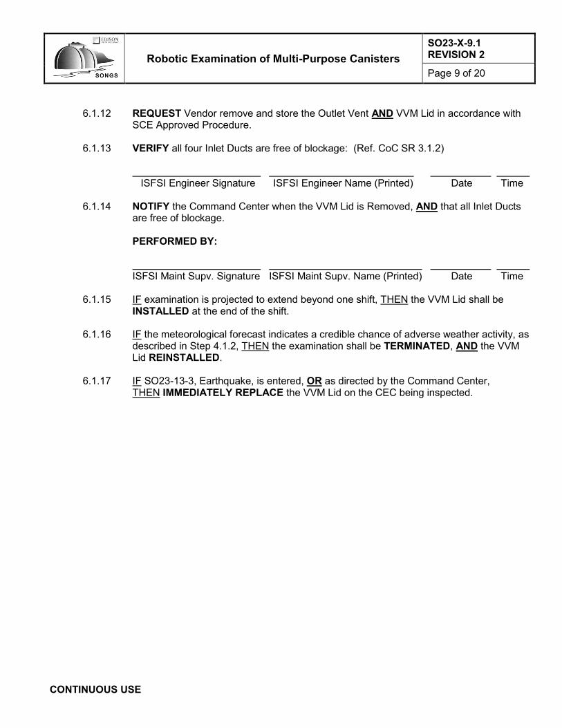
Robotic Examination of Multi-Purpose Canisters
SO23-X-9.1 REVISION 2
Page 9 of 20
CONTINUOUS USE
6.1.12 REQUEST Vendor remove and store the Outlet Vent AND VVM Lid in accordance with
SCE Approved Procedure.
6.1.13 VERIFY all four Inlet Ducts are free of blockage: (Ref. CoC SR 3.1.2)
ISFSI Engineer Signature ISFSI Engineer Name (Printed) Date Time
6.1.14 NOTIFY the Command Center when the VVM Lid is Removed, AND that all Inlet Ducts
are free of blockage.
PERFORMED BY: ISFSI Maint Supv. Signature ISFSI Maint Supv. Name (Printed) Date Time
6.1.15 IF examination is projected to extend beyond one shift, THEN the VVM Lid shall be
INSTALLED at the end of the shift.
6.1.16 IF the meteorological forecast indicates a credible chance of adverse weather activity, as described in Step 4.1.2, THEN the examination shall be TERMINATED, AND the VVM Lid REINSTALLED.
6.1.17 IF SO23-13-3, Earthquake, is entered, OR as directed by the Command Center,
THEN IMMEDIATELY REPLACE the VVM Lid on the CEC being inspected.

Robotic Examination of Multi-Purpose Canisters
SO23-X-9.1 REVISION 2
Page 10 of 20
CONTINUOUS USE
6.2 Robotic Examination of MPC
6.2.1 ENSURE robotic examination is ready to proceed.
6.2.2 REQUEST ISFSI Engineering direct Robotic Examination Contractor to commence robotic examination, including but not limited to:
• Evidence of scratching of the canister surface, particularly on the length of the canister directly under any of the eight Upper Seismic Restraints and in the accessible areas of the eight Lower Seismic Restraints.
• General condition of the canister, looking for evidence of cracking, pitting, or corrosion.
6.2.2.1 ISFSI Engineering RECORD data as required.
6.2.2.1.1 IF any indications are found, THEN DOCUMENT on Attachment 2.
6.2.2.2 IF any condition occurs which impacts continued examination, OR the robot
experiences any unanticipated conditions, THEN REQUEST the Robotic Examination Contractor to remove the robot from the CEC opening AND:
• TERMINATE the examination
• CONTACT the Command Center to report the problem with the examination
• GENERATE an AR to investigate the cause and to generate corrective actions
6.2.3 WHEN examination is complete, THEN REMOVE the robot from the CEC opening.
6.2.3.1 NOTIFY the Command Center that examination is complete.

Robotic Examination of Multi-Purpose Canisters
SO23-X-9.1 REVISION 2
Page 11 of 20
CONTINUOUS USE
6.3 Restoration
NOTE
Sections 6.3 and 6.4 may be performed concurrently or in any order.
6.3.1 ENSURE NO signs of debris present in the CEC. (Ref. CoC SR 3.1.2)
VERIFIED BY: ISFSI Maint Supv. Signature ISFSI Maint Supv. Name (Printed) Date Time
6.3.1.1 OBTAIN peer check.
6.3.2 PERFORM a final FME closeout inspection per SDS-MA3-PCD-0004, Foreign Material
Exclusion (FME), System Cleanliness, and Seismic Controls, or other approved FME procedure.
VERIFIED BY: ISFSI Maint Supv. Signature ISFSI Maint Supv. Name (Printed) Date Time
6.3.3 REQUEST Qualified Vendor install the VVM Lid AND Outlet Vent in accordance with SCE Approved Procedure.
NOTE
Survey points should be at approximately 0, 90, 180, and 270 degrees around the circumference of the lid. See Attachment 2 for orientation.
6.3.4 AFTER the VVM Lid is installed, THEN REQUEST RP PERFORM total (neutron plus
gamma) dose rate radiation surveys at the following locations: (Ref. CoC Tech. Spec. 5.3)
• Top of VVM: A minimum of four dose rate measurements taken on the top of the VVM. These measurements shall be taken approximately 90 degrees apart around the circumference of the lid, approximately 18 inches radially inward from the edge of the lid.
• Outlet Vents of the VVM: A minimum of four dose rate measurements taken adjacent to the outlet vent duct screen of the VVM, approximately 90 degrees apart.
Survey PERFORMED BY:
RP Person Signature RP Person Name (Printed) Date

Robotic Examination of Multi-Purpose Canisters
SO23-X-9.1 REVISION 2
Page 12 of 20
CONTINUOUS USE
6.3.4.1 RECORD Survey Results:
TOP OF VVM SURVEY LOCATION LIMIT
0° 90° 180° 270° Total mrem/hr Total mrem/hr Total mrem/hr Total mrem/hr 0.6 mrem/hr
OUTLET VENT OF VVM SURVEY LOCATION LIMIT
0° 90° 180° 270° Total mrem/hr Total mrem/hr Total mrem/hr Total mrem/hr 2.8 mrem/hr
6.3.4.1.1 Are all survey locations less than or equal to associated limit?
YES □ NO □
ISFSI Maint Supv. Signature ISFSI Maint Supv. Name (Printed) Date Time
6.3.5 WHEN the VVM Lid is installed, THEN NOTIFY the Command Center that the VVM Lid
has been installed.
PERFORMED BY: ISFSI Maint Supv. Signature ISFSI Maint Supv. Name (Printed) Date Time
NOTE
Steps 6.3.6 and 6.3.7 may be performed concurrently or in any order.
6.3.6 SCE Operations, PERFORM SO23-3-3.21.2, Defueled Surveillances, Attachment for
Defueled Shiftly Surveillance – Day Shift, Section for AHSM and VVM Temperature Monitoring, for VVM that had its Lid removed.
6.3.7 PERFORM an AS LEFT camera characterization system accuracy per Attachment 1.
(N/A if this is NOT the last MPC being inspected during this campaign.)

Robotic Examination of Multi-Purpose Canisters
SO23-X-9.1 REVISION 2
Page 13 of 20
INFORMATION USE
INFORMATION USE
6.4 Results
NOTE 1. Post-fabrication photographs are available for viewing from ISFSI
Engineering. 2. The canisters were inspected, photographed, and accepted prior to
leaving HOLTEC Manufacturing Division. 3. All examination data and pictures are the property of Southern California
Edison (SCE). 4. Sections 6.3 and 6.4 may be performed concurrently or in any order.
6.4.1 ISFSI Engineering AND the Robotic Examination Contractor shall IMMEDIATELY
REVIEW results of the examination.
6.4.1.1 COMPARE any indications found to the post-fabrication photographs taken of the canister. FOCUS on indications which were caused by loading and/or storage within the ISFSI Pad.
6.4.2 IF anomalies are noted in the examination results, THEN the ISFSI Engineer shall
IMMEDIATELY NOTIFY the Shift Manager.
6.4.2.1 The Shift Manager shall DETERMINE if an Operability Determination is required.
6.4.2.2 AFTER notifying the Shift Manager, THEN the ISFSI Engineer shall NOTIFY the ISFSI Engineering Manager.
6.4.2.3 The ISFSI Engineering Manager shall NOTIFY the Plant Manager regarding the
anomalies.
6.4.2.4 Before the end of shift, the ISFSI Engineer shall GENERATE an AR documenting the issue.
6.4.3 IF the result findings are consistent with the post-fabrication photographs, THEN within
two working days, the ISFSI Engineer shall GENERATE an AR Assignment to document the examination results.
6.4.4 CAPTURE examination photographs AND other pertinent data in an AR Assignment.

Robotic Examination of Multi-Purpose Canisters
SO23-X-9.1 REVISION 2
Page 14 of 20
INFORMATION USE
6.4.5 The Robotic Examination Contractor shall PROVIDE the removable storage device to
the ISFSI Engineer, or designee.
6.4.6 The Robotic Examination Contractor shall ENSURE that all examination data has been REMOVED from ALL Contractor cameras and/or Contractor owned storage devices.
Contractor Signature Contractor Name (Printed) Date
VERIFIED BY:
ISFSI Engineer Signature ISFSI Engineer Name (Printed) Date
6.4.7 WHEN data is no longer needed to be stored on the SCE removable storage device,
THEN ISFSI Engineering will COORDINATE with Cybersecurity to delete the information from the removable storage device.
Robotic Examination of Multi-Purpose Canisters
SO23-X-9.1 REVISION 2
Page 15 of 20
INFORMATION USE
7.0 ACCEPTANCE CRITERIA
7.1.1 None
8.0 RETENTION OF RECORDS 8.1 SCAN a copy of this procedure into eDMRM in accordance with RPA 04-0023E. 8.2 ATTACH a completed original of this procedure, and all supporting procedures and work
documents to the completed Work Order.
9.0 REFERENCES / COMMITMENTS 9.1 Implementing Reference
9.1.1 Commitments
9.1.1.1 1814-AR171-C0040, Certificate of Compliance (CoC) No. 72-1040 Appendix A Technical Specifications for HI-STORM UMAX Canister Storage System
9.1.1.1.1 CoC Tech. Spec. LCO 3.1.2, SFSC Heat Removal System
9.1.1.1.2 CoC Tech. Spec. 5.3, Radiation Protection Program
9.1.2 Procedures
9.1.2.1 SDS-MA3-PCD-0004, Foreign Material Exclusion (FME), System Cleanliness, and
Seismic Controls
9.1.2.2 SDS-RP2-PGM-2000, Radiological Work Planning and Controls
9.1.2.3 SDS-SH1-WIN-0017, Hazard Assessment and Pre-job Brief
9.1.2.4 SO123-XV-HU-3, Human Performance Program
9.1.2.5 SO123-VIII-ADMIN-1, Emergency Preparedness Program Maintenance
9.1.2.6 SO23-3-3.21.2, Defueled Surveillances
9.1.2.7 SO23-13-3, Earthquake 9.2 Developmental References
9.2.1 Response to Request for Technical Information (RRTI) Number 2464-038R1, Dated 2/19/2018, Summary: Convective heat removal with the VVM Lid removed is similar to the normal storage condition and is bounded by the normal long-term storage condition of the UMAX system with CEC lid presented in the FSAR

Robotic Examination of Multi-Purpose Canisters
SO23-X-9.1 REVISION 2
Page 16 of 20
Camera Characterization System Accuracy Attachment 1
INFORMATION USE Attachment 1 Page 1 of 2
1.0 Obtain the following from the calibration certificate for the GE Borescope:
GE Borescope Model / Serial Number:
Calibration Date:
Calibration Due Date:
Accepted by / Date: /
Type of Test: ☐ AS FOUND ☐ AS LEFT
2.0 Using the GE-supplied verification block with known width and depth, MEASURE width and depth
using the GE Borescope:
Verification Block Serial Number:
Calibration Date:
Calibration Due Date:
Accepted by / Date: /
Known Value Width Depth Delta
Target A: 0.100”
Target B: 1.00 mm
Performed by / Date: /
Accepted by / Date: /

Robotic Examination of Multi-Purpose Canisters
SO23-X-9.1 REVISION 2
Page 17 of 20
Camera Characterization System Accuracy Attachment 1
INFORMATION USE Attachment 1 Page 2 of 2
3.0 Use the GE Borescope to MEASURE depth between NIST-traceable 0.01” gauge blocks M&TE
number M5-0021 (ID #172253) AND M5-0022 (ID #172308), placed parallel upon a flat surface. The surface should be NIST-traceable, if available:
NIST traceable Surface Plate Number: (Mark N/A if unavailable.)
Known Value Depth Delta
0.01”
Performed by / Date: /
Accepted by / Date: /
4.0 The deltas recorded in Steps 2.0 and 3.0 represent measurement uncertainty for the examination.

Robotic Examination of Multi-Purpose Canisters
SO23-X-9.1 REVISION 2
Page 18 of 20
Indication List and Location Identifier Attachment 2
INFORMATION USE Attachment 2 Page 1 of 2
Pad Location Identifier Pad Location Number: MPC Serial Number:
NOTE
1. Top of MPC is above top of MPC inner Seismic Restraints. 2. Zero degrees faces North. 3. Field markings for 90 degrees and 270 degrees do NOT match fabrication
the Fabrication Drawings (off by 180 degrees). Use Figure 1 compass markings and Quadrant numbering.
IF any indications are identified, THEN ENTER information in the following table, AND MARKUP Figure 1 to show the location of the indication using the number from the following table. Indication Identifier
Indication Quadrant Angle to Adj Quadrant / Object Identifier
Elevation L x W x D (max/mult)
1
2
3
4
5
6
7
8
9
10
11
12
13
14
15

Robotic Examination of Multi-Purpose Canisters
SO23-X-9.1 REVISION 2
Page 19 of 20
Indication List and Location Identifier Attachment 2
INFORMATION USE Attachment 2 Page 2 of 2
Figure 1
NORTH
NORTH
Top of MPC

Robotic Examination of Multi-Purpose Canisters
SO23-X-9.1 REVISION 2
Page 20 of 20
Summary of Changes Attachment 3
INFORMATION USE Attachment 3 Page 1 of 1
Author: Frank Grovich
Reason Description of Change Reviewer(s) (by title or division)
50.59/ 72.48
Step, Section, Attachment
or Page
0419-55062 Added step to request permission to remove Outlet Vents to allow access to VVM Lid being removed. Clarified that removal of the VVM Lid includes removal of the Outlet Vent.
All A 8
Required Reviewers Name
Emergency Plan 50.54(q) DNA
Physical Security Plan 50.54(p) DNA
Fire Protection 50.48(f) DNA
50.59 DNA
72.48 APPLIES (Screen not required, see above)
Cyber Security APPLIES Marc Rice
Nuclear Oversight APPLIES Reviews at Approval (see below)
Procedure Owner or designee Allen Williams
Other Reviewers
Operations Mike Powell
Maintenance John Patterson
Maintenance Mike Orewyler
Approvers:
Cognizant Supervisor N/A for Revision
Nuclear Oversight Final C. Vanderniet
CFDM / Designee Final Jerry Stephenson

Exhibit 4

SONGS Downloading Effects on HI-STORM MPC Visual Assessment Report
SOUTHERN CALIFORNIA EDISON An EDISON INTERNATIONAL Company
SAN ONOFRE NUCLEAR GENERATING STATION DOWNLOADING EFFECTS ON HI-STORM MPC
VISUAL ASSESSMENT REPORT April 15, 2019

SONGS Downloading Effects on HI-STORM MPC Visual Assessment Report
Page 1
Record of Revision
Revision No.
Pages/Sections/ Paragraphs Changed Brief Description / Change Authorized
0 Entire Document Initial Issue
CC: RPA 04-0023E

SONGS Downloading Effects on HI-STORM MPC Visual Assessment Report
Page 3
1.0 INTRODUCTION San Onofre Nuclear Generating Station (SONGS) performed a visual assessment of eight multi-purpose canisters (MPCs) from March 21 – 23 and April 9 – 13, 2019. The NRC was present for the majority of the MPC visual assessments. This report includes the following:
Scope of visual assessments Visual assessment techniques utilized Visual assessment results Conclusion
2.0 VISUAL ASSESSMENT SCOPE The scope of the visual assessment is the accessible surfaces of the MPC shell and baseplate. The eight MPCs included were selected for the following reasons: 1) MPC serial number (S/N) 067 was involved in the Aug. 3, 2018, event when it was wedged on the divider shell shield ring; 2) MPC S/N 064 was documented as having made contact with the divider shell on July 22, 2018, during downloading operations; and 3) the remaining six MPCs are located on different rows than the previous two MPCs. Different rows were selected to account for the drainage slope on the HOLTEC ISFSI pad and its potential effect on MPC vertical alignment during downloading operations. The MPCs selected were downloaded at varying times in the fuel transfer operation campaign. Due to allowable tolerances in the manufacturing process each MPC and pad location is unique. See Appendix A for a map of the Holtec ISFSI pad locations included in the visual assessment. A third party statistical evaluation was performed based on the maximum wear mark depth observed for each MPC. A projection of an upper tolerance limit based on wear mark depth was established. Based on the results for the eight MPCs, this sample size yields a 95 percent probability, with 95 percent confidence level, that wear marks would not be deeper than 0.035 inches. This maximum depth remains in compliance with all applicable ASME Boiler & Pressure Vessel Code requirements. 3.0 VISUAL ASSESSMENT TECHNIQUES A robotic crawler equipped with navigational cameras and a borescope, a flexible camera with interchangeable tips (general area tip and measurement tip), was deployed in two stages to perform the visual assessment. During the first stage, the robotic crawler and borescope with the general area tip was used to identify general locations of surface irregularities. During the second stage, the robotic crawler with the borescope using the measurement tip characterized the surface irregularities (width and depth measurements as applicable). Surface irregularities were compared to post-fabrication photos to determine if the irregularities were present prior to MPC downloading. The General Electric (GE) borescope (i.e., VideoProbe™), along with the Robotic Technologies of Tennessee (RTT) robot, were selected by EPRI’s Extended Storage Collaboration Program (ESCP) NDE subcommittee, which was tasked with developing technology to support inspecting dry storage canisters. The robot and borescope have been deployed at multiple U.S. nuclear sites, most recently at Vermont Yankee and Maine Yankee. The NRC has been present during many of these inspections. The Maine Yankee inspection was performed to support renewal of NAC CoCs 72-1015 (NAC-UMS) and 72-1025 (NAC-MPC). GE Inspection Technologies’ VideoProbe, with Real3D™ point cloud surface scanning and analysis, is used widely for aviation, military, and oil & gas applications. On a daily basis, there are hundreds of technicians globally using the technology to ensure airplanes are safe to fly, and turbines are safe to operate. See Appendix C for details regarding calibration and certification.

SONGS Downloading Effects on HI-STORM MPC Visual Assessment Report
Page 4
4.0 VISUAL ASSESSMENT RESULTS The following surface irregularities associated with downloading operations were found:
Wear marks Free iron transfer in a local surface film on the MPC – exhibited by iron oxide staining
All surface irregularities were compared to post-fabrication photos taken at Holtec Manufacturing Division prior to being shipped to SONGS. This comparison was used to assist in determining whether the surface irregularities were a result of downloading operations. All surface irregularities identified on post-fabrication photos were previously evaluated and deemed acceptable prior to shipping to SONGS. Surface irregularities that were not consistent with post-fabrication photos were documented in completed visual assessment procedures. Of those surface irregularities, areas of interest were identified to undergo characterization (width and depth measurements as applicable). A few of the identified areas of interest crossed over or reside within the weld and heat affected zones (HAZs) of the circumferential weld. All welds and HAZs with the potential to make incidental contact during downloading operations had a protective peened layer applied during manufacturing. Table 1 below provides characterization measurements for areas of interest associated with downloading operations. See Appendix B for figures that provide reference information for the HI-STORM UMAX vertical ventilated module (VVM). The majority of wear marks identified are correlated with contact with the divider shell shield ring and had maximum wear depths up to 0.012 inches deep. Additional wear marks identified are correlated with contact with one of the MPC inner seismic restraints, also referred to as the upper seismic restraints, and had maximum wear depths up to 0.026 inches deep. The divider shell shield ring is constructed out of carbon steel with a protective coating and incidental contact with the MPC has led in some cases to locally rubbing off the coating and free iron transfer as exhibited by iron oxide staining in wear marks on some MPCs. The MPC inner seismic restraints are constructed out of stainless steel and pose no risk of incidental contact leading to free iron transfer onto the MPCs. Free iron transfer and iron oxide staining will be considered as part of the aging management program Wear profiles for divider shell shield ring and MPC inner seismic restraints are different. The divider shell shield ring wear marks are broader and shallower in comparison. The maximum depth caused by an MPC inner seismic restraint occurred over a relatively short length in a localized narrow area and does not apply over the entire length and width of the wear mark.

SONGS Downloading Effects on HI-STORM MPC Visual Assessment Report
Page 5
TABLE 1 – DOWNLOADING OPERATIONS AREA OF INTEREST CHARACTERIZATION
MPC S/N
Description Circumferential
Location3 Length1 (inches)
Width2 (inches)
Maximum Depth2 (inches)
067 No areas of interest from downloading operations provided a measurable depth (all less than 0.001 inches)
064 Free Iron Transfer Between SR5 – SR6 30 2 0.012
064 Wear Mark Between SR5 – SR6 6 1 0.009
064 Wear Mark Between SR5 – SR6 6 1 0.009
064 Wear Mark Between SR5 – SR6 8 1 0.009
064 Wear Mark4 Between SR5 – SR6 1 4 0.009
064 Wear Mark Between SR6 – SR7 15 5 0.011
064 Wear Mark Between SR7 – SR8 30 2 0.003
072 Free Iron Transfer4 Between SR1 – SR2 4 8 < 0.001
072 Wear Mark Between SR1 – SR2 0.002 square inches5 0.007
072 Wear Mark4 Below SR1 > 120 ~ SR4 wear mark ~ SR4 wear mark
072 Wear Mark4 Below SR4 > 120 0.107 to 0.192 0.016
072 Wear Mark Below SR4 12-24 < 0.192 0.026
072 Wear Mark Below SR5 24-36 ~ SR4 wear mark ~ SR4 wear mark
094 Free Iron Transfer4 Between SR1 – SR2 4 8 0.012
055 Wear Mark Below SR2 6 0.25 0.003
055 Free Iron Transfer4 Between SR1 – SR2 6 4 0.004
055 Free Iron Transfer Between SR1 – SR2 8 0.5 0.005
055 Free Iron Transfer Between SR3 – SR4 6 0.125 0.003
055 Wear Mark4 Below SR5 > 130 0.25 0.012
055 Wear Mark4 Below SR6 > 120 0.25 0.004
065 Free Iron Transfer4 Between SR1 – SR2 4 8 < 0.001
065 Wear Mark Below SR3 > 130 < 0.2 0.011
065 Wear Mark Below SR7 12-24 < 0.2 0.002
068 Free Iron Transfer4 Between SR1 – SR2 3 6 < 0.001
068 Wear Mark Below SR3 200 0.25 – 0.75 0.004
061 Free Iron Transfer4 Between SR1 – SR2 4 8 < 0.001
061 Wear Mark Below SR2 > 60 0.125 0.001
061 Wear Mark Below SR3 > 60 0.125 0.012
Notes: 1) Length measurements are approximate values based on the general area visual assessment. 2) Width and depth measurements characterized during the area of interest visual assessment. 3) See Appendix B for VVM reference information.
4) Area of interest resides within the weld and/or HAZ. 5) A direct surface area measurement was recorded. The results of the visual assessment have been entered into the corrective action program and will be considered as part of the aging management program.

SONGS Downloading Effects on HI-STORM MPC Visual Assessment Report
Page 6
5.0 CONCLUSION Eight MPCs underwent visual assessments where various types of surface irregularities were identified. The deepest surface irregularity identified as a result of downloading operations was a wear mark due to contact with an MPC inner seismic restraint. The maximum depth of 0.026 inches existed in a localized narrow area and did not apply over the entire length and width of the wear mark. Based on statistical assessment of the data, any wear mark that might occur during downloading operations has a 95 percent probability, with a 95 percent confidence level, of having an upper bound depth of 0.035 inches. This provides adequate assurance that any wear mark that might occur during downloading operations would be in compliance with all applicable ASME Boiler & Pressure Vessel Code requirements. 6.0 LIST OF APPENDICES
A. Holtec ISFSI Pad Location and Visual Assessment Scope Map B. Holtec HI-STORM UMAX Vertical Ventilated Module (VVM) Reference Information C. Description of GE Technologies Calibrations and Certifications

SONGS Downloading Effects on HI-STORM MPC Visual Assessment Report
Page A-1
Appendix A Holtec ISFSI Pad Location and Visual Assessment Scope Map

SONGS Downloading Effects on HI-STORM MPC Visual Assessment Report
Page B-1
Appendix B Holtec HI-STORM UMAX Vertical Ventilated Module (VVM) Reference Locations

SONGS Downloading Effects on HI-STORM MPC Visual Assessment Report
Page B-2
List of Potential Contact Points 1 Divider Shell Shield Ring Guide 2 Divider Shell Shield Ring 3 MPC Inner Seismic Restraint (also referred to as upper seismic restraint) 4 Divider Shell MPC Guide Cover 5 Lower MPC Guide / CEC Baffle Plate (also referred to as lower seismic restraint)

SONGS Downloading Effects on HI-STORM MPC Visual Assessment Report
Page C-1
Appendix C Description of GE Technologies Calibrations and Certifications
GE Inspection Technologies’ VideoProbe manufacturing facility is in Skaneateles, NY; this is an ISO 9001:2015 certified facility. All calibrations for all measurement-capable VideoProbes, and the related measurement accessories, are calibrated to NIST-traceable standards under GE’s ISO 9001:2015 procedures. SCE confirmed the GE inspectors’ Level II visual inspection certification, and that their certification was current. A corresponding “encode” was created in SONGS training program, which was used to confirm the GE inspectors were qualified to perform the borescope inspections (procedure requirement). SONGS QA program requirements were applied to inspection activities, including developing and issuing the inspection procedure, calibration verification, and documentation of results. To verify a VideoProbe is in calibration for all measurement types, an NIST-traceable Verification Block ships with all measurement probes and the tips calibrated to that probe:
A Certificate of Calibration is created for each probe(s) and the tip(s) calibrated to a given probe, as well as for all Verification Blocks.
The Verification Block is an NIST-traceable standard with precise targets. The A target has two (2) distance targets with a separation of 0.1000 in. +/- .0002 in. The B target has a distance separation of 1.000mm +/- .005mm. The standard’s characteristics were optimized for length measurements (x, y), and is not intended to
be used as a depth (z) standard. With Real3D, it is the plurality of the x, y, z data that is used to generate a point cloud of data on
which measurements are made. Thus, the Verification Blocks’ targets also verify a system is in calibration for use in measuring
Depths, Lengths, and Areas. To provide additional assurance of depth measurement capabilities, SCE procured NIST-traceable gauge blocks. Two gauge blocks were placed parallel to each other, upon a NIST-traceable flat surface plate, with a small gap between the two blocks that are 0.010 inches ± 2.0 µ inches thick. The VideoProbe correctly measured the height of the gauge blocks (space between the two blocks) to the nearest 0.001 ± 0.0005 inches. Two MPC inspection campaigns were performed. The first campaign was performed on March 21-23, 2019 and included three MPCs. The second campaign was performed on April 9-13, 2019 and included five MPCs. As documented in SCE procedure SO23-X-9.1, Robotic Inspection of Multi-Purpose Canisters, the depth measurement function was verified prior to use on the first canister of each campaign, using the GE-supplied targets and SCE-supplied gauge blocks. This verification was performed again after completing inspection of the final canister of each campaign.

Exhibit 5

Prior history of
documented SCC on similar canisters
Perform inspection of twoHoltec UMAX canisters,starting in 2024 (Note 1)
SCREENING INSPECTIONVT-3 Visual
Examination of all accessible surfaces
Decrease inspection interval to 30 months, or to less than limiting
flaw growth time,whichever is less.
Classify anomaliesaccording to mostsevere corrosionlevel and location
(Note 4)
Any corrosion in weld region
of canister
Visual Anomalies
Discovered?(Note 2)
AnomaliesConsistent with
Prior Results(Note 3)
Evidence of SCC or
evaluation concludesSCC llikely?
ASSESSMENT INSPECTIONPerform VT-1 Visual
Examination of canister with‘inconsistent anomalies’
SUPPLEMENTAL INSPECTIONPerform surface or volumetricexaminations (UT, ECT, etc.).
Majorcorrosionaway fromweld region
Insignificant or minor corrosion
away fromweld region
Initiate CorrectiveAction Document
Record inspectionresults andmaintain records
Prepare inspectionreport
Maintain current
inspection interval and population
Perform appropriate
evaluation to determine if mitigation is needed (meets I&M
plan mitigation options)
Perform mitigation of
affected areas
Decreaseinspection
interval to 30months
SCOPE EXPANSION
Perform exams (at a minimum,screening inspection followed byassessment and supplementalinspections if required by this flowchart)or one additional canister from the setof most vulnerable canisters. If thescope has already been expanded once,and the expanded sample also has SCC,then examine additional canisters.
FLAW EVALUATION
Size flaw using volumetric techniques or evaluation
Assume a limiting degradation growth rate based on site-specific observations or industrywide data
Calculate time to reach limiting flaw size
START OF I&M PLAN
SONGS IMP – INSPECTION AND REMEDIATION FLOWCHART
NOTE 1: Inspect one specific canister each inspection interval. Select the second canister based on potential SCC susceptibility per EPRI susceptibil-ity report.
NOTE 2: Visual anomalies are defined in DRAFT N-860 Code Case (ID -2221) and summarized below:
1) Surface discontinuities (wear, gouges, dents, surface irregularities). These surface discontinuities do not include standard, normal, or expected surface discontinuities which result from normal fabrication or loading practices.
2) Corrosion or corrosion products (discoloration, cracking, pitting, oxides, crud).
3) Flaw indications (cracking, pitting).
4) Loose, missing, distorted, displaced, cracked, fractured, or damaged systems, structures, or compounds.
NOTE 3: Prior results are those records captured during previous I&M Plan examinations, using equivalent methodsand techniques. ‘Consistent’ means identical in size, location, and distribution. Other Holtec UMAX anomalies consistent with prior inspection results are not considered to be new anomalies.
NOTE 4: ‘Most severe corrosion level’ is defined in DRAFT N-860 Code Case (ID -2321) and classified as ’Major’, ‘Minor’, or ‘Insignificant.
NO
NO
NO
NO
NO
YES
YES YES
YES
YES

Exhibit 6

Robotic Mitigation of Multi-Purpose Canisters
SO23-X-9.2 REVISION 0
Page 1 of 22
QA PROGRAM AFFECTING
Procedure Type Procedure Owner
Engineering Jerry Stephenson
INFORMATION USE
Procedure Usage Requirements Sections
Information Use • The user may complete the task from memory; however, the user is responsible for performing the activity according to the procedure.
• Information use documents that contain a specific process order are performed in the given order unless otherwise specified within the document
Sections 1.0 through 5.0,
Section 6.7 and 6.8, Sections 7.0
through 9.0 and Attachment 1, 2, and 3
Continuous Use • Review and understand the document before performing any steps, including the precautions, limitations, and prerequisite sections.
• Have a copy or applicable pages in direct or immediate possession or be in direct communication with someone who has a copy in hand.
• Use Placekeeping method according to SO123-XV-HU-3.
• Read and understand each step before performing it.
• Complete each step before starting the next step.
• Review and placekeep each step after completion to ensure the step was performed correctly.
• Perform the step as written in the sequence specified, except when an approved process specifically allows deviation
Sections 6.1 through 6.6

Robotic Mitigation of Multi-Purpose Canisters
SO23-X-9.2 REVISION 0
Page 2 of 22
INFORMATION USE
TABLE OF CONTENTS
Section Page
1.0 PURPOSE AND SCOPE ................................................................................................................ 3
2.0 RESPONSIBILITIES ....................................................................................................................... 3
3.0 DEFINITIONS ................................................................................................................................. 4
4.0 PRECAUTIONS AND LIMITATIONS .............................................................................................. 4
5.0 PREREQUISITES ........................................................................................................................... 5
6.0 PROCEDURE ................................................................................................................................. 6 6.1 Pre-Test ............................................................................................................................... 6 6.2 Removing VVM Lid .............................................................................................................. 6 6.3 Pre-Mitigation Robotic Examination of Test Canister ........................................................... 7 6.4 Performing Mitigation Activities on the Test Canister ........................................................... 8 6.5 Post Mitigation Robotic Examination of Test Canister .......................................................... 9 6.6 Restoration ........................................................................................................................ 10 6.7 Robotic Examination Results ............................................................................................. 11 6.8 Mitigation Activities Results ............................................................................................... 12
7.0 ACCEPTANCE CRITERIA ............................................................................................................ 13
8.0 RETENTION OF RECORDS ......................................................................................................... 13
9.0 REFERENCES / COMMITMENTS ................................................................................................ 14 ATTACHMENT 1 Mitigation Data .............................................................................................................................. 15 2 Camera Characterization System Accuracy .................................................................................. 19 3 Summary of Changes .................................................................................................................... 21
Robotic Mitigation of Multi-Purpose Canisters
SO23-X-9.2 REVISION 0
Page 3 of 22
INFORMATION USE
1.0 PURPOSE AND SCOPE 1.1 Purpose
NOTE
Robotic examination and characterization of scratches or gouges may be limited to pre-determined locations on the Test Multi-Purpose Canister (MPC).
1.1.1 Perform a robotic examination of pre-determined locations on the Test Multi-Purpose
Canister (MPC) stored in a Vertical Ventilation Module (VVM).
1.1.2 Perform characterization of any scratches or gouges of the Test Multi-Purpose Canister (MPC).
1.1.3 Perform robotic mitigation activities on the Test Multi-Purpose Canister (MPC), stored in
a Vertical Ventilation Module (VVM). 1.2 Scope
1.2.1 The Scope of the mitigation activities is for accessible surfaces of the Test MPC shell and baseplate.
2.0 RESPONSIBILITIES 2.1 A Qualified ISFSI Maintenance Supervisor is responsible for coordinating and directing the actions
of the evolution per this procedure. 2.2 ISFSI Maintenance Supervisor is responsible for coordination of the work packages associated with
the MPC mitigation activities, along with providing guidance related to Foreign Materials Exclusion (FME) Controls to support the MPC mitigation activities.

Robotic Mitigation of Multi-Purpose Canisters
SO23-X-9.2 REVISION 0
Page 4 of 22
INFORMATION USE
2.3 ISFSI Engineering is responsible for all coordination with the Contractor performing mitigation
activities.
2.3.1 Results of the mitigation activities are reviewed by ISFSI Engineering.
2.3.2 Data may be shared with contractors and other outside Consulting Agencies involved in the mitigation activities with PRIOR approval of the ISFSI Engineering Manager.
2.3.2.1.1 Contractors and outside Consulting Agencies must sign a non-disclosure
agreement. 2.4 SCE Maintenance is responsible for preparations for VVM Lid removal and installation. 2.5 SCE Security is responsible for control of all access and egress activities into the ISFSI Protected
Area.
3.0 DEFINITIONS
Mitigation The process developed by SCE (and Contractors) which is deployed to perform a non-structural repair on a degraded Holtec Multi-Purpose Canister.
4.0 PRECAUTIONS AND LIMITATIONS 4.1 Precautions
4.1.1 The HI-STORM UMAX lid (VVM Lid) shall NOT be removed during inclement weather if the meteorological forecast indicates a credible chance of adverse weather activity such as lightning, snow fall, rain, or heavy winds at the ISFSI during the planned examination. Inclement weather includes:
• Lightning: Signs of an approaching thunderstorm or the sound of thunder, even distant.
• Rain: Greater than 0.30 in./hour rain at a 60% or greater probability as forecasted by the National Weather Service Quantitative Precipitation Forecast and Probability of Precipitation for Orange County.
• Heavy winds: Anticipated wind speed of 30 mph or greater.

Robotic Mitigation of Multi-Purpose Canisters
SO23-X-9.2 REVISION 0
Page 5 of 22
INFORMATION USE
5.0 PREREQUISITES 5.1 VERIFY this document is current by using one of the methods described in SO123-XV-HU-3. 5.2 VERIFY Level of Use requirements on the first page of this procedure. 5.3 ENSURE ALL mitigation equipment pre-tests have been completed, AND ALL equipment is within
calibration requirements. 5.4 ENSURE the following:
• ALL contractor tooling staged
• Temporary power for examination equipment is available
• Work/laydown areas established
• FME area tape and signs staged/ready 5.5 All personnel must be trained and have their qualifications verified in order to perform operations in
this procedure.
5.5.1 At least one member of the work group has the following qualifications:
• 3RCVIL2, Robotic Camera Visual Inspection (Vendor Training/Certification)
• 3MRISTC, Mobile Robotic Inspection Technician (Vendor Training/Certification)
• 3MOTVEN, Metallic Overlay Technician (required for mitigation activities, not required for MPC examinations)
5.5.2 The ISFSI Maintenance Supervisor has the following qualification:
• 4MANMD, Multi-Discipline Maintenance Supervisor 5.6 BRIEF the Command Center on the mitigation activities on the MPC.
Items to consider during brief (not a complete list):
• Person in charge of the overall evolution and how to contact this person
• Person in charge of specific portions of the evolution, if required, e.g., ISFSI Maintenance Supervisor for VVM Lid Removal
• Notifying the Command Center if unexpected issues arise which differ from the discussed plan

Robotic Mitigation of Multi-Purpose Canisters
SO23-X-9.2 REVISION 0
Page 6 of 22
CONTINUOUS USE
CONTINUOUS USE
6.0 PROCEDURE
6.1 Pre-Test (May be performed at any time prior to actual mitigation.) 6.1.1 PERFORM Pre-Testing on mitigation system using a mockup fixture.
6.1.1.1 Vendor’s process control parameters were maintained throughout the testing:
VERIFIED BY:
ISFSI Maint Supv. Signature ISFSI Maint Supv. Name (Printed) Date Time
6.2 Removing VVM Lid
6.2.1 VERIFY meteorological forecast indicates that weather conditions for the expected duration of work will not be affected by the restrictions of Step 4.1.1.
6.2.2 PERFORM a Pre-Job Brief and Job Safety Analysis with all personnel involved with the
mitigation activities. Due to differing work hours and potential shift changes, multiple Pre-Job Briefs and Job Safety Analyses may be performed to ensure all personnel are briefed.
NOTE
Steps 6.2.3 through 6.2.5 may be performed concurrently or in any order.
6.2.3 ENSURE an AS FOUND camera characterization system accuracy has been validated
per Attachment 2. (May be performed concurrently with remainder of Section 6.2.)
6.2.4 PERFORM a pre-inspection of the area around the VVM Lid and the VCT (or other VVM Lid lifting device) for loose materials that may fall into the open CEC.
6.2.4.1 REMOVE any loose material which has the potential for falling into the open CEC.
6.2.5 ESTABLISH a FME area around the CEC opening per SDS-MA3-PCD-0004, Foreign
Material Exclusion (FME), System Cleanliness, and Seismic Controls.
6.2.6 REMOVE AND STORE the Outlet Vent AND VVM Lid.
6.2.7 IF the meteorological forecast indicates a credible chance of adverse weather activity, as described in Step 4.1.1, THEN the mitigation activities shall be TERMINATED, AND the mitigation equipment shall be REMOVED, AND VVM Lid REINSTALLED.
6.2.8 IF directed by the Command Center, THEN IMMEDIATELY REMOVE the mitigation
equipment, AND REPLACE the VVM Lid on the CEC being mitigated.

Robotic Mitigation of Multi-Purpose Canisters
SO23-X-9.2 REVISION 0
Page 7 of 22
CONTINUOUS USE
6.3 Pre-Mitigation Robotic Examination of Test Canister
6.3.1 ENSURE robotic examination is ready to proceed.
6.3.2 REQUEST ISFSI Engineering direct Robotic Examination Contractor to commence robotic examination of pre-determined area(s) of the Test.
6.3.2.1 ISFSI Engineering RECORD data as required.
6.3.2.1.1 IF any indications are found, THEN DOCUMENT on Attachment 1.
6.3.2.2 IF any condition occurs which impacts continued examination, OR the robot
experiences any unanticipated conditions, THEN REQUEST the Robotic Examination Contractor to remove the robot from the CEC opening AND:
• TERMINATE the examination
• CONTACT the Command Center to report the problem with the examination
• GENERATE an AR to investigate the cause and to generate corrective actions
6.3.3 IF examination activities are complete for the day, AND examination OR mitigation activities will recommence the following work day, THEN INFORM the Command Center of the status of the mitigation activities.
6.3.4 WHEN examination is complete, THEN REMOVE the robot from the CEC opening.
6.3.5 REVIEW results of the examination per Section 6.7.

Robotic Mitigation of Multi-Purpose Canisters
SO23-X-9.2 REVISION 0
Page 8 of 22
CONTINUOUS USE
6.4 Performing Mitigation Activities on the Test Canister
6.4.1 ENSURE mitigation activities are ready to proceed.
6.4.2 REQUEST ISFSI Engineering to direct Contractor to commence mitigation activities per VRC Metal Systems Supersonic Metal Particle Overlay for Spent Fuel Canister Mitigation A004 - Application Process Operating Instruction.
6.4.2.1 ISFSI Engineering RECORD data as required.
6.4.2.2 IF any condition occurs which impacts continued mitigation, OR the robot experiences
any unanticipated conditions, THEN REQUEST the Contractor to remove the mitigation equipment from the CEC opening AND:
• TERMINATE the mitigation activities
• CONTACT the Command Center to report the problem with the mitigation activities
• GENERATE an AR to investigate the cause and to generate corrective actions
6.4.3 IF mitigation activities are complete for the day, AND mitigation or evaluation activities will recommence the following work day, THEN INFORM the Command Center of the status of the mitigation activities.
6.4.4 WHEN mitigation activities are complete, THEN REMOVE the mitigation equipment from
the CEC opening.
6.4.5 DOCUMENT mitigation areas and work performed in Attachment 1.
6.4.6 NOTIFY the Command Center that mitigation activities are complete, AND ALL mitigation equipment has been removed from the CEC Opening.
6.4.7 PERFORM Post Testing on mitigation system using a mockup fixture.
(May be performed concurrently with remainder of procedure.)
6.4.7.1 Vendor’s process control parameters were maintained throughout the testing: VERIFIED BY:
ISFSI Maint Supv. Signature ISFSI Maint Supv. Name (Printed) Date Time

Robotic Mitigation of Multi-Purpose Canisters
SO23-X-9.2 REVISION 0
Page 9 of 22
CONTINUOUS USE
6.5 Post Mitigation Robotic Examination of Test Canister
6.5.1 ENSURE robotic examination is ready to proceed.
6.5.2 REQUEST ISFSI Engineering direct Robotic Examination Contractor to commence robotic examination of the mitigated area(s) of the Test Canister.
6.5.2.1 ISFSI Engineering RECORD data as required.
6.5.2.1.1 DOCUMENT on Attachment 1.
6.5.2.2 IF any condition occurs which impacts continued examination, OR the robot
experiences any unanticipated conditions, THEN REQUEST the Robotic Examination Contractor to remove the robot from the CEC opening AND:
• TERMINATE the examination
• CONTACT the Command Center to report the problem with the examination
• GENERATE an AR to investigate the cause and to generate corrective actions
6.5.3 IF examination activities are complete for the day, AND examination OR mitigation activities will recommence the following work day, THEN INFORM the Command Center of the status of the mitigation activities.
6.5.4 WHEN examination is complete, THEN REMOVE the robot from the CEC opening.
6.5.5 REVIEW results of the examination per Section 6.7.
6.5.6 PERFORM an AS LEFT camera characterization system accuracy per Attachment 2.
(May be performed concurrently with Section 6.6.)

Robotic Mitigation of Multi-Purpose Canisters
SO23-X-9.2 REVISION 0
Page 10 of 22
CONTINUOUS USE
6.6 Restoration
NOTE
Sections 6.6, 6.7, and 6.8 may be performed concurrently or in any order.
6.6.1 ENSURE NO signs of debris present in the CEC. (Ref. CoC SR 3.1.2)
VERIFIED BY: ISFSI Maint Supv. Signature ISFSI Maint Supv. Name (Printed) Date Time
6.6.1.1 OBTAIN peer check.
6.6.2 PERFORM a final FME closeout inspection per SDS-MA3-PCD-0004, Foreign Material
Exclusion (FME), System Cleanliness, and Seismic Controls.
VERIFIED BY: ISFSI Maint Supv. Signature ISFSI Maint Supv. Name (Printed) Date Time
6.6.3 INSTALL the VVM Lid AND Outlet Vent.
6.6.4 WHEN the VVM Lid is installed, THEN NOTIFY the Command Center that the VVM Lid has been installed.
PERFORMED BY: ISFSI Maint Supv. Signature ISFSI Maint Supv. Name (Printed) Date Time
6.6.5 PERFORM any required mitigation equipment post tests.

Robotic Mitigation of Multi-Purpose Canisters
SO23-X-9.2 REVISION 0
Page 11 of 22
INFORMATION USE
INFORMATION USE
6.7 Robotic Examination Results
NOTE 1. Post-fabrication photographs are available for viewing from ISFSI
Engineering. 2. The canisters were inspected, photographed, and accepted prior to
leaving HOLTEC Manufacturing Division. 3. All examination data and pictures are the property of Southern California
Edison (SCE). 4. For Post-Mitigation Examination Results Sections 6.6 and 6.7 may be
performed concurrently or in any order.
6.7.1 ISFSI Engineering AND the Robotic Examination Contractor shall IMMEDIATELY
REVIEW results of the examination.
6.7.1.1 For Pre-Mitigation Examination Results: COMPARE any indications found to the post-fabrication photographs taken of the canister.
6.7.1.2 For Post-Mitigation Examination Results: COMPARE any indications found to the
post-fabrication and/or the Pre-Mitigation photographs taken of the canister.
6.7.2 IF anomalies are noted in the examination results, THEN before the end of shift, the ISFSI Engineer shall GENERATE an AR documenting the issue.
6.7.3 IF the result findings are consistent with the post-fabrication photographs, THEN within
two working days, the ISFSI Engineer shall GENERATE an AR Assignment to document the examination results.
6.7.4 CAPTURE examination photographs AND other pertinent data in an AR Assignment.
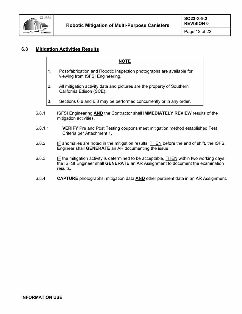
Robotic Mitigation of Multi-Purpose Canisters
SO23-X-9.2 REVISION 0
Page 12 of 22
INFORMATION USE
6.8 Mitigation Activities Results
NOTE 1. Post-fabrication and Robotic Inspection photographs are available for
viewing from ISFSI Engineering. 2. All mitigation activity data and pictures are the property of Southern
California Edison (SCE). 3. Sections 6.6 and 6.8 may be performed concurrently or in any order.
6.8.1 ISFSI Engineering AND the Contractor shall IMMEDIATELY REVIEW results of the
mitigation activities.
6.8.1.1 VERIFY Pre and Post Testing coupons meet mitigation method established Test Criteria per Attachment 1.
6.8.2 IF anomalies are noted in the mitigation results, THEN before the end of shift, the ISFSI
Engineer shall GENERATE an AR documenting the issue .
6.8.3 IF the mitigation activity is determined to be acceptable, THEN within two working days, the ISFSI Engineer shall GENERATE an AR Assignment to document the examination results.
6.8.4 CAPTURE photographs, mitigation data AND other pertinent data in an AR Assignment.
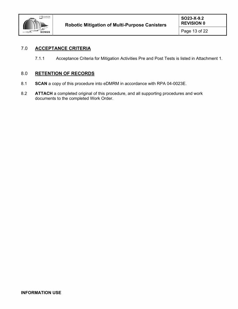
Robotic Mitigation of Multi-Purpose Canisters
SO23-X-9.2 REVISION 0
Page 13 of 22
INFORMATION USE
7.0 ACCEPTANCE CRITERIA
7.1.1 Acceptance Criteria for Mitigation Activities Pre and Post Tests is listed in Attachment 1.
8.0 RETENTION OF RECORDS 8.1 SCAN a copy of this procedure into eDMRM in accordance with RPA 04-0023E. 8.2 ATTACH a completed original of this procedure, and all supporting procedures and work
documents to the completed Work Order.

Robotic Mitigation of Multi-Purpose Canisters
SO23-X-9.2 REVISION 0
Page 14 of 22
INFORMATION USE
9.0 REFERENCES / COMMITMENTS 9.1 Implementing Reference
9.1.1 Commitments
9.1.1.1 1814-AR171-C0040, Certificate of Compliance (CoC) No. 72-1040 Appendix A Technical Specifications for HI-STORM UMAX Canister Storage System
9.1.1.2 CoC Tech. Spec. LCO 3.1.2, SFSC Heat Removal System
9.1.1.3 CoC Tech. Spec. 5.3, Radiation Protection Program
9.1.1.4 California Coastal Commission Permit # 9-15-0228, Construct and Operate an
Independent Spent Fuel Storage Installation (ISFSI) to Store Spent Nuclear Fuel from SONGS Units 2 and 3
9.1.2 Procedures
9.1.2.1 SDS-MA3-PCD-0004, Foreign Material Exclusion (FME), System Cleanliness, and
Seismic Controls
9.1.2.2 SDS-RP2-PGM-2000, Radiological Work Planning and Controls
9.1.2.3 SDS-SH1-WIN-0017, Hazard Assessment and Pre-job Brief
9.1.2.4 SO123-XV-HU-3, Human Performance Program
9.1.2.5 SO23-X-9.1, Robotic Inspection of Multi-Purpose Canisters
9.1.2.6 SO123-XV-44, 10 CFR 50.59, 72.48, and 50.82 Program
9.1.2.7 VRC Metal Systems Supersonic Metal Particle Overlay for Spent Fuel Canister Mitigation A004 - Application Process Operating Instruction
9.2 Developmental References
9.2.1 Response to Request for Technical Information (RRTI) Number 2464-038R1, Dated 2/19/2018, Summary: Convective heat removal with the VVM Lid removed is similar to the normal storage condition and is bounded by the normal long-term storage condition of the UMAX system with CEC lid presented in the FSAR

Robotic Mitigation of Multi-Purpose Canisters
SO23-X-9.2 REVISION 0
Page 15 of 22
Mitigation Data Attachment 1
Pad Location Identifier (Use a separate copy of this Attachment for each MPC being mitigated.) Pad Location Number: MPC Serial Number:
Attach additional pages as necessary. INFORMATION USE Attachment 1 Page 1 of 4
INDICATION DOCUMENTATION
NOTE
4. Top of MPC is above top of MPC inner Seismic Restraints. 5. Zero degrees faces North. 6. Field markings for 90 degrees and 270 degrees do NOT match fabrication
the Fabrication Drawings (off by 180 degrees). Use Figure 1 compass markings and Quadrant numbering.
IF any indications are identified, THEN ENTER information in the following table, AND MARKUP Figure 1 to show the location of the indication using the number from the following table.
Indication Quadrant Angle to Adj Quadrant / Object Identifier
Elevation L x W x D (max/mult)
1
2
3
4
5
6
7
8
9
10
11
12
13
14
15
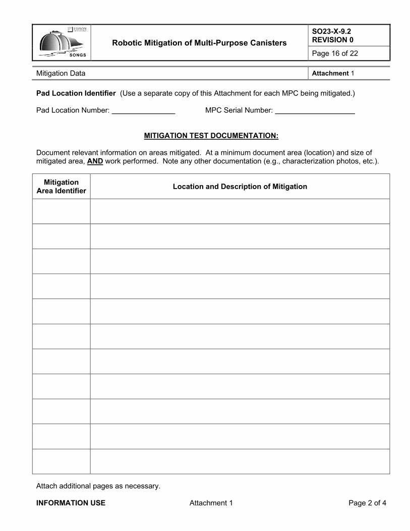
Robotic Mitigation of Multi-Purpose Canisters
SO23-X-9.2 REVISION 0
Page 16 of 22
Mitigation Data Attachment 1
Pad Location Identifier (Use a separate copy of this Attachment for each MPC being mitigated.) Pad Location Number: MPC Serial Number:
Attach additional pages as necessary. INFORMATION USE Attachment 1 Page 2 of 4
MITIGATION TEST DOCUMENTATION:
Document relevant information on areas mitigated. At a minimum document area (location) and size of mitigated area, AND work performed. Note any other documentation (e.g., characterization photos, etc.).
Mitigation Area Identifier
Location and Description of Mitigation

Robotic Mitigation of Multi-Purpose Canisters
SO23-X-9.2 REVISION 0
Page 17 of 22
Mitigation Data Attachment 1
Pad Location Identifier (Use a separate copy of this Attachment for each MPC being mitigated.) Pad Location Number: MPC Serial Number: Mitigation Area Identifier:
Attach additional pages as necessary. INFORMATION USE Attachment 1 Page 3 of 4
PRE-TEST DATA
(Testing may be completed after all work is complete.)
TEST ACCEPTANCE CRITERIA VALUE PASS / FAIL [1]
Adhesion Greater than 10,000 psi
Porosity Less than 2%
Hardness 227 to 307 HV
POST TEST DATA
TEST ACCEPTANCE CRITERIA VALUE PASS / FAIL [1]
Adhesion Greater than 10,000 psi
Porosity Less than 2%
Hardness 227 to 307 HV
[1] Document any failed Acceptance Criteria in an AR with justification, if any, of overall testing
acceptance.

Robotic Mitigation of Multi-Purpose Canisters
SO23-X-9.2 REVISION 0
Page 18 of 22
Mitigation Data Attachment 1
INFORMATION USE Attachment 1 Page 4 of 4
NORTH
NORTH
Top of MPC

Robotic Mitigation of Multi-Purpose Canisters
SO23-X-9.2 REVISION 0
Page 19 of 22
Camera Characterization System Accuracy Attachment 2
INFORMATION USE Attachment 2 Page 1 of 2
1.0 Obtain the following from the calibration certificate for the GE Borescope:
GE Borescope Model / Serial Number:
Calibration Date:
Calibration Due Date:
Accepted by / Date: /
Type of Test: ☐ AS FOUND ☐ AS LEFT
2.0 Using the GE-supplied verification block with known width and depth, MEASURE width and depth
using the GE Borescope:
Verification Block Serial Number:
Calibration Date:
Calibration Due Date:
Accepted by / Date: /
Known Value Width Depth Delta
Target A: 0.100”
Target B: 1.00 mm
Performed by / Date: /
Accepted by / Date: /
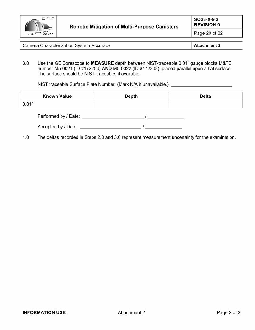
Robotic Mitigation of Multi-Purpose Canisters
SO23-X-9.2 REVISION 0
Page 20 of 22
Camera Characterization System Accuracy Attachment 2
INFORMATION USE Attachment 2 Page 2 of 2
3.0 Use the GE Borescope to MEASURE depth between NIST-traceable 0.01” gauge blocks M&TE
number M5-0021 (ID #172253) AND M5-0022 (ID #172308), placed parallel upon a flat surface. The surface should be NIST-traceable, if available:
NIST traceable Surface Plate Number: (Mark N/A if unavailable.)
Known Value Depth Delta
0.01”
Performed by / Date: /
Accepted by / Date: /
4.0 The deltas recorded in Steps 2.0 and 3.0 represent measurement uncertainty for the examination.

Robotic Mitigation of Multi-Purpose Canisters
SO23-X-9.2 REVISION 0
Page 21 of 22
Summary of Changes Attachment 3
INFORMATION USE Attachment 3 Page 1 of 2
Author: Frank Grovich
Reason Description of Change Reviewer(s) (by title or division)
50.59/ 72.48
Step, Section, Attachment
or Page
0418-29687 New procedure to perform mitigation activities on the Test Multi Purpose Canister (MPC). Already Approved by: SCN 0419-29687-7
All AA
Entire Document
Added applicable steps for performing Pre and Post Mitigation Robotic Examination of the Test Canister from SO23-X-9.1.
Already Approved by: SO23-X-9.1, Revision 2
All AA
Revision 0 50.59, and 72.48 Applicability determination. Determined 50.59 DNA and 72.48 APPLIES.
50.59/72.48 A
Cyber Security applicability determination. Determined that Cyber Security Review is NOT required.
Cyber A
Emergency Plan 50.54(q) applicability determination. Determined that EP Review is NOT required.
EP A
Physical Security Plan 50.54(p) applicability determination. Determined that Security Review is NOT required.
Security A
Fire Protection 50.48(f) applicability determination. Determined that Fire Protection Review is NOT required.
Fire Protection
A
Nuclear Oversight Review Required and Quality Class determination. NO review NOT required
NOD A

Robotic Mitigation of Multi-Purpose Canisters
SO23-X-9.2 REVISION 0
Page 22 of 22
Summary of Changes Attachment 3
INFORMATION USE Attachment 3 Page 2 of 2
Required Reviewers Name
Emergency Plan 50.54(q) K. Gallion
Physical Security Plan 50.54(p) R. Quam
Fire Protection 50.48(f) D. Arai
50.59 Frank Grovich
72.48 APPLIES Frank Grovich
Cyber Security Mike Chandler
Nuclear Oversight APPLIES Reviews at Approval (see below)
Procedure Owner or designee Randall Granaas
Other Reviewers
Operations Mike Powell
Engineering Brian Sarno
Maintenance Joe Holcomb
Decom Project John Patterson
SONGS Aging Management Allen Williams
Approvers:
Cognizant Supervisor N/A for Revision
Nuclear Oversight Final Anita Kowal
CFDM / Designee Final Jerry Stephenson