Embed Size (px)
Citation preview

State of CaliforniaAir Resources Board
Method 421
Determination of Gaseous Chloride andFluoride in Emissions from Stationary Sources
Adopted: January 22, 1987Amended: December 13, 1991

December 1991 CARB Method 421 Page i
TABLE OF CONTENTS
Page
1. APPLICABILITY AND PRINCIPLE............................................................11.1 Applicability......................................................................................11.2 Principle ...........................................................................................1
2. RANGE, SENSITIVITY, AND PRECISION ................................................12.1 Range and Sensitivity ......................................................................12.2 Precision ..........................................................................................1
3. INTERFERENCES .....................................................................................23.1 Adjacent Anion Peaks......................................................................23.2 Contamination..................................................................................23.3 Particulate Material ..........................................................................23.4 “Water Dip” Negative Peak ..............................................................23.5 Corrective Action .............................................................................2
4. APPARATUS .............................................................................................34.1 Sampling Train.................................................................................3
4.1.1 Probe Liner ...........................................................................34.1.2 Impingers ..............................................................................3
4.2 Equipment Recovery and Sample Recovery ...................................44.2.1 Brushes and Implements ......................................................44.2.2 Wash Bottles.........................................................................44.2.3 Sample Storage Containers ..................................................44.2.4 Graduated Cylinder and/or Balance......................................44.2.5 Funnel ...................................................................................4
4.3 Analysis ...........................................................................................44.3.1 Balance – Analytical..............................................................44.3.2 Sample Bottles......................................................................44.3.3 Pipettes .................................................................................54.3.4 Volumetric Flasks..................................................................54.3.5 Ion Chromatograph ...............................................................5
4.3.5.1 Anion Guard Column ............................................54.3.5.2 Anion Separator Column.......................................54.3.5.3 Anion Suppressor .................................................54.3.5.4 Pump.....................................................................54.3.5.5 Flow Gauges.........................................................54.3.5.6 Detector ................................................................6
4.3.6 Filtering System ....................................................................6
5. REAGENTS................................................................................................65.1 Sampling..........................................................................................6
5.1.1 Miscellaneous Technical Materials........................................6

December 1991 CARB Method 421 Page ii
5.1.2 Water ....................................................................................65.1.3 Impinger Solution ..................................................................6
5.2 Sample Recovery.............................................................................75.2.1 Recovery Rinse Solution.......................................................7
5.3 Analysis ...........................................................................................75.3.1 Reagent Water ......................................................................75.3.2 Eluent Solution......................................................................75.3.3 Sulfuric Acid ..........................................................................75.3.4 Anion Suppressor Regeneration Solution .............................75.3.5 Stock Chloride Standard Solution, 1000 mg/L ......................75.3.6 Intermediate Stock Chloride Standard ..................................85.3.7 Chloride Calibration Standards .............................................85.3.8 Stock Fluoride Standard Solution, 1000 mg/L.......................85.3.9 Intermediate Stock Fluoride Standard...................................85.3.10 Fluoride Calibration Standards..............................................8
6. PROCEDURE.............................................................................................86.1 Sampling..........................................................................................8
6.1.1 Pretest Preparation ...............................................................86.1.2 Preliminary Determinations ...................................................8
6.1.2.1 Sampling Time Selection ......................................96.1.3 Preparation of Collection Train..............................................96.1.4 Leak-Check Procedures........................................................96.1.5 Sampling Train Operation .....................................................96.1.6 Calculation of Percent Isokinetic .........................................10
6.2 Sample Recovery...........................................................................106.2.1 Container No. 1 (Impingers)................................................106.2.2 Field Blank ..........................................................................116.2.3 Container No. 2 (Silica Gel) ................................................11
6.3 Sample Preparation .......................................................................116.3.1 Container No. 1 (Impingers)................................................116.3.2 Field Blank ..........................................................................12
6.4 Analysis .........................................................................................126.4.1 Chromatograph Conditions .................................................12
6.4.1.1 Columns..............................................................126.4.1.2 Detector ..............................................................126.4.1.3 Eluent..................................................................126.4.1.4 Sample Loop.......................................................126.4.1.5 Pump Volume .....................................................126.4.1.6 Calibration...........................................................13
6.4.2 Chromatographic Analysis ..................................................136.4.3 Container No. 2 (Silica Gel) ................................................14
7. CALIBRATION AND QUALITY CONTROL.............................................147.1 Sampling Train Calibration.............................................................147.2 Standard Calibration Curves..........................................................14

December 1991 CARB Method 421 Page iii
7.2.1 Preliminary adjustment........................................................147.2.2 Calibration Injections and Data ...........................................147.2.3 Analytical Limit of Detection (LOD) .....................................15
7.3 Quality Control ...............................................................................157.3.1 Minimum Requirements ......................................................157.3.2 Initial Demonstration of Capability.......................................16
7.3.2.1 Preparation of Quality Control Samples..............167.3.2.2 Analysis of Quality Control Samples ...................167.3.2.3 Calculation of Percent Recovery.........................167.3.2.4 Performance Criteria ...........................................16
7.3.3 Records of Performance .....................................................177.3.3.1 Control Charts.....................................................17
7.3.4 Daily Check of Percent Recovery........................................177.3.5 Blanks, Calibration Checks and Duplicates.........................177.3.6 Additional Quality Assurance Practices...............................17
7.3.6.1 Field Duplicates ..................................................187.3.6.2 Confirmation Checks...........................................187.3.6.3 Interlaboratory Performance Checks ..................18
8. CALCULATIONS .....................................................................................188.1 Nomenclature ................................................................................188.2 Dry Gas Volume ............................................................................198.3 Volume of Water Vapor and Moisture Content ..............................198.4 Concentrations...............................................................................19
8.4.1 Total Equivalent HCl and HF in Sample..............................198.4.2 Equivalent HCl and HF Concentrations In Stack Gas .........19
8.5 Isokinetic Variation and Acceptable Results ..................................20
9. REPORTING REQUIREMENTS ..............................................................209.1 Report of Analytical Laboratory......................................................209.2 Report of Source Tester to Data User ...........................................20
10. ALTERNATIVE TEST METHODS ...........................................................21
11. BIBLIOGRAPHY ......................................................................................21
FIGURE 1: Method 421 Sampling Train...........................................................22

December 1991 CARB Method 421 Page 1
Method 421
Determination of Gaseous Chloride and FluorideIn Emissions From Stationary Sources
1. APPLICABILITY AND PRINCIPLE
1.1 Applicability
This method is applicable to the quantitative determination of gaseouschloride and fluoride in emissions from stationary sources. It detectsgaseous chloride and fluoride compounds which can be absorbed andionized in a mildly basic buffer solution, and also detects volatile chlorideand fluoride compounds in aerosol mists. Hydrochloric acid (HCl) andhydrofluoric acid (HF) are assumed to be the principle compoundsdetected when testing combustion processes.
1.2 Principle
Gas with entrained aerosols is extracted isokinetically from the stack witha heated glass or quartz probe and passed through a heated filter to aseries of chilled impingers where gaseous chlorides and fluorides areabsorbed in a solution of sodium bicarbonate and sodium carbonate. Thisimpinger solution is analyzed for chloride and fluoride by ionchromatography with conductivity detection. The chloride and fluoridepeaks are identified by characteristic retention times and quantified byreference to external standards.
2. RANGE, SENSITIVITY, AND PRECISION
2.1 Range and Sensitivity
Range and sensitivity will vary depending on analytical instrumentationand other factors including composition of the stack gas sampled.Quantitative measurement of HCl and HF concentrations from fractionalppmv levels to a few percent is achievable.
2.2 Precision
Precision expressed as sample standard deviation and accuracyexpressed as average percent recovery are determined as specified insection 7.3 and will vary depending on various factors including operatorand instrumentation capabilities and composition of the stack gassampled.
December 1991 CARB Method 421 Page 2
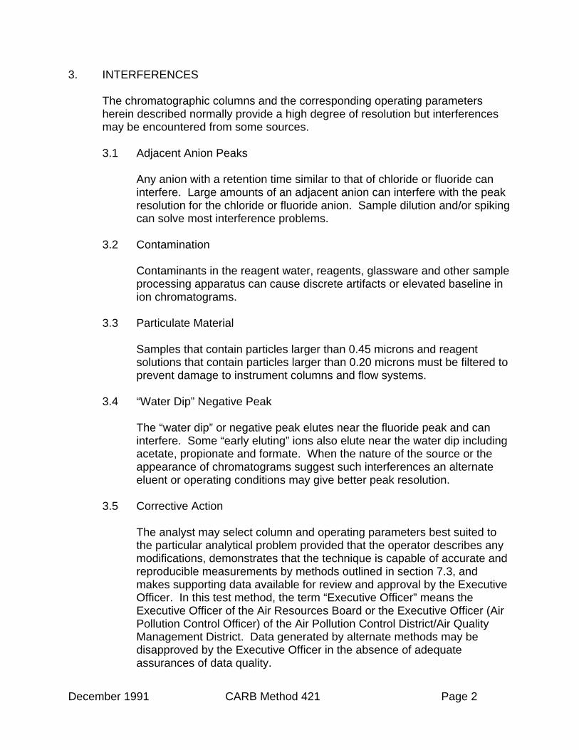
3. INTERFERENCES
The chromatographic columns and the corresponding operating parametersherein described normally provide a high degree of resolution but interferencesmay be encountered from some sources.
3.1 Adjacent Anion Peaks
Any anion with a retention time similar to that of chloride or fluoride caninterfere. Large amounts of an adjacent anion can interfere with the peakresolution for the chloride or fluoride anion. Sample dilution and/or spikingcan solve most interference problems.
3.2 Contamination
Contaminants in the reagent water, reagents, glassware and other sampleprocessing apparatus can cause discrete artifacts or elevated baseline inion chromatograms.
3.3 Particulate Material
Samples that contain particles larger than 0.45 microns and reagentsolutions that contain particles larger than 0.20 microns must be filtered toprevent damage to instrument columns and flow systems.
3.4 “Water Dip” Negative Peak
The “water dip” or negative peak elutes near the fluoride peak and caninterfere. Some “early eluting” ions also elute near the water dip includingacetate, propionate and formate. When the nature of the source or theappearance of chromatograms suggest such interferences an alternateeluent or operating conditions may give better peak resolution.
3.5 Corrective Action
The analyst may select column and operating parameters best suited tothe particular analytical problem provided that the operator describes anymodifications, demonstrates that the technique is capable of accurate andreproducible measurements by methods outlined in section 7.3, andmakes supporting data available for review and approval by the ExecutiveOfficer. In this test method, the term “Executive Officer” means theExecutive Officer of the Air Resources Board or the Executive Officer (AirPollution Control Officer) of the Air Pollution Control District/Air QualityManagement District. Data generated by alternate methods may bedisapproved by the Executive Officer in the absence of adequateassurances of data quality.

December 1991 CARB Method 421 Page 3
4. APPARATUS
Mention of trade names or specific products does not constitute endorsement bythe California Air Resources Board.
4.1 Sampling Train
The following sampling apparatus is required. The tester may use analternative sampling apparatus only after the Executive Officer determinesthat it is equivalent to the required sampling apparatus for the purposes ofthis test method.
A schematic diagram of the sampling train is shown in Figure 1. Theequipment required for this train is the same as described in Method 5except as follows:
NOTE: Except where otherwise indicated, references to othersupporting test methods such as “Method 5” or “Method 2” areto those test methods adopted by the California Air ResourcesBoard.
4.1.1 Probe Liner
Same as described in Method 5 except use only quartz orborosilicate glass liners.
4.1.2 Impingers
Four impingers are connected in series with leak-free glass balljoint fittings or similar leak-free, non-contaminating, inert fittingssuch as Teflon. The first, third, and fourth impingers are of theGreenburg-Smith design modified by replacing the tip with a 1-cm(0.5 in.) I.D. glass tube extending to 1 cm from the bottom of theflask. The second impinger is of the Greenburg-Smith design withthe standard tip. A silica gel cartridge may be substituted for thefourth impinger.
As described in section 6.1.3 the first and second impingers willeach contain 100 ml of impinger solution (see section 5.1.3). Thethird will be empty, and the fourth will contain a known weight ofsilica gel or equivalent dessicant.
A thermometer which measures temperatures to within 1°C (2°F),should be placed at the outlet of the fourth impinger.

December 1991 CARB Method 421 Page 4
4.2 Sample Recovery
The following items are needed:
4.2.1 Brushes and Implements
Probe liner and nozzle brushes, petri dishes, plastic storagecontainers, funnel and rubber policeman as in Method 5. Used onlyin equipment cleanup, not in sample recovery.
4.2.2 Wash Bottles
Used only in equipment cleanup, not in sample recovery.
4.2.3 Sample Storage Containers
Chemically resistant, borosilcate glass bottles for impinger solutionsand washes, 1000 mL. Teflon or high-density polyethylene orpolypropylene bottles may be used. Use screw-cap liners that areeither rubber-backed Teflon or leak-free, impermeable and resistantto chemical attack. (Narrow mouth bottles are less prone toleakage).
4.2.4 Graduated Cylinder and/or Balance
To measure condensed water to within 2 mL or 1 g. Graduatedcylinder, if used, should be glass, 500 ml (or larger), withsubdivisions no greater than 5 mL.
4.2.5 Funnel
To aid in sample recovery. Only a glass funnel may be used.
4.3 Analysis
The following equipment is needed:
4.3.1 Balance –Analytical
Capable of accurately weighing to the nearest 0.0001 g.
4.3.2 Sample bottles
Glass, Teflon, or high-density polyethylene or polypropylene. Thecapacity should be sufficient to allow replicate analyses of the anionof interest.

December 1991 CARB Method 421 Page 5
4.3.3 Pipettes
An assortment of sizes.
4.3.4 Volumetric Flasks
100-mL, 250-mL and 1000-mL.
4.3.5 Ion Chromatograph
Analytical system complete with ion chromatograph and all requiredaccessories including syringes, analytical columns, compressed air,detector, and strip chart recorder and/or data system. A datasystem is recommended for peak integration. The ionchromatograph should have at least the components listed below.The analyst may use alternative components provided that there isadequate resolution of peaks and there is no impairment ofprecision and accuracy as demonstrated by the methods outlined insection 7.3.
4.3.5.1 Anion guard column
An appropriate anion guard column shall be selected(e.g., Dionex model AG4A or equivalent).
4.3.5.2 Anion separator column
An appropriate anion separator column shall be selected(e.g., Dionex model AS4A or equivalent).
4.3.5.3 Anion Suppressor
An appropriate anion suppressor shall be selected (e.g.,Dionex Anion Micromembrane Suppressor or equivalent).
4.3.5.4 Pump
Capable of maintaining a steady flow as required by thesystem.
4.3.5.5 Flow gauges
A gauge may be necessary for measuring the specifiedsystem flow rate; metering pump systems may be used inplace of gauges.

December 1991 CARB Method 421 Page 6
4.3.5.6 Detector
Conductivity cell. Approximately 6 uL volume, (e.g.,Dionex, or equivalent).
4.3.6 Filtering System
0.45 micron Millipore filter and Millipore vacuum filtration unit orequivalent.
5. REAGENTS
Unless otherwise specified, use American Chemical Society reagent grade (orequivalent) chemicals throughout.
Mention of trade names or specific products does not constitute endorsement bythe California Air Resources Board.
5.1 Sampling
The following reagents are needed:
5.1.1 Miscellaneous Technical Materials
Filters, silica gel, and crushed ice as specified in Method 5.
5.1.2 Water
Deionized, distilled water which conforms to ASTM SpecificationD1193-77, Type 3. If high concentrations of organic matter are notexpected to be present, the analyst may omit the potassiumpermanganate test for oxidizable organic matter.
5.1.3 Impinger Solution
A solution of 1.7 mM sodium bicarbonate and 1.8 mM sodiumcarbonate. Dissolve 0.5712 g sodium bicarbonate (NaHCO3) and0.7631 g of sodium carbonate (Na2CO3) in reagent water (5.1.2),and dilute to 4 liters. A portion of the impinger solution used for thetest must be reserved for use as a reagent blank.
Note: Bacteria can grow in the carbonate/bicarbonate solutions describedabove and it is good practice to make up fresh stocks frequentlyand filter before use to protect the chromatographic column.

December 1991 CARB Method 421 Page 7
5.2 Sample Recovery
5.2.1 Recovery Rinse Solution
Same as impinger solution (5.1.3).
5.3 Analysis
The following reagents are needed:
5.3.1 Reagent water
Same as 5.1.2 above. Verify that the conductance is 1 micro-Mhoor less.
5.3.2 Eluent solution
A solution of 1.7 mM sodium bicarbonate and 1.8 mM sodiumcarbonate (see Section 5.1.3) or other eluent recommended by themanufacturer for use with the ion chromatograph equipmentdescribed in Section 6.4.
5.3.3 Sulfuric Acid
Concentrated.
5.3.4 Anion Suppressor Regeneration Solution
Follow ion chromatograph manufacturer’s recommendations.Sulfuric acid, 0.025 N, is recommended for use with the Dionexequipment described in section 4.3.5.3. Dilute 2.8 mL concentratedsulfuric acid (H2SO4) to 4 liters with reagent water.
5.3.5 Stock Chloride Standard Solution, 1000 mg/L
This may be purchased as a certified solution or prepared formACS reagent grade materials (dried at 105°C for 30 min.) asfollows: Dissolve 1.6485 g sodium chloride (NaCl) in reagent water(5.1.2) and dilute to 1 liter. Stock standards are stable for at leastone month when stored at 4°C.
NOTE:Chloride and fluoride standards may be combined in solutionscontaining both ions if desired. Section 5.3.8 describes theprocedure for the preparation of fluoride standards.

December 1991 CARB Method 421 Page 8
5.3.6 Intermediate Stock Chloride Standard
Pipet 200 mL of the stock standard (5.3.5) into a 1000-mLvolumetric flask, and dilute to volume with eluent solution (5.1.3).
5.3.7 Chloride Calibration Standards
Add accurately measured volumes of the intermediate standard(5.3.6) to a volumetric flask and dilute to volume with eluentsolution (5.1.3). Prepare standards at at least three concentrationlevels (see section 7.2).
5.3.8 Stock Fluoride Standard Solution, 1000 mg/L
This may be purchased as a certified solution or prepared fromACS reagent grade materials (dried at 105°C for 30 min.) asfollows: Dissolve 2.210 g sodium fluoride (NaF) in reagent water(5.1.2) and dilute to 1 liter. Stock standards are stable for at leastone month when stored at 4°C.
5.3.9 Intermediate Stock Fluoride Standard
Pipet 200 mL of the stock fluoride standard (5.3.8) into a 1000-mLvolumetric flask , and dilute to volume with eluent solution (5.1.3).
5.3.10 Fluoride Calibration Standards
Add accurately measured volumes of the intermediate fluoridestandard (5.3.9) to a volumetric flask and dilute to volume witheluent solution (5.1.3). Prepare standards of at least threeconcentration levels (see section 7.2).
6. PROCEDURE
6.1 Sampling
Because of the complexity of this method, testers should be trained andexperienced with the test procedures in order to ensure reliable results.
6.1.1 Pretest Preparation
Follow the same general procedure described in Method 5, exceptthe filter need not be weighed.
6.1.2 Preliminary Determinations

December 1991 CARB Method 421 Page 9
Follow the same general procedure described in Method 5.
6.1.2.1 Sampling Time Selection
Considering the nature of the source, select a samplingtime period estimated to yield quantifiable concentrationsin the impinger solution without overloading the filter withparticulate matter or the impingers with condensedmoisture.
6.1.2.2 Sampling Run Requirements
Requirements specifying the minimum number ofsampling runs, total volume of gas sampled, and totalsampling time may be imposed by regulation or by theauthority requiring testing. In the absence of suchrequirements, the test program should be planned so thatthe test results are representative of emissions duringnormal operating conditions. At a minimum, threesampling runs must be performed in sequence for aminimum sampling time of 1 hour each.
6.1.3 Preparation of Collection Train
Follow the same general procedure given in Method 5 exceptsubstitute impinger solution (5.1.3) for deionized water. Assemblethe train as shown in Figure 1.
NOTE:One sampling train must be used as a field blank (6.2.2). Chargethe impingers with impinger solution, assemble the train andperform the leak check but do not draw sample gas through thetrain. Recover the field blank according to section 6.2.
6.1.4 Leak-Check Procedures
Follow the general leak-check procedures given in Method 5(Pretest Leak Check, Leak Checks During the Sample Run, andPost-Test Leak Check).
6.1.5 Sampling Train Operation
Follow the same general procedure given in Method 5. For eachrun, record the data required on a data sheet such as the “FieldData Record” form shown in Method 5.

December 1991 CARB Method 421 Page 10
6.1.6 Calculation of Percent Isokinetic
Calculate as in Method 5.
6.2 Sample RecoveryAllow the probe to cool. Inspect the train prior to and during disassemblyand note any abnormal conditions. Disconnect the impingers, and treatthem in the following manner:
6.2.1 Container No. 1 (Impingers)
If the volume of liquid is large, the tester may place the impingersolutions in several containers. Dismantle each of the first threeimpingers and connecting glassware in the following manner:
1. Disconnect and cap the ball joints.
2. Rotate and agitate each impinger to remove condensatefrom impinger walls.
3. Transfer the contents of the impingers to a 500-mLgraduated cylinder. Remove each outlet ball joint’s cap anddrain the contents through this opening. Do not separate theimpinger parts (inner and outer tubes) while transferring theircontents to the cylinder. Measure the liquid volume to within+2 mL. Alternatively, determine the weight of the liquid towithin +0.5 g. Record in the log the volume or weight of theliquid present, and the occurrence of any color or film in theimpinger catch. The liquid volume or weight is needed,along with the silica gel data, to calculate the stack gasmoisture content (see Method 5).
4. Transfer the contents, once measured, to Container No. 1.
NOTE:In steps 5 and 6 below, measure and record the totalamount of recovery rinse solution used for rinsing.
5. Pour a measured amount, approximately 30 mL, of recoveryrinse solution (5.2.1) into each of the first three impingersand agitate the impingers. Drain the recovery rinse solutionthrough the outlet arm of each impinger into Container No. 1.Repeat this operation a second time; inspect the impingersfor any abnormal conditions.

December 1991 CARB Method 421 Page 11
6. Rinse each piece of glassware connecting the impingerstwice with a measured amount of recovery rinse solution,adding this rinse into Container No. 1.
Mark the height of the fluid level to determine whetherleakage occurs during transport. Label the container toclearly identify its contents.
NOTE:Do NOT add any particulate material or cleanup rinse fromthe probe, filter or filter holder to Container No. 1; rather,DISCARD any such material if not required for otheranalysis.
6.2.2 Field Blank
At least one field blank must be collected. The field blank must betreated the same as the samples except that no sample gas isdrawn through the sampling train. The blank must be analyzed asa contamination check for the solutions and apparatus used in thefield.
6.2.3 Container No. 2 (Silica Gel)
Check the color of the indicating silica gel to determine if it hasbeen completely spent, and note its condition. Transfer the silicagel from the fourth impinger to the original container and seal. Thetester may use a funnel to pour the silica gel, and rubber policemanto remove the silica gel from the impinger. It is not necessary toremove the small amount of particles that may adhere to theimpinger walls and are difficult to remove. Since the gain in weightis to be used for moisture calculations, do not use water or anyother liquids to transfer the silica gel. If a balance is available in thefield, the tester may follow the procedure for weighing ContainerNo. 2 under section 6.4.3.
6.3 Sample Preparation
6.3.1 Container No. 1 (Impingers)
Check the liquid level to determine whether any sample was lostduring shipment. If a noticeable amount of leakage has occurred,either void the sample or determine the volume lost from thedifference between the initial and final solution levels, and use thisvalue to adjust the final results. Adjustments must be reported withtest results and adjusted results are subject to approval by theExecutive Officer.

December 1991 CARB Method 421 Page 12
Filter the sample through a Millipore membrane filter (4.3.6) into avolumetric flask, and dilute to volume with deionized distilled water.
6.3.2 Field Blank
Filter through a Millipore membrane filter (4.3.6) into a volumetricflask. Dilute to the same volume as the sample (see section 6.3.1).
6.4 AnalysisThe analysis should be done only by or under the supervision of analystsexperienced in the use of ion chromatography and in the interpretation ofthe resulting chromatograms. Each analyst should demonstrate the abilityto generate acceptable results with this method using the proceduredescribed in section 7.3.2.
6.4.1 Chromatograph Conditions
The following operating conditions are recommended for the ionchromatograph. Other columns, chromatograph conditions, ordetectors may be used if the conditions of section 7.3.2 are met.
6.4.1.1 Columns
As specified in 4.3.5.
6.4.1.2 Detector
As specified in 4.3.5. Select the sensitivity required forthe analysis based on estimated sample concentration.Follow the manufacturer’s instructions for obtaining theoptimum temperature compensating factor for eachcolumn set and eluent batch. This is especially importantwhen operating at high sensitivities.
6.4.1.3 Eluent
As specified in 5.3.2.
6.4.1.4 Sample Loop
100 uL.
6.4.1.5 Pump Volume
2.30 mL/min.

December 1991 CARB Method 421 Page 13
6.4.1.6 Calibration
Calibrate the ion chromatograph, and prepare acalibration curve as described in section 7.2.
6.4.2 Chromatographic Analysis
Load and inject a fixed amount of well mixed sample (at least 10loop volumes). The first samples to be analyzed should be areagent blank (5.1.3) and calibration standards followed by a qualitycontrol sample. Use the same size loop for standards andsamples. Flush the injection loop thoroughly with each newsample. An automated constant volume injection system may alsobe used.
For each sample, record the injection time, injection volume, flowrate, detector sensitivity setting, recorder chart speed, peak heightor area, and retention time.
It is recommended that all injections of field samples be duplicated.At least 10% of field sample injections must be duplicated (seesection 7.3.5 below).
If a peak response exceeds the working range of the system, dilutethe sample with an appropriate amount of reagent water and re-analyze. Calculate a dilution factor (<1) for use in the finalcalculations.
Run a reagent blank (5.1.3) and a standard after every 10 samplesto check the chromatograph calibration. Recalibrate as necessary.
The width of the retention time window used to make identificationsshould be based upon measurements of actual retention timevariations of standards over the course of a day. Three times thestandard deviation of a retention time can be used to calculate asuggested window size for an anion. However, the experience ofthe analyst should weigh heavily in the interpretation ofchromatograms.
If any chromatogram fails to produce adequate resolution, or ifidentification of an anion is questionable, spike the sample with anappropriate amount of standard, and reanalyze.

December 1991 CARB Method 421 Page 14
6.4.3 Container No. 2 (Silica Gel)
The tester may conduct this step in the field. Weigh the spent silicagel (or silica gel plus impinger) to the nearest 0.5 g; record thisweight.
7. CALIBRATION AND QUALITY CONTROL
7.1 Sampling Train Calibration
Calibrate the sampling train components according to the requirements ofMethod 5.
7.2 Standard Calibration Curves
Establish the ion chromatographic operating parameters indicated insection 6.4.1 above. Prepare a sufficient number of fluoride and chloridestandards (sections 5.3.7 and 5.3.10), or combined chloride and fluoridestandards, to construct an accurate calibration curve for each ion. Thisshould include a minimum of four concentrations each for chloride andfluoride and a reagent blank (5.1.3). The concentration of the loweststandard should be near, but above the method detection limit or the lowend of the concentration range for the attenuator setting. The otherstandards should correspond to the range of concentrations expected inthe sample. Additional standards may be needed to define any non-linearregions.
7.2.1 Preliminary Adjustment
Pump eluent through the column. After the system is equilibratedand the detector baseline is stable adjust zero to approximately 10percent of chart. Inject the highest calibration standard. As thehighest calibration standard elutes, adjust the largest peak toapproximately 90 percent of chart.
7.2.2 Calibration Injections and Data
Inject 0.01 to 1.0 mL (determined by injection loop volume) of eachcalibration standard starting with the highest concentration.
For each peak record the anion (chloride or fluoride), concentrationof the standard, peak height or area, the injection time (the positionof the pen on the chart at the time of sample injection), injectionvolume, flow rate, attenuator setting, and recorder chart speed.Measure the distance on the chart from the injection time to the

December 1991 CARB Method 421 Page 15
time at which the peak maximum occurs. This distance divided bythe chart speed is defined as the anion retention time.
It is recommended that injections of standards be duplicated. Plotthe peak height or area of each standard (y-axis) versus thecorresponding calibration standard’s concentration (x-axis).
7.2.3 Analytical Limit of Detection (LOD)
The analytical limit of detection (LOD) should be calculated at leastonce every six months, or whenever there is a change in operatoror instrumentation. No data shall be reported below the LOD.
Calculate the LOD by the following equation:
LOD = A + 3S
Where:
A is the least squares intercept from the multipoint calibrationcurve.
S is the standard deviation of replicate determinations of the lowestconcentration standard. At least 7 replicates are required. Thelowest concentration standard must be approximately 1 to 5 timesthe estimated LOD.
7.3 Quality Control
7.3.1 Minimum Requirements
The minimum quality control requirements are an initialdemonstration of analytical performance (as described in section7.3.2), daily analysis of quality control samples for determination ofpercent recovery, and analysis of duplicates, calibration standardsand blanks after every ten field samples as a continuing check onperformance. The laboratory should maintain performance recordsto provide assurance of the quality of data that are generated.
Whenever changes in method as permitted herein are made orwhen there is a change in operator, instrumentation or reagents,performance should be rechecked by the procedure described insection 7.3.2 below.

December 1991 CARB Method 421 Page 16
7.3.2 Initial Demonstration of Capability
Before performing any analyses, the analyst should demonstratethe ability to generate acceptable accuracy and precision with thismethod using quality control samples.
7.3.2.1 Preparation of Quality Control Samples
Select a representative spike concentration of 2 mg/L ormore for each anion. Use the stock standard to preparea quality control sample with concentration in eluentsolution that is 100 times greater than the valuesselected above. Use a pipet to add 1.00 mL of thissolution to each of four 100-mL volumetric flasks. Fill theflasks with eluent solution to produce four 100 mLaliquots. Samples used for percent recovery checksmust not be used to construct or correct the calibrationcurve.
7.3.2.2 Analysis of Quality Control Samples
Analyze the aliquots according to the procedure insection 6.4.2.
7.3.2.3 Calculation of Percent Recovery
Calculate percent recovery for each anion in each aliquotas 100 % x (result)/(expected result). Calculate theaverage percent recovery (R), and the sample standarddeviation (s) of the percent recovery, for each anion.
7.3.2.4 Performance Criteria
An average percent recovery between 95.0% and 105%and a sample standard deviation for percent recovery notgreater than 15% should be feasible for a competentanalyst with appropriate equipment and materials whenanalyzing concentrations of 2 mg/L or greater in samplesprepared as above. If performance is outside theselimits, review potential problem areas and repeat theperformance test. More restrictive performance criteriamay be appropriate when dictated by special testingobjectives or when the limits above are outside statisticalcontrol limits (usually set at + 3 standard deviations)based on a laboratory’s past performance.

December 1991 CARB Method 421 Page 17
7.3.3 Records of Performance
Results of quality control checks including percent recovery checksand injection of quality control samples as specified in section 7.3.5below should be kept in an ongoing file maintained and availablefor continuing reference.
7.3.3.1 Control Charts
Control charts may optionally be used to follow trends inperformance for quality control samples in a particularconcentration range. For concentrations of 2.0 mg/L orabove, control limits should be at least as restrictive asthe limits set out in section 7.3.2.4.
7.3.4 Daily Check of Percent Recovery
Each day samples are analyzed, and after every 40 field samples(including field blanks) have been analyzed, and after any changein reagents or instrumentation, the percent recovery “R” shall firstbe determined for each anion by analyzing in duplicate a spikedsample prepared as described in 7.3.2.1 prior to analysis ofsamples from the field.
7.3.5 Blanks, Calibration Checks and Duplicates
After every 10 field sample (including field blank) injections and atthe end of the day, quality control samples shall be analyzedincluding a reagent blank, a calibration standard and (if all fieldsamples are not duplicated as recommended) a duplicate of atleast one of the preceeding field samples. If duplicates orcalibration standards deviate more than 5% from expected value orif reagent blanks produce a response greater than 10% of theaverage field sample concentration, the analyst must attempt toidentify and correct analytical problems and reanalyze the fieldsamples.
7.3.6 Additional Quality Assurance Practices
The laboratory may adopt additional quality assurance practices foruse with this method including those suggested below.
December 1991 CARB Method 421 Page 18
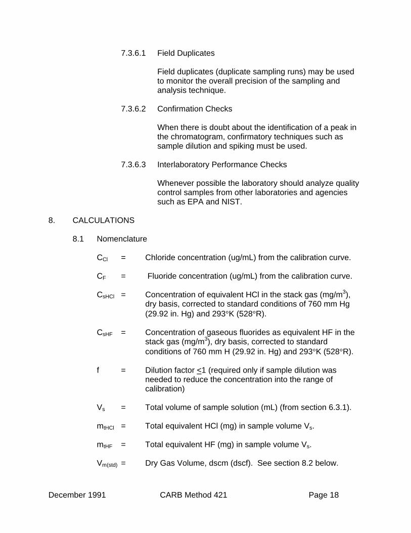
7.3.6.1 Field Duplicates
Field duplicates (duplicate sampling runs) may be usedto monitor the overall precision of the sampling andanalysis technique.
7.3.6.2 Confirmation Checks
When there is doubt about the identification of a peak inthe chromatogram, confirmatory techniques such assample dilution and spiking must be used.
7.3.6.3 Interlaboratory Performance Checks
Whenever possible the laboratory should analyze qualitycontrol samples from other laboratories and agenciessuch as EPA and NIST.
8. CALCULATIONS
8.1 Nomenclature
CCl = Chloride concentration (ug/mL) from the calibration curve.
CF = Fluoride concentration (ug/mL) from the calibration curve.
CsHCl = Concentration of equivalent HCl in the stack gas (mg/m3),dry basis, corrected to standard conditions of 760 mm Hg(29.92 in. Hg) and 293°K (528°R).
CsHF = Concentration of gaseous fluorides as equivalent HF in thestack gas (mg/m3), dry basis, corrected to standardconditions of 760 mm H (29.92 in. Hg) and 293°K (528°R).
f = Dilution factor <1 (required only if sample dilution wasneeded to reduce the concentration into the range ofcalibration)
Vs = Total volume of sample solution (mL) (from section 6.3.1).
mtHCl = Total equivalent HCl (mg) in sample volume Vs.
mtHF = Total equivalent HF (mg) in sample volume Vs.
Vm(std) = Dry Gas Volume, dscm (dscf). See section 8.2 below.

December 1991 CARB Method 421 Page 19
8.2 Dry Gas Volume
Using the data from this test, calculate Vm(std), the total volume of dry gasmetered corrected to standard conditions (20°C and 760 mm Hg), byusing the appropriate equation specified in Method 5. If necessary, adjustVm(std) for leakages as outlined in Method 5. See the field data sheet forthe average dry gas meter temperature and average orifice pressure drop.
8.3 Volume of Water Vapor and Moisture Content
Using data obtained in this test and appropriate equations in Method 5,calculate the volume of water vapor Vw(std) and the moisture content Bws ofthe stack gas.
8.4 Concentrations
8.4.1 Total Equivalent HCl and HF in Sample
Use the following equations to calculate the mass of equivalent HCland HF in the sample volume Vs:
mtHCl = CCl x 10-3 x Vs x 1.028 / f Eq. 1aandmtHF = CF x 10-3 x Vs x 1.053 / f Eq. 1b
Where:
1.028 = the conversion from chloride anion to equivalent HCl
1.053 = the conversion from fluoride anion to equivalent HF
8.4.2 Equivalent HCl and HF Concentrations in Stack Gas
Use the following equations to calculate HCl and HF concentrationsin the stack gas:
CsHCl = K x mtHCl / Vm(std) Eq. 2aandCsHCl = K x mtHCl / Vm(std) Eq. 2a
Where:
K = 35.31 ft3/m3 if Vm(std) is expressed in cubic feet
K = 1.00 m3/m3 if Vm(std) is expressed in cubic meters

December 1991 CARB Method 421 Page 20
8.5 Isokinetic Variation and Acceptable Results.
Same as in Method 5. To calculate the average stack gas velocity, usethe appropriate equation in Method 2 and the data from this field test.
9. REPORTING REQUIREMENTS
9.1 Report of Analytical Laboratory
The report of the laboratory performing analysis of field samples shouldinclude at least the following (nomenclature and units as defined in section8):
Vs for each field sample and field blank;
CCl and CF for each field sample and field blank including results ofduplicate injections;
f for each field sample and field blank;
Results for all associated quality control samples required by sections7.3.4 and 7.3.5, indicating for each the type of sample, the concentrationfound and the concentration expected;
Nature and results of any corrective action related to quality controlsamples.
9.2 Report of Source Tester to Data User
The report submitted or published by the source tester should include atleast the following (nomenclature and units as defined in section 8):
All data required above in the report of the analytical laboratory;
mtHCl and mtHF for each field sample and field blank;
Volume of water vapor and moisture content for each field sample;
Percent Isokinetic for each field sample;
Vm(std) for each field sample;
CsHCl and CsHF for each field sample.

December 1991 CARB Method 421 Page 21
10. ALTERNATIVE TEST METHODS
Alternative test methods may be used provided that they are equivalent toMethod 421 and approved in writing by the Executive Officer of the AirResources Board. The ARB Executive Officer may require the submittal of testdata or other information to demonstrate equivalency.
11. BIBLIOGRAPHY
American Society for Testing and Materials. Annual Book of ASTM Standards.Part 31; Water, Atmospheric Analysis. Philadelphia, Pa. 1974. pp. 40-42.
O’Dell, J.W., Pfaff, J.D., Gales, M.E., and McKee, G.D. “Test Method: Thedetermination of Inorganic Anions in Water by Ion Chromatography – Method300.0. U.S. Environmental Protection Agency/Environmental Monitoring andSupport Laboratory, Cincinnati, Ohio. Jan., 1984.
U.S. Environmental Protection Agency/Office of Solid Waste, Washington, D.C.,Method 9250. In “Test Methods for Evaluating Solid Waste-Physical/ChemicalMethods” SW-846 (1982).
NIOSH Manual of Analytical Methods, 3rd ed., Method 7903, Acids, Inorganic.U.S. Department of Health and Human Services DHHS (NIOSH) Publ. No. 84-100. Feb, 1984.
Cheney, J.L., and Fortune, C.R., 1979. Evaluation of a method for measuringhydrochloric acid in combustion source emissions. The Science of the TotalEnvironment. 13: 9-16.
Stationary Source Test Methods – Volume 1 – Methods for DeterminingCompliance with District Nonvehicular (Stationary Source) Emission Standards.State of California, Air Resources Board, Monitoring and Laboratory Division.

December 1991 CARB Method 421 Page 22