Embed Size (px)
Citation preview

GX1255S
QUEST GX1255S25 Watt VHF/FM
Marine Transceiver
Owner's Manual
l RTCM SC-101 DSC Distress call with your exact posi-tion when connected to a GPS
l Compact and Simple Operationl 3 year waterproof warrantyl Backlit Keypad and LCD displays latitude/longitude
when connected to a GPSl Channel Name, GPS Time or GPS Position Repeating
shown on the displayl NOAA Weather Alertl One-button access to Channel 16 and 9l Access to all US, Canadian and International Channelsl Versatile User-programmable Scan, Priority Scan and
Dual Watchl Microphone with Channel Slection.

GX1255S
TABLE OF CONTENTSSAFETY/WARNING INFORMATION ........................................................... 2FCC RADIO LICENSE INFORMATION ....................................................... 3
STATION LICENSE .................................................................................................................................. 3RADIO CALL SIGN ................................................................................................................................. 3CANADIAN SHIP STATION LICENSING ............................................................................................. 3
FCC NOTICE ................................................................................................. 41 GENERAL INFORMATION ..................................................................... 5
1.1 INTRODUCTION ............................................................................................................................... 51.2 FCC/INDUSTRY CANADA INFORMATION .................................................................................. 5
2 ACCESSORIES ....................................................................................... 62.1 PACKING LIST ................................................................................................................................. 62.2 OPTIONS ........................................................................................................................................... 6
3 INSTALLATION ....................................................................................... 73.1 LOCATION ......................................................................................................................................... 73.2 ELECTRICAL CONNECTIONS ....................................................................................................... 73.3 ACCESSORY CABLE ...................................................................................................................... 83.4 OPTIONAL CMB16 FLUSH MOUNT INSTALLATION ................................................................. 9
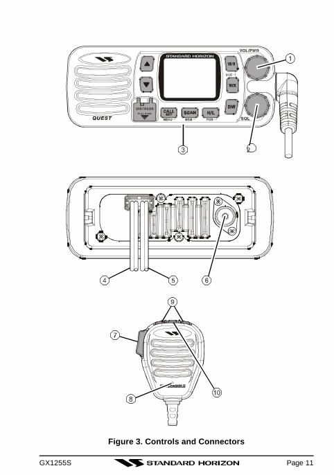
4 CONTROLS AND INDICATORS .......................................................... 104.1 CONTROLS AND CONNECTIONS ............................................................................................. 10
5 BASIC OPERATION.............................................................................. 155.1 RECEPTION ................................................................................................................................... 155.2 TRANSMISSION ............................................................................................................................. 155.3 TRANSMIT TIME-OUT TIMER (TOT) ......................................................................................... 155.4 SIMPLEX/DUPLEX CHANNEL USE ........................................................................................... 165.5 USA, CANADA, AND INTERNATIONAL MODE ......................................................................... 165.6 NOAA WEATHER CHANNELS ................................................................................................... 165.7 NOAA WEATHER ALERT ............................................................................................................ 175.8 MEMORY SCANNING (M-SCAN) ................................................................................................ 185.9 PRIORITY SCANNING (P-SCAN) ................................................................................................ 185.10 POSITION INDICATION ............................................................................................................. 195.11 TIME INDICATION ....................................................................................................................... 195.12 RESETTING THE TRANSCEIVER’S MICROPROCESSOR ................................................. 19
6 DIGITAL SELECTIVE CALLING .......................................................... 206.1 GENERAL ....................................................................................................................................... 206.1.1 Digital Selective Calling (DSC) ................................................................................................. 206.1.2 Maritime Mobile Service Identity (MMSI) ................................................................................ 206.2 SENDING A DISTRESS CALL ................................................................................................... 216.3 SENDING AN INDIVIDUAL CALL .............................................................................................. 226.4 SENDING AN ALL SHIPS CALL ............................................................................................... 236.5 RECEIVING DSC CALLS ............................................................................................................ 246.5.1 Receiving a distress call .......................................................................................................... 246.5.2 Receiving a distress relay call ................................................................................................ 246.5.3 Receiving an all ships call ....................................................................................................... 256.5.4 Receiving a geographical area call ........................................................................................ 256.5.5 Receiving an individual call ...................................................................................................... 266.5.6 Receiving a position request ................................................................................................... 27

GX1255S Page 1
7 DSC / RADIO SETUP MODE ............................................................... 287.1 LAMP ADJUSTING ........................................................................................................................ 287.2 LCD CONTRAST ADJUSTING .................................................................................................... 287.3 KEY BEEP (ON OR OFF) ............................................................................................................. 297.4 WEATHER ALERT (ON OR OFF) ................................................................................................ 297.5 CHANNEL NAME CHANGE ........................................................................................................ 307.6 TIME OFFSET ............................................................................................................................... 317.7 INDIVIDUAL DIRECTORY SETUP (DSC) ................................................................................. 327.8 INDIVIDUAL REPLY ...................................................................................................................... 337.9 INDIVIDUAL ACK .......................................................................................................................... 337.10 INDIVIDUAL RING ...................................................................................................................... 347.11 POSITION REQUEST REPLY ................................................................................................... 347.12 DSC SCANNING ......................................................................................................................... 357.13 USER MMSI INPUT .................................................................................................................... 36
8 OPERATING PRACTICES.................................................................... 378.1 EMERGENCY (CHANNEL 16 USE) ............................................................................................. 378.2 CALLING ANOTHER VESSEL (CHANNEL 16 OR 9) ................................................................ 378.3 MAKING TELEPHONE CALLS ................................................................................................... 388.4 OPERATING ON CHANNELS 13 AND 67 .............................................................................. 398.5 PROHIBITED COMMUNICATIONS ............................................................................................. 398.6 NOAA WEATHER ALERT TESTING .......................................................................................... 398.7 DIGITAL SELECTIVE CALLING (DSC) ...................................................................................... 408.7.1 USCG DSC Watch .................................................................................................................... 408.8 MARITIME MOBILE SERVICE IDENTITY (MMSI) ................................................................... 408.8.1 What is a MMSI? ...................................................................................................................... 408.9 USING DIGITAL SELECTIVE CALLING FEATURES .............................................................. 408.9.1 Distress Call ................................................................................................................................ 408.9.2 Individual Call ............................................................................................................................. 408.9.3 Urgency Call ............................................................................................................................... 408.9.4 Safety Call ................................................................................................................................... 418.10 ADDITIONAL DIGITAL SELECTIVE CALLING INFORMATION ........................................... 418.11 ABOUT VHF RADIO ................................................................................................................... 418.12 SELECTING AN ANTENNA ........................................................................................................ 418.13 COAXIAL CABLE ........................................................................................................................ 42
9 MAINTENANCE ..................................................................................... 439.1 REPLACEMENT PARTS ............................................................................................................... 439.2 FACTORY SERVICE ..................................................................................................................... 449.3 TROUBLESHOOTING CHART .................................................................................................... 459.4 CONNECTION OF GPS WITH NMEA OUTPUT ..................................................................... 46
10 CHANNEL ASSIGNMENTS .................................................................. 4711 WARRANTY........................................................................................... 5112 SPECIFICATIONS ................................................................................. 55
TABLE OF CONTENTS

GX1255SPage 2
Safety/Warning InformationThis radio is restricted to occupational use, work related operations onlywhere the radio operator must have the knowledge to control the exposureconditions of its passengers and bystanders by maintaining the minimumseparation distance of 0.6 m (2 feet).
Failure to observe these restrictions will result in exceeding the FCC RFexposure limits.
Antenna Installation:The antenna must be located at least 0.6 m (2 feet) away from passengersin order to comply with the FCC RF exposure requirements.
For roof top installation, the antenna must be placed in the center of theroof.
ON-LINE WARRANTY REGISTRATION
Please visit www.standardhorizon.com to register the QUEST MarineVHF. It should be noted that visiting the Web site from time to time maybe beneficial to you, as new products are released they will appear onthe STANDARD HORIZON Web site.PRODUCT SUPPORT INQUIRIESIf you have any questions or comments regarding the use of the QUEST,you can visit the STANDARD HORIZON Web site to send an E-Mail orcontact the Product Support team at 800-767-2450 M-F 7:00-5:00PST.

GX1255S Page 3
FCC RADIO LICENSE INFORMATIONStandard Horizon radios comply with the Federal Communication Commis-sion (FCC) requirements that regulate the Maritime Radio Service.
STATION LICENSEAn FCC ship station license is no longer required for any vessel traveling inU.S. waters which is under 20 meters in length. However, any vessel re-quired to carry a marine radio on an international voyage, carrying a HFsingle side band radiotelephone or marine satellite terminal is required tohave a ship station license. FCC license forms, including applications forship (506) and land station licenses can be downloaded via the Internet atwww.fcc.gov/forms. To obtain a form from the FCC, call (888) 225-5322.
RADIO CALL SIGNCurrently the FCC does not require recreational boaters to have a Ship RadioStation License. The USCG recommends the boats registration number andthe state to be used.
CANADIAN SHIP STATION LICENSINGYou may need a license when traveling in Canada.. If you do need a licensecontact their nearest field office or regional office or write:
Industry Canada
Radio Regulatory BranchAttn: DOSP300 Slater StreetOttawa, OntarioCanada, KIA 0C8

GX1255SPage 4
FCC NOTICENOTICE
Unauthorized changes or modifications to this equipment may void com-pliance with FCC Rules. Any change or modification must be approvedin writing by STANDARD HORIZON.
NOTICE
This equipment has been tested and found to comply with the limits fora Class B digital device, pursuant to Part 15 of the FCC Rules. Theselimits are designed to provide reasonable protection against harmfulinterference in a residential installation. This equipment generates, usesand can radiate radio frequency energy and, if not installed and used inaccordance with the instructions, may cause harmful interference toradio communications. However, there is no guarantee that interferencewill not occur in a particular installation. If this equipment does causeharmful interference to radio or television reception, which can be de-termined by turning the equipment off and on, the user is encouraged totry to correct the interference by one or more of the following measures:
- Reorient or relocate the receiving antenna.- Increase the separation between the equipment and receiver.- Connect the equipment into an outlet on a circuit different from that
to which the receiver is connected.- Consult the dealer or an experienced radio/TV technician for help.

GX1255S Page 5
1 GENERAL INFORMATION1.1 INTRODUCTIONThe STANDARD HORIZON QUEST is a VHF/FM transceiver designed foruse in the frequency range of 156.025 to 163.275 MHz. The GX1255S re-quires 13.8V for operation and has a switchable RF output power of 1 wattor 25 watts.
The transceiver is capable of RTCM SC101 DSC (Digital Selective Calling)operation.
The transceiver operates on all currently-allocated marine channels whichare switchable for use with either USA, International, or Canadian regula-tions. It has an emergency channel 16 which can be immediately selectedfrom any channel by pressing the red 16/9 key. NOAA Weather channelscan also be accessed immediately by pressing the WX key.
Other features of the transceiver include: scanning, priority scanning, sub-mersible mic, high and low voltage warning, and GPS repeatability.
1.2 FCC/ INDUSTRY CANADA INFORMATIONThe following data pertaining to the transceiver is necessary to fill out thelicense application.
Type Acceptance ........................................................................ FCC Part 80Output Power ............................................. 1 Watt (low) and 25 Watts (high)Emission ........................................................................ 16K0G3E, 16K0G2BFrequency Range ................................................... 156.025 to 163.275 MHzFCC Type Number .................................................................... K66GX1255SIndustry Canada Type Approval.........................................511B-GX1255S V

GX1255SPage 6
2 ACCESSORIES2.1 PACKING LISTWhen the package containing the transceiver is first opened, please checkit for the following contents:• GX1255S QUEST Transceiver (with White/Black Microphone)• Mounting Bracket (with attaching hardware and hanger kit)• Owner’s Manual• Quick-Reference Card• Power Cord• Dust Cover
2.2 OPTIONSCMB16 ........................................................................... Flush-Mount Bracket101S .......................................................................... Mini Extension Speaker201SW .................................................................... White Extension Speaker201SW2 ........................................... White Flush Mount Extension Speaker201SBK .................................................................. Black Extension Speaker201SBKZ ...........................................Flush Mount Black Extension Speaker

GX1255S
3 INSTALLATION3.1 LOCATIONThe radio can be mounted at any angle. Choose a mounting location that:
• is far enough from any compass to avoid any deviation in compassreading due to the speaker magnet
• provides accessibility to the front panel controls• allows connection to a power source and an antenna• has nearby space for installation of a microphone hanger• the antenna must be mounted at least 3 feet from radio
3.2 ELECTRICAL CONNECTIONS
CAUTION
Reverse polarity connections will damage the radio!
Connect the power cord and antenna to the radio. Antenna and Power Sup-ply connections are as follows (see Figure 1):
1. Mount the antenna at least 3 feet away from the radio. At the rear of theradio, connect the antenna cable. It must have a PL259 connector. RG-8/U coaxial cable must be used if the antenna is 25 feet or more from theradio. RG58 cable can be used for distances less than 25 feet.
2. Connect the red power wire to a 13.8 VDC ±20% power source. Connectthe black power wire to a negative ground.
3. If an optional remote extension speaker is to be used, refer to section4.3 for connections.
4. It is advisable to have a Certified Marine Technician check the poweroutput and the standing wave ratio of the antenna after installation.
Figure 1. General Installation
Page 7
GPS Navigation Receiver
Accessory Cable
Optional SpeakerAntenna
Fuse
Red
Power Source
Black
Water proofDeck Outlet

GX1255S
3.3 ACCESSORY CABLEWhite: External speaker (+)Shield: External speaker (–)Blue: NMEA IN (+) from GPS navigation receiverGreen: NMEA IN (–) from GPS navigation receiverPurple: Test port (for the Service Technician)
When connecting the external speaker or GPS navigation receiver, strip offabout 1 inch (2.5 cm) of the specified wire’s insulation.
External Speaker
Green
Blue
Shield
White
Brown
Green
Wire Color/DescriptionWHITE - External Speaker (+)
SHILED - External Speaker (–)
GREEN - NMEA GroundBLUE- NMEA Input (+)
Connection ExamplesConnect to external 4 Ohm audio speakerConnect to external 4 Ohm audio speakerConnect to NMEA (–) connection of GPSConnect to NMEA (+) output of GPS
Page 8

GX1255S
3.4 OPTIONAL CMB16 FLUSH MOUNT INSTALLATION1. Make a rectangular template for the flush mount measuring 2” H x
5-5/16” W.2. Use the template to mark the location where the rectangular hole is to be
cut. Confirm the space behind the dash or panel is deep enough to ac-commodate the transceiver (at least 6 inches deep).There should be at least 1/2 inch between the transceiver’s heatsink andany wiring, cables or structures.
3. Cut out the rectangular hole and insert the transceiver.4. Fasten the brackets to the sides of the transceiver with the lock washer
nut combination, so that the mounting screw base faces the mountingsurface (see Figure 2).
5. Turn the adjusting screw to adjust the tension so that the transceiver istight against the mounting surface.
Figure 2. CMB16 Flush Mount Instllation
BracketAdjusting Screw
Lock-washer nut combination
Page 9

GX1255SPage 10
4 CONTROLS AND INDICATORSNOTE
This section defines each control of the transceiver. See Figure 3 forlocation of controls. For detailed operating instructions refer to chapter5 of this manual.
4.1 CONTROLS AND CONNECTIONSPOWER SWITCH/VOLUME CONTROLTurns the transceiver on and off as well as adjusts the audio volume.Turn this control clockwise to turn the radio on and to increase the vol-ume.Turn fully counterclockwise to turn the radio off.Secondary UseWhen the transceiver is turned on while the SCAN and WX keys areheld down, the internal microprocessor is reset. This clears the memoryand all user-programmed settings, such as scan memory. This conditionis known as the default condition, the same as when shipped from thefactory. For a list of these defaults, see the section on Resetting theTransceiver’s Microprocessor.
NOTE
Resetting the microprocessor will not erase DSC MMSI and Direc-tory Call information.
SQUELCH CONTROL (SQL)Sets the point at which random noise on the channel does not activatethe audio circuits but a received signal does. This point is called thesquelch threshold. Further adjustment of the squelch control will degradereception of wanted transmissions.
KEYPAD16/9 KeyImmediately recalls channel 16 from any channel location. Holding downthis key recalls channel 9. Pressing the 16/9 key again reverts to theprevious selected working channel.Secondary usePlease see secondary use for the WX key.
GX1255S
Figure 3. Controls and Connectors
Page 11

GX1255SPage 12
WX KeyImmediately recalls the previously selected NOAA weather channel fromany channel location.Secondary use1. Holding down the 16/9 key while pressing the WX key changes the
mode from USA to International or Canadian.2. Holding down the WX and SCAN key while turning the power on
resets the microprocessor and erases scan channels from memory.This clears the memory and establishes the factory-set defaults. Fora list of these defaults, see the section on Resetting the Transceiver’sMicroprocessor.
DW KeyWatches for a transmission on CH16 and another selected channel untileither signal is received. (Dual watch)NOTE: When the DSC SCANNING feature is enabled(see section 7.10DSC SCANNING), the radio watches for a transmission on CH16, an-other selected channel, and CH70 until either signal is received (Triplewatch).
H/L KeyToggles between high and low power. When the H/L key is pressed whilethe transceiver is on channel 13 or 67, the power will temporarily switchfrom LO to HI power until the PTT is released. The H/L key does notfunction on transmit inhibited and low power only channels.Secondary usePress and hold the H/L key to display the Position Data on the LCD,when connected to the GPS receiver.
SCAN Key1. Starts and stops scanning of programmed channels.2. If held while the UP or DOWN key on the microphone are pressed or
UP or DOWN key on radio are pressed, the radio will show the chan-nels programmed in scan memory. This function will not work if theunit is scanning.
NOTE: The priority channel is channel 16 only.

GX1255S
CALL/SET KeyThe CALL/SET key functions as the enter key.Secondary usePress the CALL/SET key to access the DSC OPERATION menu. TheINDIVIDUAL and ALL SHIPS CALLS functions can be accessed fromthe DSC OPERATION menu.Press and hold the CALL/SET key to access the RADIO or DSC setupmenu. The following functions can be accessed in the menu.
DISTRESS KeyUsed to send a DSC Distress Call. To send the distress call see section6.2 (Sending a Distress Call).
UP and DOWN KeysThe UP and DOWN keys are used to select a desired channel and toselect items in the DSC OPERATION and SETUP menus. The UP orDOWN key on the microphone can also be used to select channels.
RADIO SETUP MENU
DSC SETUP MENU
Page 13

GX1255SPage 14
ACCESSORY CONNECTION CABLEConnects the radio to a GPS, and an external speaker.
DC INPUT CABLEConnects the radio to a DC power supply of 13.8V
ANTENNA JACKConnects an antenna to the transceiver. Use a marine VHF antenna withan impedance of 50 ohms.
PTT (Push-To-Talk) SWITCHKeys the transmitter.
MICROPHONETransmits the voice message with reduction of background noise.
UP(p) and DOWN(q) KEYSThe UP(p) and DOWN(q) on the microphone function the same as theUP and DOWN key on the front panel of the transceiver.
16/9 KeyPressing the 16/9 key Immediately recalls channel 16 from any location.Press and hold the 16/9 key to recall channel 9. Pressing the 16/9 keyagain revert the radio to the previous select channel.

GX1255S
5 BASIC OPERATION5.1 RECEPTION1. After the transceiver has been installed, ensure that the power supply
and antenna are properly connected.2. Turn the VOL/PWR knob clockwise to turn on the radio.3. Turn the SQL knob fully counterclockwise. This state is known as “squelch
off”.4. Turn up the VOL/PWR knob until noise or audio from the speaker is at a
comfortable level.5. Turn the SQL knob clockwise until the random noise disappears. This
state is known as the “squelch threshold.”6. Press the UP or DOWN key to select the desired channel. Refer to the
channel chart on page 48 for available channels.7. When a message is received, adjust the volume to the desired listening
level. The “BUSY” indicator in the LCD is displayed indicating that thechannel is being used.
5.2 TRANSMISSION1. Perform steps 1 through 6 of RECEPTION.2. Before transmitting, monitor the channel to ensure it is clear. THIS IS AN
FCC REQUIREMENT!3. Press the PTT (push-to-talk) switch. The TX indicator on the LCD is dis-
played.4. Speak slowly and clearly into the microphone.5. When the transmission is finished, release the PTT switch.
NOTE
This is a noise-canceling microphone. The oval slot on the bottom ofmicrophone should be positioned within 1 inch (2.5 cm) from themouth for optimum performance.
6. Refer to page 38 for operating practices.
5.3 TRANSMIT TIME - OUT TIMER (TOT)When the PTT switch on the microphone is held down, transmit time is limitedto 5 minutes. This limits unintentional transmissions due to a stuck micro-phone. About 10 seconds before automatic transmitter shutdown, a warningbeep will be heard from the speaker(s). The transceiver will automatically goto receive mode, even if the PTT switch is continually held down. Before trans-mitting again, the PTT switch must first be released and then pressed again.
Page 15
GX1255SPage 16
5.4 SIMPLEX/DUPLEX CHANNEL USERefer to the VHF MARINE CHANNEL CHART (page 49) for instructions onuse of simplex and duplex channels.
NOTE
All channels are factory-programmed in accordance with FCC (USA),Industry Canada (Canada), and International regulations. Mode of op-eration cannot be altered from simplex to duplex or vice-versa.
5.5 USA, CANADA, AND INTERNATIONAL MODE1. To change the modes, hold the 16/9 key and press the WX key. The
mode changes from USA to International to Canadian with each press ofthe WX key.
2. “U” will be displayed on the LCD for USA mode, “I” will be displayed forInternational mode, and “C” will be displayed for Canadian mode.
3. Refer to the VHF MARINE CHANNEL CHART (page 49) for allocatedchannels in each mode.
5.6 NOAA WEATHER CHANNELS1. To receive a NOAA weather channel, press the WX key from any chan-
nel. The transceiver will go to the last selected weather channel.2. Press the UP or DOWN key on the microphone or on front panel to
select a different NOAA weather channel.3. To exit from the NOAA weather channels, press the WX key. The trans-
ceiver returns to the channel it was on prior to a weather channel.
GX1255S
5.7 NOAA WEATHER ALERTIn the event of extreme weather disturbances, such as storms and hurri-canes, the NOAA (National Oceanic and Atmospheric Administration) sendsa weather alert accompanied by a 1050 Hz tone and subsequent weatherreport on one of the NOAA weather channels. When the Weater Aleart fea-ture is enabled (see section 7.4 WEATER ALERT), the transceiver is ca-pable of receiving this alert if the following is performed:1. Program NOAA weather channels into the transceiver’s memory for scan-
ning. Follow the same procedure as for regular channels under Section5.8.
2. Press the SCAN key once to start memory scanning or hold down theSCAN key during memory scanning to start priority scanning.
3. The programmed NOAA weather channels will be scanned along withthe regular-programmed channels. However, scanning will not stop on anormal weather broadcast unless a NOAA alert is received.
4. When an alert is received on a NOAA weather channel, scanning willstop and the transceiver will emit a loud beep to alert the user of a NOAAbroadcast.
5. Press the WX key to stop the alert tone and receive the weather report.
NOTE
If the WX key is not pressed the alert tone will be emitted for 5 minutesand then the weather report will be received.
NOTE
The Weather Aleart feature is also engaged while the transceiver isreceived on the one of the NOAA weather channel.
Page 17

GX1255SPage 18
5.8 MEMORY SCANNING (M-SCAN)NOTE
• During scanning, the dot matrix area of the LCD will show M-SCAN orP-SCAN depending on the scan mode selected.
• If GPS position is displayed this icon will be hidden.
1. Adjust the SQL knob until background noise disappears.2. Select a desired channel to be scanned using the UP or DOWN key.
Press and hold the SCAN key, MEM will appear on theLCD which indicates the channel has been programmedinto the transceivers memory.
3. Repeat step 2 for all the desired channels to be scanned.4. To DELETE a channel from the transceiver’s memory, press and hold
the SCAN key, MEM will disappear in the LCD.5. To start scanning, press the SCAN key. Scanning will
proceed from the lowest to the highest programmedchannel number and will stop on a channel when a trans-mission is received.
6. The channel number will blink during reception.7. To stop scanning, press the SCAN, 16/9, WX, or PTT key.
5.9 PRIORITY SCANNING (P-SCAN)1. The priority channel is set to channel 16.2. For priority scanning during M-SCAN, press and hold
the SCAN key, until P-SCAN appears in the LCD. Scan-ning will proceed between the memorized channels andthe priority channel. The priority channel will be scannedafter each programmed channel.
ø: When DSC Scanning method is enabled. Default is DSC scan is ON.3. The scanning will be performed while receiving the MEM
CH (memorized channel).4. To stop scanning, press the SCAN, 16/9, WX, or PTT
key.
NOTE
Triple watch (T/W) means the radio is watching CH70 for DSC Calls.Dual watch (D/W) means the radio is not watching CH70 for DSC Calls.
MEM CH. CH. 16 øCH. 70 MEM CH. CH. 16 øCH. 70

GX1255S
5.10 POSITION INDICATIONThe transceiver has the ability to display the vessel’s position (LAT/LON) forConfirmation of the data, if connected to a GPS receiver.1. Press and hold the H/L key, displays
“LAT” and “LON” information alternatelyevery two seconds.If the GPS receiver receives no signal,the display will be as shown in the illus-tration.
2. To hide the position information, press and hold the H/Lkey again.
5.11 TIME INDICATIONWhen press and hold the 16/9 and H/L keys while turn thetransceiver on, the transceiver will display the TIME on theupper side, if connected to a GPS receiver.
NOTE
The TIME OFFSET should be set to local time in the DSC/RADIO setupmode when the radio is connected the GPS navigation receiver. To ad-just TIME OFFSET to your local time, refer to section 7.6 TIME OFF-SET.
5.12 RESETTING THE TRANSCEIVER’S MICROPROCESSORResetting the microprocessor restores the initial, factory supplied conditionsin the transceiver. These are called the default conditions.To reset the microprocessor, first turn the transceiver off. Then while press-ing the WX and SCAN keys, turn the transceiver on. The default conditionsare:
• No channels in SCAN memory.• Channel 16 will be selected when the transceiver is turned on.• WX channel 01 will be recalled when the WX key is pressed.• Key beep will be on.
NOTE
Resetting the microprocessor will not erase DSC MMSI and Directoryinformation.
(Latitude) (Longitude)
(No GPS Signal)
Page 19

GX1255SPage 20
6 DIGITAL SELECTIVE CALLING6.1 GENERAL6.1.1 Digital Selective Calling (DSC)Digital Selective Calling is a semi-automated method of establishing a radiocall, it has been designated by the International Maritime Organization (IMO)as an international standard for establishing VHF, MF and HF radio calls. Ithad also been designated as part of the Global Maritime Distress and SafetySystem (GMDSS). It is planned that DSC will eventually replace aural watcheson distress frequencies and will be used to announce routine and urgentmaritime safety information broadcasts.
This new system will allow mariners to instantly send a distress call withGPS position (when connected to the transceiver) to the US Coast Guardand other vessels within range of the transmission. DSC will also allow mari-ners to initiate or receive distress, urgency, safety routine, POS Request,POS Send and Group calls to or from another vessel equipped with a DSCtransceiver.
6.1.2 Maritime Mobile Service Identity (MMSI)What is an MMSI?An MMSI is a nine digit number used on Marine Transceiver capable ofusing Digital Selective Calling (DSC). This number is used like a telephonenumber to selectively call other vessels. Refer to section 7.9 (USER MMSIINPUT).
How can I obtain a MMSI assignment?Contact your dealer, or Standard Horizon for details.
WARNING
This radio is designed to generate a digital maritime distress and safetycall to facilitate search and rescue. To be effective as a safety device,this equipment must be used only within communication range of a shore-based VHF marine channel 70 distress and safety watch system. Therange of signal may vary but under normal conditions should be ap-proximately 20 nautical miles.

GX1255S
6.2 SENDING A DISTRESS CALLThe distress call automatically includes the vessel’s DSC MMSI and Lat/Lon position. Refer to section 7.9 (USER MMSI INPUT). The vessel’s posi-tion can be sent only if the transceiver is properly connected to an operatingGPS receiver.
1. Lift the red spring loaded DISTRESS cover and pressthe DISTRESS key. The “DISTRESS” icon will appearon the LCD.
2. Press and hold the DISTRESS key. The LCD will countdown (3, 2, 1) following this the QUEST will transmit the Distress Call.
3. When the distress signal is sent, “TX” icon will appearon the LCD. After the message has been sent, the Dis-tress Alarm will sound.
4. The transceiver “shadow-watches” for a transmissionbetween CH16 and CH70 until an acknowledgment sig-nal is received. “RECEIVED ACK” will scroll on the LCD.
5. If no acknowledgment is received, the distress call isrepeated in 3.5 to 4.5 minute intervals until an acknowl-edgment is received.
6. To cancel a Distress Call1) Press the 16/9 key2) Press the WX key3) Turn off the radio4) Press the DISTRESS key, then press the UP or
DOWN key until “CANCEL” is shown on the LCD.Press the CALL/SET key.
7. When a distress acknowledgment is received, a distressalarm sounds and channel 16 is automatically selected.
8. To cancel the alarm, press any key.
NOTE
When a GPS receiver with NMEA output is connected, the vessel’s po-sition is automatically transmitted with the distress call.
Page 21

GX1255SPage 22
6.3 SENDING AN INDIVIDUAL CALLThis feature allows the user to contact another user vessel DSC and toautomatically switch the receiving DSC radio to a desired working channel.This feature is similar to calling a vessel on CH16 and requesting to go to aanother channel. To send an individual call, see section 7.5 INDIVIDUALDIRECTORY SETUP and 7.11 USER MMSI INPUT. The individual call func-tion allows you to transmit a DSC signal to a specific party only, promptingcommunication on a voice channel.
1. Select the traffic channel for voice communication.2. Press the CALL/SET key. The “INDIVIDUAL” icon will
appear on the LCD.3. Press the CALL/SET key again. The individual address
will appear.4. Press the UP or DOWN key to select the individual you
want to contact.5. To cancel, if needed, press the UP or DOWN key until
the “EXIT” icon appear. Then press the CALL/SET key.This procedure can be also canceled by pressing the WX or 16/9 key.
6. Press the CALL/SET key to transmit the individual DSC signal.7. After an INDIVIDUAL CALL is transmitted, the transceiver will wait 8 sec-
onds for the acknowledgment. If the reply signal is not received, thetransceiver will transmit again.
8. After the second INDIVIDUAL CALL is transmitted, if thereply signal is not received, “NO REPLY” icon will ap-pear on the LCD to prompt the user to send the callagain or exit the mode.
9. When an individual call acknowledgment “able to comply” is received,the established channel is automatically selected and an alarm sounds.
10. When an individual call acknowledgment with “unable to comply” is re-ceived, the established channel is automatically selected.
GX1255S
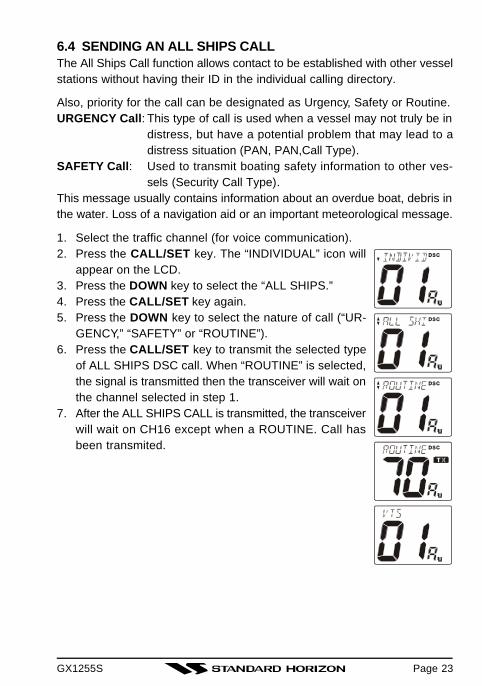
6.4 SENDING AN ALL SHIPS CALLThe All Ships Call function allows contact to be established with other vesselstations without having their ID in the individual calling directory.
Also, priority for the call can be designated as Urgency, Safety or Routine.URGENCY Call: This type of call is used when a vessel may not truly be in
distress, but have a potential problem that may lead to adistress situation (PAN, PAN,Call Type).
SAFETY Call: Used to transmit boating safety information to other ves-sels (Security Call Type).
This message usually contains information about an overdue boat, debris inthe water. Loss of a navigation aid or an important meteorological message.
1. Select the traffic channel (for voice communication).2. Press the CALL/SET key. The “INDIVIDUAL” icon will
appear on the LCD.3. Press the DOWN key to select the “ALL SHIPS.”4. Press the CALL/SET key again.5. Press the DOWN key to select the nature of call (“UR-
GENCY,” “SAFETY” or “ROUTINE”).6. Press the CALL/SET key to transmit the selected type
of ALL SHIPS DSC call. When “ROUTINE” is selected,the signal is transmitted then the transceiver will wait onthe channel selected in step 1.
7. After the ALL SHIPS CALL is transmitted, the transceiverwill wait on CH16 except when a ROUTINE. Call hasbeen transmited.
Page 23

GX1255SPage 24
6.5 RECEIVING DSC CALLSSeveral types of DSC transmissions can be received. The required actiondepends on the particular DSC type as outlined in the following examples.
NOTE
If the radio is receiving on a working channel or transmitting on a work-ing channel, DSC calls will not be received.
6.5.1 Receiving a distress call1. A distress call is received. “RECEIVED DISTRESS” will
appear on the LCD, and an emergency alarm will beheard.Channel 16 is automatically selected.
2. Press any key to stop the alarm.3. Press the UP or DOWN key to select the receiving dis-
tress data:• MMSI or Station Name • TIME (UTC)• Latitude • Longitude
NOTE
• If the received distress data does not include the position data, “NOPOSITION DATA” will scroll on the LCD.
• You must continue monitoring channel 16 as a coast station may re-quire assistance in any rescue attempt.
6.5.2 Receiving a distress relay call1. A distress relay call is received. “RECEIVED RLY” will
appear on the LCD, and an emergency alarm will beheard.Channel 16 is automatically selected.
2. Press any key to stop the alarm.3. Press the DOWN key to appear the receiving distress
data (MMSI or Station Name).
NOTE
You must continue monitoring channel 16 as a coast station may re-quire assistance in any rescue attempt.
GX1255S
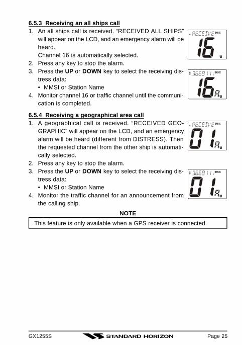
6.5.3 Receiving an all ships call1. An all ships call is received. “RECEIVED ALL SHIPS”
will appear on the LCD, and an emergency alarm will beheard.Channel 16 is automatically selected.
2. Press any key to stop the alarm.3. Press the UP or DOWN key to select the receiving dis-
tress data:• MMSI or Station Name
4. Monitor channel 16 or traffic channel until the communi-cation is completed.
6.5.4 Receiving a geographical area call1. A geographical call is received. “RECEIVED GEO-
GRAPHIC” will appear on the LCD, and an emergencyalarm will be heard (different from DISTRESS). Thenthe requested channel from the other ship is automati-cally selected.
2. Press any key to stop the alarm.3. Press the UP or DOWN key to select the receiving dis-
tress data:• MMSI or Station Name
4. Monitor the traffic channel for an announcement fromthe calling ship.
NOTE
This feature is only available when a GPS receiver is connected.
Page 25
GX1255SPage 26
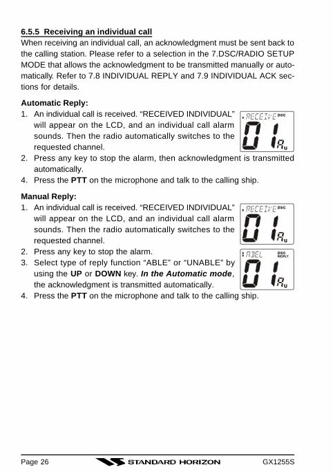
6.5.5 Receiving an individual callWhen receiving an individual call, an acknowledgment must be sent back tothe calling station. Please refer to a selection in the 7.DSC/RADIO SETUPMODE that allows the acknowledgment to be transmitted manually or auto-matically. Refer to 7.8 INDIVIDUAL REPLY and 7.9 INDIVIDUAL ACK sec-tions for details.
Automatic Reply:1. An individual call is received. “RECEIVED INDIVIDUAL”
will appear on the LCD, and an individual call alarmsounds. Then the radio automatically switches to therequested channel.
2. Press any key to stop the alarm, then acknowledgment is transmittedautomatically.
4. Press the PTT on the microphone and talk to the calling ship.
Manual Reply:1. An individual call is received. “RECEIVED INDIVIDUAL”
will appear on the LCD, and an individual call alarmsounds. Then the radio automatically switches to therequested channel.
2. Press any key to stop the alarm.3. Select type of reply function “ABLE” or “UNABLE” by
using the UP or DOWN key. In the Automatic mode,the acknowledgment is transmitted automatically.
4. Press the PTT on the microphone and talk to the calling ship.
GX1255S
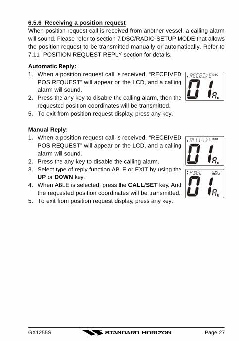
6.5.6 Receiving a position requestWhen position request call is received from another vessel, a calling alarmwill sound. Please refer to section 7.DSC/RADIO SETUP MODE that allowsthe position request to be transmitted manually or automatically. Refer to7.11 POSITION REQUEST REPLY section for details.
Automatic Reply:1. When a position request call is received, “RECEIVED
POS REQUEST” will appear on the LCD, and a callingalarm will sound.
2. Press the any key to disable the calling alarm, then therequested position coordinates will be transmitted.
5. To exit from position request display, press any key.
Manual Reply:1. When a position request call is received, “RECEIVED
POS REQUEST” will appear on the LCD, and a callingalarm will sound.
2. Press the any key to disable the calling alarm.3. Select type of reply function ABLE or EXIT by using the
UP or DOWN key.4. When ABLE is selected, press the CALL/SET key. And
the requested position coordinates will be transmitted.5. To exit from position request display, press any key.
Page 27
GX1255SPage 28
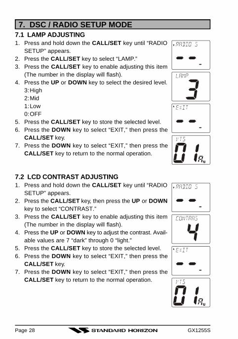
7. DSC / RADIO SETUP MODE7.1 LAMP ADJUSTING1. Press and hold down the CALL/SET key until “RADIO
SETUP” appears.2. Press the CALL/SET key to select “LAMP.”3. Press the CALL/SET key to enable adjusting this item
(The number in the display will flash).4. Press the UP or DOWN key to select the desired level.
3:High2:Mid1:Low0:OFF
5. Press the CALL/SET key to store the selected level.6. Press the DOWN key to select “EXIT,” then press the
CALL/SET key.7. Press the DOWN key to select “EXIT,” then press the
CALL/SET key to return to the normal operation.
7.2 LCD CONTRAST ADJUSTING1. Press and hold down the CALL/SET key until “RADIO
SETUP” appears.2. Press the CALL/SET key, then press the UP or DOWN
key to select “CONTRAST.”3. Press the CALL/SET key to enable adjusting this item
(The number in the display will flash).4. Press the UP or DOWN key to adjust the contrast. Avail-
able values are 7 “dark” through 0 “light.”5. Press the CALL/SET key to store the selected level.6. Press the DOWN key to select “EXIT,” then press the
CALL/SET key.7. Press the DOWN key to select “EXIT,” then press the
CALL/SET key to return to the normal operation.
GX1255S
7.3 KEY BEEP (ON or OFF)1. Press and hold down the CALL/SET key until “RADIO
SETUP” appears.2. Press the CALL/SET key, then press the UP or DOWN
key to select “KEY BEEP.”3. Press the CALL/SET key to enable adjusting this item
(The number in the display will flash).4. Press the UP or DOWN key to select “on” or “oF (off).”5. Press the CALL/SET key to store the selected setting.6. Press the DOWN key to select “EXIT,” then press the
CALL/SET key.7. Press the DOWN key to select “EXIT,” then press the
CALL/SET key to return to the normal operation.
7.4 WEATHER ALERT (ON or OFF)1. Press and hold down the CALL/SET key until “RADIO
SETUP” appears.2. Press the CALL/SET key, then press DOWN key to se-
lect “WX ALT.”3. Press the CALL/SET key to enable adjusting this item
(The number in the display will flash).4. Press the UP or DOWN key to select “on” or “oF (off).”5. Press the CALL/SET key to store the selected setting.6. Press the DOWN key to select “EXIT,” then press the
CALL/SET key.6. Press the DOWN key to select “EXIT,” then press the
CALL/SET key to return to the normal operation.
Page 29

GX1255SPage 30
7.5 CHANNEL NAME CHANGE1. Press and hold down the CALL/SET key until “RADIO
SETUP” appears.2. Press the CALL/SET key, then press DOWN key to se-
lect “CH NAME.”3. Press the CALL/SET key, then press the UP or DOWN
key to select the channel on which you wish to changea name.
4. Press the CALL/SET key to enable adjusting this item.5. Press the UP or DOWN key to select the first character
(letter, number, or symbol) in the name you wish to store,the press the CALL/SET key to move to the next char-acter.
6. If you make a mistake, press the H/L key to move back,then re-select the correct letter, number, or symbol.
7. Repeat step 5 as many times as necessary to completethe name tag (up to 12 characters).
8. Press and hold the CALL/SET key to store the newname.
9. Press the DOWN key to select “EXIT,” then press theCALL/SET key.
10. Press the DOWN key to select “EXIT,” then press theCALL/SET key to return to the normal operation.

GX1255S
7.6 TIME OFFSETSets the time difference between local time and UTC (Universal Time Coor-dinated or GMT Greenwich Mean Time). Time is displayed, if connected aGPS receiver.
1. Press and hold down the CALL/SET key until “RADIOSETUP” appears.
2. Press the CALL/SET key, then press the DOWN key toselect “TIME.”
3. Press the CALL/SET key to enable adjusting this item(The number in the display will flash).
4. Press the UP or DOWN key to select “Time Offset” fromUTC. Be sure that when selecting the offset that thedisplay shows “TIME –” for negative offset, or “TIME +”for a positive offset. Refer to Offset Time Table.See illustration below to find your offset time from UTC.If 0:0 is assigned, the time is the same as UTC.
6. Press the CALL/SET key to store the time offset.Press the DOWN key to select “EXIT,” then press theCALL/SET key.
7. Press the DOWN key to select “EXIT,” then press theCALL/SET key to return to the normal operation.
NOTE
During Daylight Saving time subtract 1 hour from the offset shown aboveand enter this offset in step 4 above.
OFFSET TIME TABLE
Page 31

GX1255SPage 32
7.7 INDIVIDUAL DIRECTORY SETUP (DSC)1. Press and hold down the CALL/SET key
until “RADIO SETUP” appears.2. Press the DOWN key to select “DSC
SETUP”.3. Press the CALL/SET key to select “IN-
DIVIDUAL DIRECTORY.”4. Press the CALL/SET key to select
“ADD.”5. Press the CALL/SET key to enable setting this item.6. Press the UP or DOWN key to select a first character of
the Station Name, then press the CALL/SET key to moveto next character.
7. Repeat step 6 as many times as necessary to completethe Station Name (up to 12 characters).
8. Press and hold the CALL/SET key to store the StationName and enable setting the MMSI ID code.
9. Press the UP or DOWN key to select the first digit of theMMSI ID code, the press the CALL/SET key to move tonext character.
10. Repeat step 9 as many times as necessary to completethe MMSI ID code (9 digits).
11. Press and hold the CALL/SET key to store the MMSI IDcode.
12. Press the DOWN key to select “EXIT,” then press theCALL/SET key.
13. Press the UP or DOWN key to select “EXIT,” then pressthe CALL/SET key to return to the normal operation.
GX1255S
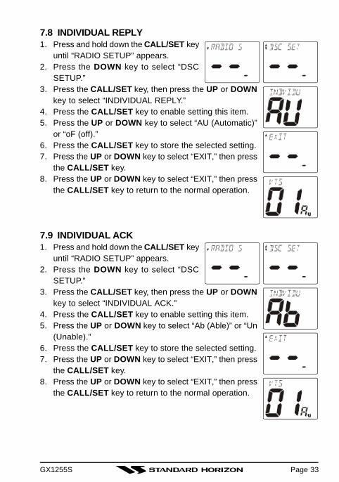
7.8 INDIVIDUAL REPLY1. Press and hold down the CALL/SET key
until “RADIO SETUP” appears.2. Press the DOWN key to select “DSC
SETUP.”3. Press the CALL/SET key, then press the UP or DOWN
key to select “INDIVIDUAL REPLY.”4. Press the CALL/SET key to enable setting this item.5. Press the UP or DOWN key to select “AU (Automatic)”
or “oF (off).”6. Press the CALL/SET key to store the selected setting.7. Press the UP or DOWN key to select “EXIT,” then press
the CALL/SET key.8. Press the UP or DOWN key to select “EXIT,” then press
the CALL/SET key to return to the normal operation.
7.9 INDIVIDUAL ACK1. Press and hold down the CALL/SET key
until “RADIO SETUP” appears.2. Press the DOWN key to select “DSC
SETUP.”3. Press the CALL/SET key, then press the UP or DOWN
key to select “INDIVIDUAL ACK.”4. Press the CALL/SET key to enable setting this item.5. Press the UP or DOWN key to select “Ab (Able)” or “Un
(Unable).”6. Press the CALL/SET key to store the selected setting.7. Press the UP or DOWN key to select “EXIT,” then press
the CALL/SET key.8. Press the UP or DOWN key to select “EXIT,” then press
the CALL/SET key to return to the normal operation.
Page 33

GX1255SPage 34
7.10 INDIVIDUAL RING1. Press and hold down the CALL/SET key
until “RADIO SETUP” appears.2. Press the DOWN key to select “DSC
SETUP.”3. Press the CALL/SET key, then press the UP or DOWN
key to select “INDIVIDUAL RINGER.”4. Press the CALL/SET key to enable setting this item.5. Press the UP or DOWN key to select ringing time of a
INDIVIDUAL CALL.4:3 minutes continuously3:15 times2:10 times1:5 times
6. Press the CALL/SET key to store the selected ringingtime.
7. Press the UP or DOWN key to select “EXIT,” then pressthe CALL/SET key.
8. Press the UP or DOWN key to select “EXIT,” then press the CALL/SETkey to return to the normal operation.
7.11 POSITION REQUEST REPLY1. Press and hold down the CALL/SET key
until “RADIO SETUP” appears.2. Press the DOWN key to select “DSC
SETUP.”3. Press the CALL/SET key, then press the UP or DOWN
key to select “POS REQUEST REPLY.”4. Press the CALL/SET key to enable setting this item.5. Press the UP or DOWN key to select “AU (Automatic)”
or “oF (off).”6. Press the CALL/SET key to store the selected setting.7. Press the UP or DOWN key to select “EXIT,” then press
the CALL/SET key.8. Press the UP or DOWN key to select “EXIT,” then press
the CALL/SET key to return to the normal operation.

GX1255S
7.12 DSC SCANNINGWhen the radio is shipped from the factory it is programmed so CH70 (theDSC channel) is scanned at all times. There is a selection in the SETUPMENU to disable the DSC SCAN. However, turning off DSC SCAN will dis-able the radio from receiving DSC calls i.e.: Individual Call, All Ships Call,Distress Call and Position Requests. If you want to use any of the functionsthe selection must be left ON.
TO CHANGE DSC SCAN METHOD:1. Press and hold down the CALL/SET key
until “RADIO SETUP” appears.2. Press the DOWN key to select “DSC
SETUP.”3. Press the CALL/SET key, then press the
UP or DOWN key to select “DSC SCAN.”4. Press the CALL/SET key to enable setting this item (The
number in the display will flash).5. Press the UP or DOWN key to select “on” or “oF (off).”6. Press the CALL/SET key to store the selected setting.7. Press the UP or DOWN key to select “EXIT,” then press
the CALL/SET key.8. Press the UP or DOWN key to select “EXIT,” then press
the CALL/SET key to return to the normal operation.
Page 35

GX1255SPage 36
7.13 USER MMSI INPUT1. Press and hold down the CALL/SET key
until “RADIO SETUP” appears.2. Press the DOWN key to select “DSC
SET.”3. Press the CALL/SET key, then press the DOWN key to
select “USER MMSI.”4. Press the CALL/SET key to enable setting this item (The
number in the display will flash).5. Press the UP or DOWN key to select first number of
your MMSI, then press the CALL/SET key to define thesetting.
6. Repeat above step to set your MMSI (up to 9 digits).When the last number of your MMSI is in place, pressand hold the CALL/SET key to store your MMSI.
7. Press the DOWN key to select “EXIT,” then press theCALL/SET key.
8. Press the UP or DOWN key to select “EXIT,” then press the CALL/SETkey to return to the normal operation.
WARNING
If the user MMSI is enabled more than 2 times, the LCD will show “ER-ROR TOO MANY ENTRIES.” The radio will have to be sent back toStandard Horizon factory Service in order to be able to program in an-other MMSI.
GX1255S
8 OPERATING PRACTICES8.1 EMERGENCY (CHANNEL 16 USE)Channel 16 is known as the Hail and Distress Channel. An emergency maybe defined as a threat to life or property. In such instances, be sure thetransceiver is on and set to CHANNEL 16. Then use the following proce-dure:
1. Press the microphone push-to-talk switch and say “Mayday, Mayday,Mayday. This is , , ” (your vessel’s name).
2. Then repeat once: “Mayday, ” (your vessel’s name).3. Now report your position in latitude/longitude, or by giving a true or mag-
netic bearing (state which) to a well-known landmark such as a naviga-tion aid or geographic feature such as an island or harbor entry.
4. Explain the nature of your distress (sinking, collision, aground, fire, heartattack, life-threatening injury, etc.).
5. State the kind of assistance your desire (pumps, medical aid, etc.).6. Report the number of persons aboard and condition of any injured.7. Estimate the present seaworthiness and condition of your vessel.8. Give your vessel’s description: length, design (power or sail), color and
other distinguishing marks. The total transmission should not exceed 1minute.
9. End the message by saying “OVER”. Release the microphone buttonand listen.
10. If there is no answer, repeat the above procedure. If there is still noresponse, try another channel.
8.2 CALLING ANOTHER VESSEL (CHANNEL 16 OR 9)Channel 16 may be used for initial contact (hailing) with another vessel.However, its most important use is for emergency messages. This channelmust be monitored at all times except when actually using another channel.It is monitored by the U.S. and Canadian Coast Guards and by other ves-sels. Use of channel 16 for hailing must be limited to initial contactonly. Calling should not exceed 30 seconds, but may be repeated 3 times at2-minute intervals. In areas of heavy radio traffic, congestion on channel 16resulting from its use as a hailing channel can be reduced significantly inU.S. waters by using channel 9 as the initial contact (hailing) channel fornon-emergency communications. Here, also, calling time should not exceed30 seconds but may be repeated 3 times at 2-minute intervals.
Page 37
GX1255SPage 38
Prior to making contact with another vessel, refer to the channel charts inthis manual, and select an appropriate channel for communications afterinitial contact. For example, Channels 68 and 69 of the U.S. VHF Charts aresome of the channels available to non-commercial (recreational) boaters.Monitor your desired channel in advance to make sure you will not be inter-rupting other traffic, and then go back to either channel 16 or 9 for your initialcontact.
When the hailing channel (16 or 9) is clear, state the name of the othervessel you wish to call and then “this is” followed by the name of yourvessel and your Station License (Call Sign). When the other vessel returnsyour call, immediately request another channel by saying “go to,” the num-ber of the other channel, and “over.” Then switch to the new channel. Whenthe new channel is not busy, call the other vessel.
After a transmission, say “over,” and release the microphone’s push-to-talk(PTT) switch. When all communication with the other vessel is completed,end the last transmission by stating your Call Sign and the word “out.” Notethat it is not necessary to state your Call Sign with each transmission, onlyat the beginning and end of the contact.
Remember to return to Channel 16 when not using another channel. Someradios automatically monitor Channel 16 even when set to other channelsor when scanning; see your Owner’s Manual.
8.3 MAKING TELEPHONE CALLSTo make a radiotelephone call, use a channel designated for this purpose,The fastest way to learn which channels are used for radiotelephone trafficis to ask at a local marina. Channels available for such traffic are designatedPublic Correspondence channels on the channel charts in this manual.Some examples for USA use are Channels 24, 25, 26, 27, 28, 84, 85, 86,and 87. Call the marine operator and identify yourself by your vessel’s name,The marine operator will then ask you how you will pay for the call (tele-phone credit card, collect, etc.) and then link your radio transmission to thetelephone lines.
The marine telephone company managing the VHF channel you are usingmay charge a link-up fee in addition to the cost of the call.
GX1255S
8.4 OPERATING ON CHANNELS 13 AND 67Channel 13 is used at docks and bridges and by vessels maneuvering inport. Messages on this channel must concern navigation only, such as meet-ing and passing in restricted waters.
Channel 67 is used for navigational traffic between vessels.
By regulation, power is normally limited to 1 Watt on these channels. Yourradio is programmed to automatically reduce power to this limit on thesechannels. However, in certain situations it may be necessary to temporarilyuse a higher power. See page 7 (H/L key) for means to temporarily overridethe low-power limit on these two channels.
8.5 PROHIBITED COMMUNICATIONSThe FCC prohibits the following communications:
• False distress or emergency messages:• Messages to “any boat” except in emergencies and radio tests;• Messages to or from a vessel on land;• Transmission while on land;• Obscene, indecent, or profane language (potential fine of $10,000).
8.6 NOAA WEATHER ALERT TESTINGIn the event of a major storm or other appreciable weather condition requir-ing vessels at sea or other bodies of water to be notified, the NOAA (Na-tional Oceanographic and Atmospheric Administration) broadcasts a 1050Hz tone that some marine VHF radios can detect. (Refer to Section 5.7“NOAA WEATER ALERT” on how to use this feature.) This tone, when de-tected, will produce a loud beep from the radio speaker to signal that aweather alert is being broadcast.
In order to test this system, the NOAA broadcasts the 1050 Hz tone everyWednesday, sometime between 11 AM and 1 PM. Any marine VHF radiothat can detect the weather alert tone, may use this test to verify that thisfeature is functioning properly.
Page 39

GX1255SPage 40
8.7 DIGITAL SELECTIVE CALLING (DSC)Digital Selective Calling is a semi-automated method of establishing a radiocall, it has been designated by the International Maritime Organization (IMO)as an international standard for establishing VHF, MF and HF radio calls. Ithas also been designated part of the Global Maritime Distress and SafetySystem (GMDSS) and it is planned that DSC will eventually replace auralwatches on distress frequencies and will be used to announce routine andurgent maritime safety information broadcasts.
This new service will allow mariners to instantly send a distress call withGPS position (when connected to the transceiver) to the US Coast Guardand other vessels within range of the transmission. DSC will also allow mari-ners to initiate or receive distress, urgency, safety and routine calls to orfrom another vessel equipped with a DSC transceiver.
8.7.1 USCG DSC WatchThe USCG has plans to upgrade its VHF National Distress System (expectedby 2005), so at the time of printing only larger vessels that are required tocarry VHF DSC radios will be able to hear your distress transmission.
8.8 MARITIME MOBILE SERVICE IDENTITY (MMSI)8.8.1 What is a MMSI?A MMSI is a nine digit number used on Marine Transceivers capable ofusing Digital Selective Calling (DSC). This number is used like a telephonenumber to selectively call other vessels.
8.9 USING DIGITAL SELECTIVE CALLING FEATURES8.9.1 Distress CallTransmits a DSC Distress message to all radios equipped to receive a DSCDistress call. Some Standard Horizon radios may be connected to a GPS toalso transmit the Latitude, Longitude of the vessel.
8.9.2 Individual CallThis feature allows the user to contact another vessel capable of using DSCand automatically switch the radio to a desired working channel. This fea-ture is similar to calling a desired vessel on CH16 and requesting them to goto another channel.
8.9.3 Urgency CallThis call should be used when a vessel may not be truly in distress, but havea potential problem that might lead to a distress situation.

GX1255S
8.9.4 Safety CallUsed to transmit boating safety information to other vessels. This messageusually contains information about an overdue boat, a derelict afloat, loss ofa navigation aid or an important meteorological message.
8.10 ADDITIONAL DIGITAL SELECTIVE CALLING INFORMATIONFor additional information the USCG has an excellent site that should bevisited at www.navcen.uscg.mil/marcoms/gmdss/dsc.html.
8.11 ABOUT VHF RADIOThe radio frequencies used in the VHF marine band lie between 156 and158 MHz with some shore stations available between 161 and 163 MHz.The marine VHF band provides communications over distances that areessentially “line of sight” (VHF signals do not travel well through objectssuch as buildings, hills or trees). Actual transmission range depends muchmore on antenna type, gain and height than on the power output of thetransmitter. On a fixed mount 25W radio transmission expected distancescan be greater than 15 miles, for a portable 5W radio transmission the ex-pected distance can be greater than 5 miles in “line of sight”.
8.12 SELECTING AN ANTENNAMarine antennas are made to radiate signals equally in all horizontal direc-tions, but not straight up. The objective of a marine antenna is to enhancethe signal toward the horizon. The degree to which this is accomplished iscalled the antenna’s gain. It is measured in decibels (dB) and is one of themajor factors in choosing an antenna. In terms of effective radiated power(ERP), antennas are rated on the basis of how much gain they have over atheoretical antenna with zero gain. A 3 foot, 3dB gain antenna representstwice as much gain over the imaginary antenna. The length of the antennayou choose, however, must also be related to the size of your boat.
Typically a 3 foot 3dB gain stainless steel whip is used on a sailboat mast.The longer 8 foot 6dB fiberglass whip is primarily used on power boats thatrequire the additional gain.
Page 41

GX1255SPage 42
8.13 COAXIAL CABLEVHF antennas are connected to the transceiver by means of a coaxial cable– a shielded transmission line. Coaxial cable is specified by it’s diameterand construction.
For runs less than 20 feet, RG-58/U, about 1/4 inch in diameter is a goodchoice. For runs over 20 feet but less than 50 feet, the larger RG-8 or RG-213/U should be used for cable runs over 50 feet RG-8 should be used. Forinstallation of the connector onto the coaxial cable refer to the figure below.
1/16''
3/4''3/4''
1 1/8''
1/8''
5/8''3/8''
Adapter
To get your coax cable through a fitting and into your boat’s interior, youmay have to cut off the end plug and reattach it later. You can do this ifyou follow the directions that come with the connector. Be sure to makegood soldered connections.

GX1255S
9 MAINTENANCEThe inherent quality of the solid-state components used in this transceiverwill provide many years of continuous use. Taking the following precautionswill prevent damage to the transceiver.
• Keep the microphone connected or the jack covered at all times to pre-vent corrosion of electrical contacts;
• Never key the microphone unless an antenna or suitable dummy load isconnected to the transceiver.
• Ensure that the supply voltage to the transceiver does not exceed 16VDC or fall below 11 VDC.
• Use only STANDARD HORIZON-approved accessories and replacementparts.
In the unlikely event of serious problems, please contact your Dealer or ourrepair facility. Address and phone numbers for this facility, as well as war-ranty information, are contained in section 11 WARRANTY.
9.1 REPLACEMENT PARTSOccasionally an owner needs a replacement mounting bracket or knob.These can be ordered from our Parts Department by writing or calling:
Marine Division of Vertex StandardUS Headquarters10900 Walker Street, Cypress, CA 90630, U.S.A.Telephone (714) 827-7600
Commonly requested parts, and their part numbers are listed below.• Power Code: T9023306• Dust Cover: RA0437900• VOL/SQL Knob Assy: RA0422200• Mounting Braket (White): RA0448900• Microphone Hanger: RA0436000
Page 43
GX1255SPage 44
9.2 FACTORY SERVICEIn the unlikely event that the radio fails to perform or needs servicing,please contact the following:
Standard Horizon Factory Service115 North Wright Brothers DriveSalt Lake City, UT 84116-2838Telephone (800) 366-4566Fax No. (801) 359-4122
An “RA” Return Authorization number is not necessary to send a product infor service. Include a brief note describing the problem along with your name,return address, phone number, and proof of purchase.

GX1255S
9.3 TROUBLESHOOTING CHART
SYMPTON
Transceiver fails topower up.
Transceiver blowsfuse when connectedto power supply.
Popping or whiningn o i s e f r o m t h espeaker while engineruns.
Sound is not emittedfrom the externalspeaker.
Receiving station re-por t low t ransmi tpower , even wi thtransceiver set to HIpower.
“HI BATTERY” or“LOW BATTERY”message is scrolledwhen the power isturned on.
Your position is notdisplayed.
PROBABLE CAUSE
No DC voltage to thetransceiver, or blownfuse.
R e v e r s e d p o w e rwires.
Engine noise.
External cable.
Antenna.
The power supply volt-age is too high or toolow.
External cable.
Setting of the GPSnavigation receiver.
REMEDY
Rotate the VOL/PWR knob clock-wise to turn on the transceiver.
Check the power cable for DC volt-age, or replace the fuse (6A 250V).Make sure the red wire is con-nected to the positive (+) batterypost, and the black wire is con-nected to the negative (-) batterypost. If the fuse still blows, con-tact your Dealer.
Reroute the DC power cablesaway from the engine. Add noisesuppressor on power cable.Change to resistive spark plugwires and/or add an alternatorwhine filter.
Check the polarity of the con-nected external cable.
Have the antenna checked or testthe transceiver with another an-tenna. If the problem persists, con-tact your Dealer for servicing.
Confirm that the connected powersupply voltage is not 17 volts orlower than 10 volts. Confirm thatthe generator has not malfunc-tioned.
Check the polarity of the con-nected external cable.Some GPS use the battery groundline for NMEA connection.
Check the output signal format ofthe GPS navigation receiver. Thisradio requires NMEA0183 formatwith GLL sentence as an outputsignal. If the GPS has a baud ratesetting make sure to select 4800and parity to NONE.
TROBLESHOOTING CHART
Page 45
GX1255SPage 46
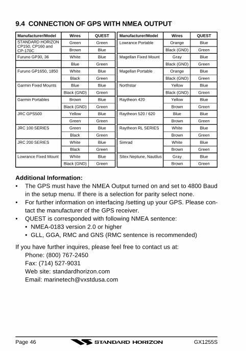
9.4 CONNECTION OF GPS WITH NMEA OUTPUT
Additional Information:• The GPS must have the NMEA Output turned on and set to 4800 Baud
in the setup menu. If there is a selection for parity select none.• For further information on interfacing /setting up your GPS. Please con-
tact the manufacturer of the GPS receiver.• QUEST is corresponded with following NMEA sentence:
• NMEA-0183 version 2.0 or higher• GLL, GGA, RMC and GNS (RMC sentence is recommended)
If you have further inquires, please feel free to contact us at:Phone: (800) 767-2450Fax: (714) 527-9031Web site: standardhorizon.comEmail: [email protected]
Manufacturer/Model
Lowrance Portable
Magellan Fixed Mount
Magellan Portable
Northstar
Raytheon 420
Raytheon 520 / 620
Raytheon RL SERIES
Simrad
Sitex Neptune, Nautilus
Wires
Orange
Black (GND)
Gray
Black (GND)
Orange
Black (GND)
Yellow
Black (GND)
Yellow
Brown
Blue
Brown
White
Brown
White
Brown
Gray
Brown
QUEST
Blue
Green
Blue
Green
Blue
Green
Blue
Green
Blue
Green
Blue
Green
Blue
Green
Blue
Green
Blue
Green
Wires
Green
Brown
White
Blue
White
Black
Blue
Black (GND)
Brown
Black (GND)
Yellow
Green
Green
Black
White
Black
White
Black (GND)
Manufacturer/Model
Furuno GP30, 36
Furuno GP1650, 1850
Garmin Fixed Mounts
Garmin Portables
JRC GPS500
JRC 100 SERIES
JRC 200 SERIES
Lowrance Fixed Mount
QUEST
Green
Blue
Blue
Green
Blue
Green
Blue
Green
Blue
Green
Blue
Green
Blue
Green
Blue
Green
Blue
Green
STANDARD HORIZONCP150, CP160 andCP-170C

GX1255S
10. CHANNEL ASSIGNMENTSTables on the following columns list the VHF Marine Channel assignmentsfor U.S.A. and International use. Below are listed some data about the charts.
1. VTS. Where indicated, these channels are part of the U.S. Coast Guard’sVessel Traffic System.
2. Alpha channel numbers, that is, channel numbers followed by the letterA (such as Channel 07A) are simplex channels on the U.S.A. or Cana-dian channel assignments whose counterparts in the International as-signments are duplex channels. International channels do not use “al-pha” numbers. If you call the Coast Guard on Channel 16, they will some-times ask you to “go to channel 22 Alpha.” This is a channel assignedto U.S.A, and Canadian Coast Guards for handling distress and othercalls. If your radio is set for International operation you will go to Chan-nel 22 instead of 22A, and will not be able to communicate with theCoast Guard. To use Channel 22A, your radio must be set for USA orCanada operation, usually by a U/I/C (USA/International/Canada) con-trol or combination of controls. Channel 22 (without an “A”) is an Inter-national duplex channel for port operations. Some radios indicate an“A” adjacent to the alpha channels on the display; on others “alpha” isnot indicated but the proper channel is selected based on the U/I/C set-ting.
3. Bridge-to-Bridge channels (for example, Channel 13) are for use by bridgeoperators on intercoastal waterways and rivers. It is also used by marinevessels in the vicinity of these bridges for navigation and for communi-cating with the bridge operators. Note that a limit of 1 Watt is specifiedfor these channels. See page xx for additional information.
4. The S/D column on the chart indicates either S (simplex) or D (duplex).Simplex means transmitting and receiving on the same frequency. Onlyone party at a time can talk, unlike a telephone. Be sure to say “over”and release your microphone push-to-talk switch at the end of each trans-mission. Duplex operation involves the use of one frequency for trans-mitting and a separate frequency for receiving. On channels specifiedas duplex on the charts, correct mode of operation is established auto-matically by your radio when you select a channel; you cannot changethe mode. And you still must release the push-to-talk switch after eachtransmission in order to listen to the radio.
Page 47

GX1255SPage 48
5. Channels normally used by recreational boaters are those that includethe term “non-commercial” in the Channel Use column of the chart. Someof these are shared with other users and some are used only in certaingeographic regions.
6. Marine vessels equipped with VHF radios are required to monitorChannel 16.
VHF MARINE CHANNEL CHARTCH U C I S/D TX RX CHANNEL USE01 X X D 156.050 160.650 Public Correspondence (Marine Operator)
01A X S 156.050 Port Operation and Commercial. VTS in selected areas02 X X D 156.100 160.700 Public Correspondence (Marine Operator)03 X X D 156.150 160.750 Public Correspondence (Marine Operator)
03A X S 156.150 US Government only, Coast Guard04 X D 156.200 160.800 Public Correspondence (Marine Operator),
Port operation, ship movement04A X S 156.200 Pacific coast: Coast Guard, East Coast:
Commercial fishing05 X D 156.250 160.850 Public Correspondence (Marine Operator),
Port operation, ship movement05A X X S 156.250 Port operation. VTS in Seattle06 X X X S 156.300 Inter-ship Sefety07 X D 156.350 160.950 Public Correspondence (Marine Operator),
Port operation, ship movement07A X X S 156.350 Commercial08 X X X S 156.400 Commercial (Inter-ship only)09 X X X S 156.450 Boater Calling channel, Commercial & Non-commercial
(Recreational)10 X X X S 156.500 Commercial11 X X X S 156.550 Commercial. VTS in selected areas.12 X X X S 156.600 Port operation. VTS in selected areas.13 X X X S 156.650 Inter-ship Navigation Safety (Bridge-to-bridge)14 X X X S 156.700 Port operation. VTS in selected areas.15 X S - - - 156.750 Environmental (Receive only)15 X X S 156.750 Commercial, non-commercial, ship movement (1 W)16 X X X S 156.800 International Distress, Safety and Calling17 X X X S 156.850 State Controlled (1 W)18 X D 156.900 161.500 Port operation, ship movement
18A X X S 156.900 Commercial19 X D 156.950 161.550 Port operation, ship movement
19A X S 156.950 US: Commercial19A X S 156.950 Coast Guard20 X X X D 157.000 161.600 Canadian Coast Guard Only,
International: port operations and shipment20A X S 157.000 Port operation21 X D 157.050 161.650 Port operation, ship movement
21A X X S 157.050 U.S. Government Only, Canadian Coast Guard22 X D 157.100 161.700 Port operation, ship movement
22A X X S 157.100 US and Canadian Coast Guard Liaison and MaritimeSafety Information Broadcasts announced on channel 16

GX1255S
VHF MARINE CHANNEL CHARTCH U C I S/D TX RX CHANNEL USE23 X X D 157.150 161.750 Public Correspondence (Marine Operator)
23A X S 157.150 U.S. Government Only24 X X X D 157.200 161.800 Public Correspondence (Marine Operator)25 X X X D 157.250 161.850 Public Correspondence (Marine Operator)26 X X X D 157.300 161.900 Public Correspondence (Marine Operator)27 X X X D 157.350 161.950 Public Correspondence (Marine Operator)28 X X X D 157.400 162.000 Public Correspondence (Marine Operator)60 X X D 156.025 160.625 Public Correspondence (Marine Operator)61 X D 156.075 160.675 Public Correspondence (Marine Operator),
Port operation, ship movement61A X X S 156.075 U.S. Govermrnt Only, Canadian Coast Guard-Pacific
Coast, Commercial Fishing-East Coast62 X D 156.125 160.725 Public Correspondence (Marine Operator),
Port operation, ship movement62A X S 156.125 Public Coast: Coast Guard;
East Coast: commercial fishing only63 X D 156.175 160.775 Public Correspondence (Marine Operator),
Port operation, ship movement63A X S 156.175 Port Operation and Commercial. VTS in selected areas.64 X X D 156.225 160.825 Public Correspondence (Marine Operator),
Port operation, ship movement64A X X S 156.225 U.S. Government Only, Canadian Commercial Fishing65 X D 156.275 160.875 Public Correspondence (Marine Operator),
Port operation, ship movement65A X X S 156.275 Port Opeations66 X D 156.325 160.925 Public Correspondence (Marine Operator),
Port operation, ship movement66A X X S 156.325 Port Operations67 X X X S 156.375 US: Commercial. Used for Bridge-to-bridge communi-
cations in lower Mississippi River. Inter-ship only,Canada: Commercial fishing, S&R
68 X X X S 156.425 Non-commercial (Recreational)69 X X X S 156.475 US: Non-commercial (Recreational),
Canada: Commercial fishing only,International: Inter-ship, Port opertions and Ship movement
70 X X X S 156.525 Digital selective calling (voice communications not allowed)71 X X X S 156.575 US, Canada: Non-commercial (Recreational),
International: Port opertions and Ship movement72 X X X S 156.625 Non-commercial (Inter-ship only)73 X X X S 156.675 US: Port Operations, Canada: Commercial fishing only,
International: Inter-ship, Port opertions and Ship movement74 X X X S 156.725 US: Port Operations, Canada: Commercial fishing only,
International: Inter-ship, Port opertions and Ship movement75 X S 156.775 Port Operations (Inter-ship only) (1W)76 X S 156.825 Port Operations (Inter-ship only) (1W)77 X X S 156.875 Port Operations (Inter-ship only) (1W)77 X S 156.875 Port Operations (Inter-ship only)78 X D 156.925 161.525 Public Correspondence (Marine Operator),
Port operation, ship-movement78A X X S 156.925 Non-commercial (Recreational)
Page 49

GX1255SPage 50
VHF MARINE CHANNEL CHARTCH U C I S/D TX RX CHANNEL USE79 X D 156.975 161.575 Port operation and Ship movement
79A X X S 156.975 Commercial80 X D 157.025 161.625 Port operation, ship movement
80A X X S 157.025 Commercial81 X D 157.075 161.675 Port operation, ship movement
81A X X S 157.075 U.S. Government Only -Environmental protection operations.
82 X D 157.125 161.725 Public Correspondence (Marine Operator),Port operation, ship movement
82A X X S 157.125 U.S. Government Only, Canadian Coast Guard Only83 X X D 157.175 161.775 Canadian Coast Guard Only
83A X X S 157.175 U.S. Government Only, Canadian Coast Guard Only83 X X D 157.175 161.775 Public Correspondence (Marine Operator)84 X X X D 157.225 161.825 Public Correspondence (Marine Operator)85 X X X D 157.275 161.875 Public Correspondence (Marine Operator)86 X X X D 157.325 161.925 Public Correspondence (Marine Operator)87 X X X D 157.375 161.975 Public Correspondence (Marine Operator)88 X X X D 157.425 162.025 Public Correspondence (ship-to-coast)
88A X S 157.425 Commercial, Inter-ship OnlyWX01 X X X D - - - 162.550 Weather (receive only)WX02 X X X D - - - 162.400 Weather (receive only)WX03 X X X D - - - 162.475 Weather (receive only)WX04 X X X D - - - 162.425 Weather (receive only)WX05 X X X D - - - 162.450 Weather (receive only)WX06 X X X D - - - 162.500 Weather (receive only)WX07 X X X D - - - 162.525 Weather (receive only)WX08 X X X D - - - 161.650 Weather (receive only)WX09 X X X D - - - 161.775 Weather (receive only)WX10 X X X D - - - 163.275 Weather (receive only)
The above BOLD channels are not for use of the general public in U.S. waters, unless properauthorization is given.
GX1255S
11. WARRANTYMarine Products Limited Warranty
STANDARD HORIZON (a division of VERTEX STANDARD) warrants, to theoriginal purchaser only, each new Marine Communications Product (“Prod-uct”) manufactured and/or supplied by STANDARD HORIZON against de-fects in materials and workmanship under normal use and service for aperiod of time from the date of purchase as follows:
Fixed Mount and Portable Transceivers1 year - if purchased before 01/01/913 years - if purchased between 01/01/91 and 01/01/943 years Waterproof - if purchased after 01/01/94
Loud hailers1 year - if purchased before 01/01/913 years - if purchased after 01/01/91
Associated Chargers1 year - if purchased before 01/01/913 years - if purchased after 01/01/91
Associated Batteries - 18 months. Note: Batteries will be deemed deflec-tive only if storage capacity drops below 80% of rated capacity or if leakagedevelops.
Associated Accessories - 1 year. Includes: Microphones/Handsets, Exter-nal Speakers, Antennas, Carrying Accessories, Power Supplies, and Sig-naling Boards.
To receive warranty service, the purchaser must deliver the Product, trans-portation and insurance prepaid, to STANDARD HORIZON (a division ofVERTEX STANDARD), 115 North Wright Brothers Dr, Salt Lake City, Utah84116-2838. Include proof of purchase indicating model. serial number, anddate of purchase. STANDARD HORIZON will return the Product to the pur-chaser freight prepaid. Products purchased prior to January 1, 1991 willbear the STANDARD HORIZON warranty terms in effect prior to that date.
In the event of a defect, malfunction or failure of the Product during thewarranty period, STANDARD HORIZON’s liability for any breach of contractor any breach of express or implied warranties in connection with the sale ofProducts shall be limited solely to repair or replacement, at its option, of theProduct or part(s) therein which, upon examination by STANDARD HORI-
Page 51

GX1255SPage 52
ZON, appear to be defective or not up to factory specifications. STANDARDHORIZON may, at its option, repair or replace parts or subassemblies withnew or reconditioned parts and subassemblies. Parts thus repaired or re-placed are warranted for the balance of the original applicable warranty.
STANDARD HORIZON will not warrant installation, maintenance or serviceof the Products. In all instances, STANDARD HORIZON’s liability for dam-ages shall not exceed the purchase price of the defective Product.
This warranty only extends to Products sold within the 50 States of the UnitedStates of America and the District of Columbia.
STANDARD HORIZON will pay all labor to repair the product and replace-ment parts charges incurred in providing the warranty service except wherepurchaser abuse or other qualifying exceptions exist. The purchaser mustpay any transportation expenses incurred in returning the Product to STAN-DARD HORIZON for service.
This limited warranty does not extend to any Product which has been sub-jected to misuse, neglect, accident, incorrect wiring by anyone other thanSTANDARD HORIZON, improper installation, or subjected to use in viola-tion of instructions furnished by STANDARD HORIZON, nor does this war-ranty extend to Products on which the serial number has been removed,defaced, or changed. STANDARD HORIZON cannot be responsible in anyway for ancillary equipment not furnished by STANDARD HORIZON whichis attached to or used in connection with STANDARD HORIZON’s Products,or for the operation of the Product with any ancillary equipment, and all suchequipment is expressly excluded from this warranty. STANDARD HORIZONdisclaims liability for range, coverage, or operation of the Product and ancil-lary equipment as a whole under this warranty. STANDARD HORIZON re-serves the right to make changes or improvements in Products, during sub-sequent production, without incurring the obligation to install such changesor improvements on previously manufactured Products.
The implied warranties which the law imposes on the sale of this Productare expressly LIMITED, in duration, to the time period specified above. STAN-DARD HORIZON shall not be liable under any circumstances for conse-quential damages resulting from the use and operation of this Product, orfrom the breach of this LIMITED WARRANTY, any implied warranties, orany contract with STANDARD HORIZON. IN CONNECTION WITH THESALE OF ITS PRODUCTS, STANDARD HORIZON MAKES NO WARRAN-

GX1255S
TIES, EXPRESS OR IMPLIED AS TO THE MERCHANTABILITY OR FIT-NESS FOR A PARTICULAR PURPOSE OR OTHERWISE, EXCEPT ASEXPRESSLY SET FORTH HEREIN.
Some states do not allow the exclusion or limitation of incidental or conse-quential damages, or limitation on how long an implied warranty lasts, sothe above limitations or exclusions may not apply. This warranty gives spe-cific legal rights, and there may be other rights which may vary from state tostate.
ONLY PRODUCTS SOLD ON OR AFTER JANUARY 1, 1991 ARE COV-ERED UNDER THE TERMS OF THIS LIMITED WARRANTY.
Page 53

GX1255SPage 54
ON-LINE WARRANTY REGISTRATIONTHANK YOU for buying STANDARD HORIZON (a division of Vertex Stan-dard) products! We are confident your new radio will serve your needs formany years!
Please visit www.standardhorizon.com to register the QUEST Marine VHF.It should be noted that visiting the Web site from time to time may be benefi-cial to you, as new products are released they will appear on the STAN-DARD HORIZON Web site. Also a statement regarding product supportshould be added to the manual.
Product Support Inquiries
If you have any questions or comments regarding the use of the QUEST,you can visit the STANDARD HORIZON Web site to send an E-Mail or con-tact the Product Support team at (714) 827-7600 or (800) 767-2450 M-F7:00-5:00PST.
In addition to the warranty, STANDARD HORIZON includes a lifetime “flatrate” program to provide service after the warranty period has expired. If youwish to obtain the flat rate price for out-of-warranty repair, you must includethe information on the Owner’s Record with the unit when you return it toyour Dealer or to STANDARD HORIZON.
Lifetime Flat Rate Service Program: For the original Owner only, for thelifetime of the unit, STANDARD HORIZON will repair the unit to original speci-fications.
Note: The flat rate amount is payable by the Owner only if STANDARD HO-RIZON or the STANDARD HORIZON Dealer determines that a repair isneeded. After the repair, a 90-day warranty will be in effect from the date ofreturn of the unit to the Owner.
This service program is not available for equipment which has failed as aresult of neglect, accident, breakage, misuse, improper installation or modi-fication, or water damage (depending on the product).

GX1255S Page 55
12 SPECIFICATIONSPerformance specifications are nominal, unless otherwise indicated, andare subject to change without notice.
12.1 GENERALChannels .............................................. All USA, International and CanadianInput Voltage ......................................................................... 13.8 VDC ±20%Current Drain
Standby...............................................................................................0.5 AReceive ...............................................................................................1.5 ATransmit .................................................................... 5.0 A (Hi); 1.5 A (Lo)
Dimensions ................................................ 2-1/2” H x 6-5/16” W x 6-5/16” D(64 H x 160 W x 160 D mm)
Flush-Mount Dimensions ................................... 2” H x 5-5/16” W x 5-1/8” D(50 H x 136 W x 130 D mm)
Weight ........................................................................................ 2.2 lbs (1 kg)
12.2 TRANSMITTERFrequency Range ................................................... 156.025 to 157.425 MHzRF Output ........................................................................ 25 W (Hi); 1 W (Lo)Conducted Spurious Emissions ..................................80 dB (Hi); 60 dB (Lo)Audio Response ...............................................within +1/-3 of a 6 dB/octave
pre-emphasis characteristic at 300 to 3000 HzAudio Distortion ......................................................................................... 5 %Modulation ....................................................... 16K0G3E, for DSC 16K0G2BFrequency Stability (-20°C to +50°C) ............................................ ±0.0005%FM Hum and Noise ................................................................................ 50 dB
12.3 RECEIVERFrequency Range ................................................... 156.050 to 163.275 MHzSensitivity
20 dB Quieting .............................................................................. 0.35 µV12 dB SINAD ................................................................................. 0.25 µVSquelch Sensitivity (Threshold) ................................................... 0.13 µV
Modulation Acceptance Bandwidth .................................................. ±7.5 kHzSelectivity
Spurious and Image Rejection ....................................................... -70 dBIntermodulation and Rejection at 12 dB SINAD ........................... -70 dB
Audio Output ............................................................................................. 4 WAudio Response ............................................. within + 2/–8 of a 6 dB/octave
de-emphasis characteristic at 300 to 3000 HzFrequency Stability (-20°C to +50°C) ........................................... ±0.0005 %Channel Spacing ................................................................................. 25 kHzDSC Format ............................................................................... RTCMSC101

GX1255SPage 56
MEMO

GX1255S Page 57
MEMO

GX1255S
Marine Division of VERTEX STANDARDUS Headquarters10900 Walker Street, Cypress, CA 90630, U.S.A.
WWW. standardhorizon.com
Copyright 2002VERTEX STANDARD CO., LTD.All rights reserved.
No portion of this manualmay be reproducedwithout the permission ofVERTEX STANDARD CO., LTD.
0206u-0K
E M 0 0 1 N 1 0 0