Embed Size (px)
Citation preview

The continuous Vee-Wire® slot design allows for lower entrance velocity of the water, reducing encrustation rates. The slot design also resists plugging and prevents sand from damaging pumps.
Stainless Steel Water Well Screens and AccessoriesJohnson Screens is one of the largest manufacturers of stainless steel water well screens in the world. With a high open area, allowing for better access to the entire formation around the screen; fines and drilling fluid are removed quickly and completely, resulting in a better well development.
Less Maintenance
The high open area of the Vee-Wire well screen allows for water to enter the well freely, resulting in minimal drawdown and less energy usage by a pump.
Pumping Costs
• Screens designed to site-specific yield requirements and aquifer characteristics• Screen slot opening selected from formation sand sample analysis • Wire and rod construction to deliver required strength for the specified well depth• Stainless material selected to maximize corrosion resistance for water chemistry• Wide variety of fittings to facilitate secure and efficient installation
Optimal Performance Through
Sand Control The water well screen is a key component of the sand control system, either as an integral component of the gravel pack, or as a standalone provider of sand control. Patented Vee-Wire technology and welded construction, help to prevent well screen failure by better controlling the sand.
Technical support and design assistance• Sand analysis of formation
materials• Screen size recommendations• Screen installation suggestions• Well construction consultation
Technical staff includes: design engineers, welders, technical support personnel and sales engineers who have been on the factory floor, presented in classrooms and technical seminars, set and pulled screens and run pumping test.
A brand of Aqseptence Group
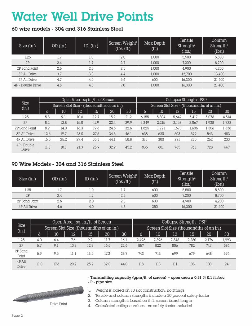
Water Well Drive Points
Size (in.) OD (in.) ID (in.) Screen Weight1 (lbs./ft.)
Max Depth(ft.)
Tensile Strength2
(lbs.)
Column Strength3
(lbs.)1.25 1.7 1.0 2.0 1,000 5,500 5,8002P 2.4 1.7 2.7 1,000 7,200 8,700
2P Sand Point 2.6 2.0 2.5 1,000 4,900 4,2003P All Drive 3.7 3.0 4.4 1,000 12,700 13,4004P All Drive 4.7 4.0 5.6 600 16,300 21,400
4P - Double Drive 4.8 4.0 7.0 1,000 16,300 21,400
Size(in.)
Open Area - sq in./ft .of Screen Collapse Strength - PSI4
Screen Slot Size - (thousandths of an in.) Screen Slot Size - (thousandths of an in.)6 10 12 15 20 30 6 10 12 15 20 30
1.25 5.8 9.1 10.6 12.7 15.9 21.2 6,155 5,804 5,642 5,417 5,078 4,5142P 8.2 12.8 15.0 17.9 22.4 29.9 2,349 2,215 2,153 2,067 1,938 1,722
2P Sand Point 8.9 14.0 16.3 19.6 24.5 32.6 1,825 1,721 1,673 1,606 1,506 1,3383P All Drive 12.6 19.7 23.0 27.6 34.5 46.1 638 620 603 579 543 4834P All Drive 16.0 25.2 29.4 35.3 44.1 58.8 318 300 291 280 262 2334P - Double
Drive 11.3 18.1 21.3 25.9 32.9 45.2 835 801 785 763 728 667
60 wire models - 304 and 316 Stainless Steel
90 Wire Models - 304 and 316 Stainless Steel
Size (in.) OD (in.) ID (in.) Screen Weight1
(lbs./ft.)Max Depth
(ft.)
Tensile Strength2
(lbs.)
Column Strength3
(lbs.)1.25 1.7 1.0 1.7 600 5,500 5,8002P 2.4 1.7 2.3 600 7,200 8,700
2P Sand Point 2.6 2.0 2.0 600 4,900 4,2004P All Drive 4.6 4.0 4.8 250 16,300 21,400
Size(in.)
Open Area - sq. in./ft. of Screen Collapse Strength - PSI4
Screen Slot Size (thousandths of an in.) Screen Slot Size (thousandths of an in.)6 10 12 15 20 30 6 10 12 15 20 30
1.25 4.0 6.4 7.6 9.2 11.7 16.1 2,496 2,396 2,348 2,280 2,176 1,9932P 5.7 9.1 10.7 12.9 16.5 22.6 857 822 806 782 747 684
2P Sand Point
5.9 9.5 11.1 13.5 17.2 23.7 743 713 699 679 648 594
4P All Drive
11.0 17.6 20.7 25.2 32.0 44.0 118 113 111 108 103 94
Drive Point
- Transmitting capacity (gpm/ft. of screen) = open area x 0.31 @ 0.1 ft./sec - P - pipe size
1. Weight is based on 10 slot construction, no fittings2. Tensile and column strengths include a 30 percent safety factor3. Column strength is based on 5 ft. screen barrel length4. Calculated collapse values - no safety factor included
Page 2

End Fitting and Screen Connection OptionsThe majority of well screen installations involve at least a few standard fitting combinations.
Telescope size screens typically use a Figure K packer on the screen top and a welded or threaded plate bottom. Pipe size screens attach directly to the casing and usually have plate bottoms.
Johnson Screens has several fittings and accessories, such as centralizers, shale traps and connecting fittings for quick delivery. Options include:• Flush threads (Sch. 40 and Sch. 80)• NPT threads• Weld rings• API couplers• Plate bottom• Threaded point• Threaded cap /plugs• Locking caps• Bail hooks• Weld ring x weld ring• Weld ring x collar• PVC to stainless steel adapter• Quickloc®
• Shur-A-Lock®
• ShurGrip®
Centralizer Figure TF Washdown
Figure K Packer
JSLFittings
R & L Threaded Couplings
R & L Threaded Nipples
Back Pressure Valves Wash Plugs
Di-Electric Coupling Flush Thread
Shale Trap
Drive Point
Page 3

Small Diameter Stainless Steel Well ScreensWater Well and Environmental Screens 60 Wire Construction 304 and 316 Stainless Steel
Size(in.)
OD(in.)
ID(in.)
Screen Weight1
(lbs./ft.)
Max Depth(ft.)
Tensile Strength2
(lbs.)
Recom. Hang
Weight3 (lbs.)
Column Strength4
(lbs.)
1.25 1.7 1.1 1.8 1,000 4,200 2,100 3,1002P* 2.5 1.99** 1.9 1,000 2,000 1,000 1,500
2P/3T 2.6 2.0 2.2 1,000 3,400 1,700 2,6002.5P 3.0 2.4 2.6 1,000 4,200 2,100 3,1003P* 3.6 2.9 2.9 1,000 4,200 2,100 3,100
3P/4T 3.7 3.1 3.0 1,000 4,200 2,100 3,1004P* 4.6 4.0** 3.7 600 4,800 2,400 3,700
4P/5T 4.7 4.1 3.8 600 4,800 2,400 3,700
5P/6T 5.6 5.0 4.5 400 5,600 2,800 4,200
Size (in.)
Open Area - sq. in./ft. of Screen Collapse Strength5 - PSIScreen Slot Size
(thousandths of an in.)Screen Slot Size
(thousandths of an in.)7 10 12 20 30 40 50 7 10 12 20 30 40 50
1.25 6.9 9.4 10.9 16.4 21.9 26.2 29.8 5,901 5,648 5,491 4,942 4,393 3,954 3,5942P* 9.7 13.3 15.5 23.3 31.0 37.2 42.3 2,094 2,004 1,948 1,754 1,559 1,403 1,275
2P/3T 10.1 13.8 16.1 24.1 32.2 38.6 43.9 1,883 1,802 1,752 1,577 1,402 1,262 1,1472.5P 11.9 16.2 18.9 28.4 37.8 45.4 51.6 1,164 1,114 1,083 975 867 780 7093P* 14.0 19.1 22.3 33.5 44.6 53.5 60.8 713 682 663 597 531 478 434
3P/4T 14.5 19.9 23.2 34.8 46.4 55.6 63.2 635 608 591 532 473 426 3874P* 17.9 24.5 28.6 42.9 57.2 68.6 78.0 340 326 317 285 253 228 207
4P/5T 18.6 25.4 29.6 44.4 59.2 71.0 80.7 307 294 286 257 229 206 1875P/6T 22.1 30.2 35.2 52.9 70.5 84.6 96.1 182 174 170 153 136 122 111
* Alternate constructions for water well and environmental** ID confirmed clear for environmental with Sch. 40 fittings only (Sch. 80 is smaller)
1. Weight is based on 10 slot construction, no fittings2. Tensile and column strengths include a 30 percent safety factor3. Recommended hang weight is 50 percent of calculated tensile strength4. Column strength is based on 5 ft. screen barrel length5. Calculated collapse values - no safety factor included
• Transmitting capacity (gpm/ft. of screen) = open area x 0.31 @ 0.1 ft./.sec• P - pipe size, T - telescope
Notes:
Page 4

Water Well and Environmental Screens 90 Wire Construction 304 and 316
Size (in.) OD: (in.) ID: (in.)Screen Weight1 (lbs/ft.)
Max Depth (ft.)
Tensile Strength2
(lbs.)
Recom. Hang
Weight3 (lbs.)
Column Strength4
(lbs.)
1.25 1.7 1.1 1.5 600 4,200 2,100 3,1002P* 2.4 1.99** 1.5 600 2,000 1,000 1,500
2P/3T 2.5 2.0 1.7 600 3,400 1,700 2,6002.5P 3.0 2.4 2.1 600 4,200 2,100 3,1003P* 3.5 2.9 2.3 600 4,200 2,100 3,100
3P/4T 3.7 3.1 2.4 600 4,200 2,100 3,1004P* 4.5 4.0** 2.9 250 4,800 2,400 3,700
4P/5T 4.7 4.1 3.0 250 4,800 2,400 3,7005P/6T 5.6 5.0 3.5 100 5,600 2,800 4,200
Size (in.)Open Area - sq in./ft. of Screen Collapse Strength5 - PSI
Screen Slot Size (thousandths of an in.) Screen Slot Size (thousandths of an in.)7 10 12 20 30 40 50 7 10 12 20 30 40 50
1.25 4.6 6.4 7.6 11.7 16.1 19.8 22.1 2,343 2,272 2,227 2,063 1,890 1,743 1,618
2P* 6.6 9.2 10.8 16.7 22.9 28.2 32.7 817 792 776 719 659 608 564
2P/3T 6.9 9.6 11.2 17.4 23.9 29.3 34.0 724 702 688 637 585 538 500
2.5P 8.1 11.3 13.3 20.5 28.1 34.6 40.1 443 429 421 390 357 330 306
3P* 9.6 13.3 15.7 24.2 33.3 40.9 47.5 269 261 255 237 217 200 186
3P/4T 10.0 13.9 16.3 25.2 34.6 42.6 49.4 239 232 227 211 193 178 165
4P* 12.4 17.1 20.2 31.1 42.8 52.6 61.0 127 123 121 112 102 94 88
4P/5T 12.8 17.7 20.9 32.2 44.3 54.5 63.2 114 111 109 101 92 85 79
5P/6T 15.3 21.2 24.9 38.5 52.8 65.0 75.4 67 65 64 59 54 50 47
* Alternate constructions for water well and environmental** ID confirmed clear for environmental with Sch. 40 fittings only (Sch. 80 is smaller)
1. Weight is based on 10 slot construction, no fittings2. Tensile and column strengths include a 30 percent safety factor3. Recommended hang weight is 50 percent of calculated tensile strength4. Column strength is based on 5 ft. screen barrel length5. Calculated collapse values - no safety factor included
• Transmitting capacity (gpm/ft. of screen) = open area x 0.31 @ 0.1 ft./.sec• P - pipe size, T - telescope
Notes:
Page 5

Free-Flow 304 Stainless Steel ScreensLarge Diameter Free-Flow Screens: Sizes 6P - 16T
1. Based on 0.030 in. slot size (collapse values contain no safety factor)
2. Recommended hang weight is 50 percent of the calculated tensile strength
3. Transmitting capacity in gpm/ft. of screen = open area x 0.31 @ 0.1 ft./sec.
Telescope size screens install through the casing and usually have a Figure K packer as the upper fitting. Pipe size screens (right) usually have weld rings at each end and attach directly to the casing.
Size(in.)
Max Depth
(ft.)
OD:(in.)
ID(in.)
Weight1 (lbs./ft.)
Recom. Hang
Weight2 (lbs.)
Collapse Strength1
(PSI)
Intake Area3 - sq. in./ft. of Screen
Screen Slot Size (thousandths of an in.)
10 20 30 40 50 60 80 100
6P
100 6.6 6.1 4.5 4,315 83 36 62 83 100 113 124 142 156
250 6.7 6.1 4.8 4,315 187 20 37 52 65 76 86 103 117
600 6.7 5.9 6.0 8,813 185 20 37 52 65 76 86 103 1171,000 6.8 5.9 9.0 10,987 681 16 30 43 54 64 73 89 1021,600 6.9 5.9 14.2 16,498 870 16 30 43 55 65 74 90 104
8T
250 7.6 6.8 7.1 11,016 130 23 45 59 73 86 97 116 132600 7.6 6.8 6.1 10,404 487 18 34 48 60 72 82 100 115
1,000 7.6 6.7 10.5 13,734 485 18 34 48 60 72 82 100 1151,600 7.7 6.7 16.6 20,622 622 18 34 48 61 72 83 101 116
8P
250 8.7 7.9 8.0 12,118 84 26 48 67 84 98 111 133 151600 8.7 7.9 10.0 11,444 323 21 39 55 69 82 94 114 131
1,000 8.8 7.9 11.9 15,107 315 21 39 55 70 83 95 115 1331,600 8.9 7.9 18.8 22,684 406 21 39 56 70 84 96 116 134
10T250 9.5 8.7 9.0 14,321 65 28 53 74 92 108 122 146 166
1,000 9.5 8.6 11.2 13,525 250 22 42 60 75 89 102 125 1431,600 9.6 8.6 21.1 26,809 317 23 43 61 76 91 104 126 145
10P600 10.7 9.9 12.5 14,566 173 25 48 68 85 101 116 141 162
1,000 10.8 9.9 20.1 19,228 227 25 48 68 86 102 116 141 1631,600 11.0 9.9 28.3 28,871 523 27 51 72 91 108 123 149 171
12T600 11.3 10.4 13.5 16,646 149 27 50 71 90 107 122 148 170
1,000 11.5 10.4 26.8 21,974 463 28 53 75 95 112 128 156 1791,600 11.5 10.4 30.5 32,995 453 29 54 76 96 113 129 157 180
12P
250 12.7 11.8 14.7 16,646 104 30 57 80 101 120 137 167 192600 12.7 11.8 16.2 16,646 138 30 57 80 101 120 137 167 192
1,000 12.9 11.8 29.2 21,974 325 32 60 85 107 127 144 175 2011,600 13.0 11.8 33.0 32,995 319 32 60 85 108 127 145 176 202
14T
250 12.5 11.6 13.6 13,525 111 29 55 78 99 117 134 163 188600 12.5 11.6 19.6 13,525 147 29 55 78 99 117 134 163 188
1,000 12.6 11.5 27.4 17,854 347 31 59 83 105 124 141 171 1971,600 12.7 11.5 30.5 26,809 341 31 59 84 105 125 142 173 198
14P/16T
250 14.0 13.0 15.5 16,126 79 33 62 88 111 132 151 183 211600 14.1 13.0 28.5 16,126 249 35 66 93 117 138 158 192 220
1,000 14.1 12.9 31.1 21,288 248 35 66 93 117 139 158 192 2201,600 14.3 12.9 38.6 31,964 356 38 72 101 126 149 170 205 234
1. Based on 0.030 in. slot size (collapse values contain no safety factor)
2. Recommended hang weight is 50 percent of the calculated tensile strength
3. Transmitting capacity in gpm./ft. of screen = open area x 0.31 @ 0.1 ft./sec.
• Screens are available in up to 40 ft. lengths of continuously wrapped screen with no mid-weld
• Technical information is available upon request for 316 stainless steel screens
• P - pipe size, T - telescope• For application depths > 1,600 ft., contact Technical Support
Notes:
Page 6
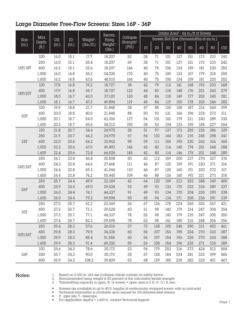
Large Diameter Free-Flow Screens: Sizes 16P - 36P
Size(in.)
Max Depth:
(ft.)
OD: (in.)
ID:(in.)
Weight1: (lbs./ft.)
Recom. Hang
Weight2: (lbs.)
Collapse Strength1
(PSI)
Intake Area3 - sq in./ft of ScreenScreen Slot Size (thousandths of an in.)
10 20 30 40 50 60 80 100
16P/18T
100 16.0 15.1 17.7 18,207 52 38 71 101 127 151 173 210 242250 16.0 15.1 25.4 18,207 69 38 71 101 127 151 173 210 242600 16.2 15.1 32.6 18,207 166 40 75 106 134 159 181 220 252
1,000 16.0 14.8 35.2 24,035 170 40 75 105 133 157 179 218 2501,600 16.2 14.8 43.6 48,510 166 40 75 106 134 159 181 220 252
18P/20T
100 17.8 16.8 19.2 18,727 38 42 79 112 141 168 192 233 268600 17.9 16.8 35.7 18,727 122 44 83 118 148 176 201 243 279
1,000 18.0 16.7 43.0 37,120 120 45 84 118 149 177 202 245 2811,600 18.1 16.7 47.3 49,896 119 45 84 119 150 178 203 246 282
20P
100 19.9 18.8 21.7 21,848 28 47 88 125 158 187 214 260 299600 20.0 18.8 40.0 21,848 88 50 93 131 166 196 224 272 311
1,000 20.1 18.7 54.0 43,306 127 54 101 142 179 211 240 289 3301,600 20.3 18.7 65.6 58,212 190 38 53 104 133 159 184 227 264
24T
100 21.8 20.7 34.6 24,970 28 51 97 137 173 205 235 286 329250 21.9 20.7 44.2 24,970 67 54 102 144 182 215 245 298 341600 22.0 20.6 54.2 32,962 98 59 111 155 195 230 262 316 360
1,000 22.2 20.6 67.0 49,493 146 42 80 114 145 174 201 248 2881,600 22.4 20.6 72.8 66,528 145 42 80 114 146 175 201 248 289
24P/26T
250 24.1 22.8 46.8 20,808 50 60 112 159 200 237 270 327 376600 24.3 22.8 64.6 27,468 111 46 87 125 159 191 220 271 316
1,000 24.4 22.8 69.3 41,244 110 46 87 125 160 191 220 272 3171,600 24.4 22.8 74.2 55,440 109 46 88 126 160 192 221 273 318
26P
250 25.7 24.4 49.9 22,369 42 64 120 169 213 252 288 349 400600 25.9 24.4 69.0 29,528 92 49 93 133 170 203 234 289 337
1,000 26.0 24.4 74.1 44,337 91 49 93 134 170 204 235 290 3381,600 26.0 24.4 79.2 59,598 90 49 94 134 171 205 236 291 339
30T
250 27.0 25.7 52.2 22,369 36 67 126 178 224 265 303 367 421600 27.2 25.7 72.1 29,528 60 51 98 140 179 214 247 304 354
1,000 27.3 25.7 77.1 44,337 78 52 98 140 179 215 247 305 3551,600 27.4 25.7 82.3 59,598 78 52 98 141 180 215 248 306 356
30P/36T
250 29.6 28.3 57.6 26,010 27 73 138 195 245 290 331 402 461600 29.8 28.3 79.5 34,335 60 56 107 153 195 234 270 333 387
1,000 29.9 28.3 85.4 51,555 60 56 107 154 196 235 270 334 3881,600 29.9 28.3 91.4 69,300 59 56 108 154 196 235 271 335 389
36P100 35.6 34.3 78.6 30,172 23 96 179 252 316 373 424 512 584250 35.7 34.3 90.0 30,172 35 67 128 184 234 281 323 399 465600 35.9 34.3 108.2 39,829 53 68 129 185 235 282 325 401 467
1. Based on 0.030 in. slot size (collapse values contain no safety factor)2. Recommended hang weight is 50 percent of the calculated tensile strength3. Transmitting capacity in gpm./ft. of screen = open area x 0.31 @ 0.1 ft./sec.
• Screens are available in up to 40 ft. lengths of continuously wrapped screen with no mid-weld• Technical information is available upon request for 316 stainless steel screens• P - pipe size, T - telescope• For application depths > 1,600 ft., contact Technical Support
Notes:
Page 7

Hi-Flow™ 304 Stainless Steel ScreensLarge Diameter Hi-Flow Screens: Sizes 6P - 16T
1. Based on 0.030 in. slot size (collapse values contain no safety factor)2. Recommended hang weight is 50 percent of the calculated tensile strength3. Transmitting capacity in gpm./ft. of screen = open area x 0.31 @ 0.1 ft./sec.
• Screens are available in up to 40 ft. lengths of continuously wrapped screen with no mid-weld• Technical information is available upon request for 316 stainless steel screens• P - pipe size, T - telescope• For application depths > 1,600 ft., contact Technical Support
Size(in.)
Max Depth
(ft.)
OD (in.)
ID(in.)
Weight1 (lbs./ft.)
Recom. Hang
Weight2
(lbs.)
Collapse Strength1
(PSI)
Intake Area3 - sq in./ft .of Screen
Screen Slot Size (thousandths of an in.)
10 20 30 40 50 60 80 100
6P
100 6.6 6.1 4.5 4,315 83 36 62 83 100 113 124 142 156
250 6.7 6.1 6.4 4,315 244 25 46 63 78 90 101 119 133
600 6.7 5.9 7.5 8,813 242 25 46 64 78 91 102 119 1331,000 6.8 5.9 9.1 8,813 500 31 56 76 92 105 117 135 149
1,600 6.8 5.9 12.8 16,498 564 20 38 53 66 77 87 105 119
8T
100 7.5 6.8 6.6 11,016 58 40 70 94 113 128 141 161 176600 7.5 6.8 8.8 11,016 169 29 52 72 88 102 114 135 150
1,000 7.5 6.7 12.7 13,734 415 23 42 58 73 86 97 116 1321,600 7.6 6.7 15.1 20,622 402 23 42 59 74 87 98 117 133
8P
250 8.7 7.9 10.0 12,118 112 33 60 82 101 117 131 155 173600 8.7 7.9 11.9 12,118 233 41 72 98 119 136 151 174 192
1,000 8.8 7.9 19.0 15,107 636 24 44 62 78 93 105 127 145
1,600 8.9 7.9 21.6 22,684 619 24 45 63 79 93 106 128 146
10T
250 9.5 8.7 11.2 14,321 85 36 66 90 111 129 144 169 189600 9.5 8.7 13.3 14,321 179 44 79 107 130 149 165 191 211
1,000 9.6 8.6 21.1 17,854 496 26 48 68 85 101 114 138 1581,600 9.7 8.6 24.2 26,809 484 26 49 68 86 101 115 139 159
10P
250 10.8 9.9 14.8 15,422 125 50 89 120 146 168 186 215 237600 10.8 9.9 21.1 14,566 351 29 54 76 96 113 129 155 177
1,000 10.8 9.9 23.5 19,228 346 29 54 77 96 114 129 156 1781,600 10.9 9.9 26.8 28,871 339 29 55 77 97 114 130 157 179
12T
250 11.3 10.4 16.0 17,626 107 53 94 127 154 176 195 226 250600 11.4 10.4 22.5 16,646 302 31 57 80 101 119 135 163 186
1,000 11.4 10.4 25.2 21,974 300 31 57 80 101 119 135 163 1871,600 11.5 10.4 29.0 32,995 294 31 58 81 102 120 136 165 188
12P
250 12.8 11.8 17.4 17,626 75 59 106 143 173 199 220 255 281600 12.8 11.8 24.8 16,646 211 34 64 90 114 134 152 184 210
1,000 12.8 11.8 27.5 21,974 210 35 64 91 114 134 153 184 2101,600 12.9 11.8 31.3 32,995 206 35 65 91 114 135 154 185 211
14T
250 12.5 11.6 16.2 14,321 80 58 103 140 170 194 215 249 275600 12.5 11.6 23.5 13,525 226 34 63 88 111 131 149 180 205
1,000 12.5 11.5 25.7 17,854 224 34 63 89 111 131 149 180 206
1,600 12.6 11.5 28.8 26,809 220 34 63 89 112 132 150 181 207
14P/16T
250 14.0 13.0 18.5 17,075 57 65 116 157 190 218 242 279 308
600 14.0 13.0 26.6 16,126 161 38 71 99 124 147 167 201 2301,000 14.0 13.0 29.2 21,288 160 38 71 99 125 147 167 202 230
1,600 14.1 13.0 32.9 31,964 157 38 71 100 125 148 168 203 231
Notes:
Page 8
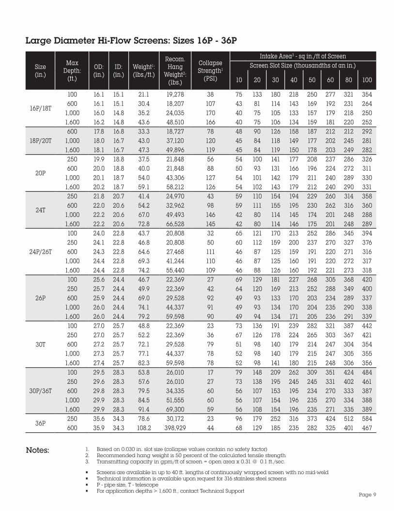
Large Diameter Hi-Flow Screens: Sizes 16P - 36P
1. Based on 0.030 in. slot size (collapse values contain no safety factor)2. Recommended hang weight is 50 percent of the calculated tensile strength3. Transmitting capacity in gpm/ft of screen = open area x 0.31 @ 0.1 ft./sec.
Notes:
• Screens are available in up to 40 ft. lengths of continuously wrapped screen with no mid-weld• Technical information is available upon request for 316 stainless steel screens• P - pipe size, T - telescope• For application depths > 1,600 ft., contact Technical Support
Size(in.)
Max Depth:
(ft.)
OD: (in.)
ID:(in.)
Weight1: (lbs./ft.)
Recom. Hang
Weight2: (lbs.)
Collapse Strength1
(PSI)
Intake Area3 - sq in./ft of ScreenScreen Slot Size (thousandths of an in.)
10 20 30 40 50 60 80 100
16P/18T
100 16.1 15.1 21.1 19,278 38 75 133 180 218 250 277 321 354600 16.1 15.1 30.4 18,207 107 43 81 114 143 169 192 231 264
1,000 16.0 14.8 35.2 24,035 170 40 75 105 133 157 179 218 2501,600 16.2 14.8 43.6 48,510 166 40 75 106 134 159 181 220 252
18P/20T600 17.8 16.8 33.3 18,727 78 48 90 126 158 187 212 212 292
1,000 18.0 16.7 43.0 37,120 120 45 84 118 149 177 202 245 2811,600 18.1 16.7 47.3 49,896 119 45 84 119 150 178 203 249 282
20P
250 19.9 18.8 37.5 21,848 56 54 100 141 177 208 237 286 326600 20.0 18.8 40.0 21,848 88 50 93 131 166 196 224 272 311
1,000 20.1 18.7 54.0 43,306 127 54 101 142 179 211 240 289 3301,600 20.2 18.7 59.1 58,212 126 54 102 143 179 212 240 290 331
24T
250 21.8 20.7 41.4 24,970 43 59 110 154 194 229 260 314 358600 22.0 20.6 54.2 32,962 98 59 111 155 195 230 262 316 360
1,000 22.2 20.6 67.0 49,493 146 42 80 114 145 174 201 248 2881,600 22.2 20.6 72.8 66,528 145 42 80 114 146 175 201 248 289
24P/26T
100 24.0 22.8 43.7 20,808 32 65 121 170 213 252 286 345 394250 24.1 22.8 46.8 20,808 50 60 112 159 200 237 270 327 376600 24.3 22.8 64.6 27,468 111 46 87 125 159 191 220 271 316
1,000 24.4 22.8 69.3 41,244 110 46 87 125 160 191 220 272 3171,600 24.4 22.8 74.2 55,440 109 46 88 126 160 192 221 273 318
26P
100 25.6 24.4 46.7 22,369 27 69 129 181 227 268 305 368 420250 25.7 24.4 49.9 22,369 42 64 120 169 213 252 288 349 400600 25.9 24.4 69.0 29,528 92 49 93 133 170 203 234 289 337
1,000 26.0 24.4 74.1 44,337 91 49 93 134 170 204 235 290 3381,600 26.0 24.4 79.2 59,598 90 49 94 134 171 205 236 291 339
30T
100 27.0 25.7 48.8 22,369 23 73 136 191 239 282 321 387 442250 27.0 25.7 52.2 22,369 36 67 126 178 224 265 303 367 421600 27.2 25.7 72.1 29,528 79 51 98 140 179 214 247 304 354
1,000 27.3 25.7 77.1 44,337 78 52 98 140 179 215 247 305 3551,600 27.4 25.7 82.3 59,598 78 52 98 141 180 215 248 306 356
30P/36T
100 29.5 28.3 53.8 26,010 17 79 148 209 262 309 351 424 484250 29.6 28.3 57.6 26,010 27 73 138 195 245 245 331 402 461600 29.8 28.3 79.5 34,335 60 56 107 153 195 234 270 333 387
1,000 29.9 28.3 84.5 51,555 60 56 107 154 196 235 270 334 3881,600 29.9 28.3 91.4 69,300 59 56 108 154 196 235 271 335 389
36P250 35.6 34.3 78.6 30,172 23 96 179 252 316 373 424 512 584600 35.9 34.3 108.2 398,929 44 68 129 185 235 282 325 401 467
Page 9

HiCap™ High Capacity Low Carbon Steel Screens Large Diameter HiCap Screens: Sizes 6P -18T
Size(in.)
Max Depth
(ft.)
OD(in.)
ID(in.)
Weight1 (lbs./ft.)
Recom. Hang
Weight2: (lbs.)
Collapse Strength1
(PSI)
Intake Area3 - sq in./ft. of Screen
Screen Slot Size (thousandths of an in.)
30 40 50 60 80 100
6 P 2501,000
6.66.9
6.05.9
6.315.5
5,10014,500
2661,855
6330
7739
9047
10054
11867
13279
8 T 2501,000
7.57.7
6.76.7
8.717.9
12,90018,100
1821,340
7134
8843
10252
11460
13475
15088
8 P 2501,000
8.78.9
7.97.9
9.920.3
14,10019,900
117871
8339
10250
11860
13270
15587
174102
10 T 2501,000
9.59.7
8.68.6
11.122.6
16,70023,600
90674
9042
11154
12966
14476
17095
189111
10 P250600
1,000
10.910.910.9
9.89.89.8
25.225.225.2
25,40025,40025,400
476476476
484848
616161
747474
858585
106106106
125125125
12 T250600
1,000
11.411.411.4
10.610.610.6
27.127.127.1
29,00029,00029,000
476476476
484848
616161
747474
858585
106106106
125125125
12 P250600
1,000
12.912.913.0
11.811.811.8
29.531.234.3
29,00029,00029,000
288333502
566860
728676
8710392
101119106
126147132
148171155
14 T250600
1,000
12.612.612.6
11.511.511.5
27.527.529.1
23,60023,60023,600
309309357
555566
717184
8585101
99 99116
123123143
144144167
14 P/ 16 T
250600
1,000
14.114.114.1
13.013.013.0
31.331.333.1
28,10028,10028,100
221221255
626274
797994
9595113
110110130
138138160
162162187
16 P/ 18 T
250600
1,000
16.016.016.0
14.814.814.8
35.535.537.7
31,70031,70031,700
152152175
707084
9090
107
108108128
125125148
156156182
183183212
1. Based on 0.030 in. slot size (collapse values contain no safety factor)2. Recommended hang weight is 50 percent of the calculated tensile strength3. Transmitting screen = open area x 0.31 at 0.1 ft./sec.
Notes:• Screens are available in up to 40 ft. lengths of continuously wrapped screen with no mid-weld• Technical information is available upon request for 316 stainless steel screens• P - pipe size, T - telescope• For application depths > 1,000 ft., contact Technical Support
Page 10

Large Diameter HiCap Screens: Sizes 18P - 36P
Size(in.)
Max Depth:
(ft.)
OD (in.)
ID(in.)
Weight1:(lbs/ft.)
Recom. Hang
Weight2
(lbs)
Collapse Strength1
(PSI)
Intake Area3 - sq. in./ft. of Screen
Screen Slot Size (thousandths of an in.)
30 40 50 60 80 100
18 P/ 20 T
250600
1,000
17.917.918.0
16.716.716.7
39.041.546.1
32,60032,60032,600
108125190
789482
100120106
121144127
140165147
175204183
205237214
20 P250600
1,000
20.020.020.1
18.818.818.8
44.046.751.9
38,10038,10038,100
7890
137
8710592
112134118
135160142
157185164
195228204
229265239
24 T250600
1,000
21.921.922.0
20.720.720.7
48.751.757.4
43,50043,50043,500
5968
104
96115101
123147129
148176155
171202180
214249223
251290262
24 P/ 26 T
100250600
1,000
24.224.224.324.4
22.822.822.822.8
53.857.163.274.6
48,10048,10048,10048,100
445178
124
106127111149
136162143189
163194172224
189223198257
236275247313
277320289361
26 P
100250600
1,000
25.825.825.926.0
24.424.424.424.4
57.561.067.679.7
51,70051,70051,70051,700
364264
102
113136119159
145173152201
174207183239
202238211274
252294263334
296341308384
30 T
100250600
1,000
27.127.127.227.3
25.825.825.825.8
59.863.570.383.1
51,70051,70051,70051,700
31365588
118143125167
152182160211
183217192251
212250222287
265308276350
311358323404
30 P/ 36 T
250600
29.729.9
28.328.3
70.491.6
60,10060,100
2867
156183
199211
238275
274315
338384
393442
36 P100250600
100250600
35.735.835.9
34.334.334.3
69,80069,80069,800
83.992.9
109.3
162439
188164219
239210278
286292378
406364461
472426531
1. Based on 0.030 in. slot size (collapse values contain no safety factor)2. Recommended hang weight is 50 percent of the calculated tensile strength3. Transmitting capacity in gpm/ft. of screen = open area x 0.31 at 0.1 ft./sec.
Notes:• Screens are available in up to 40 ft. lengths of continuously wrapped screen with no mid-weld• Technical information is available upon request for 316 stainless steel screens• P - pipe size, T - telescope• For application depths > 1,000 ft., contact Technical Support
Page 11

Large Diameter HiCap Screens: sizes 6P - 16T
Hicap™ High Capacity Low Carbon Steel Galvanized Screens
Size(in.)
Max Depth
(ft.)
OD (in.)
ID(in.)
Weight1
(lbs/ft.)
Recom. Hang
Weight2 (lbs.)
Collapse Strength1
(PSI)
Intake Area3 - sq in./ft. of Screen
Screen Slot Size (thousandths of an in.)
10 20 30 40 50 60 80 100
6 P250
1,0006.66.6
6.05.9
6.37.9
5,1009,600
266266
2525
4646
6363
7777
9090
100100
118118
132132
8 T600
1,0007.57.7
6.76.7
9.216.6
12,10024,100
182573
2919
5237
7152
8865
10277
11488
134106
150121
8 P250600
1,000
8.68.78.8
7.97.97.9
10.414.918.8
13,30013,30026,500
121399385
332222
594142
825859
1017374
1178788
13199
100
153120121
172137139
10 T250600
1,000
9.39.59.6
8.68.68.6
11.716.621.1
19,00015,70031,300
96307297
352424
644546
886464
1098081
1269596
141108109
166131132
186150151
10 P100600
1,000
10.610.710.8
9.89.89.8
13.018.523.3
16,80016,80033,600
65215209
402727
735151
1017272
1249091
144107108
161122123
189147149
211169170
12 T100600
1,000
11.211.211.4
10.410.410.4
14.114.125.4
19,30019,30038,500
5555178
434329
777754
10610676
13113196
152152114
170170130
200200157
223223180
12 P100600
1,000
12.612.712.8
11.811.811.8
15.221.727.2
19,30019,30038,500
39129126
483232
876061
1208586
147107108
171127128
191144145
225175176
251200202
14 T100600
1,000
12.312.512.7
11.611.611.6
14.020.331.7
15,70015,70031,300
42135348
473225
855947
1178467
14410585
167125102
187142117
220172145
245197168
14 P/
16 T
250600
1,000
14.014.114.2
13.113.113.0
23.130.636.1
18,70018,70037,300
96255250
352727
665252
947475
1189495
140113114
159130131
193160162
221187188
Notes:• Screens are available in up to 40 ft. lengths of continuously wrapped screen with no mid-weld• Technical information is available upon request for 316 stainless steel screens• P - pipe size, T - telescope• For application depths > 1,000 ft., contact Technical Support
1. Based on 0.030 in. slot size (collapse values contain no safety factor)2. Recommended hang weight is 50 percent of the calculated tensile strength3. Transmitting capacity in gpm/ft. of screen = open area x 0.31 at 0.1 ft./sec.
Page 12
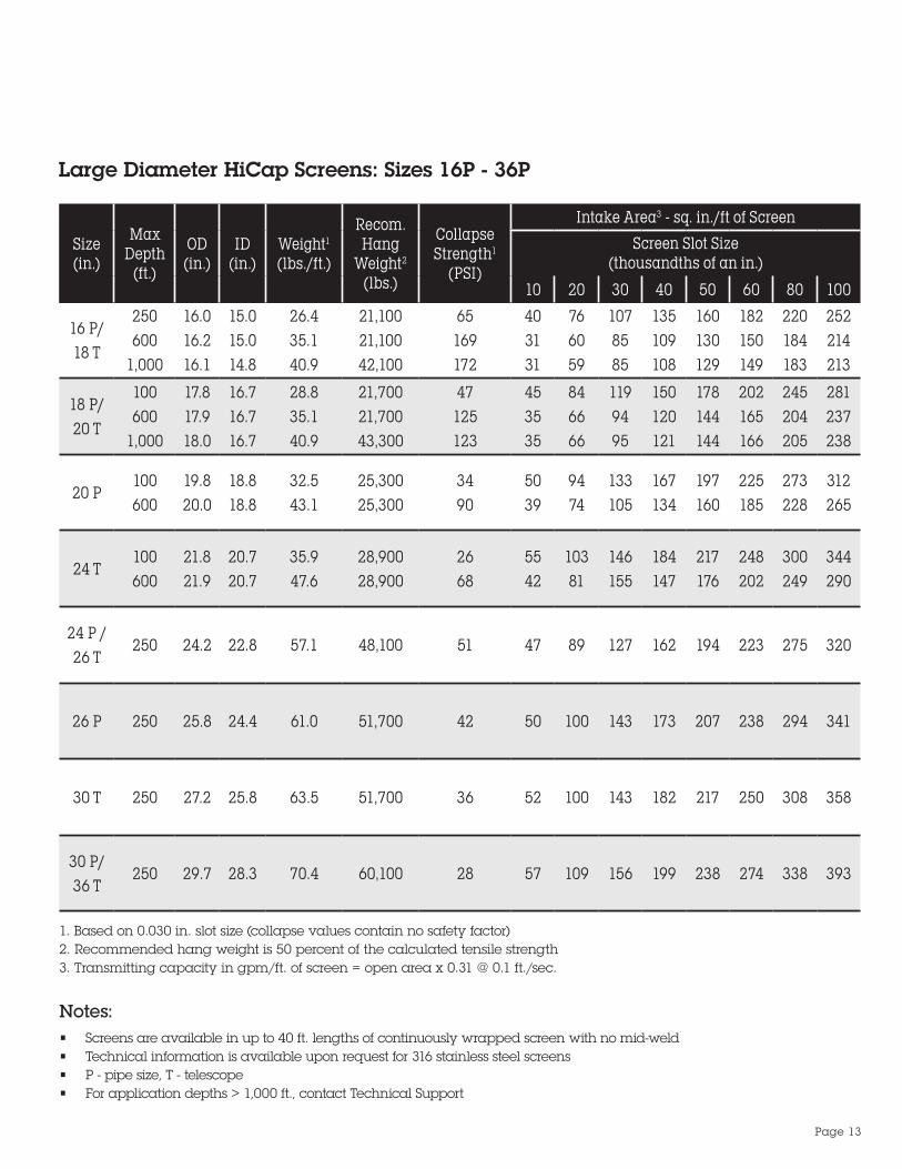
Large Diameter HiCap Screens: Sizes 16P - 36P
Size(in.)
Max Depth
(ft.)
OD(in.)
ID(in.)
Weight1 (lbs./ft.)
Recom. Hang
Weight2
(lbs.)
Collapse Strength1
(PSI)
Intake Area3 - sq. in./ft of Screen
Screen Slot Size (thousandths of an in.)
10 20 30 40 50 60 80 100
16 P/ 18 T
250600
1,000
16.016.216.1
15.015.014.8
26.435.140.9
21,10021,10042,100
65169172
403131
766059
1078585
135109108
160130129
182150149
220184183
252214213
18 P/ 20 T
100600
1,000
17.817.918.0
16.716.716.7
28.835.140.9
21,70021,70043,300
47125123
453535
846666
1199495
150120121
178144144
202165166
245204205
281237238
20 P100600
19.820.0
18.818.8
32.543.1
25,30025,300
3490
5039
9474
133105
167134
197160
225185
273228
312265
24 T100600
21.821.9
20.720.7
35.947.6
28,90028,900
2668
5542
10381
146155
184147
217176
248202
300249
344290
24 P / 26 T
250 24.2 22.8 57.1 48,100 51 47 89 127 162 194 223 275 320
26 P 250 25.8 24.4 61.0 51,700 42 50 100 143 173 207 238 294 341
30 T 250 27.2 25.8 63.5 51,700 36 52 100 143 182 217 250 308 358
30 P/ 36 T
250 29.7 28.3 70.4 60,100 28 57 109 156 199 238 274 338 393
1. Based on 0.030 in. slot size (collapse values contain no safety factor)2. Recommended hang weight is 50 percent of the calculated tensile strength3. Transmitting capacity in gpm/ft. of screen = open area x 0.31 @ 0.1 ft./sec.
Notes:• Screens are available in up to 40 ft. lengths of continuously wrapped screen with no mid-weld• Technical information is available upon request for 316 stainless steel screens• P - pipe size, T - telescope• For application depths > 1,000 ft., contact Technical Support
Page 13
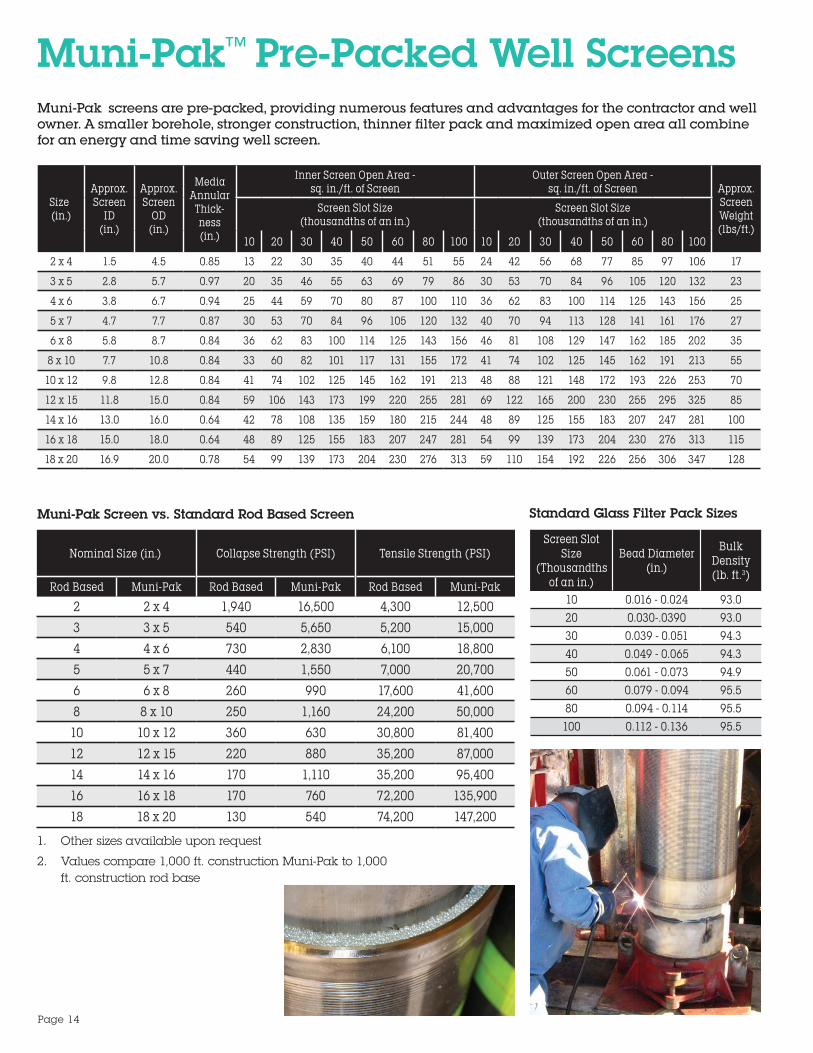
Muni-Pak™ Pre-Packed Well ScreensMuni-Pak screens are pre-packed, providing numerous features and advantages for the contractor and well owner. A smaller borehole, stronger construction, thinner filter pack and maximized open area all combine for an energy and time saving well screen.
Size¹(in.)
Approx. Screen
ID (in.)
Approx. Screen
OD (in.)
Media Annular
Thick-ness(in.)
Inner Screen Open Area - sq. in./ft. of Screen
Outer Screen Open Area - sq. in./ft. of Screen Approx.
Screen Weight(lbs/ft.)
Screen Slot Size (thousandths of an in.)
Screen Slot Size (thousandths of an in.)
10 20 30 40 50 60 80 100 10 20 30 40 50 60 80 100
2 x 4 1.5 4.5 0.85 13 22 30 35 40 44 51 55 24 42 56 68 77 85 97 106 17
3 x 5 2.8 5.7 0.97 20 35 46 55 63 69 79 86 30 53 70 84 96 105 120 132 23
4 x 6 3.8 6.7 0.94 25 44 59 70 80 87 100 110 36 62 83 100 114 125 143 156 25
5 x 7 4.7 7.7 0.87 30 53 70 84 96 105 120 132 40 70 94 113 128 141 161 176 27
6 x 8 5.8 8.7 0.84 36 62 83 100 114 125 143 156 46 81 108 129 147 162 185 202 35
8 x 10 7.7 10.8 0.84 33 60 82 101 117 131 155 172 41 74 102 125 145 162 191 213 55
10 x 12 9.8 12.8 0.84 41 74 102 125 145 162 191 213 48 88 121 148 172 193 226 253 70
12 x 15 11.8 15.0 0.84 59 106 143 173 199 220 255 281 69 122 165 200 230 255 295 325 85
14 x 16 13.0 16.0 0.64 42 78 108 135 159 180 215 244 48 89 125 155 183 207 247 281 100
16 x 18 15.0 18.0 0.64 48 89 125 155 183 207 247 281 54 99 139 173 204 230 276 313 115
18 x 20 16.9 20.0 0.78 54 99 139 173 204 230 276 313 59 110 154 192 226 256 306 347 128
1. Other sizes available upon request
2. Values compare 1,000 ft. construction Muni-Pak to 1,000 ft. construction rod base
Muni-Pak Screen vs. Standard Rod Based Screen
Nominal Size (in.)² Collapse Strength (PSI) Tensile Strength (PSI)
Rod Based Muni-Pak Rod Based Muni-Pak Rod Based Muni-Pak
2 2 x 4 1,940 16,500 4,300 12,500
3 3 x 5 540 5,650 5,200 15,000
4 4 x 6 730 2,830 6,100 18,800
5 5 x 7 440 1,550 7,000 20,700
6 6 x 8 260 990 17,600 41,600
8 8 x 10 250 1,160 24,200 50,000
10 10 x 12 360 630 30,800 81,400
12 12 x 15 220 880 35,200 87,000
14 14 x 16 170 1,110 35,200 95,400
16 16 x 18 170 760 72,200 135,900
18 18 x 20 130 540 74,200 147,200
Standard Glass Filter Pack Sizes
Screen Slot Size
(Thousandths of an in.)
Bead Diameter (in.)
Bulk Density (lb. ft.3)
10 0.016 - 0.024 93.020 0.030-.0390 93.030 0.039 - 0.051 94.340 0.049 - 0.065 94.350 0.061 - 0.073 94.960 0.079 - 0.094 95.580 0.094 - 0.114 95.5
100 0.112 - 0.136 95.5
Page 14

Pipe Based Well ScreensPipe based well screens combine the hydraulic efficiency of wire-wound screens with the strength of pipe. Because of the strength of the pipe liner, the wrap wires can be smaller, producing a greater open area.
The longitudinal support rods on the screen jacket create channels, which direct incoming flow to the nearest pipe perforation. Screen and pipe are welded to make a rugged, reliable unit suitable for deep vertical wells and supply wells.
Stainless Steel Pipe Based Well Screens
Size(in.)
Pipe OD (in.)
Pipe Open Area Per
ft./sq. (in2.)
Screen OD
(in.)
Approx. Weight (lbs.)
Open Area - sq. in./ft. of ScreenScreen Slot Size (thousandths of an in.)
10 15 20 25 30
1.5 1.90 7.95 2.33 4 9.0 13.0 16.0 19.0 22.02.0 2.38 9.28 2.81 5 11.0 15.0 19.0 23.0 27.02.5 2.88 10.60 3.68 7 12.0 18.0 23.0 27.0 31.03.0 3.50 11.93 3.94 10 15.0 21.0 27.0 33.0 37.04.0 4.50 28.27 4.96 14 19.0 27.0 34.0 41.0 47.05.0 5.56 35.34 5.96 17 23.0 32.0 41.0 49.0 57.06.0 6.63 40.06 7.11 24 27.0 38.0 49.0 59.0 68.07.0 7.00 37.70 7.48 35 28.0 41.0 52.0 62.0 71.0
7.625 7.63 42.41 8.12 44 31.0 44.0 56.0 67.0 77.08 8.63 49.48 9.48 38 36.0 52.0 66.0 78.0 90.0
9.625 9.63 49.48 10.24 41 39.0 56.0 71.0 88.0 97.010.0 10.75 56.55 11.30 49 43.0 61.0 78.0 93.0 107.012.0 12.75 65.97 12.41 60 51.0 73.0 93.0 111.0 127.014.0 14.00 70.69 14.70 69 56.0 80.0 102.0 121.0 140.016.0 16.00 75.40 16.73 78 64.0 91.0 116.0 138.0 159.0
Pipe Based Well Screen
Weight is based on standard wall pipe, except for 7.625 in.
Notes:
Page 15

Pipe Size Nom. Diam. (in.)
Sch. OD(in.)
ID(in.)
Weight Perft.
Collapse Strength
(PSI)
1.05
1040
1.3151.1851.0971.049
0.881.421.70
2,445
1.255
1040
1.6601.5301.4421.380
1.121.822.29
1,3623,2714,736
1.55
1040
1.9001,7701,6821,610
1.292.102.74
1,0742,7044,177
2.05
1040
2.3752.2452.1572.067
1.622.663.69
6501,8243.208
3.05
1040
3.5003.3343.2603.068
3.064.377.65
4681,0502,972
4.05
1040
4.5004.3344.2604.026
3.955.67
10.90
253614
2,303
5.05
1040
5.5635.3452.2955.047
6.417.84
14.75
295486
1,854
6.05
1040
6.6256.4076.3576.065
7.669.3819.15
189319
1,570
8.0 1040 8.625 8.329
7.98113.5328.82
2101,243
10.0 1040 10.750 10.420
10.02018.8340.86
1571,030
12.0 100.375* 12.750 12.390
12.00024.3950.03
126762
Pipe Size Nom.
Diam. (in.)
OD(in.)
ID(in.)
Weight Per (ft.)
Collapse Strength
(PSI)1.0 1.315 1.049 1.68 6,127
1.25 1.660 1,380 2.27 4,743
1.5 1.900 1,610 2.72 4,185
2.0 2.375 2.067 3.65 3,219
3.0 3.500 3.068 7.58 2,983
4.0 4.500 4.026 10.79 2,316
5.0 5.563 5.047 14.62 1,869
6.0 6.625 6.065 18.97 1,585
8.0 8.625 7.981 28.55 1,259
10.0 10.750 10.020 40.48 1,045
12.0* 12.750 12.000 49.56 776
* Standard wall
Casings304 Stainless Steel Casings Sch. 40 Low Carbon Steel Casings
* Standard wall
Page 16

Well ScreensGeneral: Well screens shall be of the continuous slot design to provide maximum open area, to reduce entrance velocity, increase hydraulic efficiency and promote more effective development. The well screens shall be constructed of Vee-Wire® trapezoidal wire, continuously wrapped around an array of equally spaced support rods of the same material. Each junction of wire/rod contact shall be resistance welded. The screens and end fittings shall be made of __________ (material). The well screens shall be the Johnson Screens product brand, or an approved equal.
Collapse strength: Well screens shall be __________ inches OD, continuous slot wire-wrapped __________ (material), designed to withstand a minimum collapse pressure of ______ psi for a _____ inch slot opening. The surface wire shape shall cause the slot opening to widen inwardly to minimize clogging. Surface wrap-wire height shall be _____ inches to provide the desired collapse strength. The wrap-wire face width shall be of minimum dimensions to provide _____ percent open area at the anticipated _____ inch slot opening.
Tensile strength: The minimum screen tensile strength must exceed at least twice the total weight of the screen and any standard wall blank casing suspended below the top screen joint. The tensile strength shall be a minimum of _____ pounds. (Tensile strength is total rod area times material yield strength.)
Screen configuration: Screens shall be manufactured in various lengths complete with __________ (material) weld rings attached to each end. The weld rings shall be standard available lengths as requested by the contractor and approved by the engineer.
Screen SubmittalsUpon request, the screen manufacturer shall provide a submittal and schematic drawing of the proposed screen design. The documents shall include the OD, ID, construction materials, slot size, approximate weight per foot, wrap-wire length, wrap-wire height, collapse strength, percent open area, inlet open area per foot, transmitting capacity per foot, number of support rods, diameter of support rods, total cross sectional rod area, material yield strength, tensile strength, column load and recommended hang weight.
Muni-Pak™ screensGeneral: Muni-Pak™ screens shall be of the continuous slot design to provide maximum open area, to reduce entrance velocity, increase hydraulic efficiency and promote more effective development. Both the inner and outer screens shall be constructed out of Vee-Wire traezoidal wire, continuously wrapped around an array of equally spaced support rods of the same material. Each junction of wire/rod contact shall be resistance welded. The screens and end fittings shall be made of __________ (material).The well screens shall be the Johnson Screens product brand, or an approved equal.
Diameter: The Muni-Pak screen shall be _____ inch pipe size inner screen by _____ inch pipe size outer screen.
Collapse: The dual screen assembly shall be manufactured with a wrap-wire designed to yield a minimum collapse pressure of _____ psi at a design slot opening of _____ inches. The wire shape shall cause the slot opening to widen inwardly to minimize clogging.
Open area: The inner screen shall provide _____ square inches of inlet area per foot of screen at the design slot size. The outer screen shall be of the same slot as the inner screen. The slot size and filter pack are to be selected on the basis of a sieve analysis of the water bearing formation.
Filter pack: The annulus between screens shall be filled with ceramic or glass beads of uniform size and excellent sphericity. The pack size shall be _____ filter size. The pack material shall be installed and compacted by vibrating the unit in a vertical position while being filled. The top and bottom filter seal plates shall be secured by welding.
Tensile strength: The minimum screen tensile strength must exceed at least twice the total hang weight of the screen and blank casing below the top screen joint. The tensile strength shall be a minimum of ___ pounds. (Tensile strength is total rod area times material yield strength).
Screen configuration: Screens shall be manufactured in various lengths with a maximum of 40 feet length overall. Screens shall be complete with _____ (material) and fittings attached to each end. Standard weld rings are six inches long on each end. Weld rings of longer lengths, or threaded fittings may be requested. Screen barrels shall be provided in standard _____ (overall or full) lengths which _____ (include or exclude) the weld ring lengths. Lengths and end fitting configuration to be requested by the contractor and approved by the engineer.
Specifications
Page 17

Di-Electric CouplingDi-Electric couplings prevent galvanic corrosion in municipal and industrial water well completions.
When two dissimilar metals are coupled in water-saturated environments, the less corrosion-resistant metal corrodes faster from the galvanic cell created. This corrosion can be prevented by eliminating the contact between the two metal surfaces.
A Di-Electric coupling uses non-conducting insulating ring material to isolate the metal surfaces and prevent electrical contact. This feature increases the life of the pipe and the life of the well.
Di-Electric couplings are available for pipe sizes from 1.5 - 24 in. Special sizes or connection adapters are available on request.
Features and Benefits
• In the center of the coupling, an insulating sleeve prevents dissimilar metals from making contact and causing corrosion of the casing. This feature extends the life of the pipe for long-term savings
• The coupling has a small OD, only 1.5 to 2 in. larger than the pipe. This feature saves costs by minimizing the size of the hole to be drilled
• The nominal ID of the string is maintained through the coupling for full design functionality
Page 18

With a well depth just over 1,630 feet, the CUWCD required a screen with extreme tensile and collapse strength for the installation depth.
Using square rods, in lieu of the typical round rods, the design met the required needs.
When tested, tensile strength of the square rod screen design was over 200,000 lbs., well over the calculated string weight of 164,100 lbs.
24 in. screen installed
Central Utah Water Conservancy District (CUWCD) 24 in. Culinary Well
Central Utah Water Conservancy District (CUWCD) 24 in. culinary well
Sample of screen used for the installation
Page 19

Groundwater & WellsRecognized worldwide by engineers, scientists and well drillers, Groundwater & Wells, Third Edition, is used as the authoritative text on hydrogeology, well hydraulics, design, construction and materials and is available for purchase at www.jswaterwell.com.
Groundwater and Wells, Third Edition, includes comprehensive coverage of the accepted practices in well management, and is a valuable tool for anyone who designs, specifies, drills, samples, manages, or interprets data from monitoring or recovery wells
Chemical Cleaning, Disinfection & Decontamination of Water Wells
Chemical Cleaning, Disinfection & Decontamination of Water Wells book is a concise, complete assessment of the important role certain chemicals play in modern water treatment, water system construction and maintenance programs.
Included in this text are complete descriptions of chemicals frequently used in water supply applications. With a focus on effective and efficient use of chemicals, individually or in combination, to achieve better well rehabilitation, water system cleaning and water quality treatment.
Diagrams, formula mixer ratios and other technical data are included, along with proper handling techniques for each chemical and, where appropriate, clear warnings about possible hazards and the conditions that can cause them.
Chemical Cleaning, Disinfection & Decontamination of Water Wells book is in a convenient format for use on job sites, as well as classrooms and labs.
Page 20
www.aqseptence.com
Aqseptence Group, Inc. Water Well Screens
© 2017 Aqseptence Group, Inc. All rights reserved. Aqseptence Group, Inc. assumes no liability for possible errors in catalogs, brochures and other printed material. The technical data in this brochure is subject to change and for illustrative purposes only and should not be applied as published to your individual case. Aqseptence Group reserves the right to alter its products without notice. Any reproduction, distribution, display or use of this information in whole or in part without written authorization of Aqseptence Group is strictly prohibited. 07 _1014.03B
North and South America Phone +1 651 636 3900 Fax +1 651 638 3177 [email protected]