Embed Size (px)
Citation preview

ST60 RudderAngle IndicatorInstrumentOwner’sHandbook
Document number: 81123-3Date: 1st April 2001
123_3cov.p65 06/04/01, 13:121

© Copyright Raymarine Limited 2001
123_3cov.p65 06/04/01, 13:122

Introduction i
ContentsIntroduction ............................................................................ v
EMC conformance ............................................................ v
Data inputs ....................................................................... vi
SeaTalk ....................................................................... vi
Use with SeaTalk Autopilot .................................. vi
Stand alone operation ................................................. vi
Options ............................................................................ vii
Linear transducer ....................................................... vii
Mounting ................................................................... vii
Parts supplied ..................................................................... viii
Chapter 1: Operation ............................................................. 1
1.1 Getting started ............................................................. 1
Calibration requirement .............................................. 1
Displayed information ................................................. 1
Operation with other instruments ................................ 1
1.2 Normal use .................................................................. 1
Display illumination .................................................... 2
1.3 Remote control ............................................................ 2
Chapter 2: Maintenance and Fault Finding ........................ 3
2.1 Maintenance ................................................................ 3
Servicing and safety .................................................... 3
Instrument ................................................................... 3
Transducer ................................................................... 3
Cabling ........................................................................ 3
2.2 Fault finding ................................................................ 4
Preliminary procedures ............................................... 4
2.3 Fault location .............................................................. 4
123_3int.p65 06/04/01, 13:121
ii ST60 Rudder Angle Indicator Instrument Owner’s Handbook
Chapter 3: Installation ........................................................... 5
3.1 Planning your installation ........................................... 5
Site requirements ......................................................... 5
Transducer ............................................................. 5
Instrument .............................................................. 5
EMC guidelines ........................................................... 6
Suppression ferrites ............................................... 7
Connections to other equipment ...................... 7
3.2 Procedures ................................................................... 8
Unpacking ................................................................... 8
Fitting the instrument .................................................. 8
Surface mounting .................................................. 8
Flush mounting ...................................................... 9
Fitting the low-profile bezel ............................. 9
Flush mounting procedure ............................. 11
Bracket mounting ................................................ 12
Fitting transducers ..................................................... 12
Rotary Rudder Reference Transducer ................. 13
Mounting ........................................................ 13
Connecting to the tiller .................................. 14
Linear Rudder Reference Transducer .................. 15
Mounting ........................................................ 16
Transducer cabling .............................................. 17
General ........................................................... 17
Running the cable .......................................... 17
Connecting the instrument ........................................ 18
Introduction ......................................................... 18
Signal connections ............................................... 18
Power supply connections ................................... 19
SeaTalk systems ............................................. 19
Stand alone instruments ................................. 19
123_3int.p65 06/04/01, 13:122

Introduction iii
Chapter 4: Calibration ......................................................... 21
4.1 Introduction .............................................................. 21
EMC conformance .................................................... 21
4.2 Rudder angle offset adjustment ................................ 21
123_3int.p65 06/04/01, 13:123

iv ST60 Rudder Angle Indicator Instrument Owner’s Handbook
123_3int.p65 06/04/01, 13:124
Introduction v
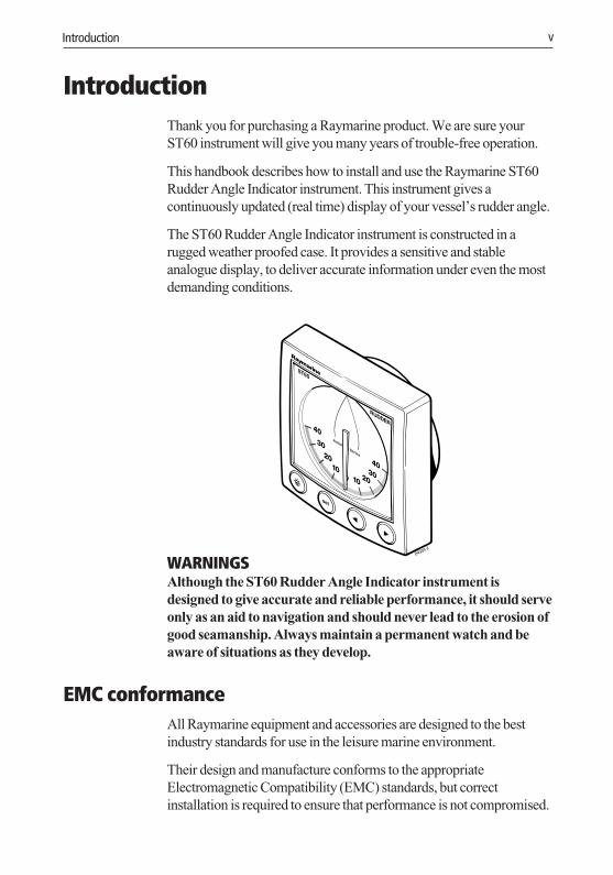
IntroductionThank you for purchasing a Raymarine product. We are sure yourST60 instrument will give you many years of trouble-free operation.
This handbook describes how to install and use the Raymarine ST60Rudder Angle Indicator instrument. This instrument gives acontinuously updated (real time) display of your vessel’s rudder angle.
The ST60 Rudder Angle Indicator instrument is constructed in arugged weather proofed case. It provides a sensitive and stableanalogue display, to deliver accurate information under even the mostdemanding conditions.
D4303-2
WARNINGSAlthough the ST60 Rudder Angle Indicator instrument isdesigned to give accurate and reliable performance, it should serveonly as an aid to navigation and should never lead to the erosion ofgood seamanship. Always maintain a permanent watch and beaware of situations as they develop.
EMC conformanceAll Raymarine equipment and accessories are designed to the bestindustry standards for use in the leisure marine environment.
Their design and manufacture conforms to the appropriateElectromagnetic Compatibility (EMC) standards, but correctinstallation is required to ensure that performance is not compromised.
123_3int.p65 06/04/01, 13:125

vi ST60 Rudder Angle Indicator Instrument Owner’s Handbook
Data inputsThe instrument can be used either as a stand-alone unit, or as part of anintegrated SeaTalk instrumentation system.
SeaTalkWhen connected to SeaTalk, the ST60 Rudder Angle Indicator canoperate as a repeater to any Raymarine SeaTalk autopilot, or providerudder position information to another rudder angle instrument.
SeaTalk enables a number of compatible instruments to beinterconnected and operate as a single, integrated navigational system.
Power and data in a SeaTalk system are fed via a single cable, so thatinstruments be connected by plugging them into the network. SeaTalkis flexible enough to adapt to any number of compatible instrumentswithout requiring a central processor. SeaTalk can also communicatewith non-SeaTalk equipment, using the internationally-acceptedNational Marine Electronics Association (NMEA) protocol.
In a SeaTalk system, each instrument can be either a master ordedicated repeater unit. A master instrument is directly connected to atransducer (the device that provides the raw data) and has control of allother equipment on the SeaTalk network. A slave instrument is notdirectly connected to a transducer but repeats information provided byother equipment in the SeaTalk network.
Use with SeaTalk AutopilotIf the ST60 Rudder Angle Indicator forms part of a system whichincludes a SeaTalk autopilot, the rudder reference transducer isconnected to the autopilot and the Rudder Angle Indicator operates inrepeater mode, i.e. as a slave display to the autopilot, with the autopilotdata displayed using the Rudder Angle Indicator analogue pointer.
Stand alone operationIn Stand alone operation, the ST60 Rudder Angle Indicator isconnected only to a rudder reference transducer and does not displayinformation from, or provide information to, any other instruments.
123_3int.p65 06/04/01, 13:126

Introduction vii
Options
Linear transducerA Linear Rudder Reference Transducer option is available for use with‘bullhorn’ type outboard installations.
MountingIf you do not want to surface mount your ST60 instrument, options areavailable for:
• Flush mounting. If you have ordered the flush mounting option alow-profile bezel and four fixing screws are also provided.
• Bracket mounting.
123_3int.p65 06/04/01, 13:127

viii ST60 Rudder Angle Indicator Instrument Owner’s Handbook
Parts suppliedUnpack your ST60 instrument and check that the following items arepresent:
• Item 1, ST60 Rudder Angle instrument with standard bezel.
• Item 2, Fixing studs (2).
• Item 3, Thumb nuts (2).
• Item 4, Gasket.
• Item 5, Rotary Rudder Reference transducer with fittings (notillustrated).
• Item 6, SeaTalk interconnection cable.
• Item 7, Power cable.
• Item 8, Instrument Cover.
• Item 9, Owner’s Handbook. The Warranty document andmounting templates are included in this Handbook.
• Item 10, Worldwide Service Centre Handbook.
Spare spade terminals are also provided, to re-terminate the transducercable if it has to be cut to facilitate installation.
Note: The above packing list is for an ST60 Rudder Angle Indicatorsystem. Where an instrument is purchased separately, a transducer isnot included.
123_3int.p65 06/04/01, 13:128

Introduction ix
D4443-2
ST60 RudderAngleInstrumentOwner'sHandbook
WorldwideDistributors
1 4
8
32
32
5
6
7
109
123_3int.p65 06/04/01, 13:129

x ST60 Rudder Angle Indicator Instrument Owner’s Handbook
123_3int.p65 06/04/01, 13:1210

Chapter 1: Operation 1
Chapter 1: Operation1.1 Getting started
This handbook describes how to operate, maintain and install theRaymarine ST60 Rudder Angle Indicator Instrument. The instrumentprovides a real-time indication of rudder position as determined by theassociated Rudder Reference Transducer.
Calibration requirementYour ST60 instrument is calibrated to factory (default) settings whenfirst installed and must therefore be calibrated before use, inaccordance with the procedures in Chapter 4, Calibration, to ensureoptimum performance on your vessel.
Do NOT use the instrument until the calibration procedures havebeen satisfactorily completed.
Displayed informationThe information on the Instrument is presented in analogue form(pointer).
The ST60 Rudder Angle Indicator pointer shows the rudder position inreal-time. The instrument scale range gives an expanded indicationfrom -40o to +40o about zero.
Operation with other instrumentsWhen the ST60 Rudder Angle Indicator is connected to an operationalautopilot via SeaTalk, the instrument acts as slave to the autopilotwhich receives data from the Rudder Angle Indicator Transducer andpasses the information via the SeaTalk bus.
1.2 Normal useAs the ST60 Rudder Angle Indicator operates in real time, very littleoperator action is necessary during normal use except to observe theinstrument as required to ascertain the rudder angle.
Note: If rudder angle information is not available on the SeaTalk bus,the analogue pointer oscillates ±10° about the top of the dial.
123_3c01.p65 06/04/01, 13:121

2 ST60 Rudder Angle Indicator Instrument Owner’s Handbook
The key is the only key used during normal operation (see Keyfunctions illustration). The set, < and > keys are reserved forcalibration mode, see Chapter 4, Calibration. All key presses calledfor in this handbook are momentary, unless otherwise stated.
D4425-2Key functions
Used for calibration (see Chapter 4, Calibration )
Press for 1 secondto adjust illumination level
Display illuminationWhen the instrument is first powered up, the display illumination is setto its lowest (courtesy) level, to facilitate initial access to the keys.
To adjust the level of display illumination:
1. Hold down the key for approximately 1 second, to enter theillumination-adjust mode.
2. There are four preset illumination levels from a courtesy level tofull brightness. Momentarily press the key to cycle throughthese levels until you reach the level you want. The selected levelis transmitted to all other instruments on the SeaTalk bus.
3. Press any other key to leave the illumination-adjust mode.
Note: The display will return to normal operation 7 seconds after thelast key press.
1.3 Remote controlUnlike other instruments in the ST60 series, the ST60 Rudder AngleIndicator does not support remote control.
123_3c01.p65 06/04/01, 13:122

Chapter 2: Maintenance and Fault Finding 3
Chapter 2: Maintenance and Fault Finding2.1 Maintenance
Servicing and safety• Raymarine equipment should be serviced only by authorised
Raymarine service engineers. There are no user-serviceable parts inany Raymarine product.
• Some products generate high voltages, and so never handle thecables/connectors when power is being applied to the equipment.
• Always report any EMC related problem to your nearestRaymarine dealer. We will use any such information to improveour quality standards.
When requesting service, please quote equipment Type and ModelNumber.
InstrumentCertain atmospheric conditions may cause condensation to form oninside of the instrument window. This will not harm the instrument andcan be cleared by increasing the instrument illumination to thebrightest setting.
Periodically clean your ST60 instrument with a soft damp cloth. DoNOT use chemical and/or abrasive materials to clean the instrument.
TransducerRefer to the Installation and Maintenance instructions supplied withthe transducer.
CablingExamine all cables for chafing or other damage to the outer shield and,where necessary, replace and re-secure.
123_3c02.p65 06/04/01, 13:123

4 ST60 Rudder Angle Indicator Instrument Owner’s Handbook
2.2 Fault finding
Preliminary proceduresChanges in the electronic environment may adversely affect theoperation of your ST60 equipment. Typical examples of such changesare:
• Electrical equipment has recently been installed or moved aboardyour vessel.
• You are in the vicinity of another vessel or shore station emittingradio signals.
If you appear to have a problem, first ensure that the EMCrequirements (see Chapter 3, Installation) are still being met beforefurther investigating the problem.
2.3 Fault locationAll Raymarine products are subjected to comprehensive test andquality assurance programmes prior to packing and shipping. If a faultoccurs, the following table may help to identify and rectify theproblem.
Fault Cause Remedy
No rudder angle information No power supply Check power supply.
Check SeaTalk cablingand connector security
Check fuse/circuit breaker
No transfer of information SeaTalk cabling fault Check security of SeaTalkbetween instruments connectors.or a group of instruments(e.g. illumination levels). Check condition of
SeaTalk cables.
Isolate faulty instrumentby disconnectinginstruments one by one.
123_3c02.p65 06/04/01, 13:124

Chapter 3: Installation 5
Chapter 3: InstallationThis chapter describes how to install the ST60 Rudder Angle Indicatorinstrument and associated transducer.
You can use either one of two Raymarine Rudder Angle Transducertypes in conjunction with the ST60 Rudder Angle Indicatorinstrument:
If the instrument is being installed as stand-alone, the transducer cableis connected to the rear of the instrument. If being installed as part of asystem incorporating a SeaTalk Autopilot, the transducer is connectedto the Autopilot.
For advice, or further information regarding the installation of thisequipment, please contact the Raymarine Product Support Departmentor your own National Distributor.
3.1 Planning your installationBefore starting the installation, spend some time considering the bestpositions for the instrument, such that the Site requirements and theEMC Guidelines are satisfied.
Site requirements
TransducerThe siting of the Rudder Reference Transducer depends on the type ofvessel. Fitting details and dimensions are given in the Fittingtransducers section of this Chapter.
Instrument
CAUTION:The presence of moisture at the rear of the instrument could causedamage either by entering the instrument through the breathinghole or by coming into contact with the electrical connectors.
ST60 instruments can be fitted either above or below deck, providedthat the rear of the instrument is sited where it is protected from contactwith water.
123_3c03.p65 06/04/01, 13:125

6 ST60 Rudder Angle Indicator Instrument Owner’s Handbook
Each instrument must also be positioned where it is:
• Easily read by the helmsman.
• Protected against physical damage.
• At least 230 mm (9 in) from a compass.
• At least 500 mm (20 in) from radio receiving equipment.
• Reasonably accessible from the rear for installation and servicing.
110mm (4.33in) 24mm(0.95in)
15mm(0.6in)
90m
m (4
.33i
n)di
amet
er
115m
m (4
.53i
n)
123mm (4.85in) 6.2mm(0.25in)
35mm(1.4in)
90m
m (4
.33i
n)di
amet
er
123m
m (4
.85i
n)
D4397-2Instrument dimensions
With standardbezel
With lowprofile bezel
EMC guidelinesAll Raymarine equipment and accessories are designed to the bestindustry standards for use in the leisure marine environment.
Their design and manufacture conforms to the appropriateElectromagnetic Compatibility (EMC) standards, but correctinstallation is required to ensure that EMC performance is notcompromised. Although every effort has been taken to ensure that theywill perform under all conditions, it is important to understand whatfactors could affect the operation of this product.
123_3c03.p65 06/04/01, 13:126

Chapter 3: Installation 7
To minimise the risk of operating problems:
• All Raymarine equipment and cables connected to it should be:
• At least 1 m (3 feet) from any equipment transmitting or cablescarrying radio signals, e.g., VHF radios, cables and antennas. Inthe case of SSB radios, the distance should be increased to2 m (7 ft).
• More than 2 m (6 ft) from the path of a radar beam. A radarbeam can normally be assumed to spread 20° above and belowthe radiating element.
• The equipment should be supplied from a different battery than theone used for engine start. Voltage drops below 10 V in the powersupply to our products can cause the equipment to reset. This willnot damage the equipment, but will cause the loss of someinformation and can change the operating mode.
• Genuine Raymarine cables should be used at all times. Cutting andrejoining these cables can compromise EMC performance and soshould be avoided unless doing so is detailed in the installationmanual.
• If a suppression ferrite is attached to a cable, this ferrite should notbe removed. If the ferrite has to be removed during installation itmust be reassembled in the same position.
Suppression ferritesThe following illustration shows the typical range of suppressionferrites fitted to Raymarine equipment. Always use the ferritesspecified by Raymarine.
Connections to other equipment
If your Raymarine equipment is going to be connected to otherequipment using a cable not supplied by Raymarine, a suppressionferrite MUST always be fitted to the cable close to the Raymarine unit.
123_3c03.p65 06/04/01, 13:127

8 ST60 Rudder Angle Indicator Instrument Owner’s Handbook
3.2 ProceduresAs it is not possible to describe procedures for all possible installationscenarios, the procedures given here describe the broad requirementsfor installing an ST60 Rudder Angle Indicator instrument and itsassociated transducer. Adapt these procedures as appropriate, to suityour individual requirement.
CAUTION:Where it is necessary to cut holes (e.g. for cable routing andinstrument mounting), ensure that these will not cause a hazard byweakening critical parts of the vessel’s structure.
UnpackingUnpack your ST60 instrument and check that the items detailed in theIntroduction to this handbook are present.
Each ST60 instrument is supplied with a standard bezel for surfacemounting. Optional mounting kits are available for flush mounting andbracket mounting the instrument. If you have ordered the flushmounting option, a low-profile bezel and four fixing screws are alsoprovided.
Fitting the instrumentThe ST60 Rudder Angle Indicator instrument can be installed usingone of a number of different mounting options:
• Surface Mounting. Gives a profile of approximately 24 mm.
• Flush Mounting. Gives a profile of approximately 6 mm.
• Bracket Mounting.
The ST60 Rudder Angle Indicator instrument can also be mountedbehind a panel with just the instrument dial and keys visible.
Surface mountingTo surface mount your ST60 instrument (see the Surface mountingillustration):
1. Ensure that:
• The selected location is clean, smooth and flat.
• There is sufficient space behind the location to accommodatethe rear of the instrument and connectors.
123_3c03.p65 06/04/01, 13:128

Chapter 3: Installation 9
2. Apply the surface mount template (supplied at the rear of thishandbook) to the selected location and mark the centres for thefixing studs (1) and the aperture (3) that will take the rear casing ofthe instrument.
3. Drill out the two 5 mm fixing stud clearance holes (2).
4. Cut out the clearance hole (3) then remove the template.
D4331-2Surface mounting4 1 2 1 3 5 2 5
5. Peel off the protective sheet from the self-adhesive gasket (4) thenstick the gasket into position on the rear of the instrument.
6. Screw the two fixing studs into the threaded sockets on the rear ofthe instrument.
7. Mount the assembled instrument, studs, bezel and gasket into thepanel. Secure from behind with the thumb nuts (5).
Flush mountingThe Flush Mounting Kit uses a low-profile bezel to reduce the fittedprofile of the instrument to approximately 6 mm above the panelfascia.
Fitting the low-profile bezelFitting the low-profile bezelFitting the low-profile bezelFitting the low-profile bezelFitting the low-profile bezel
In order to flush-mount your ST60 instrument, replace the standardbezel with the low-profile bezel as follows:
1. Hold the instrument in both hands with the display towards you.
123_3c03.p65 06/04/01, 13:129

10 ST60 Rudder Angle Indicator Instrument Owner’s Handbook
D4537-2
2. Using both thumbs, gently press an upper corner of the instrumentfrom the bezel, then remove the bezel from the instrument. Retainthe rubber keypad which is released when the bezel is removed.
3. Place the instrument face upwards on a flat surface and place therubber keypad (7) in position around the display window (i.e. sothat each key outline is located over its associated key on theinstrument).
4. Snap the low-profile bezel (8) in position over the instrument, sothat the rubber keys are correctly located in the holes on the bezel.
D4358-2Fitting the low profile bezel
78 9
123_3c03.p65 06/04/01, 13:1210

Chapter 3: Installation 11
CAUTION:It is essential that only screws of the correct size are used to securethe instrument to the bezel. Failure to observe this caution couldresult in damage to both the instrument and the bezel.
5. Using the four, self-tapping screws (9) provided, secure theinstrument and bezel together. Fit the screws from the rear of theinstrument and tighten them sufficiently to secure the instrumentand bezel together. DO NOT OVERTIGHTEN.
Flush mounting procedureFlush mounting procedureFlush mounting procedureFlush mounting procedureFlush mounting procedure
Flush mount your instrument (see the Flush mounting illustration) asfollows:
1. Assemble the ST60 instrument and low-profile bezel as describedunder Fitting the low-profile bezel.
2. Ensure that:
• The panel on which you intend to mount the instrument isbetween 3 mm and 20 mm thickness.
• The selected location is clean, smooth and flat.
• There is sufficient space behind the location to accommodatethe rear of the instrument and connectors.
Flush mounting D4332-3
4
1 3 1 5 6 5
123_3c03.p65 06/04/01, 13:1211

12 ST60 Rudder Angle Indicator Instrument Owner’s Handbook
3. Apply the flush mount template (supplied at the rear of thishandbook) to the selected location and mark out the aperture intowhich the assembled instrument and bezel will sit.
4. Cut out the aperture (3) for the assembled instrument and bezeland remove the template.
5. Peel off the protective sheet from the self-adhesive gasket (4) thenstick the gasket into position on the rear of the bezel.
6. Screw the two fixing studs (1) into the threaded sockets on the rearof the instrument.
7. Mount the assembled instrument, studs, bezel and gasket into thepanel.
8. Locate the flush mount bracket (6) onto the fixing studs andsecure the assembly to the panel with the thumb-nuts (5).
Bracket mountingA Control Unit Mounting Bracket (Part No. E25009) enables you tomount your ST60 instrument in locations where other forms ofmounting are impractical. Although bracket mounting provides auseful alternative method for securing your instrument, it is onlysuitable for use in positions where the instrument will not be exposedto water.
To bracket mount your ST60 instrument, do so in accordance with theControl Unit Mounting Bracket Instruction Sheet.
Fitting transducersThe Rudder Reference Transducer duplicates movement of the tillerarm to provide the instrument or the autopilot as appropriate, with theexact position of the vessel’s rudder.
Rotary and Linear Rudder Reference Transducers are available. TheRotary type is suitable for most installations, but the Linear type isdesigned for use with ‘bullhorn’ type outboard installations. Refer tothe fitting instructions for either the Rotary Rudder ReferenceTransducer or the Linear Rudder Reference Transducer, asappropriate.
If you are fitting an ST60 Rudder Angle Indicator instrument as part ofa system which includes a SeaTalk autopilot, the transducer must beconnected directly to the autopilot. The ST60 Rudder Angle Indicatorwill then act as a slave to the autopilot.
123_3c03.p65 06/04/01, 13:1212

Chapter 3: Installation 13
Rotary Rudder Reference Transducer
139.7mm (5.5in)
152mm (6in)
69.5mm (2.7in)
61m
m (2
.4in
)
D4426-1Rotary Rudder Reference Transducer - dimensions
Mounting1. Ensure that the base height of the Rotary Rudder Reference
Transducer is such that it is able to maintain the correct verticalalignment between the transducer and tiller arm (as shown).
D4427-1Vertical alignment of transducer and tiller arm
Tiller arm Transducer
Mounting base
2. Using Rotary Rudder Reference Transducer template (supplied atthe rear of this handbook), mark the centres for the three securingscrews at a suitable location adjacent to the rudder stock.
3. Drill out the three 3 mm holes then, using the three self-tappingscrews provided, secure the Rotary Rudder Transducer inposition.
Note: To ensure precise rudder position indication, the Rotary RudderReference Transducer incorporates a spring to remove anymechanical backlash in the tiller linkage.
123_3c03.p65 06/04/01, 13:1213

14 ST60 Rudder Angle Indicator Instrument Owner’s Handbook
Connecting to the tiller
CAUTION:The Rotary Rudder Reference Transducer arm movement islimited to ±60°. Care must be taken during installation to makesure that the arm is opposite the point of cable entry when therudder is amidships. Failure to do this could result in damage if thearm is driven onto its end stops by the steering system.
When connecting the Rotary Rudder Reference Transducer to thetiller, ensure this is done in accordance with the limits shown in theRotary Rudder Reference Transducer - as fitted illustration (below),and that the tiller and arm of the Rotary Rudder Reference Transducerare parallel to each other.
1. With the rudder amidships, ensure that the Rotary RudderReference Transducer arm is opposite the point of cable entry andat 90° to the connecting bar. If any minor adjustment is necessary,loosen the three securing screws, rotate the Rotary RudderReference Transducer body to achieve the required adjustment,then re-tighten the screws.
A
Parallel
Cableentry
Rudder amidships
± 60 maximumtravelpermitted
D4428-1
Min 101mm (4in)
'A' 140mm (5.5in)
Max 190mm (7.5in)
Min75mm(3in)Max310mm(12.2in)
90 40 max
40 max
Rotary Rudder Reference Transducer - as fitted
123_3c03.p65 06/04/01, 13:1214

Chapter 3: Installation 15
2. Position the tiller pin within the limits shown. Ideally, dimension‘A’ should be 140 mm (5.5 in). Secure the tiller ball-pin to thetiller arm using the two self-tapping screws provided.
Note: Variation within the given limits will not degrade autopilotperformance but will slightly alter the scaling of the ST60 RudderAngle Indicator display.
3. Cut the threaded rod to length and screw one lock-nut and ballsocket onto each end of the rod.
4. Offer up the rod (with ball sockets) to the Rotary RudderReference Arm and tiller, making adjustments to the ball socketsas required then, supporting the ball sockets (by means of asuitable wrench) tighten the locking nuts.
5. Press each socket onto its corresponding ball-pin.
6. Move the rudder from side to side and ensure that the linkage isfree from any obstruction at all rudder angles.
Note: If the Rotary Rudder Reference Transducer has to be mountedin an inverted position, the connections for the red and green wires atthe ST60 Rudder Angle Indicator instrument (or course computer)must be reversed.
Linear Rudder Reference TransducerThe Linear Rudder Reference Transducer is designed for use with‘bullhorn’ type outboard installations.
1110
2
7 8 3 9
56 4
12
1
D4429-1Fitting the Linear Rudder Reference Transducer
123_3c03.p65 06/04/01, 13:1215

16 ST60 Rudder Angle Indicator Instrument Owner’s Handbook
Mounting1. Operate the steering system so that the ‘bullhorn’ ram (1) is
positioned amidships.
2. Release the hydraulic pressure from the vessel’s hydraulicsteering system (if required). Refer to the manufacturer’sinstructions for correct procedures.
3. Loosen the starboard bolt that secures the ‘bullhorn’ ram (1) shaftto the end bracket (2).
4. Assemble the U-bracket (3) over the end bracket (2) and the shaftof the ’bullhorn’ ram (1).
5. Hand tighten the starboard ‘bullhorn’ bolt to hold the U-bracket(3) in position.
6. Fully open the hose clamps (6) using a flat-blade screwdriver.
7. Hang the hose clamps (6) over the ‘bullhorn’ ram (1).
8. Site the spacers (4) on the ‘bullhorn’ ram (1) and hold,temporarily, with adhesive tape.
9. Pull the shaft (9) out of the linear feedback transducer (5) until thealignment mark (10) is level with the end of the body (11).
10. Position the linear feedback transducer (5) on top of the spacers(4) so that the threaded end of the shaft passes through the U-bracket (3).
Note: The linear feedback transducer should, under normalcircumstances, be assembled with the shaft (9) pointing to starboard.However, if it is not possible to orientate the unit in this way, portinstallation is possible provided that the red and green wires arereversed at the ST60 Rudder Angle Indicator instrument (or coursecomputer).
11. With the adjustment screw and barrel aligned with the spacers,close the hose clamps (6) around the linear feedbacktransducer (5) and the ‘bullhorn’ ram (1).
12. Tighten the ‘bullhorn’ bolt to retain the U-bracket (3).
13. Fit and tighten the nut (7) and washer (8) to the shaft of the linearfeedback transducer (5).
123_3c03.p65 06/04/01, 13:1216

Chapter 3: Installation 17
Transducer cabling
GeneralGeneralGeneralGeneralGeneral
Each transducer type is supplied with sufficient cable to run from themounted position to either the ST60 Rudder Angle Indicatorinstrument (for operation as a master) or to an autopilot (for operationas a repeater).
If you are connecting for repeater operation, use the instructions inyour autopilot handbook to connect the transducer to the autopilot.
Running the cable
The manner in which you run the cable will depend on the locations ofthe transducer and instrument (or autopilot). The following guidelinesare provided:
• When running cable from a Linear Rudder Reference Transducer,leave a loop of cable at the end of the Linear Rudder ReferenceTransducer, sufficient to allow for movement of the ‘bullhorn’.
• If the cable has to be fed through the deck, always use a proprietarydeck gland.
• Where cables are fed through holes, always use grommets toprevent chafing.
• Secure long cable runs so they do not present a hazard.
• The transducer cable is fitted with spade connectors for directconnection to the rear of the instrument. However, it may benecessary to remove these to facilitate installation e.g. if you wantincorporate a junction box in the cable run or if the cable has to berouted through narrow apertures. Extra spade connectors areprovided, to replace any that are removed when running the cable.In order to ensure a secure connection when fitting spadeconnectors, fold back the wire strands as shown in the followingillustration, before inserting the wire in the spade connector. Ensurethe wire strands do not extend beyond the rear of the spadeconnector insulation.
D4467-2Preparing wire for connection
3 mm
4 mm
123_3c03.p65 06/04/01, 13:1217

18 ST60 Rudder Angle Indicator Instrument Owner’s Handbook
Connecting the instrument
IntroductionThe ST60 Rudder Angle Indicator instrument can be connected:
• To the transducer as a stand-alone instrument.
• To SeaTalk.
Instruments connected to SeaTalk derive their power directly fromSeaTalk and no separate power connection is necessary. Where aSeaTalk system includes an autopilot, the power for the system isprovided by the autopilot.
A range of Raymarine SeaTalk extension cables is available to connectseparated instruments. These cables are supplied with a SeaTalkconnector fitted to each end. A junction box can be used to join cables.
Signal connectionsMake the necessary connections to your ST60 instrument (see theConnections to ST60 Rudder Angle Indicator instrument illustration).
D4430-1
Cable from transducer
Connections to ST60 Rudder Angle Indicator instrument
SeaTalk cable SeaTalk cable
ScreenGreenBlueRed
Note:If the ST60 Rudder Angle Indicator pointer moves in the wrong direction with respect to the rudder movement, swap the Red and Green connections. This may be necessary if the Rudder Reference Transducer is fitted in a non-standard manner.
123_3c03.p65 06/04/01, 13:1218

Chapter 3: Installation 19
Power supply connections
SeaTalk systems
CAUTIONWhen instruments are connected to SeaTalk, ensure that thepower supply for the SeaTalk 12 V line is protected by a 5 A fuse.
Systems with a large number of instruments on the SeaTalk bus mayrequire connections to the power supply from each end of the system(‘ring-main’ style), to maintain sufficient voltage throughout thesystem.
D4311-1
5 A fused,12 V dc supply
(typically providedby autopilot)
Red
Screen
Red
Screen
1 2 3 4
Instruments5 to 16
17181920
SeaTalk power connections
This requirement depends on the total length of the cable run and thetotal number of instruments in the system, as follows:
Cable run No. of instruments Power connections
Up to 10 m 13 maximum 126 maximum 2
Up to 20 m 7 maximum 113 maximum 2
Stand alone instruments
Stand-alone instruments are not connected to SeaTalk and thereforeneed to be connected to an alternative 12 V power source. Powercables are available in 2 m and 9 m lengths.
123_3c03.p65 06/04/01, 13:1219

20 ST60 Rudder Angle Indicator Instrument Owner’s Handbook
To fit a power cable:
1. Run the cable from the instrument to a suitable 12 V dc powersource.
Power connections for stand-alone instrument
12 V dcsupply
3 A over-currentcircuit breaker
Red
Screen
D4310-6
2. If the cable has not already been trimmed at the power supply end:
a. Cut the cable to length and trim back an appropriate amountof the outer sheath.
b. Cut back and insulate the yellow wire.
3. Connect the screen to the power supply 0 V terminal.
4. Connect the red wire via a 3 A over-current circuit breaker to thepower supply +12 V terminal.
123_3c03.p65 06/04/01, 13:1220

Chapter 4: Calibration 21
Chapter 4: Calibration4.1 Introduction
Before using the Rudder Angle Indicator instrument for navigationalpurposes, it must be aligned with the Rudder Reference Transducer tocounter any offset and ensure that the rudder position is accuratelymonitored.
EMC conformance• Always check the installation before going to sea to make sure that
it is not affected by radio transmissions, engine starting etc.
• In some installations, it may not be possible to prevent theequipment from being affected by external influences. Althoughthis will not damage the equipment, it can lead to spurious resettingaction, or momentarily may result in faulty operation.
4.2 Rudder angle offset adjustmentRudder angle offset adjustment removes any deviation between thereading on the ST60 Rudder Angle Indicator display and the RudderReference Transducer. To adjust for any offset, proceed as follows:
1. Centre the rudder and check that the display analogue pointer iswithin ±7° of zero. If the analogue pointer reading exceeds thelimits ±7°, the Rudder Reference Transducer should be realignedin order to avoid scale inaccuracies, see Chapter 3, Installation.
2. With the rudder centred, press and hold the set key for 2 seconds.The instrument will emit an audible beep to indicate that you arein calibration mode.
Note: You can enter calibration mode only when the instrument is inmaster mode. If the instrument is in repeater mode and you attempt toenter calibration mode, the instrument will beep twice when the setkey is released, to indicate an invalid key press.
3. Use the < (decrement) and/or > (increment) keys to adjust theRudder Angle Indicator display pointer to the zero position in 1°steps, or press and hold either <<<<< or >>>>> for rapid change.
4. Press the set key for 2 seconds to save the new setting and exitcalibration mode.
Note: If, during calibration, no key is pressed for a period of60 seconds, calibration mode is exited without change.
123_3c04.p65 06/04/01, 13:1221

22 ST60 Rudder Angle Indicator Instrument Owner’s Handbook
123_3c04.p65 06/04/01, 13:1222

D4436-1
Machine hole90mm (3.54in)
diameter
Drill 5mm (3/16in) diameter
Drill 5mm (3/16in) diameter
Shaded areas to be removed
TOPST60 Surface Mount Template
123_3tem.p65 06/04/01, 13:1323

123_3tem.p65 06/04/01, 13:1324

Shaded area to be removed
TOP
109 mm
ST60 Flush Mount Template
114
mm
4 holes6 mm diameter
D4437-1
123_3tem.p65 06/04/01, 13:1325

123_3tem.p65 06/04/01, 13:1326

Required position withrudder positioned amidships
Cable position
Drill 3 mm (1/8 in) diameter(shaded area)
D4490-1
Drill 3 mm (1/8 in) diameter(shaded area)
Drill 3 mm (1/8 in) diameter(shaded area)
Rotary Rudder Transducer Mounting Template
123_3tem.p65 06/04/01, 13:1327

123_3tem.p65 06/04/01, 13:1328

Document number: 84064-8April 2001
Limited Warranty CertificateRaymarine warrants each new Light Marine/Dealer Distributor Product to be of good materials and workmanship, and will repair or exchange any parts proven to be defective in material and workmanship under normal use for a period of 2 years/24 months from date of sale to end user, except as provided below.Defects will be corrected by Raymarine or an authorized Raymarine dealer. Raymarine will, except as provided below, accept labor cost for a period of 2 years/24 months from the date of sale to end user. During this period, except for certain products, travel costs (auto mileage and tolls) up to 100 round trip highway miles (160 kilometres) and travel time of 2 hours, will be assumed by Raymarine only on products where proof of installation or commission by authorized service agents, can be shown.
Warranty LimitationsRaymarine Warranty policy does not apply to equipment which has been subjected to accident, abuse or misuse, shipping damage, alterations, corrosion, incorrect and/or non-authorized service, or equipment on which the serial number has been altered, mutilated or removed.Except where Raymarine or its authorized dealer has performed the installation, it assumes no responsibility for damage incurred during installation.This Warranty does not cover routine system checkouts or alignment/calibration, unless required by replacement of part(s) in the area being aligned.A suitable proof of purchase, showing date, place, and serial number must be made available to Raymarine or authorized service agent at the time of request for Warranty service.Consumable items, (such as: Chart paper, lamps, fuses, batteries, styli, stylus/drive belts, radar mixer crystals/diodes, snap-in impeller carriers, impellers, impeller bearings, and impeller shaft) are specifically excluded from this Warranty.Magnetrons, Cathode Ray Tubes (CRT), TFT Liquid Crystal Displays (LCD) and cold cathode fluorescent lamps (CCFL), hailer horns and transducers are warranted for 1 year/12 months from date of sale. These items must be returned to a Raymarine facility.All costs associated with transducer replacement, other than the cost of the transducer itself, are specifically excluded from this Warranty.Overtime premium labor portion of services outside of normal working hours is not covered by this Warranty.Travel cost allowance on certain products with a suggested retail price below $2500.00 is not authorized. When/or if repairs are necessary, these products must be forwarded to a Raymarine facility or an authorized dealer at owner’s expense will be returned via surface carrier at no cost to the owner.Travel costs other than auto mileage, tolls and two (2) hours travel time, are specifically excluded on all products. Travel costs which are excluded from the coverage of this Warranty include but are not limited to: taxi, launch fees, aircraft rental, subsistence, customs, shipping and communication charges etc. Travel costs, mileage and time, in excess to that allowed must have prior approval in writing. TO THE EXTENT CONSISTENT WITH STATE AND FEDERAL LAW:(1) THIS WARRANTY IS STRICTLY LIMITED TO THE TERMS INDICATED HEREIN, AND NO OTHER WARRANTIES OR REMEDIES SHALL BE BINDING ON RAYMARINE INCLUDING WITHOUT LIMITATION ANY WARRANTIES OF MERCHANTABLE OR FITNESS FOR A PARTICULAR PURPOSE.(2) Raymarine shall not be liable for any incidental, consequential or special (including punitive or multiple) damages.All Raymarine products sold or provided hereunder are merely aids to navigation. It is the responsibility of the user to exercise discretion and proper navigational skill independent of any Raymarine equipment.
84064_8.fm Page 1 Monday, April 9, 2001 4:42 PM

Factory Service Centers
United States of America UK, Europe, Middle East, Far EastRaymarine Inc22 Cotton Road, Unit DNashua, NH 03063-4219, USA
Raymarine LtdAnchorage Park, PortsmouthPO3 5TD, England
Telephone: +1 603 881 5200Fax: +1 603 864 4756www.raymarine.com
Telephone: +44 (0)23 9269 3611Fax: +44 (0)23 9269 4642www.raymarine.com
Sales & Order ServicesTelephone: +1 800 539 5539 Ext. 2333 or
+1 603 881 5200 Ext. 2333
Customer SupportTelephone: +44 (0)23 9271 4713Fax: +44 (0)23 9266 1228
Technical SupportTelephone: +1 800 539 5539 Ext. 2444 or
+1 603 881 5200 Ext. 2444Email: [email protected]
Email: [email protected]
Product Repair CenterTelephone: +1 800 539 5539 Ext. 2118
Purchased from Purchase date
Dealer address
Installed by Installation date
Commissioned by
Commissioning date
Owner’s name
Mailing address
This portion should be completed and retained by the owner.
Stick barcode label here
84064_8.fm Page 2 Monday, April 9, 2001 4:42 PM